Abstract
In this paper, plain aluminum was chosen as matrix alloy and graphene reinforced aluminum alloy composites was successfully prepared via powder metallurgy approach. Micro-milling experiments were conducted to explore the effect of varying graphene nanoflakes (GNFs) content (0.5%, 1.0%, and 1.5% by weight) on the machinability of composites and their machining results were compared with that of plain aluminum. Chip morphology, milling force, and machined surface morphology were used as the machinability measures. Experiment results showed that when the content of GNFs is less than 1.5%, the grain refinement of GNFs plays a major role. The hardness and density of the composites are increased. When the content of GNFs is more than 1.5%, the agglomeration phenomenon is obvious, which reduces the hardness and density of the composites. Micro-milling results show that the milling force is the highest when the GNFs content is 1%, and curling degree of chips increased as FPT increase for a certain content of graphene of composites. Furthermore, when the content of GNFs in composites is more than 1%, the surface roughness of milling grooves is greatly improved, which may be related to the lubrication of graphene and the formation of continuous chips.
1. Introduction
Metal matrix composites (MMCs), particularly light metal matrix composites such as aluminum and magnesium have been considered as one of most promising materials in aerospace, electronic packaging, and automotive industries owing to their superior properties such as higher strength-to-weight ratio, lower thermal expansion coefficient and higher resistance to thermal fatigue and creep [1,2,3,4,5,6]. Usually, reinforcement materials for these alloys are silicon carbide, aluminum oxide, boron carbide, and graphite in the form of fibers, whiskers and particles [7,8,9,10]. However, the strength improvement of these alloys is still not enough to be satisfied while the plasticity of the materials is greatly reduced [11,12,13].
In recent years, grapheme-based carbon nano-reinforcements have attracted extensive attention from researchers and become promising solutions to aluminum alloys strengthening. Compared with other reinforcement materials, graphene materials have higher strength, higher modulus, larger specific surface area and better elongation [14,15]. With the availability of bulk qualities of high-quality graphene in recent years, graphene nanoflakes (GNFs) have been applied as promising reinforcing elements in various engineering materials, which can improve the mechanical properties of composites without reducing their electrical and thermal conductivity [16,17]. Previously researches have shown that even very small amount of graphene addition results in increase overall composites properties [18]. However, due to graphene nano-scale size, high surface area and high surface energy difference with metal particles, agglomeration and re-aggregation of the graphene is still a big limitation during the mixing process with metals. Many researchers exercised diverse experimentally strategies to disperse graphene homogeneously within a matrix [19]. Among them, many efforts have been devoted to incorporating graphene platelets in MMCs by powder metallurgy technique [20]. Shin [21] adopted the method of mechanical milling and rolling Gr/Al composite materials was prepared. The mechanical properties of composites were significantly improved due to the addition of graphene. Yan [22] used ball mill and powder metallurgy method to obtain the graphene nano flake reinforced aluminum alloy composites. Graphene is dispersed evenly in aluminum matrix and there is no obvious interfacial reaction between graphene and aluminum matrix, which makes the prepared materials have good mechanical properties.
Besides this, machining of MMCs is notoriously known to be difficult due to both the presence of two or more distinct phases, namely hard reinforcement phase and plastic metal matrix. During the process of machining MMCs, it is easy to cause excessive tool wear, which in turn induces such damage phenomena as fiber pullout, particle fracture, delamination, and debonding at the interface of the fiber or particle with matrix. For this reason, many efforts have been made to produce metal MMCs in near net-shape forms. However, such parts always have to be machined to match the final design requirements such as dimensional accuracy or surface quality of the component [23]. In the past, machining of particulate reinforced MMC has been extensively studied experimentally. From the available literature on machining of MMCs it is obvious that the reinforcement material, characteristics including type, volume fraction and distribution are the factors that affect the overall machinability of these composites [24]. Presently, a few research studies have been conducted on the machining of carbon nanotube composites. Some current research work reported on the carbon nanotube (CNT) polymer composites in micro-scale machining process of the mechanism [25,26,27,28]. The micro milling experiment conducted by Samuel et al. [25,26] and the orthogonal micro turning experiment conducted by Ghai et al. [27] showed that there was a correlation between the CNT content in the composite and its processing response. At a lower CNTs load (1.75 wt%), the plastic deformation of composites plays a leading role in the processing process. Whereas, the CNT content reaches 5 wt%, the interface effect and the distribution of carbon nanotubes determine the processing properties of the composites.
Owing to the unique two-dimensional sheet-type geometry of graphene nanoflakes (GNFs), the mechanics of material deformation and failure in GNFs composites appear to be quite different. Arora [29] studied the effect of graphene platelet loading on the machinability of epoxy-based graphene platelets composites by conducting micro-milling experiments on composites with varying graphene platelets content and their results were contrasted against that of plain epoxy. They concluded that 0.2% GNPs composite has the highest milling force and the lowest tool wear, which was attributed to the improved mechanical properties of the nanocomposite at this nano-filler loading.
Finite element method (FEM) also has been used to understand the fundamental mechanism in machining composite materials. Liu et al. [30] used ABAQUS/Explicit to conduct two-dimensional finite element modeling of SiC/Al and analyzed the removal mechanism and surface quality of granular reinforced aluminum matrix composites after processing by combining with surface roughness test. Gao et al. [31] developed the secondary development program of Abaqus to realize the random and uniform discrete distribution of reinforced particles in the metal matrix. The simulation results show that the cluster phenomenon of particle distribution has certain influence on the cutting behavior.
However, until recently, little research has been found on machinability of graphene reinforced metal matrix. Now, aluminum matrix composites are commonly used in high precision parts, such as engine cylinder liner and avionics components. For this reason, material removal behavior of the composite needs to be well understood and the choice of processing parameters are of great significance for improving machining accuracy and surface quality. In this research, micro-milling process was chosen for investigating the machinability of graphene nano-flakes reinforced aluminum alloy (GNFs/Al) composites since their key process parameters such as edge radius of the tool and chip load are also at the microscale [29]. Here, machinability of GNFs/Al composites was examined in terms of workpiece surface integrity, cutting force, as well as type and shape of the chips. The machinability results of the GNFs/Al composites were compared with that of plain Al.
2. Material Manufacture and Characterization
This section presented the hot pressing sintering process of preparing GNFs/Al composites and the characteristics of the resulted composites.
2.1. Aluminum Microparticles and Graphene Nano-Platelets
Commercial pure aluminum (>99%) powder produced by atomization method and multi-layer graphene powder were used as starting materials here. Scanning electron microscopy (SEM) image of these two powders are shown in Figure 1 by using a Su 8000 FF-SEM (Hitachi, Ltd., Tokyo, Japan).
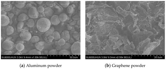
Figure 1.
SEM micrographs of (a) spherical Al powder and (b) graphene nano-flakes (GNFs) powder.
It can be seen from Figure 1 that the aluminum particles are nearly spherical (average size 10–15 μm) and evenly dispersed and graphene is in the form of flakes with certain wrinkle-like shape and a little bit agglomeration occurs. In this research, GNFs/Al composites were prepared by hot pressing sintering. The specific process flow is as follows:
Graphene nano-flakes was first weighed and dispersed into an absolute ethanol (ethanol content ≥99.7%, 200 mL for 0.1 g GNFs, for example) by using ultrasonic sonicator (Jeken ultrasonic cleaning machine PS-20A, Jeken Ultrasonic Cleaner Ltd., Wuhan, China) for 15 min to obtain a homogeneous solution. Then pure aluminum powder was added into the graphene solution with ultrasonic vibration for 30 min to obtain a composite colloid. This mixture was then placed into a DZF-6030A vacuum (Shanghai bluepard instruments Co., Ltd., Shanghai, China) drying oven for 3 h at 80 °C, vacuum of –0.06 MPa to remove residual anhydrous ethanol. After that, ball milling was performed for 2 h on the QM-QX Azimuth planetary ball mill (Nanjing NanDa Instrument Plant, Nanjing, China) ( agate ball to powder ratio: 20:1, rotation speed: 150 r/min and vacuum degree: −0.06 MPa) by adding with 1% paraffin solution and 1% zinc stearate which will be removed during the subsequent sintering process. Finally, composite powder ball-milled (10 g, as shown in Figure 2) was filled into a designed graphite mold for hot pressing sintering process on a RYJ-2000Z medium-frequency sintering machine (Luoyang Yunlin Mechanical Equipment Co., Ltd., Luoyang, China) at a heating rate of 20 °C/min and 600 °C sintering temperature for 10 min. Sample were finally taken out after cooling to a room temperature.
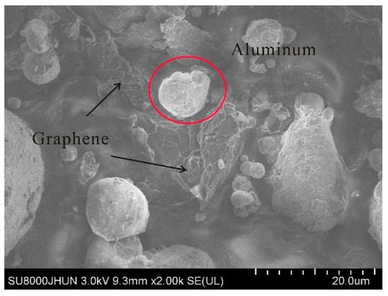
Figure 2.
SEM micrographs of composite particles.
Here, four different weight ratio that is 0.5%, 1%, 1.5%, and 2% of GNFs were used to manufacture GNFs/Al composites, which designated as 0.5% GNFs/Al, 1% GNFs/Al, 1.5% GNFs/Al, and 2% GNFs/Al respectively in the following figures, tables, and chapter.
2.2. Composites Characterization
Microstructure of the GNFs/Al composites and plain aluminum obtained above was observed under optical metallography microscope (Nikon TS2-S-SM, Tokyo, Japan), as shown in Figure 3. Before observation, the samples were grinded by using SiC paper with different meshes and then polished with 0.1 mm diamond gypsum, corroded finally by using 1% hydrofluoric acid (HF) solution. It can be seen that graphene flakes are distributed on the grain boundaries (circled in the figures). By measuring grain size with Image-Pro Plus 6.0. software (Solvusoft Corporation, Las Vegas, NY, USA) the average grain diameter of 0.5% GNFs/Al is 6.78 μm, while that of 1.5% GNFs/Al and 2.0% GNFs/Al is 8.12 µm and 8.37 μm respectively and plain Al is 9.21 μm (as shown in Table 1). This can be explained by the wrinkle structure of graphene which can inhibit the coarsening and growth of aluminum matrix grains and hence resulting the finer grain. In addition, the pinning or wrapping of grains also hinders grain growth during processing and finer grain are obtained. Vickers hardness tests were performed on the composite samples by using HV-1000A microhardness tester (Laizhou Huayin Testing Instrument Co., Ltd., Laizhou, China) under the applied load of 100 g and averaged over the values measurements five times for each sample (as shown in Figure 4). Actual density of composites was measured by using Archimedes method. Theoretic density of composites was calculated as shown in Table 1 according to 2.71 g/cm3 density of aluminum and graphene is negligible for its 0.77 mg/m2 face density and 1–3 nm thickness. Relative density is the ratio of actual density to theoretical density = which is an index to measure the interface bonding state of composite materials. Table 1 gives the hardness values and different density of composited obtained above.
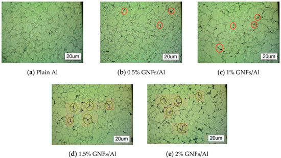
Figure 3.
Metallographic image of plain Al and graphene nanoflakes (GNFs)/Al composites.

Table 1.
Characteristics of composites.
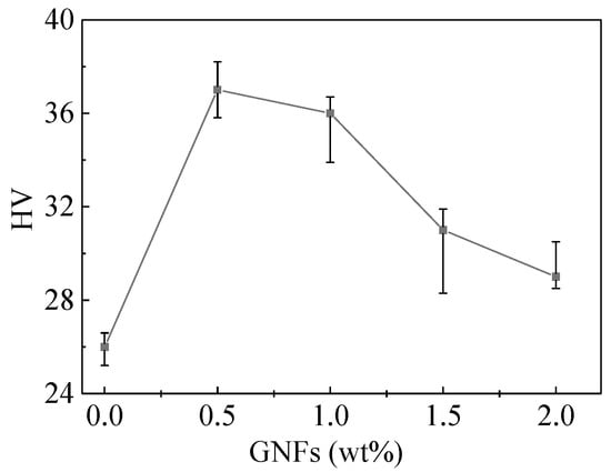
Figure 4.
Microhardness for different GNFs content of composites.
From Table 1, we can see that there is a decrease of GNFs/Al composites density with GNFs content increase. When the content of GNFs is lower than 1.0%, the relative density of the GNFs/Al composites does not change significantly which means good bonding relation between graphene and matrix without too much cavity or porosity. As the content of GNFs increased to 1.5%, the density of the GNFs/Al material decreases obviously, which indicates the agglomeration of graphene has a great influence on the bonding state of reinforcement phase and matrix.
Table 1 also show that as the content of GNFs increased, the microhardness of GNFs/Al composites increases first and then decreases which indicating that the addition of graphene can enhance the hardness of the matrix somewhat. This improvement can be explained by high strength of graphene which can better bear external loads and play a second phase strengthening role and a highly wrinkled structure of graphene which can also hinder the movement of dislocations and hence prevent the deformation of the matrix [32]. However, a common trend observed for all mechanical properties is that there is a limiting content of GNP for enhancing properties, beyond which a remarkable switch-over is observed. The explanation for such behavior lies in the agglomeration of GNPs at high concentration, which then become stress concentrating defects. Such agglomerates promote pore formation and nucleation of micro-cracks which will result in pits on the surface of the sample after corrosion (which can be observed in the metallographic morphology in Figure 3. When GNFs content in GNFs/Al composites reaches a certain threshold, 1.5% here, conglomeration of graphene (as shown in Figure 3) interrupts the consolidation and result in defects in the composite, which bring decrease hardness of GNFs/Al composite. When GNFs content in GNFs/Al composites reaches a certain threshold 1.5% here, conglomeration of graphene (as shown in Figure 3) interrupts the consolidation and result in defects in the composite, which bring decrease hardness of GNFs/Al composites [33].
UMT-TriboLab friction and wear tester (Bruker Nano, Inc. Karlsruhe, Germany) was employed to investigate the tribology behavior of coatings in a dry sliding condition at room temperature. A Si3N4 ball with the diameter of 6 mm were selected as a counterpart. Test parameters are as follows: a normal load of 10 N, sliding velocity of 5 mm/s, reciprocator displacement of 10 mm and test time of 10 min. The worn surface was observed and examined for analyzing. The coefficient of friction (COF) obtained from the experimental results are shown in Figure 5.
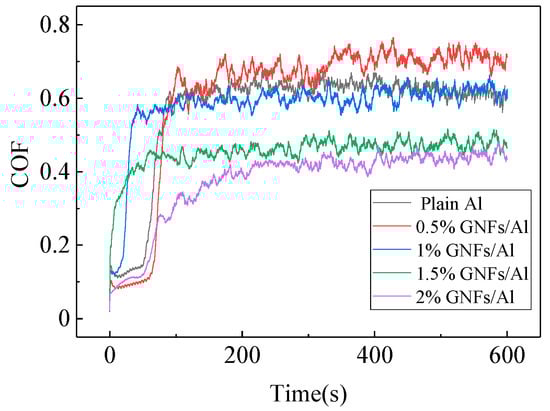
Figure 5.
Friction coefficient for different GNFs/Al composites bulk.
It can be seen from the Figure 5 that the COF of composites decreased with the addition of graphene in general. This is due to the unique two-dimensional planar structure of graphene which makes it easier to enter the contact surface between friction pairs and form a physical adsorption film, which enhances the lubrication effect and reduces friction.
However, the lubrication effect is not obvious when graphene content is comparatively low (0.5%), this can be explained by less lubrication effect with fewer graphene offsets the increasing surface roughness action of the composites (from the following surface roughness analysis), resulting in no significant change in the friction coefficient.
Raman spectra for different GNFs/Al composites were measured by using Bruker Senterra (Bruker, Billerica, MA, USA) as shown in Figure 6. From Figure 6, we can find that there are three main characteristic peaks for graphene. Among of them, D peak is around 1360 cm−1 which indicates lattice defects of carbon atoms, G peak is around 1585 cm−1 indicating the degree of graphitization, and 2D peak is around 2687 cm−1 indicating the appearance and number of layers of graphene. A smaller value of ID/IG represents fewer layers of graphene flakes and better quality of graphene, which can be seen as an index for the interfacial integrity and agglomeration effect.
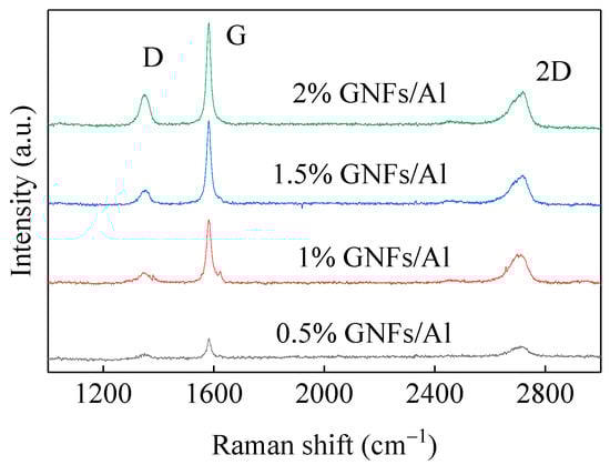
Figure 6.
Micro-Raman spectra for different GNFs/Al composites bulk.
As can be seen from Figure 6, the increase in graphene content brings an increase of the value for both G peak and ID/IG ratio, which suggesting that the increase of graphene graphitization (graphene agglomeration) and grapheme layer numbers [34]. We can also find from Figure 6 that the low D peak value for 0.5% and 1% GNFs/Al which means that the structure of graphene is comparatively complete and comparatively higher D peak values for 1.5% and 2% GNFs/Al which mainly due to the existence of a large number of microcracks, pores and lattice defects caused by agglomerated graphene through sintering process.
3. Micro-Milling Experiment Setup
3.1. Workpieces and Experiment Platform
Slot experiments were performed on the GNFs/Al composites samples with dimensions 15 mm × 18 mm × 10 mm containing 0.5%, 1%, 1.5%, and 2% by weight of GNFs respectively. Before milling operation, all samples are face processed to remove the oxide layer and ensure smoothness and alignment.
Micro-milling slot experiments were carried out on the DMM-22-55 four axes CNC engraving machine with the maximum rotational speed 150,000 r/min. Experimental setup is illustrated in Figure 7.
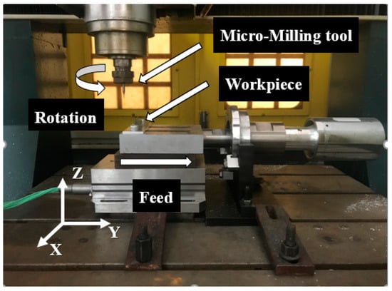
Figure 7.
Layout of experiment setup.
3.2. Process Parameters
Spindle speed 20,000 r/min was adopted. Axial cutting depth was set 200 μm. Different feed rates of 10, 20, 30, 40, and 50 mm/min, respectively, which corresponding to feed per tooth (fz) 0.25, 0.5, 0.75, 1, and 1.25 μm/z, were used respectively. Overall experimental conditions are summarized in Table 2. Length of each slot is fixed at 15 mm and each combination of machining parameters is tested three times to avoid the contingency of experimental data. Similar tests were also performed on the plain Al for comparison. Tests were performed with 1 mm diameter, 2-fluted coated carbide endmill with cutting radius around 2 μm (as shown in Figure 8). Chip morphology, milling force and machined surface morphology were employed as the machinability measures studied. Milling forces Fx, Fy, and Fz were measured using the Kistler quartz 4-components dynamometer 9257B (Kistler Instrumente AG, Winterthur, Switzerland) with multichannel charge amplifier with sampling rate 30 KHz and a DynoWare data acquisition system. A Zeta-20 three dimensional optical profilometer was used to measure the surface roughness along the centerline of the slot. SEM images were used to characterize the morphology of the chips and that of the machined surface.
Table 2.
Experimental conditions.
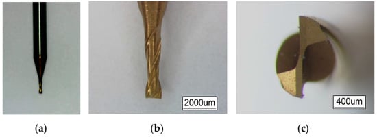
Figure 8.
Micro-milling cutter. (a) Handle; (b) blade; (c) edge
4. Experimental Results and Discussions
4.1. Milling Forces with Different Feed Per Tooth
Usually, milling forces represent an important factor of machinability evaluation: higher milling forces means higher stresses on the tool, causing wear and vibrations and higher stresses on the material causing more damage at higher depth from the machined surface.
It can be seen from Figure 9 that a “rise-fall-rise” trend of milling force is observed with an increase of the feed per tooth (FPT) from 0.5 μm to 1.25 μm both for the plain Al and four different GNFs/Al composites. Here, two transition points are 0.75 μm and 1.0 μm respectively which could be explained as minimum chip thickness (MCT) point and size effect point for micro-milling. Referring to other researches [35], the theoretical minimum chip thickness of plain aluminum is about 0.59 μm and the actual minimum chip thickness is always higher than the theoretical one.
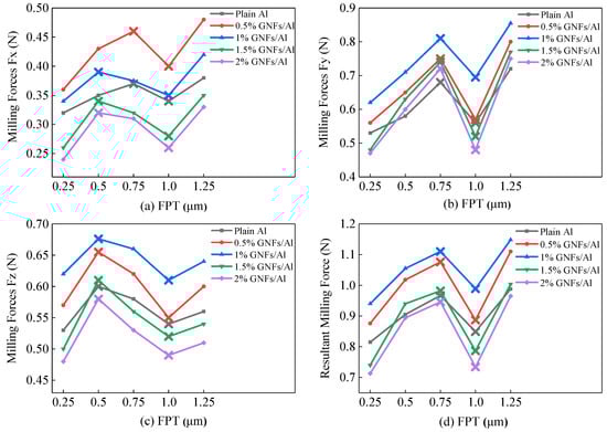
Figure 9.
Milling forces with feed per tooth for different GNFs/Al composites. (a) Radial force (X) direction; (b) feed (Y) direction; (c) axial force (Z) direction; (d) resultant force.
When feed per tooth is 0.75 μm (lower than MCT), no chip is formed and interaction between tool and workpiece is dominated by intense ploughing/rubbing force which increases with the increase of feed per tooth. The milling force reaches its peak value near FPT = 0.75 μm, which is 18.1–32.6% higher than that at FPT = 0.25 μm.
When FPT is between 0.75 and 1 μm, which is higher than the MCT, a shear-based deformation of the material happens and chips begins to form. At this time, part of the friction between tool and workpiece is converted into the shear force between the tool and the chip, which reduces the friction between tool and workpiece decreases resulting in the reduction of Fx, Fy, and Fz. The milling force reaches the valley near FPT = 1 μm, which decreases by 10.9–22.4% compared with that FPT = 0.75 μm.
With the continue increase of FPT value, chip thickness increases, the shear force between tool and chip increases while the decrease of the friction between tool and workpiece. As the FPT increased further to higher than 1 μm, the transition point (size effect) from micro-milling to macro-milling reached, and the shear force plays a dominant role between tool and workpiece. In this case, the milling force rise with FPT which is consistent with that in macro-milling. In the case of FPT = 1.25 μm, the milling force increased by 16.1% to 31.4% compared with that FPT = 1 μm.
4.2. Milling Forces with Different GNFs/Al Composites
From Figure 9, we can get a conclusion that milling forces for 0.5% GNFs/Al and 1.0% GNFs/Al samples are slightly higher while milling force for 1.5% GNFs/Al and 2.0% GNFs/Al are lower compared with that of plain Al samples under same FPT condition.
For 0.5% and 1.0% GNFs/Al composites with comparatively lower graphene content, Fine grain strengthening effect introduced by graphene platelets play a role (as shown in Table 1). During machining process, fine grains will hinder the shear and slip between grains and prevent the generation and propagation of fine cracks. Meanwhile, graphene can also hinder the shear and slip between grains, deflect the crack propagation in grains, and thus reduce the generation and propagation of fine cracks. All these will result comparatively higher milling force in Fx, Fy, and Fz three directions.
For 1.5% and 2.0% GNFs/Al composites in which the content of graphene reaches a certain threshold, agglomeration effect of graphene begins to dominate, which will weaken the mechanical properties of composites and bring grain coarsening, as discussed in Table 1. This weakness and coarse grain will result lower stress required by the composite to undergo plastic deformation during milling process and eventually lead to decrease of milling force.
Furthermore, we can also find from Figure 9 that the corresponding graphene content is different respectively when the milling force reaches its peak value in X, Y, and Z directions. Milling force in the Y and Z directions reaches the maximum as the graphene content is 1%, while the graphene content in the X direction corresponds to the maximum milling force of 0.5%. This is because the milling force in the Y direction mainly comes from the feed resistance to overcome the plastic deformation of the workpiece material. The milling force in Z direction is mainly from the resistance to overcome the elastic deformation of materials. According to Table 1, 1% GNFs/Al composites has the highest mechanical properties. So, the milling force in Y and Z direction reaches the maximum as content of graphene is 1%. For the X direction, the milling force mainly comes from the friction force between the cutter and the workpiece surface, since the core of graphene is C particles which has a certain lubrication effect, the increase of graphene content in the composites can effectively reduce the friction between tool and workpiece.
4.3. Chip Morphology
Figure 10 gives the chip morphologies observed at different FPT respectively for plain Al and different GNFs/Al composites. We can see that for the GNFs/Al composite with certain graphene content, curling degree of the chips increased with FPT increase, which begins as a crack chip at lower FPT and then serrated chip and finally continuous chip with higher FPT.
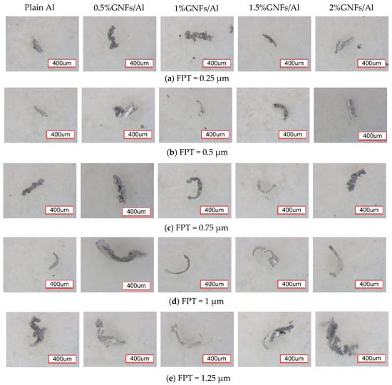
Figure 10.
Chip morphology with different FTP for plain Al and GNFs/Al composites.
When FPT is lower than MCT, interaction between tool and workpiece is dominated by friction action caused by ploughing and shear force is not enough for chip plastic deformation. In this case, chip formed by tool is crushed without plastic deformation, thus resulting crack chips. As FPT continues to increase, shear force between tool and workpiece begins to play a role but still not enough for material to make a complete shear deformation and thus result a serrated chip. Only when FPT is higher than or equal to MCT, shear force becomes play a dominant role between tool and workpiece and thus forming continuous chips. In addition, higher FPT brings higher cutting temperature and hence softening effect of composite materials, which is also the reason for formation of continuous chips.
With continue increase of FPT, shearing force of the tool on the chip increases accordingly which will result the higher bending degree of the chip. On the other hand, as the increase of FPT, temperature between tool and chip bottom will rise which result a temperature difference between top and bottom of chip. The higher the FPT, the bigger temperature difference between the two sides of chip which leads to the corresponding deformation behavior difference on both sides are increasing and a tighter chip curl obtained.
Furthermore, as the grapheme content of composites increase, the chip morphology changes also from crack chip to continuous ones under same FPT condition. This is attributed to two factors: Finer grain effect brought by graphene which will bring the improvement of composites plasticity and lubrication effect which will improve the friction condition between the tool and the workpiece. During the process of micro-milling, the smaller the friction force between the tool and the workpiece, the larger the shear force will be and hence the easier the chip formation.
But when the graphene content reaches a certain value such as 1.5% and 2%, the chip morphology changes abnormally from continuous chip to crack one. It can be explained by that the agglomeration brought by high content of graphene will result defects such as pore, segregation, crack and coarse grains on the interface between aluminum matrix. These defects will make the material removal mechanism of the composites change towards a brittle material one, which eventually leads to a crack chip.
4.4. Surface Integrity
In the following, further considerations will be made concerning the aspects of machinability related to surface integrity.
Figure 11 shows the surface roughness variation of the slot bottom for plain Al and GNFs/Al composites at different FPT. It can be clearly seen from Figure 11 that there is a rise-fall-rise trends for surface roughness as the FPT increase and peak and valley values are near 0.5 μm FPT and 1 μm FPT, respectively. Comparing Figure 11 with Figure 9, it can be found that the change trend of surface roughness of workpiece is consistent with that of milling force. According to the above analysis on milling force, when the value of FPT is less than MCT, the cutting edge is mainly loaded on extrusion and ploughing action. In this case, both chips and cutting heat cannot be taken away in time, which aggravates the generation of surface defects, and finally leads to the increase of machined surface roughness.
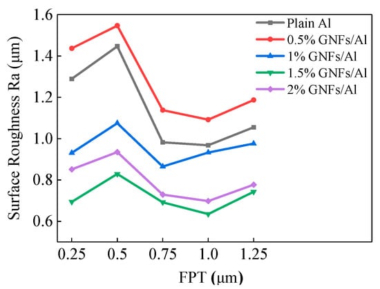
Figure 11.
Surface roughness with different FTP for plain Al and GNFs/Al composites.
When the value of FPT is equal to or higher than MCT, the shear force between tool and workpiece is enough to form continuous chips, which helpful to take away the cutting heat in time. As a result, the plastic deformation of workpiece reduces and the surface quality improves. In addition, the shear force between tool and chip will offset part of the friction action, which will reduce the friction force between tool and machined surface and reduce the roughness of the machined surface also. As the FPT value increase continuously, the shear force then become the dominant force between tool and workpiece. When FPT reach 1 μm, machining process is gradually approaching macro-cutting and milling force on the workpiece in X, Y and Z directions increases with FPT increase, resulting the increase of tremor in the cutting process and roughness of workpiece.
At the same time, the variation trend of surface roughness value in this research is consistent with other research results. Seong et al. [36,37] established the prediction model of the minimum cutting thickness by studying the influence of friction between the tool and the workpiece on the minimum chip thickness and proposed the following formula, in which rn for tool edge radius; β for friction angle; R for tool radius and fr for feed per tooth. It can be obtained from the following formula that when the FPT value is ≥MCT, the value of surface roughness tends to decrease first and then increase as the FPT value increases.
Figure 12 depicts a SEM image of the slot surface for plain Al and GNFs/Al composites under 0.75 μm FTP. Compared with plain Al, the slot surface quality of 0.5% GNFs/Al composite decreased significantly, while the slot surface quality of 1%, 1.5%, and 2% GNFs/Al composites improved obviously. From Figure 12c–e, we can see that there are far few pore, surface scratch and burr formation at the edge of slot. These also attribute to the graphene lubrication effect and grain refinement effect. Wrinkled surface of graphene can inhibit the coarsening and growth of grain and as a result reduce the generation and propagation of micro-cracks and pore during processing [38].
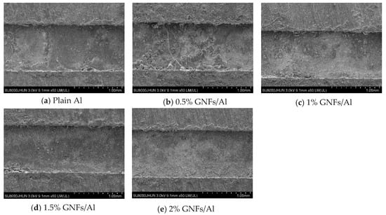
Figure 12.
Slot SEM image for composites with different graphene content under 0.75 μm FTP.
For 0.5% GNFs/Al composites, the milling force is close to the peak value due to higher hardness (shown as Figure 9), which brings comparatively intense vibration between the tool and the workpiece resulting more defects on the machined surface such as cracks, matrix tearing, and surface bulge. With the increase of graphene content of composites, the lubrication effect of graphene becomes dominant and bring with the smoother surface of the machined samples [39,40,41].
Figure 13 gives the slot side image of 1% GNFs/Al composites for down milling side and up milling side to investigate different milling mode effect on the surface quality. It is obvious from Figure 13 that the surface quality on down mill side is obviously better than that of up mill side which is different with the result of convention alloy under up milling and down milling condition.
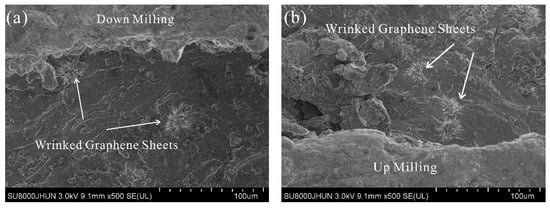
Figure 13.
Both slot side image of 1% GNFs/Al composites at FPT = 0.75 μm. (a) Down milling side; (b) up milling side.
During up milling process, the feed direction of tool is opposite to the movement direction of worktable and chip thickness gradually increases from zero to maximum. In this case, at just beginning, the cutting thickness is very small near to zero, the cutting tool extrudes the workpiece due to the existence of edge radius. Under extrusion action, the graphene reinforced particles are crushed and pushed into the surface of aluminum matrix, resulting the worse surface quality. While, during down milling process, the feed direction of the tool is as same as that of worktable and chip thickness decrease gradually from maximum to zero. At same time, the total contact distance between the tool and the workpiece is relatively shorter than that of up mill. As a result, the extrusion friction effect of the tool on the machined surface is much lower than that of the up milling and the resulted surface quality is slightly better.
5. Conclusions
In this research, micro-milling was carried out on the GNFs/Al composites. The effect of graphene content on the machinability of composites were investigated. Following conclusions can be drawn based on the above findings:
- (1)
- The addition of graphene of GNFs/Al composites has grain refinement, lubrication and agglomeration effect. When the content of graphene is less than 1.0%, the grain refinement of graphene is dominant, which improves the density and hardness of the material. When the content of graphene is higher than 1.5%, the agglomeration effect of graphene occurs, which reduces the density and hardness of the material. At the same time, when the graphene content is 1%, the milling force reaches a peak value because of the dominant role of grain refinement.
- (2)
- It was observed from microscopic image that curling degree of chips increased as FPT increase, which begins as a crack chip at lower FPT and then serrated chip and finally continuous chip with higher FPT. This is due to that chip formation is mainly affected by friction and shear force between tool and workpiece during micro-milling process. At same time, as the graphene content of composites increase, the chip formation changes also from crack morphology to continuous ones under same FPT condition.
- (3)
- The surface roughness results showed that influence of FTP on surface roughness is similar to that of milling force. At same time, when the content of graphene in composites is higher than 1%, the surface roughness of milling grooves is greatly improved, which may be related to the lubrication of graphene and the continuity of chips.
Author Contributions
Conceptualization, L.-H.X., G.-C.H. and L.-H.L.; writing—original draft preparation and methodology, H.-B.N.; investigation and data curation, S.-K.L.; and L.-H.X.; writing—review and editing, L.-H.X., G.-C.H. and H.-B.N.
Funding
This work was supported partly by the National Natural Science Foundation of China (grant no. 21576240).
Conflicts of Interest
The authors declare no conflict of interest.
References
- Bastwros, M.; Kim, G.Y.; Zhu, C.; Zhang, K.; Wang, S.; Tang, X.; Wang, X. Effect of ball milling on graphene reinforced Al6061 composite fabricated by semi-solid sintering. Compos. Part B 2014, 60, 111–118. [Google Scholar] [CrossRef]
- Agarwal, A.; Rao, B.S.; Lahiri, D. Carbon Nanotubes: Reinforced Metal Matrix Composites; CRC Press: Boca Raton, FL, USA, 2010. [Google Scholar]
- Kuruc, M.; Šimna, V.; Necpal, M.; Vopát, T.; Peterka, J. Influence of ultrasound on delamination during machining of GFRP composite material. Solid State Phenom. 2017, 261, 173–178. [Google Scholar] [CrossRef]
- Podymova, N.B.; Karabutov, A.A. Combined effects of reinforcement fraction and porosity on ultrasonic velocity in SiC particulate aluminum alloy matrix composites. Compos. Part B 2017, 113, 138–143. [Google Scholar] [CrossRef]
- Selvakumar, S.; Dinaharan, I.; Palanivel, R.; GaneshBabu, B. Development of stainless steel particulate reinforced AA6082 aluminum matrix composites with enhanced ductility using friction stir processing. Mater. Sci. Eng. A 2017, 685, 317–326. [Google Scholar] [CrossRef]
- Tian, K.; Zhao, Y.; Lei, J.; Zhang, S.; Zhang, Z.; Wu, X. Effects of in situ generated ZrB2 nano-particles on microstructure and tensile properties of 2024Al matrix composites. J. Alloys Compd. 2014, 594, 1–6. [Google Scholar] [CrossRef]
- Min, S.; He, Y.; Fang, S. Yield stress of SiC reinforced aluminum alloy composites. J. Mater. Sci. 2010, 45, 4097–4110. [Google Scholar]
- Pierard, N.; Fonseca, A.; Colomer, J.F.; Bossuot, C.; Benoit, J.-M.; Tendeloo, G.V.; Pirard, J.-P.; Nagy, J.B. Ball milling effect on the structure of single-wall carbon nanotubes. Carbon 2004, 42, 1691–1697. [Google Scholar] [CrossRef]
- Chao, S.; Min, S.; Wang, Z.; He, Y. Effect of particle size on the microstructures and mechanical properties of SiC-reinforced pure aluminum composites. J. Mater. Eng. Perform. 2011, 20, 1606–1612. [Google Scholar]
- Topcu, I.; Gulsoy, H.O.; Kadioglu, N.; Gulluoglu, A.N. Processing and mechanical properties of B4C reinforced Al matrix composites. J. Alloys Compd. 2009, 482, 516–521. [Google Scholar] [CrossRef]
- Soon-Jik, H.; Hong-Moule, K.; Huh, D.; Suryanarayana, C.; SunChun, B. Effect of clustering on the mechanical properties of SiC particulate-reinforced aluminum alloy 2024 metal matrix composites. Mater. Sci. Eng. A 2003, 347, 198–204. [Google Scholar]
- Chawla, N.; Shen, Y.L. Mechanical behavior of particle reinforced metal matrix composites. Adv. Eng. Mater. 2001, 3, 357–370. [Google Scholar] [CrossRef]
- Moghadam, A.D.; Omrani, E.; Menezes, P.L.; Rohatgi, P.K. Mechanical and tribological properties of self-lubricating metal matrix nanocomposites reinforced by carbon nanotubes (CNTs) andgraphene—A review. Compos. Part B 2015, 77, 402–420. [Google Scholar] [CrossRef]
- Stankovich, S.; Dikin, D.A.; Dommett, G.H.B.; Kohlhaas, K.M.; Zimney, E.J.; Stach, E.A.; Piner, R.D.; Nguyen, S.T.; Ruoff, R.S. Graphene-based composite materials. Nature 2006, 442, 282–286. [Google Scholar] [CrossRef] [PubMed]
- Tjong, S.C. Recent progress in the development and properties of novel metal matrix nanocomposites reinforced with carbon nanotubes and graphene nanosheets. Mater. Sci. Eng. R Rep. 2013, 74, 281–350. [Google Scholar] [CrossRef]
- Rashad, M.; Pan, F.; Tang, A.; Lu, Y.; Asif, M.; Hussain, S.; She, J.; Gou, J.; Mao, J. Effect of graphene nanoplatelets (GNPs) addition on strength and ductility of magnesium-titanium alloys. J. Magne. Alloys 2013, 1, 242–248. [Google Scholar] [CrossRef]
- Wang, T.; Zou, C.; Chen, Z.; Li, M.; Wang, W.; Li, R.; Kang, H. In situ synthesis of TiB2 particulate reinforced copper matrix composite with a rotating magnetic field. Mater. Des. 2015, 65, 280–288. [Google Scholar] [CrossRef]
- Han, B.; Yang, Z.; Shi, X.; Yu, X. Transport properties of carbon-nanotube/cement composites. J. Mater. Eng. Perform. 2013, 22, 184–189. [Google Scholar] [CrossRef]
- El-Ghazaly, A.; Anis, G.; Salem, H.G. Effect of graphene addition on the mechanical and tribological behavior of nanostructured AA2124 self-lubricating metal matrix composite. Compos. Part A 2017, 95, 325–336. [Google Scholar] [CrossRef]
- Li, J.L.; Xiong, Y.C.; Wang, X.D.; Yan, S.J.; Yang, C.; He, W.W.; Chen, J.Z.; Wang, S.Q.; Zhang, X.Y.; Dai, S.L. Microstructure and tensile properties of bulk nanostructured aluminum/graphene composites prepared via cryomilling. Mater. Sci. Eng. A 2015, 626, 400–405. [Google Scholar] [CrossRef]
- Shin, S.E.; Choi, H.J.; Shin, J.H.; Bae, D.H. Strengthening behavior of few-layered graphene/aluminum composites. Carbon 2015, 82, 143–151. [Google Scholar] [CrossRef]
- Yan, S.J.; Dai, S.L.; Zhang, X.Y.; Yang, C.; Hong, Q.H.; Chen, J.Z. Investigating aluminum alloy reinforced by graphene nanoflakes. Mater. Sci. Eng. A 2014, 612, 440–444. [Google Scholar] [CrossRef]
- Di Ilio, A.; Paoletti, A. Machinability aspects of metal matrix composites. In Machining of Metal Matrix Composites; Springer: London, UK, 2012; pp. 63–77. [Google Scholar]
- Manna, A.; Bhattacharayya, B. A study on machinability of Al/SiC-MMC. J. Mater. Process. Technol. 2003, 140, 711–716. [Google Scholar] [CrossRef]
- Samuel, J.; DeVor, R.E.; Kapoor, S.G.; Hsia, K.J. Experimental investigation of the machinability of polycarbonate reinforced with multiwalled carbon nanotubes. J. Manuf. Sci. Eng. 2015, 128, 465–473. [Google Scholar] [CrossRef]
- Samuel, J.; Dikshit, A.; DeVor, R.E.; Kapoor, S.G.; Hsia, K.J. Effect of carbon nanotube (CNT) loading on the thermo-mechanical properties and the machinability of CNT-reinforced polymer composites. J. Manuf. Sci. Eng. 2008, 131, 203–213. [Google Scholar]
- Ghai, I.; Samuel, J.; Devor, R.E.; Kapoor, S.G. Effect of carbon nanotube loading on the machinability of polycarbonate nanocomposites. J. Mech. Eng. Mater. Sci. 2007, 1, 75–84. [Google Scholar]
- Dikshit, A.; Samuel, J.; DeVor, R.E.; Kapoor, S.G. Microstructure-level machining simulation of carbon nanotube reinforced polymer composites—Part II: Model interpretation and application. J. Manuf. Sci. Eng. 2008, 130, 031115. [Google Scholar] [CrossRef]
- Arora, I.; Samuel, J.; Koratkar, N. Experimental investigation of the machinability of epoxy reinforced with graphene platelets. J. Manuf. Sci. Eng. 2013, 135, 041007. [Google Scholar] [CrossRef]
- Liu, J.; Cheng, K.; Ding, H.; Chen, S.; Zhao, L. An investigation of surface defect formation in micro milling the 45% sicp/al composite. Procedia CIRP 2016, 45, 211–214. [Google Scholar] [CrossRef]
- Gao, C.; Zhao, X. Factor analysis of machining parameters of SiC nanoparticle-reinforced magnesium matrix composites with consideration of cluster effect. Int. J. Mach. Mach. Mater. 2015, 17, 165. [Google Scholar] [CrossRef]
- Wang, J.; Li, Z.; Fan, G.; Pan, H.; Chen, Z.; Zhang, D. Reinforcement with graphene nanosheets in aluminum matrix composites. Scr. Mater. 2012, 66, 594–597. [Google Scholar] [CrossRef]
- Baig, Z.; Mamat, O.; Mustapha, M. Recent progress on the dispersion and the strengthening effect of carbon nanotubes and graphene-reinforced metal nanocomposites: A Review. Crit. Rev. Solid State Mater. Sci. 2016, 43, 1–46. [Google Scholar] [CrossRef]
- Nieto, A.; Bisht, A.; Lahiri, D.; Zhang, C.; Agarwal, A. Graphene reinforced metal and ceramic matrix composites: A review. Metall. Rev. 2016, 62, 241–302. [Google Scholar] [CrossRef]
- Malekian, M.; Mostofa, M.G.; Park, S.S.; Jun, M.B.G. Modeling of minimum uncut chip thickness in micro machining of aluminum. J. Mater. Process. Technol. 2011, 212, 553–559. [Google Scholar] [CrossRef]
- Son, S.M.; Hanm, S.L.; Ahn, J.H. Effects of the friction coefficient on the minimum cutting thickness in micro cutting. Int. J. Mach. Tools Manuf. 2005, 45, 529–535. [Google Scholar] [CrossRef]
- Barabasi, A.L.; Stanley, H.E. Fractal Concepts in Surface Growth; Press Syndicate of the University of Cambridge: Cambridge, UK, 1995. [Google Scholar]
- Kumar, M.N.; Mahmoodi, M.; Tabkhpaz, M.; Park, S.S.; Jin, X. Characterization and micro end milling of graphene nano platelet and carbon nanotube filled nanocomposites. J. Mater. Process. Technol. 2017, 249, 96–107. [Google Scholar] [CrossRef]
- Rafiee, M.A.; Rafiee, J.; Srivastava, I.; Wang, Z.; Song, H.; Yu, Z.-Z.; Koratkar, N. Fracture and fatigue in graphene nanocomposites. Small 2010, 6, 179–183. [Google Scholar] [CrossRef]
- Rafiee, M.A.; Rafiee, J.; Yu, Z.-Z.; Koratkar, N. Buckling resistant graphene nanocomposites. Appl. Phys. Lett. 2009, 95, 223103. [Google Scholar] [CrossRef]
- Rafiee, M.A.; Rafiee, J.; Wang, Z.; Song, H.; Yu, Z.-Z.; Koratkar, N. Enhanced mechanical properties of nanocomposites at low graphene content. ACS Nano 2009, 3, 3884–3890. [Google Scholar] [CrossRef]


© 2019 by the authors. Licensee MDPI, Basel, Switzerland. This article is an open access article distributed under the terms and conditions of the Creative Commons Attribution (CC BY) license (http://creativecommons.org/licenses/by/4.0/).