Article

Fiber Laser Surface Melting of a NiTi Superelastic Alloy: Influence on Structural and Mechanical Properties

by
David Dias
1,*,
Osmar Sousa Santos
2,
Wellington Alves
1,
Milton Sergio Fernandes Lima
1 and
Maria Margareth da Silva
1
1
Postgraduate Program in Aeronautical and Mechanical Engineering, Instituto Tecnólogico de Aeronáutica, Vila das Acácias, Sao José dos Campos 12200-000, SP, Brazil
2
Engineering Department Universidade Federal de Lavras, Lavras 37200-000, Brazil
*
Author to whom correspondence should be addressed.
Metals 2019, 9(12), 1268; https://doi.org/10.3390/met9121268
Submission received: 30 October 2019 / Revised: 10 November 2019 / Accepted: 19 November 2019 / Published: 27 November 2019
(This article belongs to the Special Issue Surface Engineering of Metals and Alloys)

Abstract

:
The surface melting of a NiTi superelastic alloy using a high-power laser Yb:Fiber was investigated. The influence of this process on the microstructural and mechanical properties was also examined. The reference material was a 3 mm nitinol strip with a homogeneous austenitic B2 phase. For the laser surface melting process, input fluences were applied from 17.5 to 45 J/mm2. The morphology of the structure and the chemical composition of several regions were determined by optical microscopy, scanning electron microscopy, dispersive energy spectra, and X-ray diffraction techniques. The mechanical properties, such as modulus of elasticity and hardness, were determined using nanoindentation and microindentation techniques. The greatest surface finishing of the fusion zone was observed for the condition 35 J/mm2. Three well-defined regions (fusion zone (FZ), heat-affected zone (HAZ), base metal (BM)) could be observed and dimensions of grain size, width, and depth of the melted pool were directly affected by the laser fluence. The geometry of the molten pool could be controlled by the optimization of the laser parameters. High laser fluence caused preferential volatilization of nickel, dynamic precipitation of intermetallic phases, including Ti2Ni, Ni3Ti, and Ni4Ti3, as well as solubilization of TiC in the matrix, which led to grain refinement. Thus, high laser fluence is a suitable technique to enhance mechanical properties such as hardness and Young’s modulus.

1. Introduction

Characteristics of NiTi alloy include shape memory, superelasticity, low modulus of elasticity, high corrosion resistance, and biocompatibility [1]. With high shape recovery, up to 10% at 25 °C, which is much larger than the elastic deformation supported by a conventional metallic material (0.2%) [2], shape memory alloys (SMAs) are in demand for many technical and engineering applications, including consumer products and industrial applications [3], structures and composites [4], automotive [5,6], aerospace [7,8,9,10], mini-actuators and microelectromechanical systems (MEMS) [11,12,13], robotics [14,15], biomedicine [1,16,17,18,19,20], and even fashion [21]. In biomedicine, which is a big field for the NiTi alloys, shape memory alloys have been applied for orthodontic wires [16], self-expanding stents for cardiovascular applications [22], treatment of patella fracture by claw-like shape memory alloy [23], and more, due to their unique properties.
According to material requirements for the potential application, the surface of the NiTi alloy can be laser-treated, which can provide improvements, including corrosion resistance, cavitation erosion resistance (Re), mechanical properties, electrochemical properties, grain refinement, and correction of defects such as pores and cracks. For a specific modification, parameters such as applied power and interaction time on the surface of the material are essential to produce the desired modifications. The generic term “laser surface treatment” includes treatments with and without the addition of materials [24,25]. The treatments without the addition of materials are laser transformation hardening [26], laser texturing [27], laser surface melting [28,29], and laser glazing [30]. The list of treatments with addition of materials include laser cladding [31,32], laser surface alloying [33], and laser welding processes both similar [34] and dissimilar [35,36].
Examination of the cross-sectional geometry of the melting developed under lower laser fluences [37] found that the depth of the melting gradually increased with increased laser fluence. At a fluence of 6.7 J/mm2, suitable mixture of the molten pool together with the top of the titanium surface was evident, which can be completed with a uniform modulus of elasticity of about 80 to 104 GPa. A high-power laser was used by ZD Cui et. al. [28] to melt the surface of NiTi shape memory alloy. The rapid rate of solidification of the fused pool resulted in the formation of a surface layer that consisted of refined and homogenized microstructure. The results indicated that the corrosion resistance of NiTi treated by laser was significantly increased, which was demonstrated by increased passive film-breaking potential and decreased corrosion current. The outer surface of all samples studied was composed of TiO2, NiTi, and other TiO compounds with increased corrosive resistance and reduced release of nickel ions.
Considered a challenging technique, laser surface modification of NiTi alloy has many obstacles still to overcome to achieve the optimization of the laser parameters and desired properties for application. The behaviors of NiTi SMA under high laser fluence are still unclear. Hence, the present work investigates the effects of high laser fluence surface melting on the structural and mechanical properties of NiTi, which would be of significant interest to those working in the field of laser materials processing.

2. Experimental Details

2.1. Material Preparation

The raw material was obtained by the Brazilian Instituto Tecnológico de Aeronáutica (ITA). The starting material was obtained by vacuum induction melting (VIM) from Villares Metals SA, and was a NiTi ingot with controlled chemical composition as shown in Table 1. The Ni (wt.%), Ti (wt.%), C (wt.%), and O (wt.%) content are global values of each sample measured by X-ray fluorescence (XRF) (LECO, St. Joseph, MI, USA) and direct combustion in LECO CS-444.
The ingot was heat-treated for 15 min at 900 °C and then hot-rolled in nine rolling passes with a 20% reduction of area (RA) per pass, interspersing and annealing at 900 °C for 10 min, to produce 3 mm thick samples. After the last pass, it was cooled in water, TH2O = 25 °C. The strips were then sanded and immersed in a 5 mL HF(aq) + 20 mL HNO3(aq) + 75 mL H2O solution to remove oxides, followed by ultrasonic bath treatment in acetone, and then ultrasonic bath with distilled water to remove superficial impurities. The strips were encapsulated in vacuum glass to prevent contact with an oxygen atmosphere for later homogenization heat treatment at 900 °C/1 h, and then quenched in water. The reference material after this heat treatment is referred to as HT.

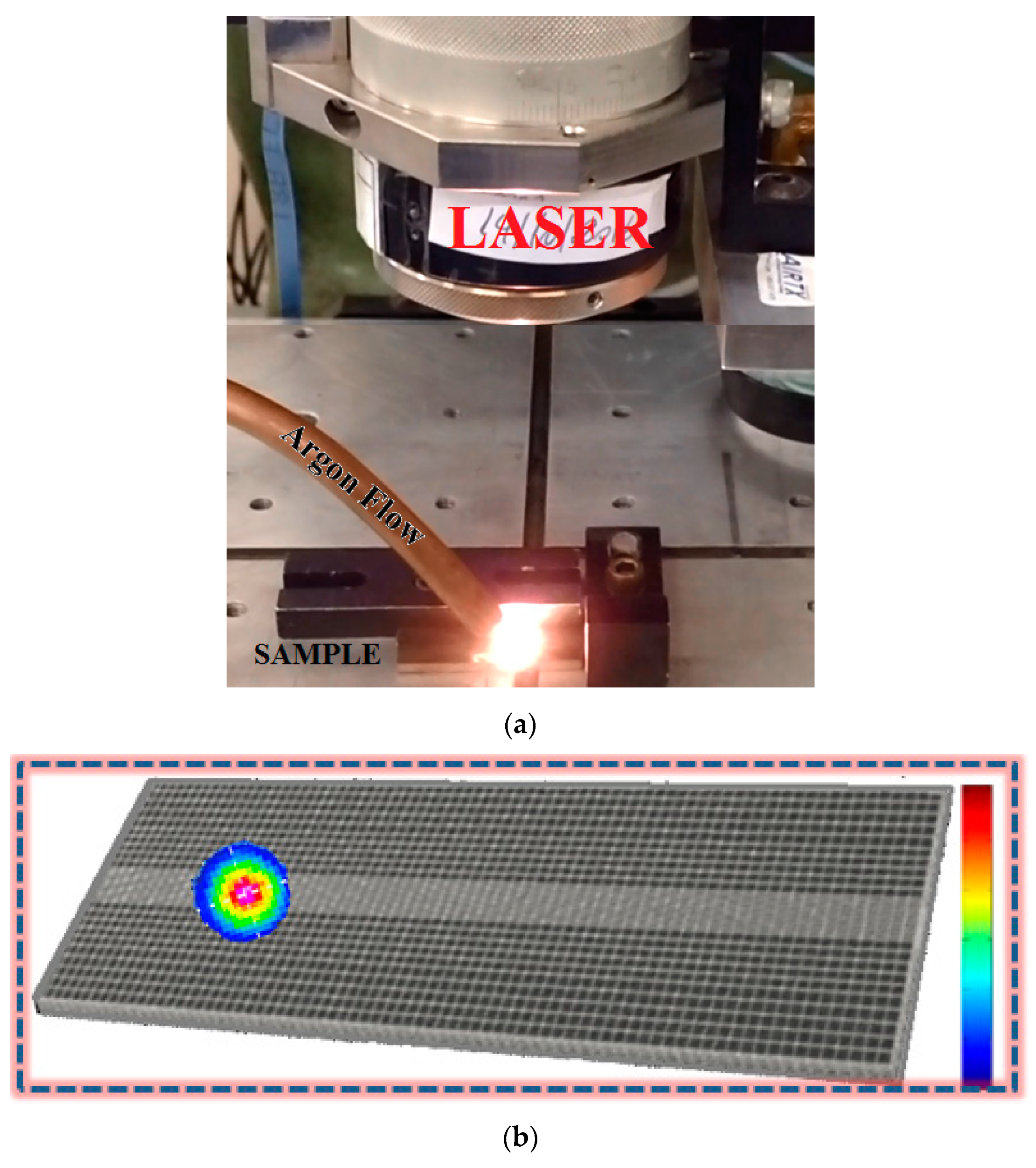
2.2. Laser Surface Melting (LSM)

The Yb (fiber) laser used 2.0 kW average power (IPG, Model YLR-2000) with an output fiber 50 µm in diameter and 5.0 m in length with a wavelength (λ) of 1070 nm and 2 mm spot size. A fiber coupling unit connected to a working fiber of 100 µm in diameter and 10 m in length was used in the welding processes. The working fiber was connected to an optical collimator forming the beam coupling system. This laser was housed in an aluminum processing cabin (3.0 m3) equipped with process auxiliary inert gas systems. The process head was coupled to a computer-controlled XYZ table driven by stepper motors, with a controlled velocity between 1.0 and 160 mm/s; the X-axis at 430 mm and Y-axis at 508 mm both had a resolution of 5.0 µm. A vertical Z-axis with a stroke of 215 mm and a resolution of 1.0 µm was incorporated into the table. The process head, characterized by a focal length of 160 mm, produced a 100 μm diameter laser beam. The welding head was also connected to the cooling-system hoses, the inert process gas system against oxidation, and gases to protect the optics against any splashing. The inert gas used in this project was argon. The configuration and scheme of this process are in Figure 1. Table 2 provides the parameters of the laser surface melting (LSM) processes used in this study on NiTi samples, where the nomenclature LSM 71 means the power used (700 W) and the scan speed (10 mm/s) of the LSM process, for instance. Table 2 also provides the argon flow, focal distance, and laser fluence values.
Figure 2 presents macrostructural images of surface views of the samples before and after the laser surface melting process in all conditions. The best surface finishing of the material was observed for 35 J/mm2.

2.3. Microstructural Characterization

Visible light (optical) and scanning electron microscopy (SEM) were performed to characterize the microstructure of the alloy. Optical microscopy (OM) was performed using an optical microscope (Zeiss model Axio_Imager a2M., Stockholm, Sweden), equipped with Axiocam ICC3 video camera and digitizer board connected to a computer with AxioVision 4.8.2 SP2 software (Stockholm, Sweden). For SEM, an electronic microscope (model VEGA3 TESCAN., Brno, Czech Republic) was used, with secondary electron detectors and microanalysis system by energy dispersive spectroscopy (EDS) from Oxford Instruments (Oxfordshire, Abingdon, UK). The samples were prepared to facilitate observation of their microstructure, making the surface specular for the subsequent chemical attack and revealing the microstructure. The sample preparation procedure involved cutting steps using a low speed ISOMET BUEHLERTM (Lake Bluff, IL, USA) 4000 with a diamond edged disc and cold resin inlay; sanding with grain sizes ranging from 120 to 1200 mesh, and automatic polishing with model METPREP-3ALLIED (Metprep Ltd., Coventry, UK) using 1 μm and 0.3 colloidal silica. X-ray diffraction was carried out using a diffractometer (SEIFERT-RAYFLEX., Nuremberg, Germany) model URD 65, using Cu Kα radiation (λ = 1.54178 Å). The acceleration was 20 kV, and the current was 30 mA. In the detector, 1 mm slots were mounted both horizontally and vertically. The reading time was 0.6 s with a pitch of 0.01° in the interval 2θ between 20 and 90°.

2.4. Mechanical Tests

A nanoindenter (Anton Paar NHT3., Graz, Austria) was used to provide low loads with depth measurements on the nanometer scale to measure hardness and modulus of elasticity, as well as creep. International standards ASTM E254 and ASTM E384 were used. Diamond tip, Berkovich type, maximum load 25 mN, and 10 s pause were the parameters used to analyze the hardness values and modulus of elasticity. The distances between consecutive indentations varied from 50 to 300 μm depending on different thicknesses of melted zone (MZ), heat-affected zone (HAZ), and base metal (BM). Maps of the hardness distribution in the longitudinal section were obtained through microindentation using an automated Durascan 50 (Emcotest., Kuchl, Austria) to map the hardness distribution in a preselected area. Software controlled the distribution of the indentation points respecting the distance from the edge and the spacing between indentations specified by the operator. The mean microhardness and modulus of elasticity value were calculated by averaging five tested points.

3. Results and Discussions

The micrographs in Figure 3 obtained by SEM illustrate the microstructure of the reference material (HT) with a crystalline structure of austenitic monophasic B2-NiTi. The transformations that occurred in the solid state in the HAZ, such as grain growth, the formation of intermetals and recrystallization are visible in Figure 3b–e. Figure 3a shows the equiaxed grains for the heat-treated (HT) sample with an average size of DHT = 35 μm in diameter and with darker points of titanium carbide (TiC). After the fusion process with pre-established parameters for the laser surface melting (LSM), such as power and scanning speed, the fusion zone (FZ) and the heat-affected zone (HAZ) could be inferred. In Figure 3b–e, the FZ and HAZ are separated by a well-defined fusion boundary. Due to different fluence values and the thermal cycles, the grains exhibited different sizes. Micrographs in Figure 3b–e reveal a dendritic structure in the FZ due to rapid solidification and a recrystallized, equiaxed grain structure in the HAZ. For the fluence of 17.5 J/mm2, the average grain size was about 15% smaller than those found in the HT samples. For the fluences from 22.5 to 45 J/mm2, the laser surface melting increased the grain sizes from 3% to 15%. The observed solidification structure can be explained by the fast solidification theory, which establishes four parameters to control the microstructure found in the FZ temperature gradient (ΔT), cooling time (t), crystal growth rate (CGR), and alloy composition (wt.%) [34]. The ratio between growth rate and temperature gradient governs the solidification mode. Those results demonstrated that the laser surface melting technique can be suitable for directly changing the morphology. Although the energy density was large and the cooling procedure was very fast, the low thermal conductivity of the NiTi alloy caused the temperature gradient to spread very little, so that the base metal cooled the HAZ [38,39].
Figure 4 presents grain growth related to different laser fluence values, and Figure 5 shows the comparative diagram of laser fluence vs. depth and width dimensions of the molten pool. The width and depth of the melted pool were directly affected by the laser fluence. The desired geometry of the molten pool could be achieved by controlling the optimization of the laser parameters.
The geometry of the cross-section of Figure 6a–c exhibits a “U”-shaped molten pool. These semi-spherical shapes, in most cases, indicate proper mixing of all materials in the liquid and semi-viscous states due to the flow forces acting within the molten pool. Under fluence 45 J/mm2, shown in Figure 6d, the penetration cord was deeper, indicating a transition regime from conduction to keyhole; therefore, the 45 J/mm2 (900 watts by 10 mm/s) was a sufficient condition in which the material would melt, followed by vaporization. The vaporization rebound in the 45 J/mm2 formed a depression zone whose dimensions depended on the physical properties of the material and the beam intensity. The vapor channel received multiple reflections of the beam within it, which was associated with higher bead depth, splashing material losses, and preferential volatilizing of some elements.
The EDS analysis, presented in Table 3, revealed the values of chemical composition for the FZ and HAZ. As a consequence the transformation temperature behavior, transformation temperatures are very sensitive to the proportion of Ni and Ti. The superelasticity and shape memory of the resulting material is directly related to Ti/Ni ratio; thus, the Ti/Ni ratio is the key aspect in nitinol manufacture. For most applications, the transformation temperature needs to be controlled at ± 5 °C, which means that the alloy composition should be controlled within ± 0.05%. Therefore, this effect implies a very restrictive chemical tolerance for the alloy production and surface treatment, in which changing the alloy composition by just 1% results in a 100 °C difference in the transformation temperature of the alloy [40].
According to Table 3, the lowest Ti/Ni ratio was 0.790 for the FZ of the 22.5 J/mm2 fluence and the highest value of Ti/Ni ratio was 0.853 from 35 J/mm2. This was related to preferential volatilization of Ni, which results in local changes in functional characteristics. Similar behavior was observed in another study [41] that correlated the laser pulse and preferential Ni volatilization, as well as conduction mode, which appears to be the best choice for processing such material. Figure 7 correlates the Ni content and laser fluence. Other studies [29,34] have confirmed that TiO2 passive films are directly enhanced by greater Ti/Ni surface ratio because of the high oxidation of titanium. In addition, the formation of intermetallic phases (Ni4Ti3, Ni3Ti2, Ni3Ti, Ti2Ni) is directly related to Ti/Ni ratio and is sensitive to heat treatment [29,34].
All conditions of laser fluence presented a similar behavior: the reduction of Ni content. However, the FZ of the 22.5 J/mm2 exhibited closer chemical composition than the samples without laser treatment, due to precipitation of intermetallic Ni-rich phases (Ni3Ti), confirmed by X-ray diffractogram as shown in Figure 8.
After the laser surface treatment, intermetallic formation often occurs, such as Ti2Ni, Ni4Ti3, and Ni3Ti, and these formations depend on the chemical composition, the temperature gradient, and the thermomechanical history. The HT condition presented monophasic B2 and TiC. For the fluence values of 22.5 and 35 J/mm2, the respective eutectoid reactions NiTi → NiTi + Ni3Ti and NiTi → NiTi + Ti2Ni occurred, as illustrated in Figure 8. In studies with low and medium laser fluence [38], martensite phase formation has been observed. However, all samples studied in this present work, with high levels of laser fluence and Ni volatilization (Figure 7), did not present any formation of martensite phases, because this formation not only depends on the chemical composition, but also the temperature gradient and the thermomechanical history.
The mechanical tests of micro- and nanoindentation are fundamentally important to understand the performance of the NiTi material after surface treatment with high laser fluence. Hardness values are calculated in different ways. Figure 9a,b presents Vickers indentations, in which their hardness was calculated after loading, and Figure 9c–f presents the Berkovich nanoindentation, in which their hardness was calculated with the loaded indenter.
Figure 10 presents the hardness values obtained from the Berkovich nanoindentation tests in the FZ as well as the HAZ and BM for all different conditions of laser fluence. The condition 35 J/mm2, in Figure 10d, exhibited the highest values of hardness due to its hard intermetallic Ti2Ni phases. Other conditions presented behaviors similar to the HT condition, with an average hardness of 370 HV, due to its mixtures of Ni-rich and Ti-rich phases. Although Ti2Ni precipitation occurred for the 35 J/mm2, the TiC precipitation in the FZ decreased as a result of solubilization of carbon from the TiC in the matrix, as shown in Figure 5c. This phenomenon was observed not only for 35 J/mm2, but for all conditions of laser fluence, due to the high fluence laser treatment.
Figure 11 presents the two-dimensional (2D) hardness map obtained from Vickers microindentations. Those results are according to the ones presented in Figure 10. Therefore, hard intermetallic precipitated phases, such as Ti2Ni, enhanced the surface hardness of FZ and HAZ, as well as the surface hardness of BM without grain recrystallization. Despite the agreement of the behavior found by the different hardness measurement techniques, the higher values found for the microindentations tests were directly related to the superelastic effect in the projected area.
The superelastic behavior of distinct zones (WZ, HAZ, and BM) are represented by load–displacement curves in nanoindentation tests as evidenced by the depth recovery rate (Figure 12). The superelastic properties were affected by high laser fluence, noticeably changing the depth recovery ratio due to differences on displacement axis.
Figure 13 presents Young’s modulus of the different regions studied in this paper. Increased average modulus of the FZ tended to increase the laser fluence, and the highest value was obtained from the condition 35 J/mm2 (80 GPa), which was 14.3% higher than the reference sample (HT = 70 GPa). In general, this depends on the chemical composition, as well as the temperature gradient and the thermomechanical history.

4. Conclusions

The following conclusions can be made after studying the relationship between laser surface melting treatment with high fluence values in Ni-rich NiTi alloys:
(a)
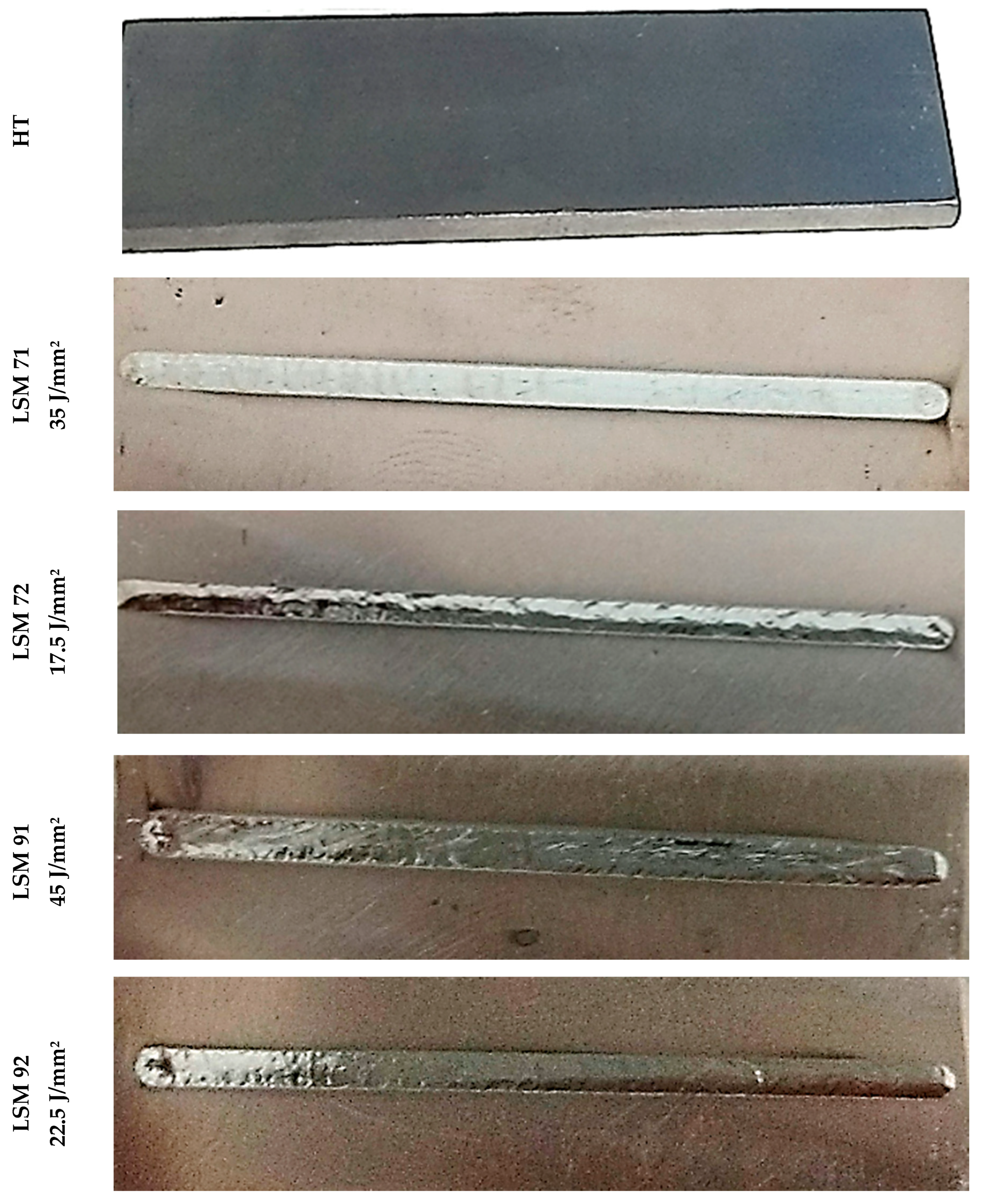
The greatest surface finishing of the fusion zone was observed at the condition of 35 J/mm2.
(b)
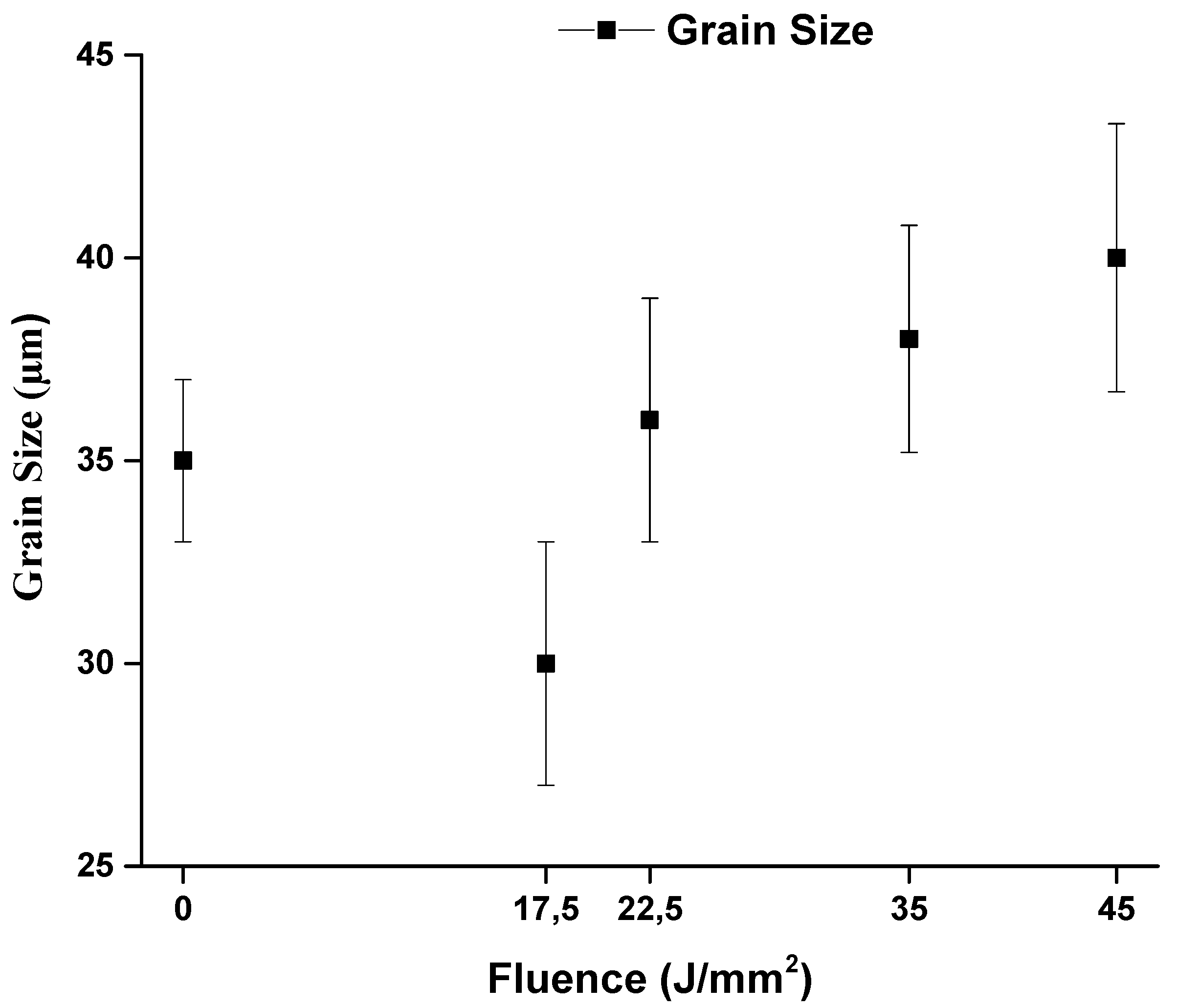
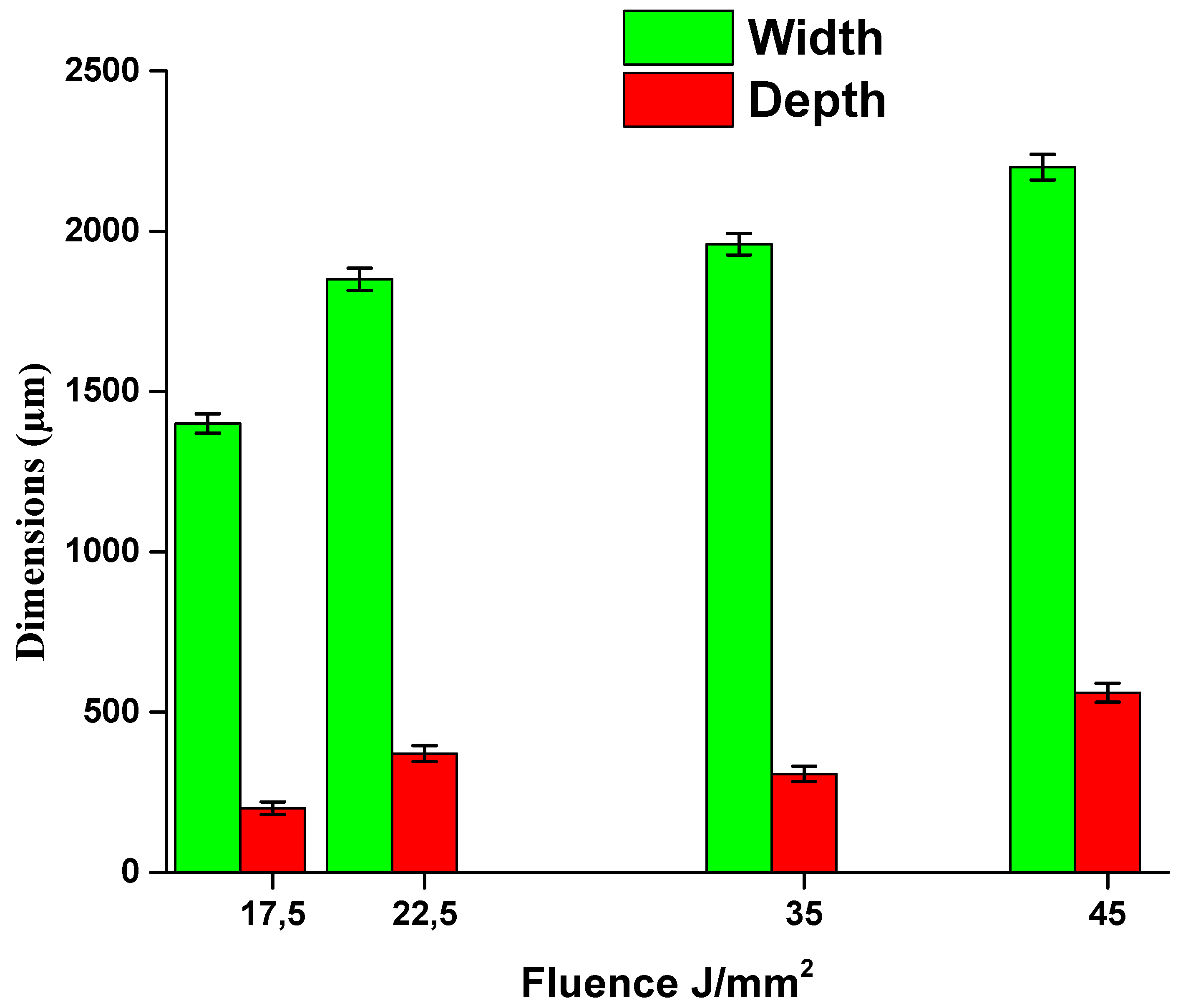
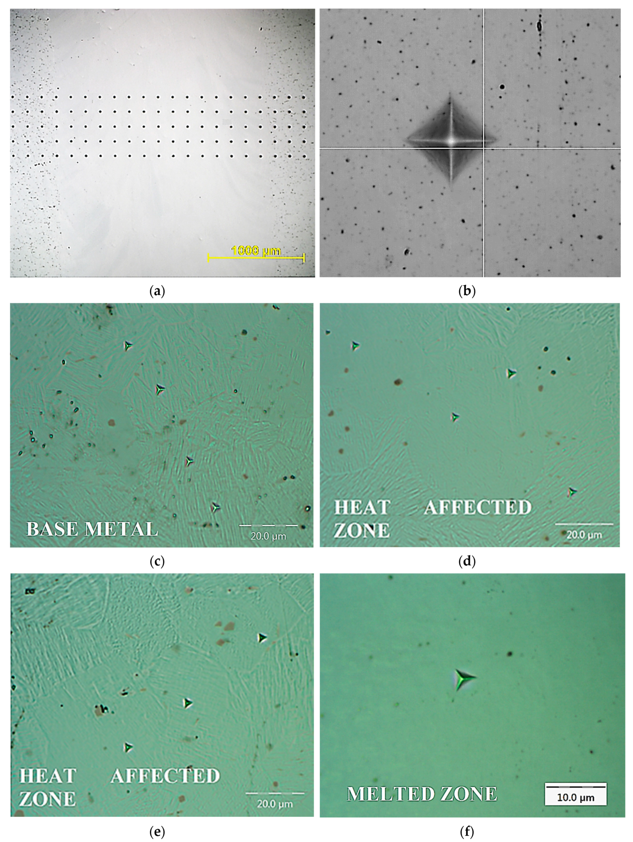
Three well-defined regions (FZ, HAZ, BM) could be observed. The laser fluence directly affected the dimensions of grain size as well as the width and depth of the melted pool. The geometry of the molten pool could be controlled by the optimization of the laser parameters.
(c)
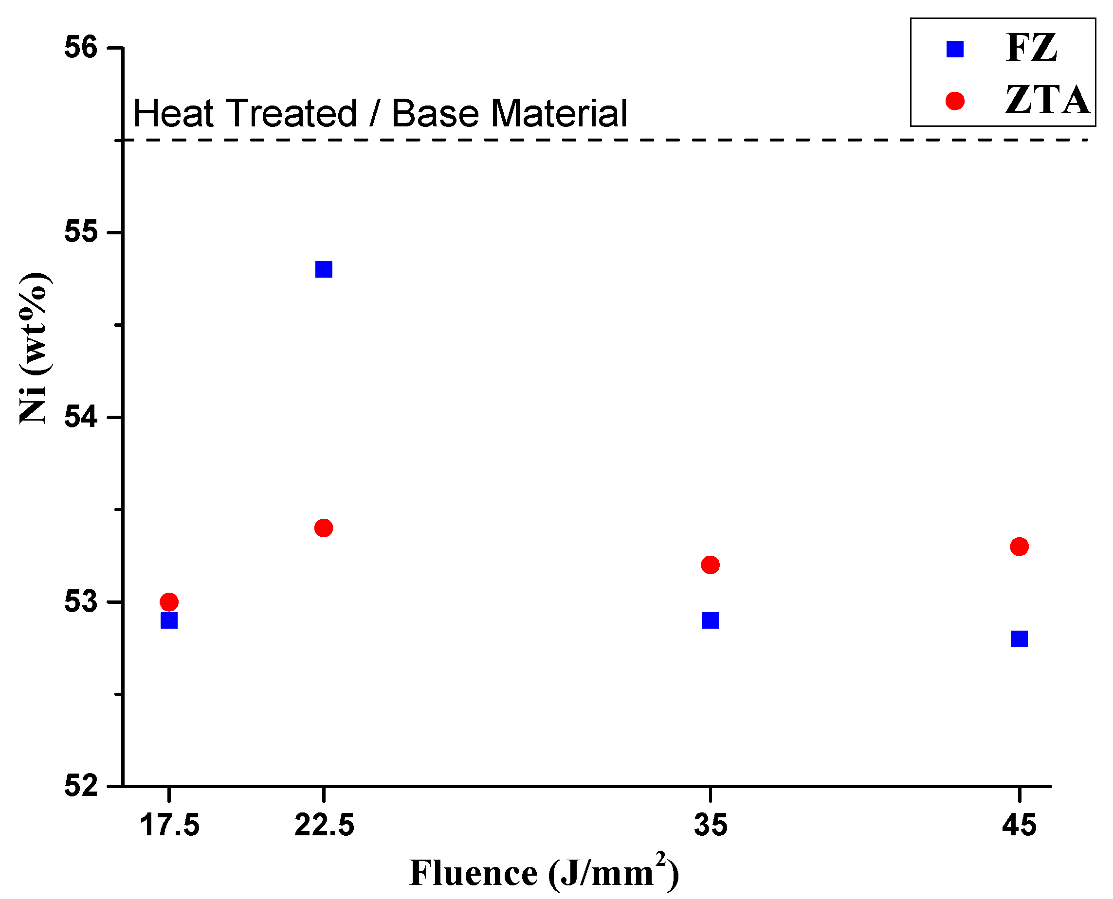
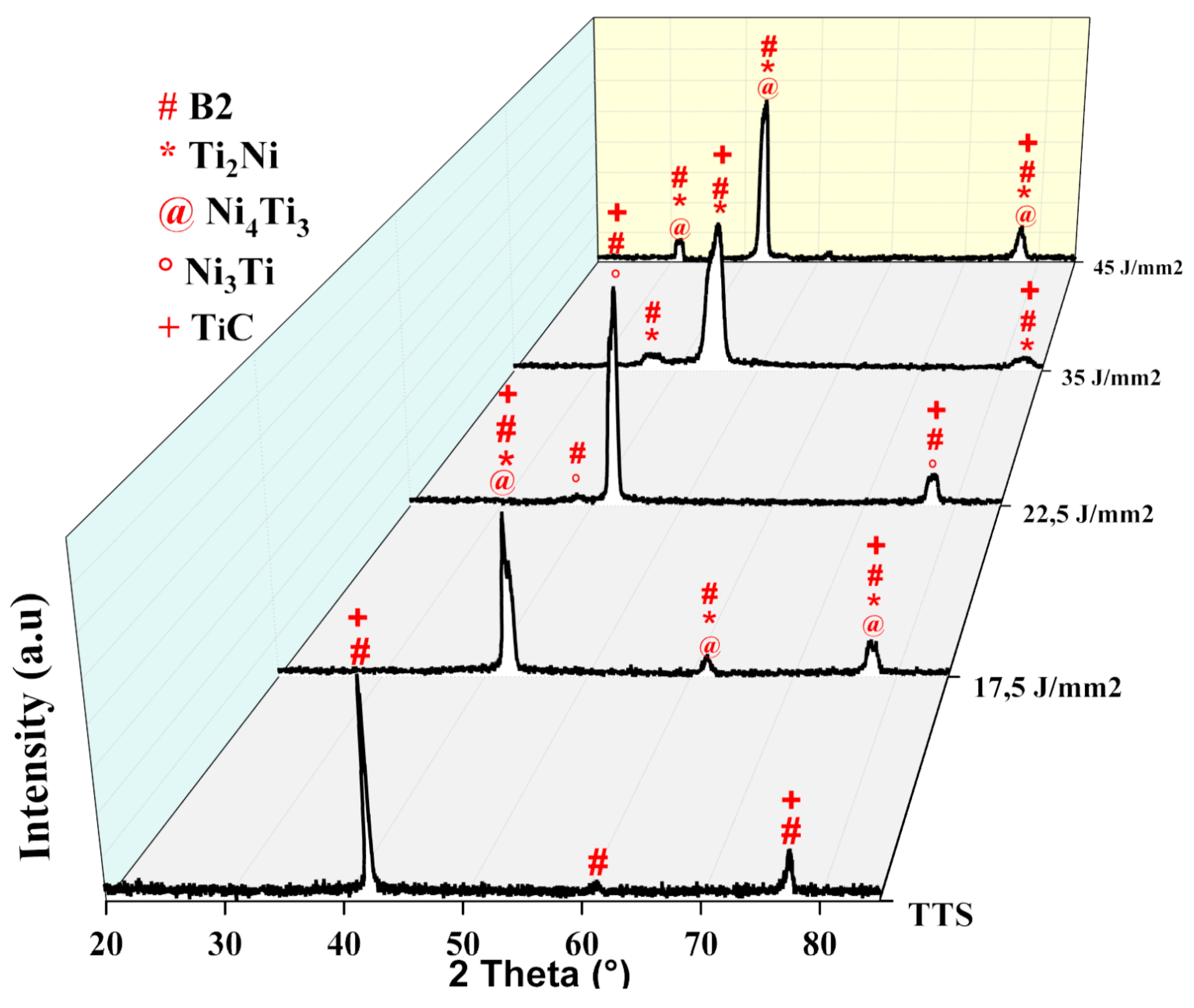
High laser fluence values caused preferential volatilization of nickel, dynamic precipitation of intermetallic phases like Ti2Ni, Ni3Ti, and Ni4Ti3, and solubilization of TiC in the matrix, which leads to grain refinement.
(d)
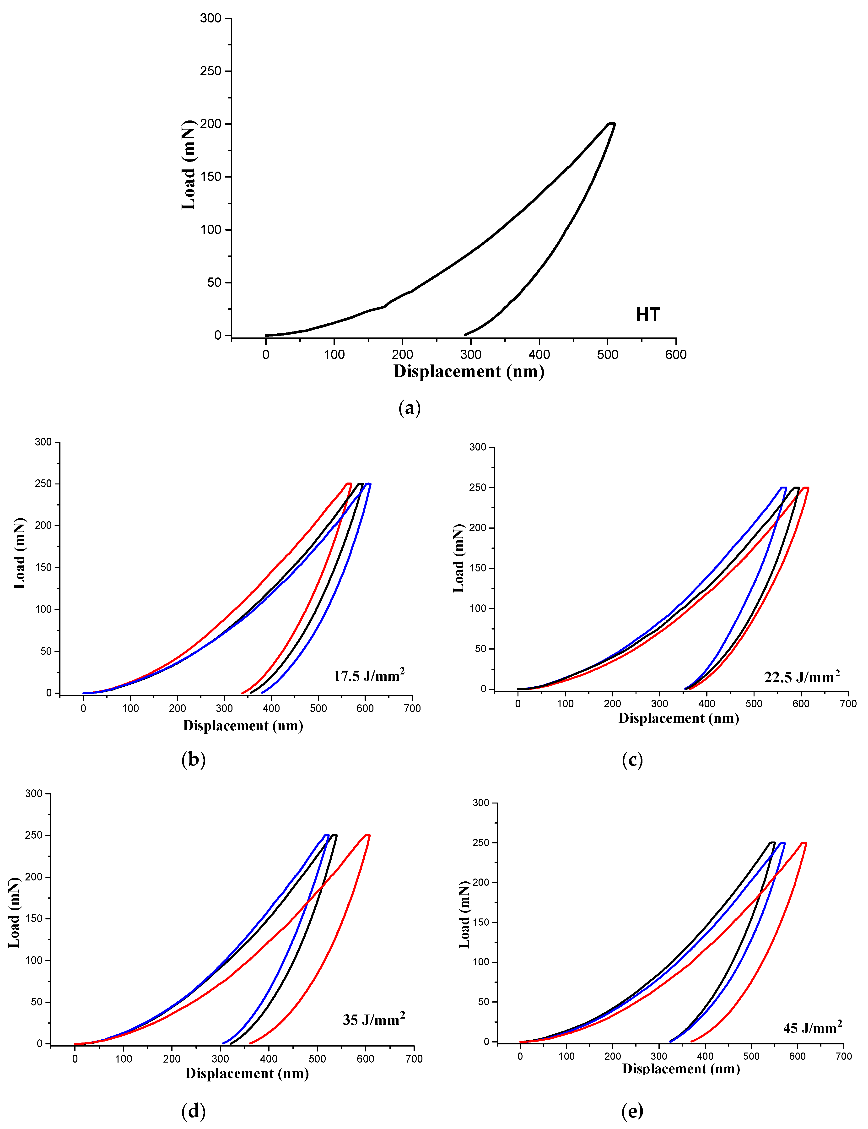
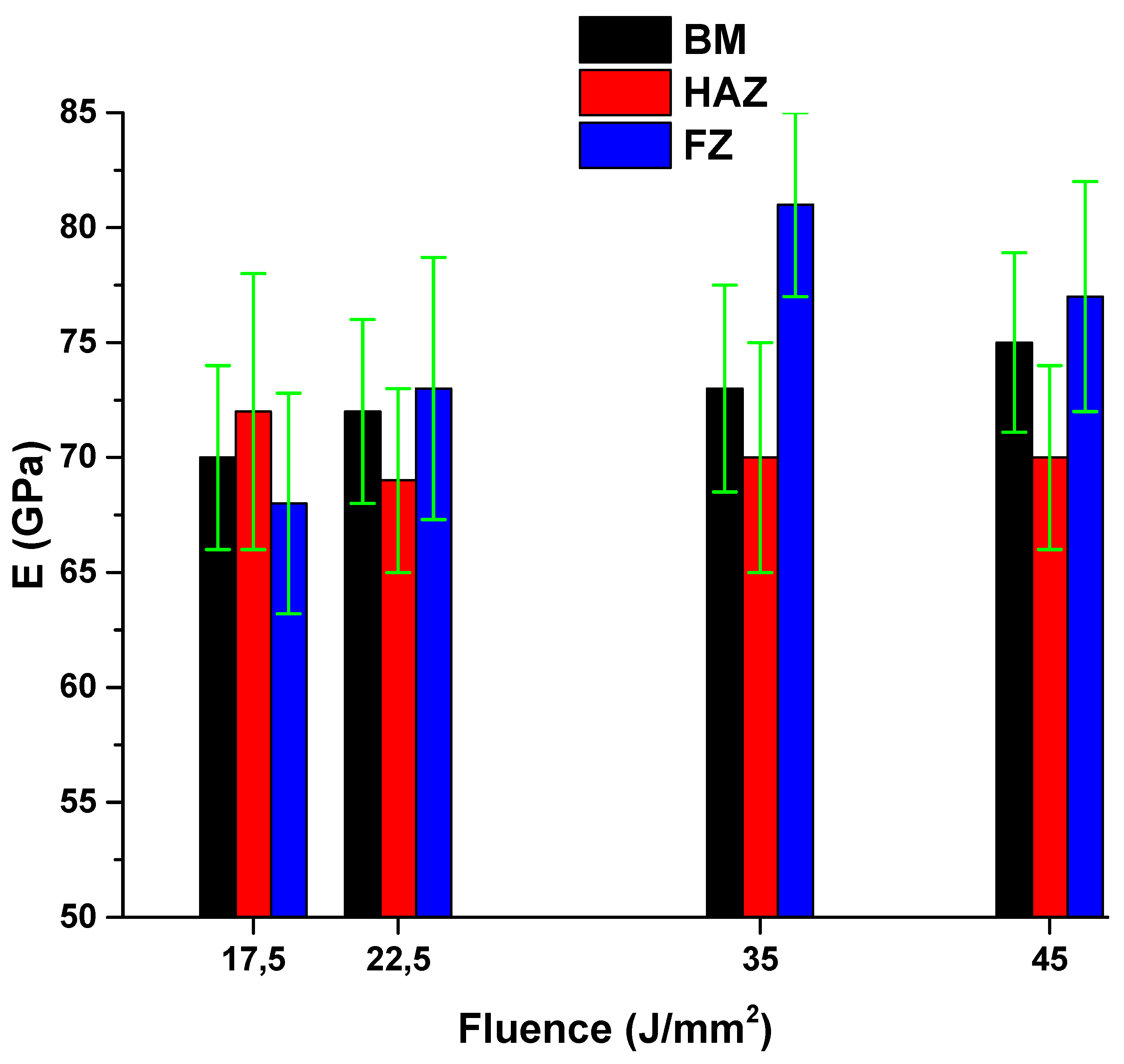
High laser fluence proved to be a suitable technique to enhance mechanical properties like hardness and Young’s modulus.

Author Contributions

Conceptualization, D.D., O.S.S., M.S.F.L. and M.M.d.S.; data curation, D.D. and O.S.S.; formal analysis, D.D., W.A. and M.M.d.S.; funding acquisition, D.D. and M.M.d.S.; investigation, D.D., W.A. and M.M.d.S.; methodology, D.D., O.S.S., M.S.F.L. and M.M.d.S.; project administration, D.D. and M.M.d.S.; resources, D.D.; software, D.D., O.S.S. and W.A.; supervision, D.D. and M.M.d.S.; validation, D.D. and M.M.d.S.; visualization, D.D.; writing—original draft, D.D. and O.S.S.; writing—review & editing, D.D.

Funding

This research received no external funding.

Acknowledgments

The authors acknowledge CAPES and FAPESP for financial support.

Conflicts of Interest

The authors declare no conflict of interest.

References

  1. Duerig, T.; Pelton, A.; Stöckel, D. An overview of nitinol medical applications. Mater. Sci. Eng. A 1999, 273–275, 149–160. [Google Scholar] [CrossRef]
  2. Pan, G.; Balagna, C.; Martino, L.; Spriano, S. Microstructure and transformation temperatures in rapid solidified Ni–Ti alloys. Part I: The effect of cooling rate. J. Alloys Comp. 2014, 589, 628–632. [Google Scholar] [CrossRef]
  3. Wu, M.H.; Schetky, L.M. Industrial applications for shape memory alloys. In Proceedings of the International conference on shape memory and superelastic technologies, Pacific Grove, CA, USA, 30 April–4 May 2000; Memry Corporation: Brookfield, CT, USA, 2000; pp. 171–182. [Google Scholar]
  4. Furuya, Y. Design and material evaluation of shape memory composites. J. Intell. Mater. Syst. Struct. 1996, 7, 321–330. [Google Scholar] [CrossRef]
  5. Leo, D.J.; Weddle, C.; Naganathan, G.; Buckley, S.J. Vehicular applications of smart material systems. In Smart Structures and Materials 1998: Industrial and Commercial Applications of Smart Structures Technologies; Society of Photo Optical: San Diego, CA, USA, 1998; pp. 106–116. [Google Scholar]
  6. Stoeckel, D. Shape memory actuators for automotive applications. Mater. Des. 1990, 11, 302–307. [Google Scholar] [CrossRef]
  7. Bil, C.; Massey, K.; Abdullah, E.J. Wing morphing control with shape memory alloy actuators. J. Intell. Mater. Syst. Struct. 2013, 24, 879–898. [Google Scholar] [CrossRef]
  8. Hartl, D.J.; Lagoudas, D.C. Aerospace applications of shape memory alloys. Proc. Inst. Mech. Eng. Part G J. Aerosp. Eng. 2007, 221, 535–552. [Google Scholar] [CrossRef]
  9. Humbeeck, J.V. Non-medical applications of shape memory alloys. Mater. Sci. Eng. A 1999, 273, 134–148. [Google Scholar] [CrossRef]
  10. McDonald Schetky, L. Shape memory alloy applications in space systems. Mater. Des. 1991, 12, 29–32. [Google Scholar] [CrossRef]
  11. Sun, L.; Huang, W.M.; Ding, Z.; Zhao, Y.; Wang, C.C.; Purnawali, H.; Tang, C. Stimulus-responsive shape memory materials: a review. Mater. Des. 2012, 33, 577–640. [Google Scholar] [CrossRef]
  12. Kohl, M. Shape memory microactuators (microtechnology and MEMS). In Microsystem Technologies, 1st ed.; Springer: Berlin, Germany, 2010. [Google Scholar]
  13. Kahny, H.; Huffz, M.A.; Heuer, A.H. The TiNi shape-memory alloy and its applications for MEMS. J. Micromechanics Microengineering 1998, 8, 213–221. [Google Scholar] [CrossRef]
  14. Kheirikhah, M.; Rabiee, S.; Edalat, M. A review of shape memory alloy actuators in robotics. In Robot Soccer World Cup; Ruiz-del-Solar, J., Chown, E., Plöger, P., Eds.; Springer: Berlin, Germany, 2011; pp. 206–217. [Google Scholar]
  15. Sreekumar, M.; Nagarajan, T.; Singaperumal, M.; Zoppi, M.; Molfino, R. Critical review of current trends in shape memory alloy actuators for intelligent robots. Ind. Robot Int. J. 2007, 34, 285–294. [Google Scholar] [CrossRef]
  16. Petrini, L.; Migliavacca, F. Biomedical applications of shape memory alloys. J. Metall. 2011, 2011, 15. [Google Scholar] [CrossRef]
  17. Song, C. History and current situation of shape memory alloys devices for minimally invasive surgery. Open Med. Devices, J. 2010, 2, 24–31. [Google Scholar] [CrossRef]
  18. Morgan, N.B. Medical shape memory alloy applications–the market and its products. Mater. Sci. Eng. A 2004, 378, 16–23. [Google Scholar] [CrossRef]
  19. Machado, L.G.; Savi, M.A. Medical applications of shape memory alloys. Braz. J. Med. Biol. Res. 2003, 36, 683–691. [Google Scholar] [CrossRef]
  20. Mantovani, D. Shape memory alloys: properties and biomedical applications. JOM 2000, 52, 36–44. [Google Scholar] [CrossRef]
  21. Langenhove, L.V.; Hertleer, C. Smart clothing: a new life. Int. J. Clothing Sci. Technol. 2004, 16, 63–72. [Google Scholar] [CrossRef]
  22. Lecce, L.; Concilio, A. Shape Memory Alloy Engineering for Aerospace, Structural and Biomedical Applications; Elsevier: Amsterdam, The Netherlands, 2015. [Google Scholar]
  23. Hao, W.; Zhou, L.; Sun, Y.; Shi, P.; Liu, H.; Wang, X. Treatment of patella fracture by claw-like shape memory alloy. Arch. Orthop. Trauma Surg. 2015, 135, 943–951. [Google Scholar] [CrossRef]
  24. Kwok, C.T.; Man, H.C.; Cheng, F.T.; Lo, K.H. Developments in laser-based surface engineering processes: With particular reference to protection against cavitation erosion. Surf. Coatings Technol. 2016, 291, 189–204. [Google Scholar] [CrossRef]
  25. Steen, W.M.; Mazumder, J. Laser Material Processing, 4th ed.; Springer: Berlin, Germany, 2010. [Google Scholar]
  26. Lo, K.H.; Cheng, F.T.; Man, H.C. Laser transformation hardening of AISI 440C martensitic stainless steel for higher cavitation erosion resistance. Surf. Coat. Technol. 2003, 173, 96–104. [Google Scholar] [CrossRef]
  27. Menci, G.; Demir, A.G.; Waugh, D.G.; Lawrence, J.; Previtali, B. Laser surface texturing of β-Ti alloy for orthopaedics: Effect of different wavelengths and pulse durations. Appl. Surf. Sci. 2019, 489, 175–186. [Google Scholar] [CrossRef]
  28. Cui, Z.; Man, H.; Yang, X. The corrosion and nickel release behavior of laser surface-melted NiTi shape memory alloys in Hanks solution. Surf. Coat. Technol. 2005, 192, 347–353. [Google Scholar] [CrossRef]
  29. Chan, C.W.; Hussain, I.; Waugh, D.G.; Lawrence, J.; Man, H.C. Effect of laser treatment on the attachment and viability of mesenchymal stem cell responses on shape memory NiTi alloy. Mater. Sci. Eng. C 2014, 42, 254–263. [Google Scholar] [CrossRef] [PubMed]
  30. Ghasemi, R.; Shoja-razavi, R.; Mozafarinia, R.; Jamali, H. Laser glazing of plasma-sprayed nanostructured yttria stabilized zirconia thermal barrier coatings. Ceram. Int. 2013, 39, 9483–9490. [Google Scholar] [CrossRef]
  31. Fu, B.; Feng, K.; Li, Z. Study on the effect of Cu addition on the microstructure and properties of NiTi alloy fabricated by laser cladding. Mater. Lett. 2018, 220, 148–151. [Google Scholar] [CrossRef]
  32. Mahamood, R.M.; Akinlabi, E.T.; Shukla, M.; Pityana, S. Scanning velocity influence on microstructure, microhardness and wear resistance performance of laser deposited Ti6Al4V/TiC composite. Mater. Des. 2013, 50, 656–666. [Google Scholar] [CrossRef]
  33. Kaspar, J.; Bretschneider, J.; Jacob, S.; Bonß, S.; Winderlich, B.; Brenner, B. Microstructure, hardness and cavitation erosion behaviour of Ti–6Al–4V laser nitrided under different gas atmospheres. Surf. Eng. 2007, 23, 99–106. [Google Scholar] [CrossRef]
  34. Chan, C.; Man, H.; Yue, T. Effects of process parameters upon the shape memory and pseudo-elastic behaviors of laser-welded NiTi thin foil. Metall. Mater. Transact. A 2011, 42, 2264–2270. [Google Scholar] [CrossRef]
  35. Oliveira, J.P.; Miranda, R.M.; Braz Fernandes, F.M. Welding and Joining of NiTi Shape Memory Alloys: A Review. Prog. Mater. Sci. 2017, 88, 412–466. [Google Scholar] [CrossRef]
  36. Mehrpouya, M.; Gisario, A.; Elahinia, M. Laser welding of NiTi shape memory alloy: A. review. J. Manuf. Process. 2018, 31, 162–186. [Google Scholar] [CrossRef]
  37. Chakraborty, R.; Datta, S.; Shahid Raza, M.; Saha, P. A comparative study of surface characterization and corrosion performance properties of laser surface modified biomedical grade Nitinol. Appl. Surf. Sci. 2019, 469, 753–763. [Google Scholar] [CrossRef]
  38. Gong, W.-H.; Chen, Y.-H.; Ke, L.M. Microstructure and properties of laser micro welded joint of TiNi shape memory alloy. Trans. Nonferrous Met. Soc. China 2011, 21, 2044–2048. [Google Scholar] [CrossRef]
  39. Mohd Jani, J.; Leary, M.; Subic, A.; Gibson, M.A. A review of shape memory alloy research, applications and opportunities. Mater. Des. 2014, 56, 1078–1113. [Google Scholar] [CrossRef]
  40. Mwangi, J.W.; Nguyen, L.T.; Bui, V.D.; Berger, T.; Zeidler, H.; Schubert, A. Nitinol manufacturing and micromachining: A review of processes and their suitability in processing medical-grade nitinol. J. Manuf. Process. 2019, 38, 355–369. [Google Scholar] [CrossRef]
  41. Michael, A.; Zhou, Y.N.; Yavuz, M.; Khan, M.I. Modelling the alloy element composition change in NiTi achieved through laser induced vaporization. Mater. Chem. Phys. 2019, 231, 87–94. [Google Scholar] [CrossRef]
Figure 1. (a) Laser surface melting configuration and (b) laser surface melting configuration scheme.
Metals 09 01268 g001
Figure 2. Surface finishing view before and after the laser melting process in different conditions.
Metals 09 01268 g002
Figure 3. SEM images before (a) and after laser treatment (b) 17.5 J/mm2 laser fluence, (c) 22.5 J/mm2 laser fluence, (d) 35 J/mm2 laser fluence, and (e) 45 J/mm2 laser fluence. Highlighting the fusion zone, fusion boundaries, and heat-affected zone.
Metals 09 01268 g003
Figure 4. Comparative diagram of grain size with laser fluence.
Metals 09 01268 g004
Figure 5. Comparative diagram of laser parameter fluence on the dimensions of width and depth of the melt pool of NiTi.
Metals 09 01268 g005
Figure 6. Microstructures of a cross-section of NiTi samples showing the width and depth of the melted pool: (a) 17.5 J/mm2, (b) 22.5 J/mm2, (c) 35 J/mm2, (d) 45 J/mm2.
Metals 09 01268 g006
Figure 7. Comparative graphic of the correlation between Ni content and laser fluence.
Metals 09 01268 g007
Figure 8. X-ray diffractogram of all conditions, evidencing phases, and intermetallic precipitates.
Metals 09 01268 g008
Figure 9. Images of the mechanical tests performed in different regions studied in this work. In (a) is the microindentations covering from side to side of the melted zone to the 2D graph, (b) presented a singles Vickers microindentations in surface, (c) Berkovich nanoindentations in base metal, (d) and (e) Berkovich nanoindentations in HAZ and (f) Berkovich nanoindentations in melted zone.
Metals 09 01268 g009
Figure 10. Berkovich indentation hardness as a function of the distance from the center of melting in the conditions: (a) Heat Treated, (b) 17.5 J/mm2, (c) 22.5 J/mm2, (d) 35 J/mm2, (e) 45 J/mm2.
Metals 09 01268 g010
Figure 11. 2D surface graphic of Vickers microhardness from all NiTi samples in the conditions: (a) Heat Treated, (b) 17.5 J/mm2, (c) 22.5 J/mm2, (d) 35 J/mm2, (e) 45 J/mm2.
Metals 09 01268 g011
Figure 12. The nanoindentation load vs. displacement depth curves for the conditions studied in this work in the conditions: (a) Heat Treated, (b) 17.5 J/mm2, (c) 22.5 J/mm2, (d) 35 J/mm2, (e) 45 J/mm2. Blue lines for fusion zone, red lines for HAZ, and black lines for base metal.
Metals 09 01268 g012
Figure 13. Comparative diagram of elasticity modulus from different regions of the NiTï samples.
Metals 09 01268 g013
Table 1. Nominal composition in atomic percentages and weight of material obtained by vacuum induction melting (VIM).
Ni (wt.%) C (wt.%)O (wt.%)Ti (wt.%)
55.500.0470.113244.66
Table 2. The parameters of the laser surface melting processes.
SamplePower (W)Speed Scan (mm/s)Argon (l/min)Δz (mm)FL (J/mm2)
LSM7170010181235.0
LSM7270020181217.5
LSM9190010181245.0
LSM9290020181222.5
Table 3. Chemical composition and Ti/Ni ratio comparison of the material before and after laser surface modification *.
Fluence Ni (wt%)Ti (wt%)C(wt%)O (wt%)Ti/Ni
17.5 J/mm2FZ
HAZ
52.9
53
44.9
44.9
1.2
1.2
1.0
0.9
0.848
0.847
22.5 J/mm2FZ
HAZ
54.8
53.4
43.3
44.3
1.1
1.5
0.8
0.8
0.790
0.829
35 J/mm2FZ
HAZ
52.9
53.2
45.1
44.3
1.1
1.8
0.9
0.8
0.853
0.833
45 J/mm2FZ
HAZ
52.8
53.3
45.0
44.6
1.2
1.1
1.0
0.9
0.852
0.837
* Ti/Ni ratio 0.804 for base metal or bulk material.

