Abstract
Al–Mg–Si alloys are usually formed into their final shape by rolling or extrusion. After extrusion, the aluminium profiles are usually straightened, causing the material to be subjected to a small plastic deformation. This study demonstrates the positive effect on strength that can be obtained from such small deformation levels or from only elastically straining the material. Elastic straining of a lean Al–Mg–Si alloy, when performed immediately after solution heat treatment, enhances the material yield strength after artificial ageing to T6. Transmission electron microscopy shows that this effect can be attributed to a higher number density and finer dispersion of the age-hardening precipitate needles. Furthermore, introducing a small plastic deformation of 1% after solution heat treatment results in a comparable strength increase to elastically straining the material. In this case, however, the strength increase is due to the increased dislocation density, which compensates for a lower density of precipitate needles. Finally, by combining plastic deformation with a succeeding elastic strain, we demonstrate how elastic strain can cause an on-set of dislocation cell formation in this material.
1. Introduction
Age-hardenable Al–Mg–Si alloys are becoming more and more specialised depending on their intended purpose. Due to challenging material specifications, it is imperative to understand every step of the process chain and how it may affect the final material properties. Products made from 6xxx aluminium alloys are usually shaped by either rolling or extrusion, and extruded profiles will usually be straightened in order to avoid any buckling or uneven features. The straightening procedure will induce some plastic deformation, usually of about 0.5–1%. In some products, like for example crash-boxes in cars, minute changes to the macroscopic properties can mean the difference between meeting the product requirements or not. It is therefore of great importance to understand how such small deformation levels, and even elastic strain levels, may affect the final properties of these alloys.
One of the characteristics of the aluminium 6xxx series, is that the alloys gain their strength from the formation of metastable precipitates during artificial ageing (AA), usually performed in a temperature range between 150 °C and 200 °C [1,2]. All the metastable precipitates in the Al–Mg–Si system have one main coherency direction, parallel to the <100> Al directions. As a consequence, the precipitates assume the shape of needles, rods or laths elongated in one of these three directions. The increased strength is a consequence of the precipitates’ ability to obstruct dislocation movement [3]. Depending on the precipitate type and size, the precipitates can be either sheared or looped by dislocations [3,4].
The alloying agents gain sufficient atomic mobility for clustering at room temperature due to a quenched-in supersaturation of vacancies [5]. By artificially ageing the material afterwards, GP zones form and grow. By increasing the artificial ageing temperature, or duration of ageing, precipitate phases change from coherent matrix-like to semi-coherent, and finally become incoherent equilibrium phases. The precipitation sequence is generally given as follows [6]:
SSSS ⇒ Atomic clusters [5,7,8]⇒ GP zones [9]⇒” [10,11]⇒’ [12,13], U1 [14], U2 [15], B’ [16]⇒ [17], Si [18]
However, a vast range of alloying elements can be added to 6xxx alloys to alter the precipitate phases or number densities, and consequently the material properties [19,20]. Precipitate types are known to affect material strength, where GP zones and ″ in particular are phases associated with peak hardness [1,2]. The post-″ phases, ′, U1, U2 and B’, typically form upon over-aging, and their coarsened distribution in the matrix is associated with a loss of material strength [2,21]. U1, U2, and B’ are also known as types A, B and C, respectively, from [22]. Serizawa et al. have found evidence of two types of atomic clusters in this context, with the ability to either prevent or promote precipitate nucleation during subsequent aging [5]. It has been reported that storage at RT is beneficial for the formation of “good clusters” in the case of lean alloys (Mg + Si solute levels below 1 at%) [1,23,24].
If deformation is applied during natural ageing, a dramatic change in precipitation during artificial ageing may occur [25,26,27]. In such cases, precipitation preferentially occurs on dislocations, resulting in an inhomogeneous precipitate distribution. Since dislocations provide fast diffusion paths for the solute atoms, precipitation and growth processes are accelerated and peak hardness can be reached sooner. Because of the introduction of dislocations, the strength after artificial ageing of a deformed material can be higher, even if the net contribution to strength from precipitation may be reduced. Moreover, strain in the pre-yield regime can cause inelastic deformation, often referred to as micro-plasticity [28]. That is, local plastic transitions which do not lead to any measurable deformation can still occur at elastic strain levels [29]. The effect of micro-plasticity on strength and precipitation in aluminium alloys has, to the best of the authors’ knowledge been subject to little investigation.
In this study a lean 6060 alloy has been subjected to different combinations of elastic strain and 1% plastic deformation during natural ageing. Tensile test results are connected to results from transmission electron microscopy (TEM) investigations of precipitation and dislocation densities. By thoroughly investigating the material’s microstructure and connecting it to the macroscopic properties, we aim to clarify the effects that may arise after extrusion of lean 6xxx alloys.
2. Materials and Methods
2.1. Pre-Treatment and Tensile Specimens
The alloy was provided by Hydro Aluminium as extruded profiles with a rectangular cross section with dimensions 5 mm × 40 mm. The billets were heated to 540 °C in order to dissolve all Mg2Si-particles, then rapidly cooled to 500 °C just prior to extrusion. Profiles were extruded from Ø 95 mm diameter extrusion billets in a 800 ton laboratory press. The profiles were quenched in water just after the die exit in order to eliminate formation of new (Mg, Si)-particles. The extruded profiles have a recrystallized grain structure, with an average grain size of approximately 100 m. The chemical composition of the experimental alloy is given in Table 1.

Table 1.
Chemical composition of the Al6060 alloy in wt%.
Standard flat tensile specimens were machined from the extruded profiles, see dimensions in Figure 1. The middle area of the extruded profile was chosen to avoid edge effects. All tensile testing was done according to the recommended specifications in [30].
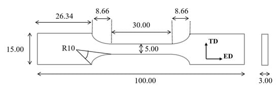
Figure 1.
Tensile specimen geometry used in the experiments. All numbers are given in mm. Extrusion direction (ED) and transverse direction (TD) are indicated by arrows.
2.2. Elastic Strain and Plastic Deformation
Five different thermo-mechanical processing routes were performed, see Figure 2. All processing routes included a solution heat treatment at 500 °C for 5 min in a salt bath, followed by water-quenching to room temperature, then natural ageing for 24 h and artificial ageing in an oil bath kept at 160 °C for 26 h. The heat treatment described in Figure 2a is the reference condition.
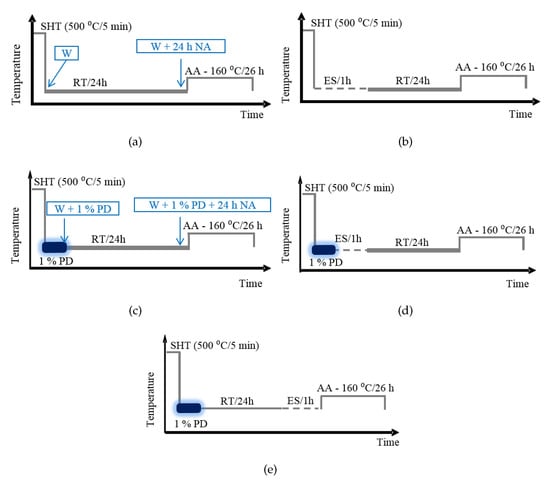
Figure 2.
Description of the five processing routes. All routes include a solution heat treatment (SHT) at 500 °C for 5 min in a salt bath, followed by water-quench (W) to room temperature (RT), natural ageing (NA) for 24 h and artificial ageing (AA) at 160 °C for 26 h. (a) The reference material; (b) elastic straining (ES) was applied at 50% of the material yield strength for 1 h directly after SHT. The material was then naturally aged and artificially aged; (c) 1% plastic deformation (PD) was applied directly after SHT. The material was then naturally aged and artificially aged; (d) 1% plastic deformation was applied directly after SHT, immediately followed by elastic straining for 1 h at 50% of the material yield strength. The material was then naturally and artificially aged; (e) 1% plastic deformation was applied directly after SHT, followed by natural ageing and then 1 h elastic straining at 50% of the material yield strength. Finally the material was artificially aged. The text-boxes with arrows indicate the four conditions presented in Figure 3. Water quench to room temperature is denoted ‘W’.
Elastic straining of the material was carried out at stress-levels corresponding to 50% of the yield strength at room temperature. A low nominal strain rate of 10 s was used, and the material was kept at this stress level for 1 h, see illustrations in Figure 2b,d,e.
1% plastic deformation was applied at room temperature immediately after water quench from SHT, see Figure 2c, similar to an industrial process. The nominal strain rate used for 1% plastic deformation was 10 s. The combinations of plastic deformation and elastic strain are illustrated in Figure 2d,e. The true stress–logarithmic strain curves were obtained by a standard tensile testing set-up in an MTS810 hydraulic test machine operated at an initial nominal strain rate of 10 s, with a 25 mm extensometer.
2.3. TEM
TEM specimens were cut from the centre of the tensile specimens, see Figure 1. The specimens were sliced perpendicular to the extrusion direction, polished to a thickness of 70–150 m, and electropolished using a Struers Tenu-Pol 5 electropolishing machine. The electrolyte consisted of one part nitric acid and two parts methanol. The solution was kept at temperatures ranging from −25 °C to −30 °C by adding liquid nitrogen.
A Philips CM30 transmission electron microscope, operated at 150 kV, was used to acquire all TEM images. Calibrated TEM film-negatives were used to obtain measurements of average precipitate needle lengths, cross sections, number densities and volume fractions. A Gatan parallel electron energy loss spectrometer (PEELS) was used to determine the thickness of the imaged areas. The method used for acquiring the quantitative results can be found in detail in [2]. The quantitative results for average needle lengths are based on measurements of at least 1000 needles for each condition, while the average cross sections are calculated based on about 150 cross sections for each condition. All TEM micrographs were acquired along a <001>Al zone axis. Several grains were investigated for each condition to ensure representative statistics.
3. Results
3.1. Tensile Tests
In order to determine the effect of 1% plastic deformation before artificial ageing, tensile testing was done directly after water quenching the material and again after 24 h of natural ageing, see Figure 3. After water quenching the material, there is a significant increase in yield strength after introducing 1% plastic deformation. When further naturally ageing the material for 24 h, the effect of plastic deformation is still obvious, enhancing the strength of about 20 MPa compared to the reference. When comparing the yield strength of the materials before and after natural ageing, the unstrained reference increases by about 20 MPa, while the plastically deformed material increases by 15 MPa.
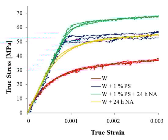
Figure 3.
True stress as a function of logarithmic strain for: The reference material directly after water quench (red curve), and after 24 h of natural ageing (yellow curve). 1% plastic strain after water quench (blue curves) and after 1% plastic strain and 24 h natural ageing (green curves). See Figure 2a,c for the thermo-mechanical treatment.
Further tensile testing was performed for all five processing routes after 26 h of artificial ageing, and are presented in Figure 4. The tensile test results, showing stress as a function of logarithmic strain, are presented in Figure 4. Considering Figure 4 the tensile results can be divided into three relative classes of strength. Lower strength: The reference sample (Figure 2). Medium strength: The material with only elastic strain and the material with only 1% plastic deformation (Figure 2b,c, respectively). Higher strength: The two combinations of 1% plastic deformation and elastic strain (Figure 2d,e, respectively). The combination of elastic strain and plastic deformation increases the strength by 12–15 MPa relative to the reference. Surprisingly, only subjecting the material to elastic strain also leads to increased strength.
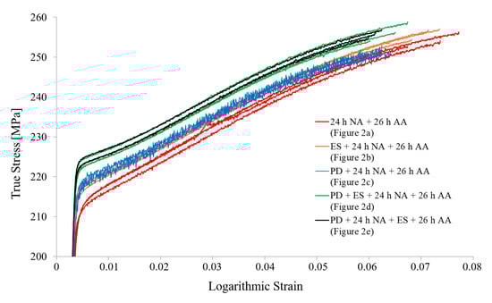
Figure 4.
True stress as a function of logarithmic strain for the heat treatments shown in Figure 2. Three parallels were performed for each condition. NA: Natural ageing, AA: Artificial ageing, ES: Elastic straining for 1 h at 50% of yield strength, PD: 1% plastic deformation.
3.2. TEM Results
TEM micrographs from each of the five processing routes after 26 h artificial ageing are presented in Figure 5. All five conditions exhibit the well-known double-line contrast associated with precipitate-matrix interface strain. Any differences between the five conditions were not obvious from inspection by eye, except for the presence of dislocations in the plastically deformed samples. The quantified precipitate parameters based on TEM and (P)EELS thickness measurements are given in Table 2. Here it can be seen that elastically straining the material (without plastic deformation) results in a refinement of the precipitates. The number density has increased, while the length and cross section has decreased slightly. The three processing routes including plastic deformation shows the opposite effect, where the number density has decreased slightly compared to the reference.
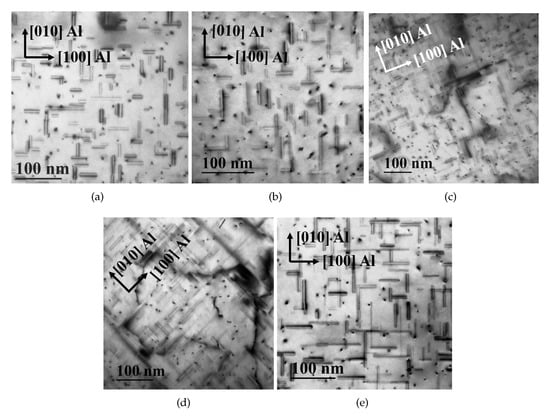
Figure 5.
TEM images from each processing route after artificial ageing, taken along the <001>Al zone axis. See arrows indicating crystal directions in each image. (a) Reference sample (Figure 2a); (b) elastic strain before natural ageing (Figure 2b); (c) 1% plastic strain (Figure 2c). Dislocations can be observed in several areas; (d) 1% plastic strain and elastic strain before natural ageing (Figure 2d). An example of the dislocation cells frequently found; (e) 1% plastic strain, then natural ageing, then elastic straining (Figure 2e). The microstructure in (d,e) is very similar, see Table 2, dislocation cells and precipitates are emphasized in (d,e), respectively.
Table 2.
Precipitate parameters after artificial ageing for the conditions in Figure 2. The volume fraction of precipitates has a 95% probability of being within the intervals.
For further analysis, a lower magnification was used to compare the reference material, Figure 2a, the material subjected to 1% plastic deformation, Figure 2c and the material subjected to both elastic strain and plastic deformation, Figure 2d. Representative TEM micrographs from each condition at the same magnification are given in Figure 6. The micrographs were taken from areas with thicknesses of about 220 nm.
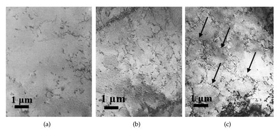
Figure 6.
Low magnification TEM micrographs from representative areas in the sample material after artificial ageing. (a) The unstrained reference material; (b) plastically deformed material by 1%; (c) 1% plastic deformation and elastic strain. The arrows in (c) point out some of the tangled dislocation cell walls present in the imaged area.
Figure 6a shows a relatively low dislocation density in the reference material, with no visible dislocation cell formation. As expected, after applying 1% plastic deformation the dislocation density has increased to such an extent that it is visible by eye. For the material which was subjected to both plastic deformation and elastic strain, there is a further increase in dislocation density accompanied by a significant cell formation of tangled dislocations, see Figure 6c.
The different precipitates that may occur at homogeneous and heterogeneous nucleation sites are presented separately in Figure 7. In Figure 7a the white arrows point out ” cross sections, which are the main phase found in dislocation-free areas. A higher fraction of ’ U1, U2 and B could be observed after the material was subjected to 1% plastic deformation. Phases associated with over-aged materials are often observed on dislocation lines, an example of a B’ precipitate is shown in Figure 7b. B’ has a characteristic periodicity of 1 nm, with an 11° angle to <100>Al.
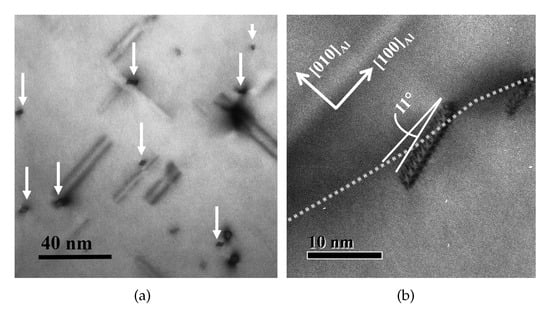
Figure 7.
(a) A dislocation-free area exhibiting ” cross sections in the reference material, indicated by white arrows; (b) B’ precipitate on a dislocation line in the plastically deformed material. The dislocation is indicated by white dashed lines. The two images were taken along a <001>Al crystal direction.
4. Discussion
The effect of plastic deformation is evident when applied directly after water quenching the material, leading to an increase in material strength by 20 MPa, see Figure 3. This effect is well-known, and can be attributed to work-hardening, where dislocations are introduced to the material. During natural ageing, clustering is allowed to commence; however, the strength difference between the two tested materials is less than what it was directly after SHT. When the material has been deformed, precipitation preferentially occurs on dislocations [25]; additionally, in-situ observations have shown that such heterogeneous precipitation commences at an earlier stage than homogeneous nucleation [31]. It seems as if the undeformed material has a higher strength contribution from clustering, which infers that there are less clusters present in the plastically deformed material after 24 h of natural ageing.
The strength after artificial ageing in Figure 4 shows a clear effect by only elastically straining the material. By investigating the microstructure of all five conditions, the material subjected to elastic strain had the highest precipitate number density after artificial ageing, see statistics in Table 2. By rapidly cooling the material after the solution heat treatment, the solid solution is supersaturated, including both solute and vacancies. This consequently leaves the matrix in a very unstable state, yielding it likely to be more affected by mechanical processing. Here, elastic straining of the material results in a refinement of the precipitate distribution, consequently causing an increase in material strength, see Figure 4. Compared to the reference sample, the precipitate number density has increased by about 5000 needles per cubic m by elastically straining the material. As micro-plasticity is expected to occur also in the elastic regime, it is possible that part of the strength increase could be due to local introduction of dislocations [28]. Locally increased dislocation densities should accelerate precipitate nucleation and growth in these confined areas [31], and possibly increase the occurrence of phases associated with over-ageing. However, since micro-plasticity is difficult to measure by tensile testing, elastic straining also seems to promote nucleation events or stabilise smaller clusters for further growth, consequently leading to a higher fraction of precipitate needles. The most frequently observed phase after elastically straining this material is the ” phase, see Figure 7, which is the meta-stable phase dominating at peak hardness in Al–Mg–Si alloys.
After artificial ageing, the material which was subjected to 1% plastic deformation exhibits a similar strength increase to the elastically strained material. In this case, however, it is the introduced dislocations contributing positively to strength, while the strength contribution from precipitation is slightly lowered, see Table 2. The increase in dislocation density is significant even at such a low deformation level and can be observed merely by eye in Figure 6. The precipitate phases observed on dislocation lines after 1% plastic deformation were similar to those reported for higher plastic deformation levels [25,26], see Figure 7. B’ ’ are, as mentioned in the introduction, typical precipitate phases associated with over-ageing. In short, plastic deformation causes an earlier on-set of precipitation, precipitates associated with over-ageing and a lowered precipitate number density.
The highest yield strength of the five processing routes was achieved for the two conditions combining elastic strain and plastic deformation, see Figure 2d,e. This result can according to Table 2 not be attributed to the contribution from precipitates only, as the precipitate distribution is slightly coarser compared to the other three conditions. TEM investigations at a lower magnification revealed an increased dislocation density, as for the material which was only plastically deformed. However, by combining elastic strain and plastic deformation, dislocation cell formation was observed for a major part of the grains, see Figure 6. This recovery process seems to be the only significant difference when comparing the microstructures after artificial ageing. Consequently, the formation of tangled dislocation cells must be due to the applied elastic strain after plastic deformation, in turn causing increased material strength, see Figure 4. The effect is not dependent on the time at which elastic strain is applied during natural ageing, as the results are similar for both 0 and 24 h. It is likely that the clusters which are present after 24 h of natural ageing are too small to pin dislocations, hence recovery is allowed to proceed during elastic straining. Since the initial defect structure in the material has been changed after 1% plastic deformation, it is likely that the mechanisms of micro-plasticity during elastic straining changes [28], causing “elastic strain” to initiate dislocation movement leading to the dislocation cell structures we observe in Figure 6 [32]. The cell-structure could in turn create a beneficial precipitate distribution during artificial ageing, causing the precipitates to grow in a somewhat cell-like structure. The strengthening effect by cyclic plasticity was described by Sun et al. [33], where cyclic deformation during natural ageing significantly enhances the strength of three aluminium alloys. They demonstrated that dislocation loops were present and atomic clusters were heterogeneously distributed throughout the material. It is likely that we are observing a somewhat similar effect in this study, where clustering is partly heterogeneous and dislocations become mobile during elastic straining. In the material which was subjected to cyclic deformation the precipitation free zones were absent, giving an additional positive effect on strength [33]. Strain accumulation is a steady process which tends to localise [34], and in many cases this occurs at the precipitation free zone (PFZ). The build-up of strain at the PFZ leads to material failure in this area [35,36]. As a consequence, the material should withstand higher stress levels if the PFZ were to be eliminated. Further investigation of the material in this study should be conducted to confirm the nature of the PFZs for these conditions.
In conclusion, elastic strain and small plastic deformation levels up to 1% seem to be beneficial for the final material strength of lean 6xxx alloys when performed during natural ageing. Consequently, the deformation which extruded profiles are subjected to during straightening should be positive for the final material strength.
5. Conclusions
The effects of 1% plastic deformation, elastic strain or a combination of the two have been investigated for an Al–Mg–Si alloy. Material strength has been correlated to TEM investigations of precipitate and dislocation distributions.
Subjecting the material to elastic strain at the beginning of natural ageing causes an increase in material yield strength. This increase was attributed to an increased precipitate number density of smaller semi-coherent ” needles. Applying 1% plastic deformation at the beginning of natural ageing resulted in similar strength enhancement due to the increased dislocation density in the material. The strength contribution from dislocations here compensates for the lowered contribution from precipitates.
The highest yield strength was obtained when combining plastic deformation with elastic strain during natural ageing. The strengthening effect was not dependent on when elastic strain was applied during natural ageing. The conditions with combined plastic deformation and elastic strain resulted in a slight decrease in precipitate number density, accompanied by dislocation cell formation. Consequently, elastic strain and small plastic deformation during natural ageing is beneficial for the material strength of lean Al–Mg–Si alloys. Straightening of extruded profiles should therefore cause enhanced material strength also after artificial ageing.
Author Contributions
Conceptualization, J.R.; Data curation, E.A.M. and C.D.M.; Formal analysis, E.A.M., C.D.M. and S.J.A.; Funding acquisition, J.R. and R.H.; Investigation, E.A.M., I.W. and C.D.M.; Methodology, I.W., K.O.P., J.R. and R.H.; Project administration, J.R. and R.H.; Supervision, C.D.M., S.J.A., J.R. and R.H.; Visualization, S.J.A.; Writing—original draft, E.A.M., I.W., C.D.M. and S.J.A.; Writing—review editing, E.A.M., I.W., C.D.M., K.O.P., J.R., B.H. and R.H.
Funding
This research was funded by BIA grant number 219371 and grant number 197405.
Acknowledgments
Hydro Aluminium and the Research Council of Norway are gratefully acknowledged for funding this research. All TEM work has been carried out at the NORTEM infrastructure, at the TEM Gemini Centre (NTNU), supported through grant no. 197405. Olaf Engler, Hydro Research and Development Bonn, is greatly acknowledged for sharing his expertise on this topic.
Conflicts of Interest
The authors declare no conflict of interest.
Abbreviations
The following abbreviations are used in this manuscript:
| AA | Artificial ageing |
| ES | Elastic strain |
| GP | Guinier–Preston |
| NA | Natural ageing |
| ND | Number density |
| PD | Plastic deformation |
| (P)EELS | Parallel electron energy loss spectroscopy |
| PFZ | Precipitation free zone |
| RT | Room temperature |
| SHT | Solution heat treatment |
| TEM | Transmission electron microscopy |
| W | Water quench |
References
- Marioara, C.; Andersen, S.; Jansen, J.; Zandbergen, H. The influence of temperature and storage time at RT on nucleation of the β′′ phase in a 6082 Al–Mg–Si alloy. Acta Mater. 2003, 51, 789–796. [Google Scholar] [CrossRef]
- Marioara, C.D.; Andersen, S.J.; Zandbergen, H.; Holmestad, R. The influence of alloy composition on precipitates of the Al–Mg–Si system. Metall. Mater. Trans. A 2005, 36, 691–702. [Google Scholar] [CrossRef]
- Misumi, K.; Kaneko, K.; Nishiyama, T.; Maeda, T.; Yamada, K.; Ikeda, K.I.; Kikuchi, M.; Takata, K.; Saga, M.; Ushioda, K. Three-dimensional characterization of interaction between beta” precipitate and dislocation in Al–Mg–Si alloy. J. Alloys Compd. 2014, 600, 29–33. [Google Scholar] [CrossRef]
- Poole, W.J.; Wang, X.; Lloyd, D.J.; Embury, J.D. The shearable–non-shearable transition in Al–Mg–Si–Cu precipitation hardening alloys: Implications on the distribution of slip, work hardening and fracture. Philos. Mag. 2005, 85, 3113–3135. [Google Scholar] [CrossRef]
- Serizawa, A.; Hirosawa, S.; Sato, T. Three-Dimensional Atom Probe Characterization of Nanoclusters Responsible for Multistep Aging Behavior of an Al-Mg-Si Alloy. Met. Mater. Trans. A 2008, 39, 243–251. [Google Scholar] [CrossRef]
- Edwards, G.A.; Stiller, K.; Dunlop, G.L.; Couper, M.J. The composition of fine-scale precipitates in Al–Mg–Si alloys. Mater. Sci. Forum 1996, 217–222, 713–718. [Google Scholar] [CrossRef]
- Murayama, M.; Hono, K. Pre-precipitate clusters and precipitation processes in Al-Mg-Si alloys. Acta Mater. 1999, 47, 1537–1548. [Google Scholar] [CrossRef]
- Torsæter, M.; Hasting, H.S.; Lefebvre, W.; Marioara, C.D.; Walmsley, J.C.; Andersen, S.J.; Holmestad, R. The influence of composition and natural aging on clustering during preaging in Al–Mg–Si alloys. J. Appl. Phys. 2010, 108, 073527. [Google Scholar] [CrossRef]
- Marioara, C.D.; Andersen, S.J.; Jansen, J.; Zandbergen, H.W. Atomic model for GP-zones in a 6082 Al–Mg–Si system. Acta Mater. 2001, 49, 321–328. [Google Scholar] [CrossRef]
- Zandbergen, H.W.; Andersen, S.J.; Jansen, J. Structure Determination of Mg5Si6 Particles in Al by Dynamic Electron Diffraction Studies. Science 1997, 277, 1221–1225. [Google Scholar] [CrossRef]
- Hasting, H.S.; Frøseth, A.G.; Andersen, S.J.; Vissers, R.; Walmsley, J.C.; Marioara, C.D.; Danoix, F.; Lefebvre, W.; Holmestad, R. Composition of β′′ precipitates in Al–Mg–Si alloys by atom probe tomography and first principles calculations. J. Appl. Phys. 2009, 106, 123527. [Google Scholar] [CrossRef]
- Cayron, C.; Buffat, P.A. Transmission electron microscopy study of the β′ phase (Al–Mg–Si alloys) and QC phase (Al–Cu–Mg–Si alloys): ordering mechanism and crystallographic structure. Acta Mater. 2000, 48, 2639–2653. [Google Scholar] [CrossRef]
- Vissers, R.; van Huis, M.A.; Jansen, J.; Zandbergen, H.W.; Marioara, C.D.; Andersen, S.J. The crystal structure of the β′ phase in Al–Mg–Si alloys. Acta Mater. 2007, 55, 3815–3823. [Google Scholar] [CrossRef]
- Andersen, S.; Marioara, C.; Vissers, R.; Frøseth, A.; Zandbergen, H. The structural relation between precipitates in Al-Mg-Si alloys, the Al-matrix and diamond silicon, with emphasis on the trigonal phase U1–MgAl2Si2. Mater. Sci. Eng. A 2007, 444, 157–169. [Google Scholar] [CrossRef]
- Andersen, S.J.; Marioara, C.D.; Frøseth, A.; Vissers, R.; Zandbergen, H.W. Crystal structure of the orthorhombic U2–Al4Mg4Si4 precipitate in the Al–Mg–Si alloy system and its relation to the β′ and β′′ phases. Mater. Sci. Eng. A 2005, 390, 127–138. [Google Scholar] [CrossRef]
- Vissers, R.; Marioara, C.D.; Andersen, S.J.; Holmestad, R. Crystal structure determination of the B’ phase in Al-Mg-Si alloys by combining quantitative electron difraction and Ab initio calculations. In Proceedings of the ICAA11, Aachen, Germany, 22–26 September 2008; Volume 2, pp. 1263–1269, ISBN 9978-3-527-32367-8. [Google Scholar]
- Bul’enkov, N.A.; Yakovenko, A.G.; Ul’yanikhina, O.M. X-ray diffraction study of the Mg2Si-Mg2Ge system. J. Struct. Chem. 1971, 11, 1059–1061. [Google Scholar] [CrossRef]
- Marioara, C.D.; Andersen, S.J.; Birkeland, A.; Holmestad, R. Orientation of silicon particles in a binary Al-Si alloy. J. Mater. Sci. 2008, 43, 4962–4971. [Google Scholar] [CrossRef]
- Saito, T.; Mørtsell, E.A.; Wenner, S.; Marioara, C.D.; Andersen, S.J.; Friis, J.; Matsuda, K.; Holmestad, R. Atomic Structures of Precipitates in Al–Mg–Si Alloys with Small Additions of Other Elements. Adv. Eng. Mater. 2018, 20, 1800125. [Google Scholar] [CrossRef]
- Andersen, S.J.; Marioara, C.D.; Friis, J.; Wenner, S.; Holmestad, R. Precipitates in aluminium alloys. Adv. Phys. X 2018, 3, 1479984. [Google Scholar] [CrossRef]
- Marioara, C.; Nordmark, H.; Andersen, S.; Holmestad, R. Post-β′′ phases and their influence on microstructure and hardness in 6xxx Al–Mg–Si alloys. J. Mater. Sci. 2006, 41, 471–478. [Google Scholar] [CrossRef]
- Matsuda, K.; Sakaguchi, Y.; Miyata, Y.; Uetani, Y.; Sato, T.; Kamio, A.; Ikeno, S. Precipitation sequence of various kinds of metastable phases in Al–1.0mass% Mg2Si–0.4mass% Si alloy. J. Mater. Sci. 2000, 35, 179–189. [Google Scholar] [CrossRef]
- Røyset, J.; Stene, T.; Sæter, J.A.; Reiso, O. The effect of intermediate storage temperature and time on the age hardening response of Al-Mg-Si alloys. Mater. Sci. Forum 2006, 519–521, 239–244. [Google Scholar] [CrossRef]
- Chang, C.; Wieler, I.; Wanderka, N.; Banhart, J. Positive effect of natural pre-ageing on precipitation hardening in Al–0.44 at % Mg 0.38 at % Si alloy. Ultramicroscopy 2009, 109, 585–592. [Google Scholar] [CrossRef] [PubMed]
- Teichmann, K.; Marioara, C.D.; Andersen, S.J.; Marthinsen, K. The Effect of Preaging Deformation on the Precipitation Behavior of an Al-Mg-Si Alloy. Metall. Mater. Trans. A 2012, 43, 4006–4014. [Google Scholar] [CrossRef]
- Teichmann, K.; Marioara, C.D.; Pedersen, K.O.; Marthinsen, K. The effect of simultaneous deformation and annealing on the precipitation behaviour and mechanical properties of an Al–Mg–Si alloy. Mater. Sci. Eng. A 2013, 565, 228–235. [Google Scholar] [CrossRef]
- Kolar, M.; Pedersen, K.O.; Gulbrandsen-Dahl, S.; Teichmann, K.; Marthinsen, K. Effect of Pre-Deformation on Mechanical Response of an Artificially Aged Al-Mg-Si Alloy. Mater. Trans. 2011, 52, 1356–1362. [Google Scholar] [CrossRef]
- Maaß, R.; Derlet, P. Micro-plasticity and recent insights from intermittent and small-scale plasticity. Acta Mater. 2018, 143, 338–363. [Google Scholar] [CrossRef]
- Zhang, X.; Xiong, J.; Fan, H.; Zaiser, M. Microplasticity and yielding in crystals with heterogeneous dislocation distribution. Model. Simul. Mater. Sci. Eng. 2019, 27, 074003. [Google Scholar] [CrossRef]
- ISO, EN. Metallic Materials—Tensile Testing—Part 1: Method of Test at Room Temperature; Standard, International Organization for Standardization: Geneva, Switzerland, 2016. [Google Scholar]
- Malladi, S.K.; Xu, Q.; van Huis, M.A.; Tichelaar, F.D.; Batenburg, K.J.; Yücelen, E.; Dubiel, B.; Czyrska-Filemonowicz, A.; Zandbergen, H.W. Real-Time Atomic Scale Imaging of Nanostructural Evolution in Aluminum Alloys. Nano Lett. 2014, 14, 384–389. [Google Scholar] [CrossRef]
- Yermolaeva, N.S.; Petinov, S.V.; Letova, T.I. FEM Modeling of the Aluminium Alloy Microplasticity. In Advanced Light Alloys and Composites; Springer: Dordrecht, The Netherlands, 1998; pp. 427–432. [Google Scholar] [CrossRef]
- Sun, W.; Zhu, Y.; Marceau, R.; Wang, L.; Zhang, Q.; Gao, X.; Hutchinson, C. Precipitation strengthening of aluminum alloys by room-temperature cyclic plasticity. Science 2019, 363, 972–975. [Google Scholar] [CrossRef]
- Morgeneyer, T.; Taillandier-Thomas, T.; Helfen, L.; Baumbach, T.; Sinclair, I.; Roux, S.; Hild, F. In situ 3-D observation of early strain localization during failure of thin Al alloy (2198) sheet. Acta Mater. 2014, 69, 78–91. [Google Scholar] [CrossRef]
- Morgeneyer, T.; Starink, M.; Wang, S.; Sinclair, I. Quench sensitivity of toughness in an Al alloy: Direct observation and analysis of failure initiation at the precipitate-free zone. Acta Mater. 2008, 56, 2872–2884. [Google Scholar] [CrossRef]
- Noell, P.; Carroll, J.; Hattar, K.; Clark, B.; Boyce, B. Do voids nucleate at grain boundaries during ductile rupture? Acta Mater. 2017, 137, 103–114. [Google Scholar] [CrossRef]


© 2019 by the authors. Licensee MDPI, Basel, Switzerland. This article is an open access article distributed under the terms and conditions of the Creative Commons Attribution (CC BY) license (http://creativecommons.org/licenses/by/4.0/).