Article

Development of New Cobalt-Free Maraging Steel with Superior Mechanical Properties via Electro-Pulsing Technology

Key Laboratory of Automobile Materials, Ministry of Education and School of Materials Science and Engineering, Jilin University, No. 5988 Renmin Street, Changchun 130022, China
*
Author to whom correspondence should be addressed.
Metals 2019, 9(12), 1299; https://doi.org/10.3390/met9121299
Submission received: 11 November 2019 / Revised: 25 November 2019 / Accepted: 26 November 2019 / Published: 2 December 2019

Abstract

:
The ductility of cobalt-free maraging steel is unsatisfactory because of the high content of Ti. Traditional heat treatment can not effectively improve the ductility of this kind steel. In this contribution, high-energy electro-pulsing is adopted in a T250 steel to solve this problem efficiently. It is found that the EPS treatment (electro-pulsing treatment under water-cooling condition) can accelerate the formation of retained austenite and nano stacking faults. Meanwhile, the microstructure is also refined by EPS treatment. Then, taking the EPS sample as the initial state, nano-reverted austenite combined with finer η-Ni3Ti precipitates are formed during EPA treatment (electro-pulsing treatment under air-cooling condition), compared with TA (traditional aging) treatment. The results of mechanical properties indicate that the strength and elongation are both enhanced by electro-pulsing treatment. Consequently, the electro-pulsing treatment can be a promising technology to devise cobalt-free maraging steel with better properties.

Graphical Abstract

1. Introduction

Since the 1960s, maraging steels have become irreplaceable materials in navigation and aviation fields by virtue of their excellent strength, toughness, and corrosion resistance [1,2,3]. Generally, compared with the quenched carbon steel, the maraging steels usually possess better ductility because of their high nickel content [4]. The pre-solution treatment will dissolve alloying elements into the matrix and after the water-cooling procedure, the matrix will be transformed into soft martensitic laths. Whereas, the soft matrix is only the foundation of the advanced mechanical properties of maraging steels and appropriate aging regime must be taken into force to guarantee a huge increment in strength. During the aging process, some inter-metallic compounds, such as Ni3Ti and Ni3Mo with hexagonal crystal structure will be formed, which will lead to the increment in strength [5]. In order to further enhance the strengthening effect, the element cobalt is added to maraging steel for the dynamic interaction between cobalt and molybdenum elements, i.e., the prior positions of molybdenum atoms will be occupied by cobalt atoms so that the precipitation of Ni3Mo compounds will be promoted [6]. However, accompanied with the gradually increased price and decreased resource reserve, cobalt is becoming a strategic resource around the global, and under this background, cobalt-free maraging steels are proposed [7].
Although the production costs of cobalt-free maraging steels decrease significantly, another problem also come out. To attain the same strength level as the maraging steels containing cobalt, more titanium is added to cobalt-free maraging steel [8]. In other words, less Ni3Mo and more Ni3Ti will be formed after aging regime is applied. Whereas, due to the higher c/a (lattice constant) value of Ni3Ti, the lattice coherence between Ni3Ti and the matrix is also lower than that between Ni3Mo and the matrix [9,10]. Thus, compared with maraging steels with cobalt content, the ductility of cobalt-free maraging steels is unsatisfactory. Recently, plenty of research has concentrated on the enhancement of ductility of maraging steels. Wang et al. [11] reported that during aging treatment, layered reverted austenites will be formed. As the reverted austenite can reduce the {111} fiber in martensite [12] and prevent the crack propagation during tensile deformation, the ductility of maraging steels will be improved [13,14]. However, the content of reverted austenites cannot be easily controlled so that the toughening (ductility improvement) effect is unstable. Besides, Pereloma [15] and Li [16] proposed that by rapid heating treatment, the strength is remarkably enhanced because of the formation of co-clusters and in contrast to maraging steels under traditional treatment, there is almost no loss in ductility. However, the R/b (radius/burgers vector) value of the co-cluster (known as the prior series of GP zone containing Mn, Ni, Ti, and Al) is very sensitive to treating parameters (temperature and treating procedure). If this value is higher than 15, there will be almost no toughening effect, and from the viewpoint of developing maraging steels with superior properties, no loss in ductility is insufficient. Moreover, Lu et al. [17] demonstrated that the ductility of maraging steels can be modified by the formation of Ni(Al,Fe) precipitations of which the lattice misfit is much lower than Ni3Ti. Whereas, the mass percentage of aluminum in this steel even reaches up to 3%. Such a high content of aluminum will lead to the increment in viscosity of molten steel, and the production cost will also increase. On the other hand, the grain refinement is considered to be the most effective method to toughening maraging steels. Unfortunately, there exist some problems for traditional austenitic grain (γ) refinement technology of maraging steels. Firstly, some severe plastic deformation technology, such as equal channel angular process (ECAP) [18,19] and high pressure torsion (HPT) can effectively reduce the grain (γ) size. However, a large amount of crystal defects will also be introduced so that the toughening effect is weakened. Then, even though the cyclic γ↔α′ transformation can also refine the grains (γ), there will exist intergranular oxidation because the high content of titanium enriched at the unstable grain boundaries, and so, the effect ductility improvement will be weakened. Finally, for recrystallization of maraging steels, not only the processing is time consuming, but also the parameters (temperature and deformation amount) are rigorous [20]. As a result, a new and more efficient toughening method is urgently needed for maraging steels.
Currently, as a rapid and effective treating technology, high-energy electro-pulsing processing has been widely utilized in many fields, such as structural relaxation in amorphous alloys [21], self-repairing of damage crack [22] and microstructural refinement [23]. For industrial manufacturing, the electro-pulsing current is also applied on electro-plastic drawing [24] and auxiliary molding of Ni-based alloys [25]. For steels, many studies have demonstrated the obviously improved strength and ductility induced by electro-pulsing current [26,27]. Moreover, our previous works also indicated that some substructures, such as sub-grains, nano-twins, and clusters, which are hard to be formed in steels by traditional treating strategy and beneficial for the ductility, can be obtained via electro-pulsing treatment [28,29]. In other words, the electro-pulsing treatment could be a suitable method for the ductility enhancement of maraging steels.
Thus, this work is aimed at the gradually optimization of solution and aging treatment of T250 steel by the comparison between traditional heat treatment and electro-pulsing heat treatment. Besides, the microstructure-property relationship of T250 steels under different treatment will also be closely investigated. It is expected to develop cobalt-free maraging steels with superior properties more efficiently.

2. Experimental

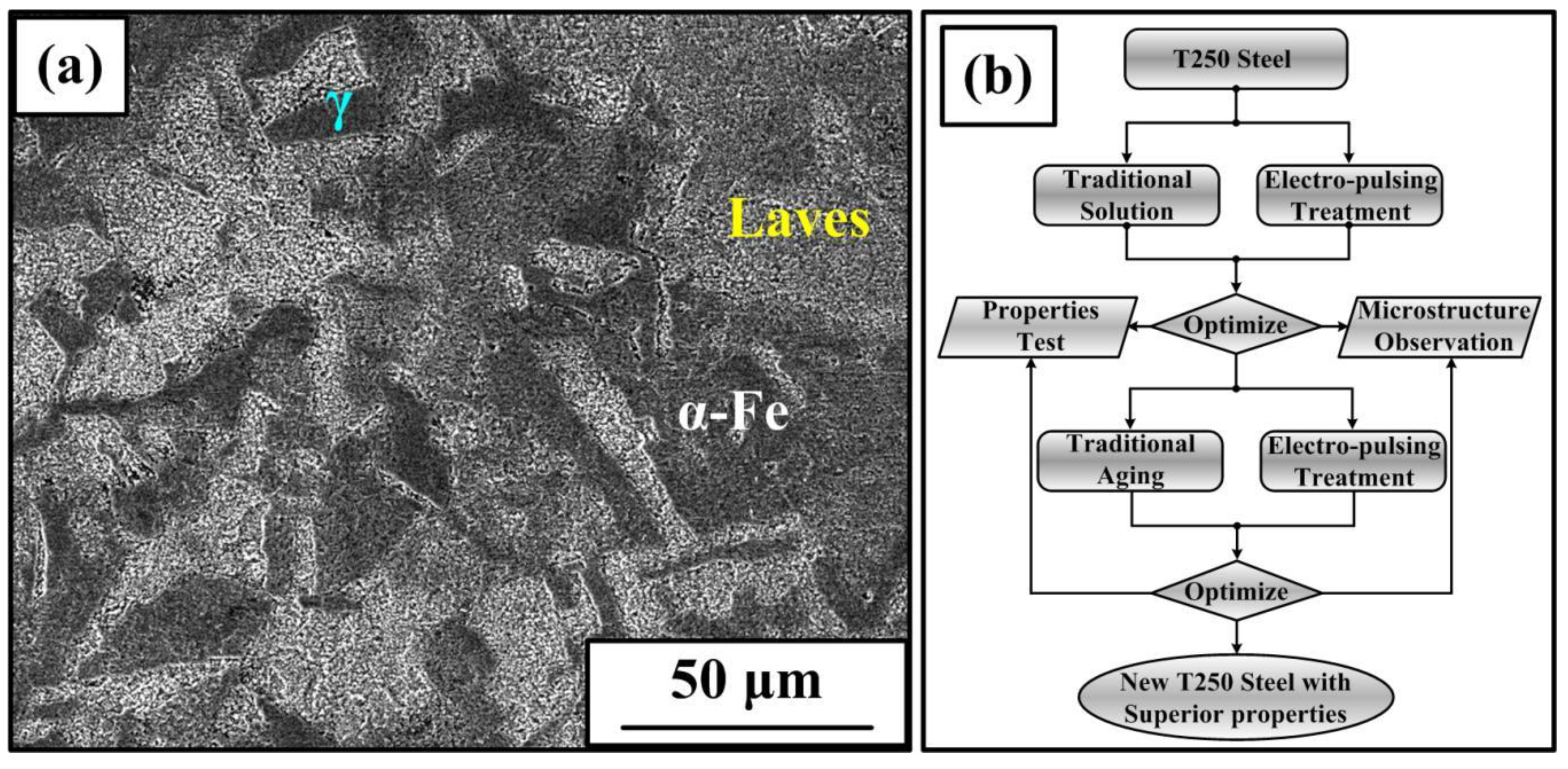
2.1. Materials and Methods

The materials used in this work is commercial T250 steel and the initial state is annealed (Figure 1a, containing ferrite, Laves phase (compounds with Ti, Mo, and Al) and γ phase (FeNi3)), and the chemical composition (weight percentage: wt.%) of the T250 steel is listed in Table 1. The T250 steel was machined into slices (50 × 10 × 2.5 mm3) by CNC wire cutting machine (Jiangsu Dongqing CNC Machine Tool Co., LTD, Taizhou, China). Then, all the Samples will be traditionally and electro-pulsing treated, respectively, and the treating flow is shown in Figure 1b. As is seen, the state of samples for aging treatment is optimized according to the mechanical properties of samples after solution heat treatment. Traditional solution heat treatment (TS) was carried out at 820 °C for 1 h under water-cooling condition. While the corresponding electro-pulsing treatment (EPS) was taken into force via using a self-made machine containing thyristor circuit (Figure 2b) under water-cooling condition.

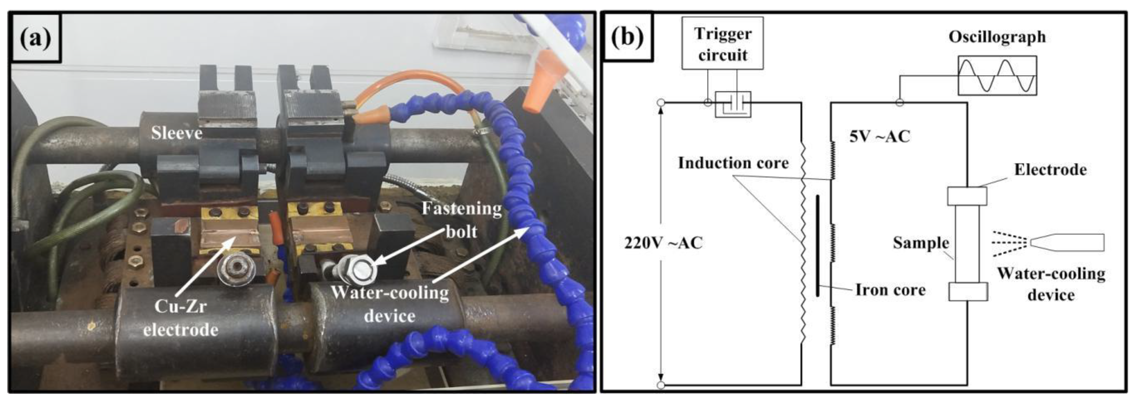
2.2. Technological Parameters and the Electro-Pulsing Apparatus

The electro-pulsing apparatus and thyristor circuit are shown in Figure 2, the samples are fastened on the Cu–Zr electrodes by the fastening bolts, and the distance between the two electrodes can be adjusted by the sleeves. The electro-pulsing parameters were set up by an EPT software, and the detailed parameters (current density and period) are 8.15 × 10⁷ A/m2 and 360 ms, respectively. For aging process, the parameters of traditional treatment (TA) and electro-pulsing treatment (EPA) under air-cooling conditions were 480 °C, 2 h and 3.40 × 10⁸ A/m2, 220 ms and 280 ms, respectively. The temperature during electro-pulsing treatment is measured by an infrared gun (TBSC).

2.3. Microstructural Analysis and Property Measurement

Samples for optical microscopy (OM) was polished and then etched with ethanol +6.25 wt.% iron trichloride +20 vol.% hydrochloric acid solution. The Axio Imager M2M optical microscopy (Carl Zeiss AG, Oberkochen, Germany) was used for grain boundary and microstructure observation. Samples for transmission electron microscopy (TEM) test were polished to about 30 μm thickness and then the twin-jet electro-polishing in a 20 vol.% perchloric ethanol electrolyte at −20 °C under a voltage of 20 V was adopted. The JEM-2100F transmission electron microscopy (JEOL LTD, Tokyo, Japan) is adopted for substructure and precipitation detection. The X-ray diffraction (XRD) was conducted by using a D/Max 2500PC XRD machine (Scanning range was 20°–110° and scanning rate was 2°/min) (Rigaku Coporation, Tokyo, Japan). The tensile test was conducted at room temperature by using a MTS-810 performance testing machine (MTS Industrial System (China) Co., LTD, Shenzhen City, China), and the tensile speed is 0.003 s−1.

3. Results and Discussion

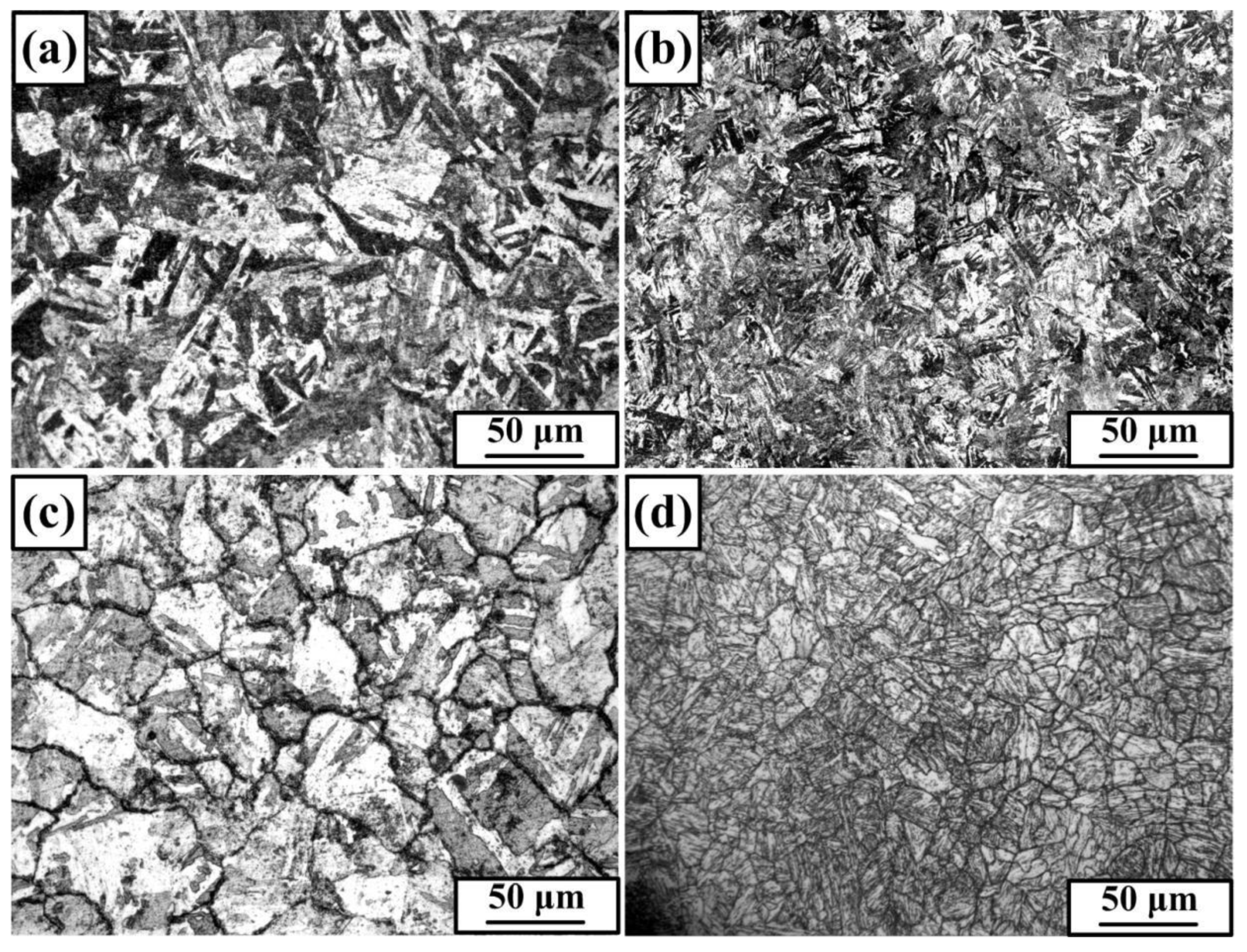
3.1. Optimization of Solid-Solution Treatment

Figure 3 shows the microstructure and prior austenitic grain boundary of samples under different kinds of solution heat treatment. The microstructure of TS sample is composed of lath-like martensite. As for the EPS sample, the corresponding microstructure is also mainly comprised of lath-like martensite (the temperature is measured to be 807 °C, which is above Ac3 temperature of T250 steel [30]). Whereas, the width of martensitic laths in the EPS sample is obviously smaller than that of the TS sample. Besides, the prior austenitic grains of EPS sample are also finer than the TS sample (Figure 3c,d). The above mentioned results indicate that the martensitic laths and prior austenitic grains of T250 steel are refined by electro-pulsing treatment, and the refined martensite is a consequence of the refined prior austenitic grains [31]. This can be attributed to the enhanced nucleation rate of austenitic transformation induced by electro-pulsing current [32]. Furthermore, the growth of austenitic grains are also inhibited due to the extremely short treating procedure of EPS treatment. In this way, finer microstructure can be inevitably obtained by electro-pulsing treatment.
In order to deeply investigate the substructure of martensite in the EPS sample, TEM observation was conducted. As depicted in Figure 4, the width of martensitic laths in the TS sample is larger than the EPS sample (Figure 4a,e), which is consistent with the results of Figure 3. In addition, compared with the TS sample, the EPS presents severer dislocation pile-ups (Figure 4b,f). Furthermore, the results of Figure 4d demonstrate that there also exist some stacking faults in the EPS sample. It is worth noting that some layered retained austenite is also detected in EPS sample (Figure 4a,c), and the crystal orientation between retained austenite and martensite is the K–S relationship [33]: (011)α//(111)γ, [–100]α//[1–10]γ. whereas in the TS sample, almost no retained austenite can be distinguished. To get rid of the scale limitation of TEM observation in the detection of retained austenite in different samples, XRD detection is necessary to be conducted.
The results of the XRD measurement are shown in Figure 5. Characteristic peaks of austenite are found in the XRD patterns of the EPS sample. However, no characteristic peaks of retained austenite can be detected in the TS sample. The XRD results imply that the electro-pulsing treatment promotes the formation of retained austenite. For the formation mechanisms, the homogeneously distributed Ni content in samples at initial state, the crystal defects in austenitic grains and the grain refinement effect after EPS treatment should be taken into consideration. Firstly, because the treating period is extremely short, there’s no sufficient time for Ni content to homogeneously dissolve into the matrix. Because the Ni is an austenitic stabilizing element, the retained austenite is easier to be formed in the Ni enriched area in the EPS sample [34]. Secondly, under the intensely impact of the electron wind, there will exist more crystal defects in austenitic grains during EPS treatment, and as a result, the martensitic transformation will be inhibited [35]. Finally, because the average grain size of the EPS sample (9.7 μm, Figure 3d, calculated by Image Pro Plus 6.0 software) (6.0 version, Media Cybernetics, MD, USA) is remarkably smaller than that of the TS sample (38.2 μm, Figure 3c, calculated by Image Pro Plus 6.0 software), the interface energy of EPS sample between austenite and martensite is higher than the TS sample, thus, the growth of martensitic in the EPS sample will stop earlier than the TS sample when the growth is about to attach the prior austenitic grain boundary. As a result, more retained austenite is formed in the EPS sample [36].
Generally speaking, the stacking faults are hard to form in ferrous materials with bcc structure due to the relatively higher stacking fault energy. As for the formation mechanisms of nano stacking faults in the EPS sample (Figure 4d), the authors believe that the thermal compressive stress induced by electro-pulsing is necessary to be investigated, based on the previous research [29]. During EPS treatment, due to the extremely rapid heating speed, the thermal expansion will be delayed [37], which will result in the generation of thermal compressive stress (FT) in the EPS sample. The value FT of can be estimated by [38]:
F T = E λ Δ T
where λ is the thermal expansion coefficient, ΔT refers to the temperature rise, and E refers to Young’s modulus. Whereas, in fact, there exist a critical force (FC) for the formation of stacking faults, and its value is governed by [39]:
F C = 2 μ α b p D + μ a 2 24 π ω b p
where D means the grain size of EPS sample, bp is the partial dislocation vector, μ refers to shear modulus, a denotes the lattice constant, and ω is the width of nano stacking faults in Figure 4d. If the actually driven force is smaller than this critical force, no stacking faults will be formed. During EPS treatment, the thermal compressive stress can be regarded as the driven force for the formation of stacking faults. According to Equations (1) and (2), the calculated thermal compressive stress is about 1.79 GPa, which is obviously higher than the calculated critical force (0.54 GPa). Therefore, it can be concluded that the formation of nano-stacking faults is attributed to the thermal compressive stress during EPS treatment.
The tensile properties of solution heat treated samples are shown in Figure 6. The yield strength and elongation of TS sample are 794 MPa and 15.8%. For the EPS sample, the corresponding values are 1045 MPa and 19.8%, which are apparently higher than that of the TS sample. The higher tensile properties of the EPS sample are attributed to its refined prior austenitic grains. Based on the Hall–Petch effect, with the decrease of prior austenitic grain size, the yield strength is bound to increase. Furthermore, the deformation process will also become more homogeneous because of the refined prior austenitic grains. Moreover, except for the refined grain size, the stacking faults and retained austenite are also favorable for the better tensile properties. Under the pinning effect of stacking faults on dislocation movement, the strength will be enhanced. As for the effect of retained austenite on mechanical properties of the EPS sample, it can be reflected by the work-hardening rate curves (Θ, (dσtrue/dεtrue)/σtrue, σtrue is true stress and εtrue is true strain). As is depicted in Figure 6b, because of the finer grain size and martensitic laths, the dislocation are easier to be entangled with each other in the EPS sample. Therefore, the initial work-hardening rate of the EPS sample is higher than the TS sample. Moreover, in contrast to the disappeared work-hardening ability in the TS sample at a true strain of 0.038, the EPS sample possesses more significant continuous work-hardening capability (Figure 6b). This can be attributed to the prevention of crack propagation in the EPS sample during tensile deformation, which is better for the improvement of ductility [40]. During this process, when the crack extends to the layered retained austenite, the martensitic transformation will be promoted so that the further plastic deformation will be guaranteed and the work-hardening can be continued [40]. The above-mentioned effect of retained austenite on mechanical properties of the EPS sample is known as the transformation induced plasticity (TRIP) effect.

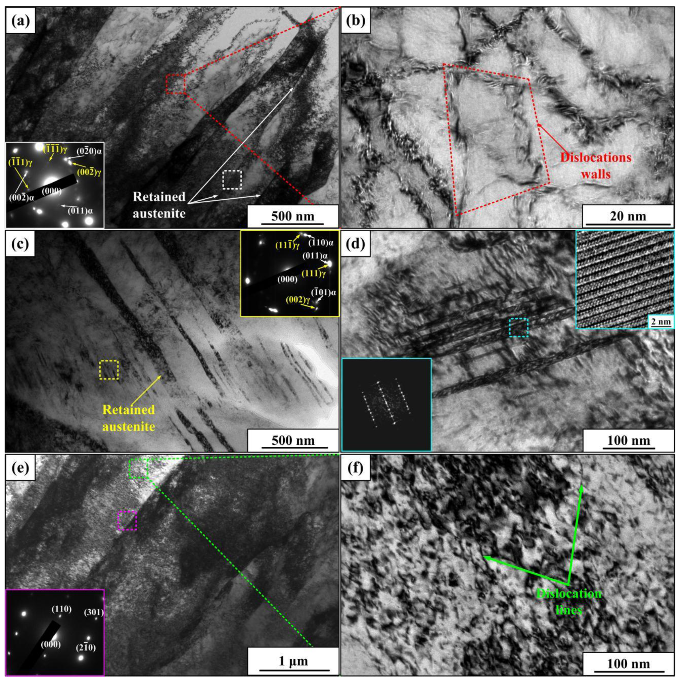
3.2. Optimization of Aging Treatment

In order to develop T250 steel with higher strength and ductility, the EPS sample with better properties is taken as the initial state of the aging treatment, according to the results of Section 3.1. The microstructure of the EPS + EPA samples with different treating period is given in Figure 7. After 220 ms of the EPA treatment, a large number of rod-like η-Ni3Ti precipitates with a length of 32 nm were found. Based on the SAED (Selected Area Electron Diffraction) results (the left insert in Figure 7a), retained austenite is also found in the EPS + EPA (220 ms) sample. In contrast to the EPS sample (Figure 4c), the width of retained austenite in the EPS + EPA (220 ms) sample was smaller. Furthermore, there are almost no characteristic peaks of retained austenite in the corresponding XRD patterns, which indicates the decomposition of retained austenite during 220 ms of the EPA treatment were found. For the EPS + EPA (280 ms) sample, the η-Ni3Ti precipitates are also detected and the average length was about 47 nm. This indicates that with the increase in the EPA treating period, the η-Ni3Ti precipitates present significant growth. Whereas, it is worth noting that some nano-globular phase with a size less than 10 nm are observed in the EPS + EPA (280 ms) sample (Figure 7b–f). The results of SAED patterns presented in Figure 7c,d, and f demonstrate that the globular phase is austenite. Also, it is seen from the results of XRD patterns (Figure 5), characteristic peaks of austenite appear again when the EPA treating time arrives 280 ms. Consequently, the nano austenite in the EPS + EPA (280 ms) sample can be considered as nano-reverted austenite.
The results of Figure 5 have shown that the characteristic peaks of austenite disappeared in the EPS + EPA (220 ms) sample. Whereas, after the EPA treatment for 280 ms, the characteristic peaks of austenite appeared again. This indicates that during EPA treatment for 220 ms, there exists the decomposition of the layered retained austenite in EPS sample. As for the EPA treatment for 280 ms, there also exists the formation of nano-reverted austenite. Even though the crystal structure of retained austenite and reverted austenite are crystallographically identical, it is still necessary to discuss the formation mechanism of nano-reverted austenite because of its totally different morphology and size from the retained austenite. At first, the local enrichment of Ni should be firstly discussed. Compared with the EPS + EPA (220 ms) sample, the η-Ni3Ti precipitates in the EPS + EPA (280 ms) sample show more significant growth. This needs higher local enrichment of Ni in the matrix. Then, because the Ni is austenitic stabilization element, there will be more reverted austenite in the EPS + EPA (280 ms) sample. In other words, the chemical conditions of α’→γ reverse transformation in the EPS + EPA (280 ms) sample are more sufficient than the EPS + EPA (220 ms) sample.
The dislocation morphology, retained austenite and nano stacking faults in the EPS sample are also responsible for the formation of nano-reverted austenite, and the detailed mechanisms are given in Figure 8. As shown in Figure 8a,b, the dimension characteristic of a single dislocation line is anisotropic, and affected by this, the second phase will grow into a rod-like shape [41]. Whereas, the dislocation pile-ups are more isotropic than the dislocation line, the morphology of the second phase will be globular under this condition [41]. Based on the results of Figure 4b,f, the nano-reverted austenite will finally grow into a globular shape. Moreover, considering the reduction in the energy of austenitic reverse transformation, the existence of retained austenite and stacking faults can accelerate the formation of nano-reverted austenite. Owing to the same crystal structure of retained austenite and reverted austenite, the reverted austenite tends to nucleate on the retained austenite. In this regard, the nucleation energy is relatively lower than nucleate in other regions so that the nucleation on retained austenite is easier to occur. This can also be verified by the results of Figure 7c, the distribution of nano-reverted austenite at layered retained austenite is clearly detected. More important, the α’→γ reverse transformation will generally undergo twice-lattice shear [42]. As depicted in Figure 8d, because the nano stacking faults have already possessed the a/6<111> plane, which is the same as the hexagonal closely arranged surface after the first lattice shear, the reverse transformation energy can also be reduced [42]. Thereupon, the existence of stacking faults is also a favorable factor for the formation of nano-reverted austenite. The above mentioned discussion is mainly related the effect of the substructure on the distribution and morphology of nano-reverted austenite. As for the nano size and intensive distribution of reverted austenite, it is related with enhanced nucleation rate [32] and extreme-treating time for growth induced by the EPA treatment.
For the EPS + TA sample, the existence of η-Ni3Ti precipitates with a length of 54 nm is also detected (Figure 9a,b). Because the η-Ni3Ti precipitates have enough time for growth during TA treatment, their size is also larger than that in the EPS + EPA sample. And also, compared with the EPS + EPA sample, the overgrowth of Ni3Ti in the EPS + TA sample will lead to more Ni consumption so that the local enrichment of Ni does not exist in the EPS + TA sample. Consequently, the reverted austenite cannot be detected in EPS + TA sample (Figure 5 and Figure 9a). What’s more, according to Figure 9c,d, some globular Fe2Mo precipitates were also observed. The Fe2Mo precipitate is an overaging product. During the early precipitation stage, the structure of η precipitate is a core-shell structure [43], i.e., the growth of Ni3Ti core of can be restricted by the Ni3Mo shell. Whereas, with the extension of aging time, the shell (Ni3Mo) will be gradually dissolved into the matrix so that the size of the core (Ni3Ti) will become larger (the so called overaging state). Meanwhile, the dissolved Ni3Mo shell will also be transformed into Fe2Mo precipitates [43].
The traditional peak aging regime for maraging steel at TS state is holding at 480 °C for 2–3 h [28]. Whereas, compared with TS sample, the EPS sample possesses higher energy (higher entanglement degree of dislocation and the existence of nano stacking faults) for the following aging process. Therefore, in contrast to traditional peak aging regime, the peak aging time should be less than 2–3 h. Thus, the EPS + TA sample is in the overaging state. Besides, the measured temperature of the EPS + EPA (220 and 280 ms) sample are 295 °C and 393 °C, which are lower than the temperature of the traditional peak aging regime. Based on classical nucleation theory, it seems that the thermal conditions for the formation of η-Ni3Ti precipitates in the EPS + EPA sample are inadequate. Whereas, in fact, the nucleation sites of η-Ni3Ti precipitates must be some crystal defects (such as vacancy or interstitial atom). Thus, due to the higher resistivity of these crystal defects, the temperature around the nucleation sites will be higher than the measured values (295 and 393 °C) in the EPS + EPA sample [44]. In a word, even though the temperature of the whole samples are lower than the temperature of traditional peak aging regime, the temperature of nucleation area of η-Ni3Ti will be even more higher than the samples so that the precipitation of η-Ni3Ti still possesses sufficient thermal conditions. Moreover, due to the extremely short treating period of the EPA treatment, there is no sufficient time for the growth of η-Ni3Ti. Consequently, compared with the EPS + TA sample, the size of η-Ni3Ti precipitate is smaller in the EPS + EPA sample.
The tensile properties of aging treated samples are displayed in Figure 10. The yield strength and elongation of the EPS + TA sample are 1870 MPa and 16.1%. As for the electro-pulsing treated sample, the corresponding values are 1987 MPa, 17.5%, and 2123 MPa, 20.1% for the EPS + EPA (220 ms) and EPS + EPA (280 ms) samples, respectively. These results indicate that under the effect of electro-pulsing, the strength and ductility of aging treated sample are improved simultaneously. Take the precipitation strengthening mechanism into consideration, the contribution of precipitates to the yield strength (Δσp) is governed by [45]:
Δ σ p = 0.4 M G b π 1 υ ln ( 2 r / b ) λ P ,
where, M is the Taylor factor, G is the shear modulus, b means the Burgers vector, ν is Poisson’s ratio, and λp refers to the average spacing of the rod-like precipitates. Because the size of η-Ni3Ti precipitates (r, considered as a sphere, increase with the increment in the length of rod-like precipitate) in the EPS + EPA sample is smaller than that in the EPS + TA sample, therefore, the contribution of precipitates to yield strength in the EPS + EPA sample is higher than the EPS + TA sample. Consequently, the EPS + EPA sample possesses higher yield strength. On the other hand, due to the bigger size of η-Ni3Ti, the lattice mismatch between precipitates and matrix in the EPS + TA sample is higher than that in the EPS + EPA sample, which will lead to crack initiation at the interface of precipitate and matrix [46]. Consequently, the ductility of the EPS + EPA sample is relatively higher. It is worth noting that, the tensile properties of the EPS + EPA (280 ms) sample are also better than that of the EPS + EPA (220 ms) sample. This can be attributed to the existence of nano-reverted austenite in the EPS+EPA (280 ms) sample. Compared with the EPS + EPA (220 ms) sample, despite the relatively bigger size of η-Ni3Ti in the EPS + EPA (280 ms) sample, the nano-reverted austenite is also an effective strengthening phase. Hence, the EPS + EPA (280 ms) sample possesses higher strength. Moreover, the TRIP effect induced by nano-reverted austenite are also helpful for the modification of ductility. Therein, compared with the EPS + EPA (220 ms), the EPS + EPA (280 ms) possesses better ductility.
Figure 9b shows the work-hardening rate curves of aging treated samples. As is seen, due to the relatively bigger size of austenitic grains, the work-hardening rate of EPS + TA sample is the lowest. Besides, the EPS + EPA (280 ms) sample possesses the highest initial work-hardening rate, which is induced by the co-strengthening effect of η-Ni3Ti and nano-reverted austenite. Furthermore, unlike the continuously decreased work-hardening rate of EPS + TA and EPS + EPA (220 ms) samples, and peak is observed in work-hardening rate curve of EPS + EPA (280 ms) sample. This interesting phenomenon is related with the TRIP effect induced by nano-reverted austenite in EPS + EPA (280 ms) sample [36]. During this process, the gradually concentrated local stress around the nano-reverted austenite will lead to the increase in work-hardening rate [40]. Whereas, after the γα’ transformation, the concentrated local stress will be released so that the work-hardening rate will decrease again [40].
Based on the above mentioned results, the optimized electro-pulsing treatment can simultaneously enhance the strength and ductility of T250 steel very efficiently. However, there still exist some deficiencies of this technology. For example, the formation mechanism of retained austenite in EPS is related with the heterogeneously distributed Ni element. Whereas, if this technology is applied in the microstructure refinement of materials at semi-solid state or as cast state, there may exist elemental segregation, which is harmful to the mechanical properties. Besides, the grain refinement effect is sensitive to the electro-pulsing parameters. If the parameters are not appropriate, there will be no refinement effect or the grains will be coarser. So, the authors will continue to study the detailed effect of electro-pulsing current on the structure-property relationship of metallic materials so that the application of electro-pulsing technology will be more universal and more advanced.

4. Conclusions

In summary, high-energy electro-pulsing current is applied in cobalt-free maraging steel to obtain more advanced mechanical properties. Compared with TS treatment, after EPS treatment within only 360 ms, substantial retained austenite and nano-stacking faults are formed. Moreover, finer prior austenitic grains and martensitic lath are also acquired. Based on this, the following EPA treatment can promote the formation of finer η-Ni3Ti precipitates and a large amount of nano-reverted austenite within only 280 ms. Under the same initial state, the tensile strength and elongation are both modified via electro-pulsing treatment. Eventually, the best tensile properties are optimized to be 2123 MPa (Yield strength) and 20.1% (Total elongation, TE%) by EPS + EPA (280 ms) treatment. To summarize, the electro-pulsing treatment can be a novel and effective method to developing new cobalt-free maraging steel with superior properties.

Author Contributions

Conceptualization, D.P.; methodology, Y.Z. and X.X.; formal analysis, Y.W., and Y.Z.; investigation, D.P. and Y.W.; data curation, D.P. and X.C.; writing—original draft preparation, D.P.; writing—review and editing, Y.W. and X.C.; visualization, Y.W. and X.X.; supervision, Y.Z.; project administration, X.X. and Y.Z.

Funding

This research was supported by the National Natural Science Foundation of China (Grant No. 51701080) and Talent Development Program-Outstanding Youth Fund of Jilin Province (Grant No. 20190103053JH).

Acknowledgments

TEM observation by Yitong Wang is sincerely acknowledged.

Conflicts of Interest

The authors declare no conflict of interest.

References

  1. Guo, Z.; Sha, W.; Vaumousse, D. Microstructural evolution in a PH 13–8 stainless steel after aging. Acta Mater. 2003, 51, 101–116. [Google Scholar] [CrossRef]
  2. Luo, H.; Shi, J.; Wang, C.; Gao, W.; Sun, X.; Dong, H. Experimental and numerical analysis on formation of stable austenite during the intercritical annealing of 5Mn steel. Acta Mater. 2011, 59, 4002–4014. [Google Scholar] [CrossRef]
  3. Liu, H.W.; Liu, J.W.; Luo, C.P.; Liu, Z.J. Microstructure, crystallography of phase transformation and multiple precipitations in PH 15-7 Mo stainless steel. J. Alloys Compd. 2016, 672, 386–392. [Google Scholar] [CrossRef]
  4. Xu, W.; Rivera-Díaz-del-Castillo, P.E.J.; Yan, W.; Yang, K.; San Martín, D.; Kestens, L.A.I.; van der Zwaag, S. A new ultra-high strength stainless steel strengthened by various coexisting nanoprecipitates. Acta Mater. 2010, 58, 4067–4075. [Google Scholar] [CrossRef]
  5. Rajkumar, K.V.; Rao, B.P.C.; Sasi, B.; Kumar, A.; Jayakumar, T.; Raj, B.; Ray, K.K. Characterization of aging behaviour in M250 grade maraging steel using eddy current non-destructive methodology. Mater. Sci. Eng. A 2007, 464, 233–240. [Google Scholar] [CrossRef]
  6. Tharian, K.T.; Sivakumar, D.; Ganesa, R.; Balakrishnan, P.; Sinha, P.P. Development of new low nickel, cobalt free maraging steel. Mater. Sci. Technol. 1991, 7, 1082–1088. [Google Scholar] [CrossRef]
  7. Li, K.; Wei, L.; An, B.; Yu, B.; Misra, R.D.K. Aging phenomenon in low lattice-misfit cobalt-free maraging steel: Microstructural evolution and strengthening behavior. Mater. Sci. Eng. A 2019, 739, 445–454. [Google Scholar] [CrossRef]
  8. Squire, R.; Wilson, E.A. Effect of cobalt on impact toughness of steels. Mater. Sci. Technol. 1994, 10, 52–55. [Google Scholar] [CrossRef]
  9. Li, Y.C.; Yan, W.; Cotton, J.D.; Ryan, G.J.; Shen, Y.F.; Wang, W.; Shan, Y.Y.; Yang, K. A new 1.9 GPa maraging stainless steel strengthened by multiple precipitating species. Mater. Des. 2015, 82, 56–63. [Google Scholar] [CrossRef]
  10. Shekhter, A.; Aaronson, H.; Miller, M.; Ringer, S.; Pereloma, E. Effect of aging and deformation on the microstructure and properties of Fe-Ni-Ti maraging steel. Metall. Mater. Trans. A 2004, 35, 973–983. [Google Scholar]
  11. Wang, C.C.; Zhang, C.; Yang, Z.G. Austenite layer and precipitation in high Co-Ni maraging steel. Micron 2014, 67, 112–116. [Google Scholar] [CrossRef] [PubMed]
  12. Masoumi, M.; de Barrous, I.F.; Herculano, L.F.G.; Coelho, H.L.F.; de Abreu, H.F.G. Effect of microstructure and crystallographic texture on charpy impact test for maraging 300 steel. Mater. Charact. 2016, 120, 203–209. [Google Scholar] [CrossRef]
  13. Du, P.J.; Yang, D.P.; Bai, M.K.; Xiong, X.C.; Wu, D.; Wang, G.D.; Yi, H.L. Austenite stabilisation by two step partitioning of manganese and carbon in a Mn-TRIP steel. Mater. Sci. Technol. 2019, 17, 2084–2091. [Google Scholar] [CrossRef]
  14. Harding, I.; Mouton, I.; Gault, B.; Raabe, D.; Kumar, K.S. Carbon partitioning and microstructure evolotion during tempering of an Fe-Ni-C steel. Scripta Mater. 2019, 172, 38–42. [Google Scholar] [CrossRef]
  15. Pereloma, E.; Shekhter, A.; Miller, M.; Ringer, S. Aging behaviour of an Fe-20Ni-1.8Mn-1.6Ti-0.59Al (wt.%) maraging alloy: Clustering, precipitation and hardening. Acta Mater. 2004, 52, 5589–5602. [Google Scholar] [CrossRef]
  16. Li, K.; Yu, B.; Misra, R.D.K.; Han, G.; Liu, S.; Shang, C.J. Strengthening of cobalt-free 19Ni3Mo1.5Ti maraging steel through high-density and low lattice-misfit nanoscale precipitates. Mater. Sci. Eng. A 2018, 715, 174–185. [Google Scholar] [CrossRef]
  17. Jiang, S.H.; Wang, H.; Wu, Y.; Liu, X.J.; Chen, H.H.; Yao, M.J.; Gault, B.; Ponge, D.; Raabe, D.; Hirata, A.; et al. Ultrastrong steel via minimal misfit and high-density nanoprecipitation. Nature 2017, 544, 460–465. [Google Scholar] [CrossRef]
  18. Yang, M.X.; Yang, G.; Liu, Z.D.; Wang, C.; Huang, C.X. Significant enhancement of strength in a lamellar-type nanostructured maraging steel subjected to equal-channel angular pressing for 12 passes. Mater. Sci. Eng. A 2012, 550, 429–433. [Google Scholar] [CrossRef]
  19. Yang, M.X.; Yang, G.; Liu, Z.D.; Wang, C.; Hu, C.; Huang, C.X. Effect of equal-channel angular pressing on the microstructures and properties of 18Ni(C250) maraging steel. Acta Metall. Sin. 2012, 48, 164–169. [Google Scholar] [CrossRef]
  20. Zhang, W.; Zou, D.N.; Qiao, G.J. Hot deformation behavior and microstructural evolution of as-cast co containing maraging stainless steel. Mater. Res. Express 2019, 6, 086586. [Google Scholar] [CrossRef]
  21. Mizubayashi, H.; Okuda, S. Structural relaxation induced by passing electric current in amorphous Cu50Ti50 at low temperature. Phys. Rev. B 1989, 40, 8057–8060. [Google Scholar] [CrossRef] [PubMed]
  22. Song, H.; Wang, Z.J.; He, X.D.; Duan, J. Self-healing of damage inside metal triggered by electropulsing stimuli. Sci. Rep. 2017, 7, 7097. [Google Scholar] [CrossRef] [PubMed]
  23. Zhao, Y.G.; Zhang, J.T.; Tan, J.; Ma, B.D. Microstructure refinement and property improvement of metastable austenitic manganese steel induced by electro-pulsing. J. Iron Steel Res. Int. 2014, 21, 685–689. [Google Scholar] [CrossRef]
  24. Zhou, Y.; Chen, G.Q.; Fu, X.S.; Zhou, W.L. Effect of electropulsing on deformation behavior of Ti-6Al-4V alloy during cold drawing. Trans. Nonferrous Met. Soc. China 2014, 24, 1012–1021. [Google Scholar] [CrossRef]
  25. Zhang, X.; Li, H.W.; Zhan, M. Mechanism for macro and micro behaviors of the Ni-based superalloy during electrically-assisted tension: Local Joule of heating effect. J. Alloys Compd. 2018, 742, 480–489. [Google Scholar] [CrossRef]
  26. Zhao, Y.G.; Ma, B.D.; Guo, H.C.; Ma, J.; Yang, Q.; Song, J.S. Electropulsing strengthened 2GPa boron steel with good ductility. Mater. Des. 2013, 43, 195–199. [Google Scholar] [CrossRef]
  27. Ma, B.D.; Zhao, Y.G.; Bai, H.; Ma, J.; Zhang, J.T.; Xu, X.F. Gradient distribution of mechanical properties in the high carbon steel induced by the detour effect of the pulse current. Mater. Des. 2013, 49, 168–172. [Google Scholar] [CrossRef]
  28. Pan, D.; Zhao, Y.G.; Xu, X.F.; Wang, Y.T.; Jiang, W.Q.; Chong, X.Y. A novel strengthening and toughening strategy for T250 maraging steel: Cluster-orientation governed higher strength-ductility combination induced by electropulsing. Mater. Des. 2019, 169, 107686. [Google Scholar] [CrossRef]
  29. Pan, D.; Zhao, Y.G.; Wang, Y.T.; Xu, X.F.; Yin, P.L.; Chong, X.Y. Formation of ultrafine pearlites in tempered 42CrMo steel induced by electro-pulsing. Mater. Lett. 2019, 251, 73–77. [Google Scholar] [CrossRef]
  30. Gui, B.C.; Yang, Z.Y.; Jiang, Y.H.; Ding, Y.L. Effect of solution temperature on mechanical properties of corrosion-resistant maraging steel. J. Iron Steel Res. 2012, 24, 45–48. [Google Scholar]
  31. Loewy, S.; Rheingans, B.; Meka, S.R.; Mittemeijer, E.J. Modulated martensite formation behavior in Fe-Ni-based alloys; athermal and thermally activated mechanisms. J. Mater. Res. 2015, 30, 2101–2107. [Google Scholar] [CrossRef]
  32. Pan, D.; Wang, Y.T.; Zhao, Y.G.; Xu, X.F.; Chong, X.Y.; Yin, P.L. Completely wetted α/α grain boundaries in electro-pulsing treated DP600 steel under different cooling conditions. Mater. Lett. 2019, 252, 264–267. [Google Scholar] [CrossRef]
  33. Zhang, M.X.; Kelly, P.M. Accurate orientation relationship between ferrite and austenite in low carbon martensite and granular bainite. Scripta Mater. 2002, 47, 749–755. [Google Scholar] [CrossRef]
  34. Wang, Y.T.; Pan, D.; Zhao, Y.G.; Sun, L.Y.; Xu, X.F.; Yin, P.L.; Chong, X.Y.; Jiang, W.Q.; Wang, Z. Enhanced stability of retained austenites in quenched 25SiMn2MoV steel by electro-pulsing current. Mater. Sci. Eng. A 2019, in press. [Google Scholar] [CrossRef]
  35. Strife, J.R.; Carr, M.J.; Ansell, G.S. The effect of austenite prestrain above the Md temperature on the martensitic transformation in Fe-Ni-Cr-C alloys. Metall. Trans. A 1977, 8, 1471–1484. [Google Scholar] [CrossRef]
  36. Yang, H.S.; Bhadeshia, H.K.D.H. Austenite grain size and the martensite-start temperature. Scr. Mater. 2009, 60, 493–495. [Google Scholar] [CrossRef]
  37. Zhang, W.; Sui, M.L.; Zhou, Y.Z.; He, G.H.; Guo, J.D.; Li, D.X. Electro-pulsing induced evolution of microstructures in materials. Acta Metall. Sin. 2003, 39, 1009–1018. [Google Scholar]
  38. Tang, D.W.; Zhou, B.L.; Gao, H.; He, G.H. Thermal stress relaxation behavior in thin films under transient laser-pulse heating. J. Appl. Phys. 1993, 73, 3749–3752. [Google Scholar] [CrossRef]
  39. Huang, C.X.; Wang, K.; Wu, S.D.; Zhang, Z.F.; Li, G.Y.; Li, S.X. Deformation twinning in polycrystalline copper at room temperature and low strain rate. Acta Mater. 2006, 54, 655–665. [Google Scholar] [CrossRef]
  40. Pan, D.; Zhao, Y.G.; Xu, X.F.; Wang, Y.T.; Jiang, W.Q.; Ju, H. Effect of high-energy and instantaneous electropulsing treatment on microstructure and properties of 42CrMo steel. Acta Metall. Sin. 2018, 54, 1245–1252. [Google Scholar]
  41. Wang, Y.T.; Zhao, Y.G.; Xu, X.F.; Pan, D.; Jiang, W.Q.; Yang, X.H.; Wang, Z. Superior mechanical properties induced by the interaction between dislocations and precipitates in the electro-pulsing treated Al-Mg-Si alloys. Mater. Sci. Eng. A 2018, 735, 154–161. [Google Scholar] [CrossRef]
  42. Zhu, J.; Zhao, Y.W.; Pan, T.X.; Cai, Q.G. Investigation on reverse austenite in 18Ni(250 grade) maraging steel. Iron Steel 1981, 16, 41–45. [Google Scholar]
  43. Tian, J.L.; Li, Y.C.; Wang, W.; Yan, W.; Shan, Y.T.; Jiang, Z.H.; Yang, K. Alloying element segregation effect in a multi-phase strengthened maraging stainless steel. Acta Metall. Sin. 2016, 52, 1517–1526. [Google Scholar]
  44. Zhang, X.; Li, H.W.; Zhan, M.; Shao, G.D.; Ma, P.Y. Extraordinary effect of the δ phase on the electrically-assisted deformation responses of a Ni-based superalloy. Mater. Charact. 2018, 144, 597–604. [Google Scholar] [CrossRef]
  45. Srivatsan, T.S. Dispersion strengthened aluminum alloys. Mater. Manuf. Process. 1991, 6, 565–568. [Google Scholar] [CrossRef]
  46. Ashby, M.F. Work hardening of dispersion-hardened crystals. Philos. Mag. 1966, 14, 1157–1178. [Google Scholar] [CrossRef]
Figure 1. The microstructure of T250 steel at annealed state (a) and the Schematic diagram showing the treating flow of this work (b).
Metals 09 01299 g001
Figure 2. The physical map of the electro-pulsing apparatus (a) and the sketch map of the thyristor circuit (b).
Metals 09 01299 g002
Figure 3. Optical microscopy (OM) images showing the microstructure of the traditional solution heat treatment (TS) sample (a), the electro-pulsing treatment (EPS) sample (b), the prior austenitic grain boundary of the TS sample (c), and the EPS sample (d).
Metals 09 01299 g003
Figure 4. Transmission electron microscopy (TEM) images showing the martensitic laths (a), dislocations in martensitic laths (b), retained austenite (c), nano stacking faults (d) in the EPS sample and the martensitic laths (e), dislocations in martensitic laths (f) in the TS sample; the insert maps show the patterns or HRTEM image of the selected area in the corresponding figures.
Metals 09 01299 g004
Figure 5. X-ray diffraction (XRD) patterns of samples under different kinds of treatment.
Metals 09 01299 g005
Figure 6. Tensile properties of samples under different kinds of solid-solution treatment: (a) engineering tensile curves, (b) normalized work-hardening rate curves.
Metals 09 01299 g006
Figure 7. TEM images of EPS + EPA (220 ms) sample (a) and EPS + EPA (280 ms) (bf); The insert maps show the SAED patterns of the selected area in the corresponding figures; The (f) is the dark field image of (e); REA—retained austenite, RTA—reverted austenite.
Metals 09 01299 g007
Figure 8. Sketch maps showing the effects of dislocation morphology (a,b), retained austenite (c) and nano stacking faults (d) on the formation of nano-reverted austenite.
Metals 09 01299 g008
Figure 9. TEM images of precipitates (a), dark field image of Ni3Ti (b), dark field image of Fe2Mo (c) and HRTEM image of precipitates (d) in EPS + TA sample. The insert maps show the SAED or FFT patterns of the selected area in the corresponding figures.
Metals 09 01299 g009
Figure 10. Tensile properties of samples under different kinds of aging treatment: (a) Engineering tensile curves, (b) Normalized work-hardening rate curves.
Metals 09 01299 g010
Table 1. The nominal composition of commercial T250 steel (wt.%).
ElementNiCrMoTiAlSiMnFe
wt.%18.860.373.061.200.110.010.01Bal.
Note: The content of C, Co, S, and P are all less than 0.003%, the content of O and N in the molten steel are less than 20 ppm.

