Design of ESR Slag for Remelting 9CrMoCoB Steel under Simple Protective Ar Gas


Abstract
:
1. Introduction
2. Experiments and Calculations
2.1. Determining the Basic Slag
2.2. Factsage Calculations and the Equilibrium Reaction Experiments
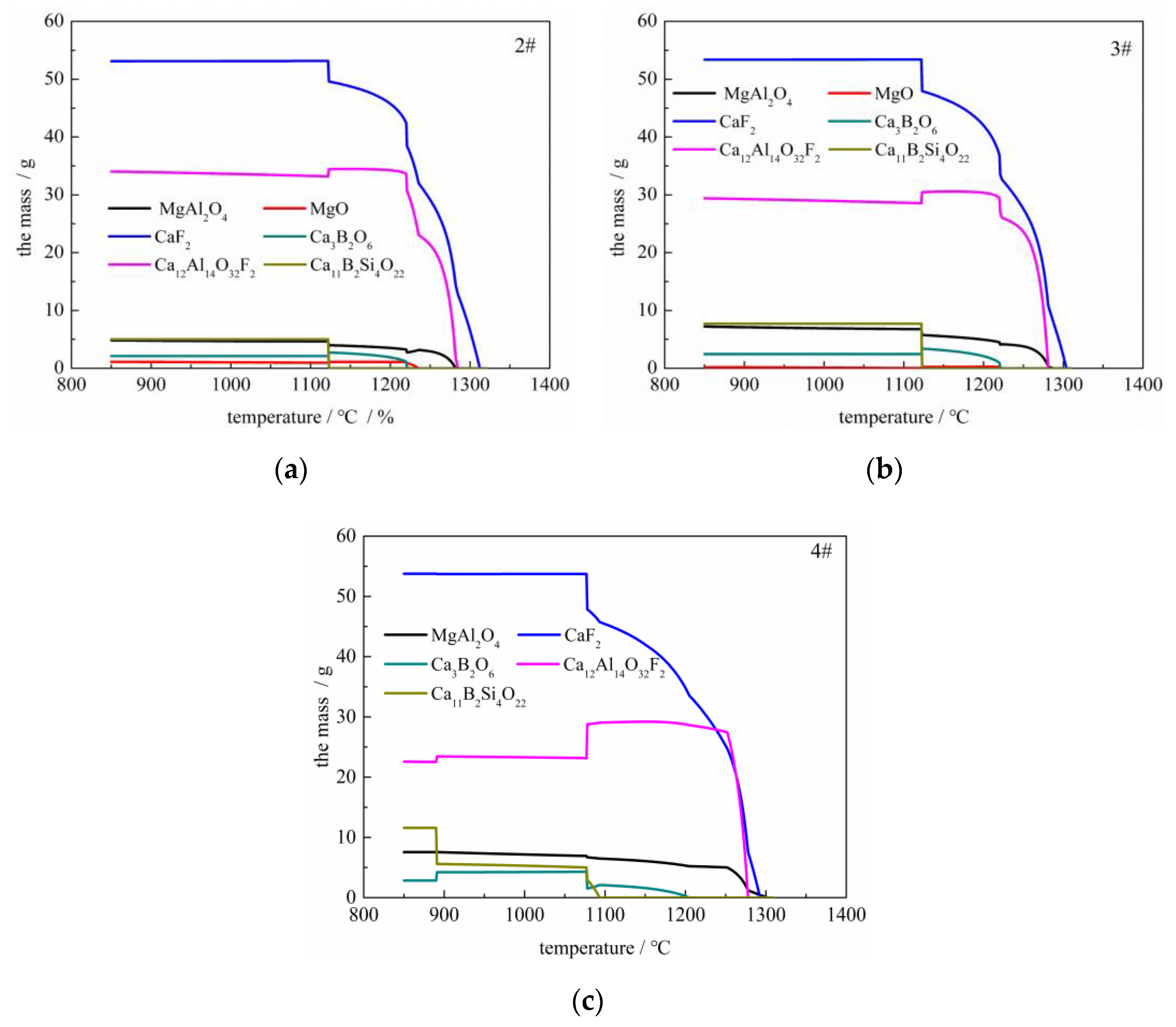
2.2.1. Factsage Calculation
2.2.2. Equilibrium Reaction Experiments
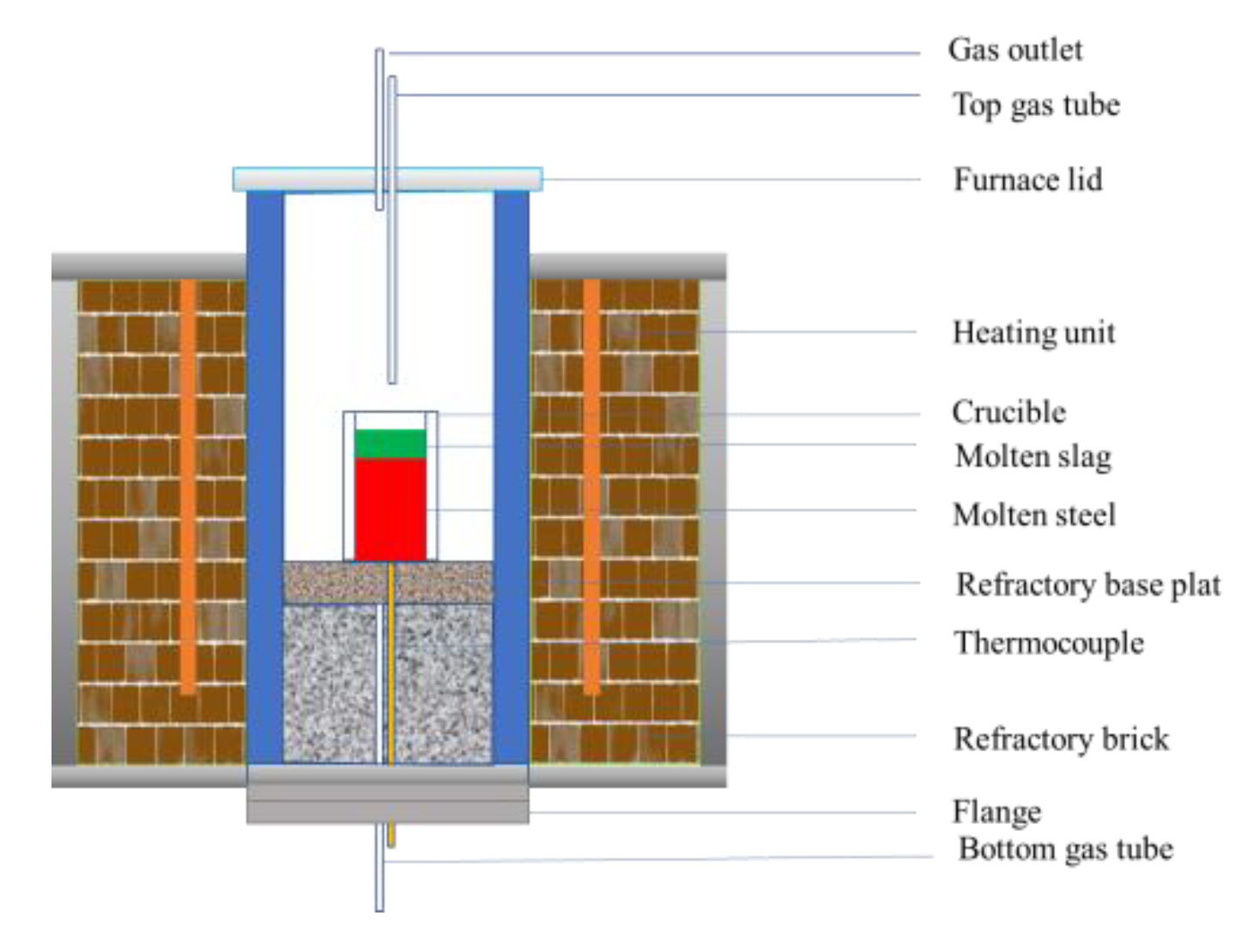
2.3. Laboratory-Scale ESR Experiments
2.3.1. The Viscosity of the Proper Slags
2.3.2. Laboratory-Scale Simple Protective Gas ESR Experiments
2.4. Analysis
3. Results and Discussions
3.1. Calculated Results by Using Factsage 7.3
3.2. Results of Equilibrium Reaction Experiments
3.3. The Viscosity of the Proper Slags
3.4. Laboratory-Scale ESR Experiments
4. Conclusions
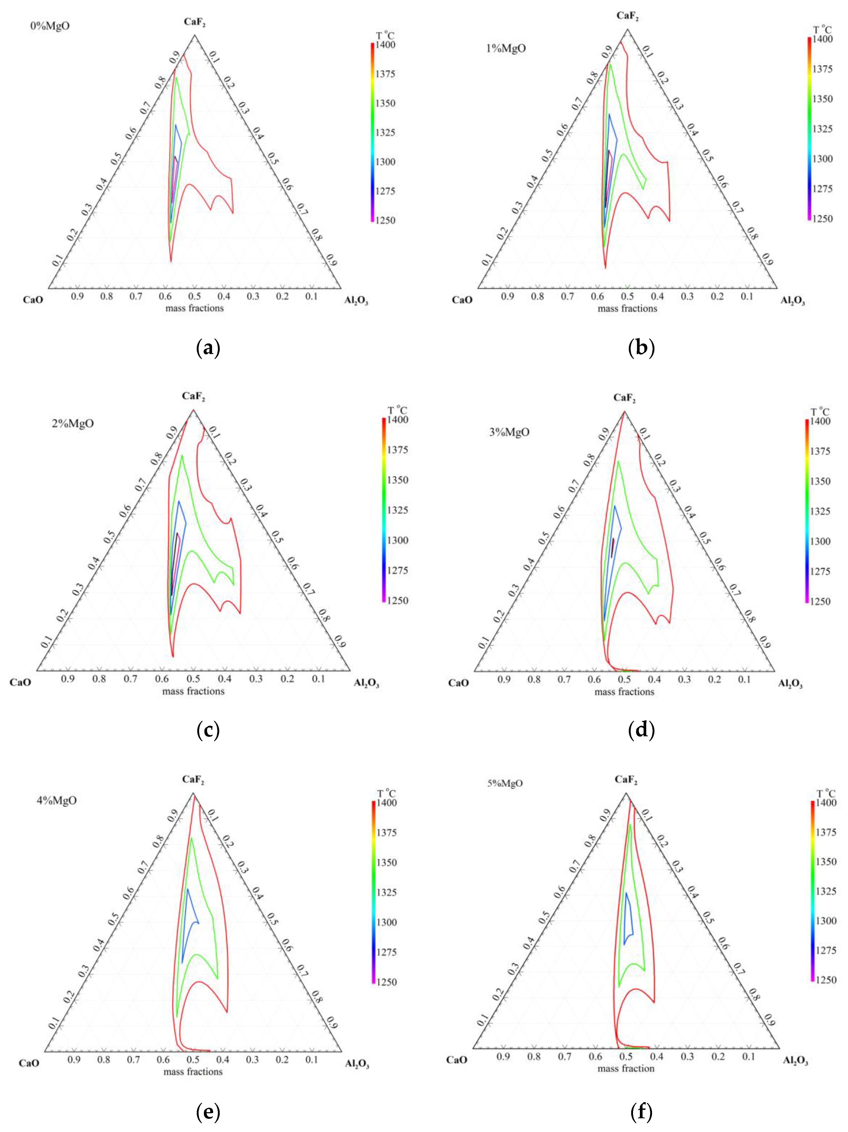
- (1)
- The liquid phase region of CaF2–CaO–Al2O3–x%MgO (0≤ x ≤5) at 1300~1400 °C with the MgO addition, increased first, then, decreased.
- (2)
- With the increasing B2O3 content, the equilibrium boron content increased, whereas the equilibrium Si, Al contents decreased simultaneously, and, at a given B2O3 addition, the equilibrium B, Al contents decreased, whereas the equilibrium Si content increased concurrently with increasing SiO2 content.
- (3)
- On the whole, the Factsage calculation results were similar to the experimental results under the same experimental conditions.
- (4)
- The designed slags of 55%CaF2–20%CaO–22%Al2O3–3%MgO–0%SiO2–0.5%B2O3 and 55%CaF2–20%CaO–22%Al2O3–3%MgO–1%SiO2–1%B2O3 were not suitable for remelting qualified 9CrMoCoB ingot for the obvious loss and macro-segregation of Si.
- (5)
- The slags of 55%CaF2–20%CaO–22%Al2O3–3%MgO–2%SiO2–1.3%B2O3 and 55%CaF2–20%CaO–22%Al2O3–3%MgO–3%SiO2–1.7%B2O3 were appropriate for ESR remelting qualified 9CrMoCoB ingot under the simple protective Ar gas (volume fraction of O2 was around 0.5%) with controlling the B, Si, and Al contents within the target range and avoiding the macrosegregation of Si.
Author Contributions
Funding
Conflicts of Interest
References
- Viswanatha, R.; Coleman, K.; Rao, U. Materials for ultra-supercritical coal-fired power plant boilers. Int. J. Pres. Ves. Pip. 2006, 11, 778–783. [Google Scholar] [CrossRef]
- Viswanathan, R.; Henry, J.F.; Tanzosh, J.; Stanko, G.; Shingledecker, J.; Vitalis, B.; Purgert, R. US program on materials technology for ultra-supercritical coal power plants. J. Mater. Eng. Perform. 2005, 3, 281–292. [Google Scholar] [CrossRef]
- Blaes, N.; Donth, B.; Bokelmann, D. High chromium steel forgings for steam turbines at elevated temperatures. Energy Mater. 2007, 4, 207–213. [Google Scholar] [CrossRef]
- Masuyama, F. History of power plants and progress in heat resistant steels. ISIJ Int. 2001, 6, 612–625. [Google Scholar] [CrossRef]
- Zeiler, G.; Bauer, R.; Putschoegl, A. Experiences in manufacturing of forgings for power generation application. Metall. Ital. 2010, 6, 33–40. [Google Scholar]
- Blaes, N.; Donth, B.; Diwo, A.; Bokelmann, D. Rotor Forgings for Steam Turbines with High Efficiency. In Advances in Materials Technology for Fossil Power Plants, Proceedings of the 7th International Conference, Geauga, OH, USA, 28 September–1 October 2014; Gandy, D., Shingledecker, J., Gandy, D., Shingledecker, J., Eds.; ASM International: Geauga, OH, USA, 2014; pp. 448–458. ISBN 13 9781627080606. [Google Scholar]
- Kim, D.S.; Lee, G.J.; Lee, M.B.; Hur, J.I.; Lee, J.W. Manufacturing of 9CrMoCoB Steel of Large Ingot with Homogeneity by ESR Process. In IOP Conference Series: Materials Science and Engineering; IOP Publishing: Bristol, UK, 2016; Volume 143, p. 012002. [Google Scholar]
- Minh, N.Q.; King, T.B. The contribution of electrochemical reactions to sulfur transfer from electrode to slag in electroslag remelting. Metall. Trans. B 1979, 10, 623–629. [Google Scholar] [CrossRef]
- Li, S.J.; Cheng, G.G.; Yang, L.; Chen, L.; Yan, Q.Z.; Li, C.W. A Thermodynamic model to design the equilibrium slag compositions during electroslag remelting process: Description and verification. ISIJ Int. 2017, 57, 713–722. [Google Scholar] [CrossRef]
- Pateisky, G.; Biele, H.; Fleischer, H.J. The Reactions of Titanium and Silicon with Al2O3-CaO-CaF2 Slags in the ESR Process. J. Vac. Sci. Technol. 1972, 9, 1318–1321. [Google Scholar] [CrossRef]
- Medina, S.F.; Cores, A. Thermodynamic aspects in the manufacturing of microalloyed steels by the electroslag remelting process. ISIJ Int. 1993, 33, 1244–1251. [Google Scholar] [CrossRef]
- Reyes-Carmona, F.; Mitchell, A. Deoxidation of ESR slags. ISIJ Int. 1992, 32, 529–537. [Google Scholar] [CrossRef]
- Mitchell, A. The chemistry of ESR slags. Can. Metall. Q. 1981, 20, 101–112. [Google Scholar] [CrossRef]
- Mohanasundaram, M.; Roy, G.G.; Prakash, S. Thermodynamic Modelling for Design of Synthetic Slag for Inclusion Remova. Trans. Indian Inst. Met. 2019, 72, 1111–1118. [Google Scholar] [CrossRef]
- Ren, Y.; Zhang, Y.; Zhang, L. A kinetic model for Ca treatment of Al-killed steels using FactSage macro processing. Ironmak. Steelmak. 2017, 44, 497–504. [Google Scholar] [CrossRef]
- Ai, X.B.; Bai, H.; Zhao, L.H.; Cang, D.Q.; Tang, Q. Thermodynamic analysis and formula optimization of steel slag-based ceramic materials by FACTsage software. Int. J. Miner. Metall. Mater. 2013, 20, 379–385. [Google Scholar] [CrossRef]
- Presoly, P.; Korp, J.; Schneider, R. Electrical conductivity and corresponding specific energy consumption of new MgO-containing ESR-slags. Arch. Metall. Mater. 2008, 53, 567–574. [Google Scholar]
- Dong, Y.W.; Jiang, Z.H.; Cao, Y.L.; Zhang, H.K.; Shen, H.J. Effect of MgO and SiO2 on surface tension of fluoride containing slag. J. Cent. South Univ. 2014, 21, 4104–4108. [Google Scholar] [CrossRef]
- Duan, S.C.; Shi, X.; Mao, M.T.; Yang, W.S.; Han, S.W.; Guo, H.J.; Guo, J. Investigation of the Oxidation Behaviour of Ti and Al in Inconel 718 Superalloy During Electroslag Remelting. Sci. Rep. 2018, 8, 5232. [Google Scholar] [CrossRef]
- Zhengbang, L. A New Advance Electroslag Metallurgy in the 21th Century. Special Steel 2004, 25, 1–5. [Google Scholar]
- Arh, B.; Podgornik, B.; Burja, J. Electroslag remelting: A process overview. Mater. Technol. 2016, 50, 971–979. [Google Scholar] [CrossRef]
- Wright, S.; Zhang, L.; Sun, S.; Jahanshahi, S. Viscosity of a CaO-MgO-Al2O3-SiO2 melt containing spinel particles at 1646K. Metall. Mater. Trans. B 2000, 31, 97–104. [Google Scholar] [CrossRef]
- Roscoe, R. The viscosity of suspensions of rigid spheres. Br. J. Appl. Phys. 1952, 3, 267–269. [Google Scholar] [CrossRef]
- Wright, S.; Zhang, L.; Sun, S.; Jahanshahi, S. Viscosity of calcium ferrite slags and calcium alumino-silicate slags containing spinel particles. J. Non-Cryst. Solids 2001, 282, 15–23. [Google Scholar] [CrossRef]


| Content | C | Si | Mn | B | Al | Cr | Mo | Co | O | Ni | Nb | N | Fe |
|---|---|---|---|---|---|---|---|---|---|---|---|---|---|
| EXP. | 0.136 | 0.0495 | 0.34 | 0.010 | 0.003 | 9.36 | 1.48 | 1.28 | 0.0028 | 0.16 | 0.06 | 0.021 | Bal. |
| Min. | 0.110 | - | 0.28 | 0.008 | - | 9.05 | 1.40 | 1.15 | - | 0.10 | 0.04 | 0.015 | |
| Max. | 0.150 | 0.1000 | 0.42 | 0.011 | 0.01 | 9.60 | 1.60 | 1.45 | 0.0035 | 0.25 | 0.07 | 0.030 | |
| Goal | 0.120 | 0.0500 | 0.35 | 0.010 | 0.007 | 9.30 | 1.50 | 1.30 | - | 0.15 | 0.06 | 0.020 |
| C | Si | Mn | B | Al | Cr | Mo | Co | O | Ni | Nb | N | Fe |
|---|---|---|---|---|---|---|---|---|---|---|---|---|
| 0.132 | 0.048 | 0.348 | 0.0098 | 0.004 | 9.49 | 1.54 | 1.27 | 0.0028 | 0.15 | 0.058 | 0.024 | Bal. |
| ESR Melting | Furnace | Simple Protective Furnace |
|---|---|---|
| Remelting speed/kg/min | 1.2 | |
| Mould | Diameter/mm | 125 |
| Electrode | Diameter/mm | 75 |
| Slag | Weight/kg | 3.2 |
| Before Pre-Melted | After Pre-Melted | |||||||||||
|---|---|---|---|---|---|---|---|---|---|---|---|---|
| NO. | CaF2 | CaO | Al2O3 | MgO | SiO2 | B2O3 | CaF2 | CaO | Al2O3 | MgO | SiO2 | B2O3 |
| 1# | 55 | 20 | 22 | 3.0 | 0.0 | 0.5 | 52.90 | 21.15 | 21.71 | 3.08 | 0.18 | 0.47 |
| 2# | 55 | 20 | 22 | 3.0 | 1.0 | 1.0 | 52.60 | 20.56 | 21.46 | 3.03 | 1.16 | 0.96 |
| 3# | 55 | 20 | 22 | 3.0 | 2.0 | 1.3 | 51.96 | 20.22 | 21.19 | 2.98 | 2.11 | 1.24 |
| 4# | 55 | 20 | 22 | 3.0 | 3.0 | 1.7 | 51.32 | 20.03 | 20.91 | 2.95 | 3.05 | 1.61 |
© 2019 by the authors. Licensee MDPI, Basel, Switzerland. This article is an open access article distributed under the terms and conditions of the Creative Commons Attribution (CC BY) license (http://creativecommons.org/licenses/by/4.0/).
Share and Cite
Peng, L.; Jiang, Z.; Geng, X. Design of ESR Slag for Remelting 9CrMoCoB Steel under Simple Protective Ar Gas. Metals 2019, 9, 1300. https://doi.org/10.3390/met9121300
Peng L, Jiang Z, Geng X. Design of ESR Slag for Remelting 9CrMoCoB Steel under Simple Protective Ar Gas. Metals. 2019; 9(12):1300. https://doi.org/10.3390/met9121300
Chicago/Turabian StylePeng, Leizhen, Zhouhua Jiang, and Xin Geng. 2019. "Design of ESR Slag for Remelting 9CrMoCoB Steel under Simple Protective Ar Gas" Metals 9, no. 12: 1300. https://doi.org/10.3390/met9121300
APA StylePeng, L., Jiang, Z., & Geng, X. (2019). Design of ESR Slag for Remelting 9CrMoCoB Steel under Simple Protective Ar Gas. Metals, 9(12), 1300. https://doi.org/10.3390/met9121300