Article

Changes of Microstructures and Mechanical Properties in Commercially Pure Titanium after Different Cycles of Proposed Multi-Directional Forging

1
College of Mechanical Engineering, Guangxi University, No. 100 Daxue Dong Road, Nanning 530004, China
2
College of Mechanical Engineering, Beibu Gulf University, No. 12 Binhai Avenue, Qinzhou 535011, China
*
Author to whom correspondence should be addressed.
Metals 2019, 9(2), 175; https://doi.org/10.3390/met9020175
Submission received: 14 January 2019 / Revised: 27 January 2019 / Accepted: 30 January 2019 / Published: 2 February 2019

Abstract

:
A newly proposed multi-directional forging (MDF) was successfully applied to a commercially pure titanium (CP Ti). Severe plastic deformation would result in significant and complex changes of microstructure and mechanical properties, so microstructure characterization and a mechanical test of CP Ti were conducted after different cycles of MDF. The results demonstrated that dynamic recrystallization was the dominant grain refinement mechanism of MDF CP Ti. With increasing the cycles of MDF, grain size, fraction of low angle grain boundaries and dislocations density decreased due to grain refined. After three cycles of MDF, the mean grain size was about 200 nm. The values of tensile strength and hardness increased significantly from zero cycles to one cycle of MDF, but increased slowly after one MDF cycle. Numerous dimples and tear ridges were present, but the dimples were smaller and shallower with increasing cycles of MDF.

1. Introduction

It was well documented that the final mechanical properties were strongly influenced by several characteristics of microstructure like grain size, phase morphology, residual stress, and so on [1,2]. In the severe plastic deformation (SPD) process, plastic deformation and strain-path resulted in significant and complex changes of microstructure and mechanical properties [3]. In order to control the microstructure and improve its mechanical properties, it was of great significance to study the variation of mechanical properties and microstructure evolution during SPD.
Multi-directional forging (MDF) was a versatile technique of SPD, because it could be relatively easy to produce large bulk samples and the process was readily amenable to simplification [4]. Under the severe plastic deformation due to MDF, grains of bulk metal were significantly refined, and its mechanical properties were also remarkably improved. This received considerable attention on many MDF bulk metals, such as AZ31B magnesium alloy [5], AZ61 Mg alloy [6], Mg-Gd-Y-Ag-Zr alloy [7], Mg-Zn-Zr alloy [8], Al-Cu-Mg alloy [9], and so on.
Most of the above MDF metals had a hexagonal close-packed (HCP) lattice with limited slip systems, which made it difficult to plastically deform at low temperature [10]. Of course, MDF was also applied to fabricate ultra-fine grained commercially pure titanium (UFG CP Ti). This was because UFG CP Ti was an excellent candidate for applications in various areas of mechanical engineering, due to its high corrosion resistance, and in bioengineering due to its complete biocompatibility [11].
MDF could achieve exceptional grain refinement, significantly improving the strength of CP Ti, but only by the use of an industrial air pneumatic hammer. Wang [12] used MDF to process ultrafine-grained CP Ti, after which its mechanical responses and microstructure characters were investigated by a tensile test machine, transmission electron microscopy (TEM) and finally electron back scattered diffraction (EBSD). Xu [13] compared differences of microstructures and mechanical properties between the forging and rolling processes for CP Ti. Mironov [14] studied the evolution of misorientation distribution during warm MDF of CP Ti. In the above literatures on MDF CP Ti, text evolution were laid enough insight by EBSD. However, many surface cracks appeared upon the MDF CP Ti, and variations of mechanical properties and microstructures were not explored after the implementation of different cycles of MDF. As is well known, studies about changes of microstructure and mechanical properties were essential in understanding the mechanisms of plastic deformation and grain refinement [15].
The objective of the present work was to evaluate any changes of microstructures and mechanical properties in CP Ti after any different cycles of proposed MDF. The proposed MDF was based on the conventional MDF, and the MDF sample was machined to the cuboid after each cycle, which could effectively avoid surface cracks. Secondly, the evolution of microstructure was observed by OM and TEM, such that raw grain size and shape were documented by OM, but UFG size and dislocations density were characterized by TEM. Lastly, any variation of mechanical properties was evaluated by a tensile test machine, a microhardness test machine and fractographs of a scanning electron microscope (SEM), respectively.

2. Materials and Methods

2.1. Sample Preparation

The material was a commercially pure Ti with a chemical composition of 0.15 Fe, 0.14 O, 0.008 H, 0.02 N, 0.06 C, and balance Ti in wt.% (Grade 1), which was received as a hot-rolled bar with a mean grain size of 35 μm, as showed in Figure 1. Prior to forging, samples were machined into the cylindrical shape of size Φ35 mm × 60 mm.

2.2. The Proposed Multi-Directional Forging

Based on conventional MDF, the direction of forging was changed by 90° pass-by-pass (i.e., Z to Y to X to Z…). A forging cycle was composed of 3 passes, and 3 cycles were adopted in this study. In the first cycle, the cylindrical samples were heated to 500 °C in an electric resistance furnace and kept for 15 min. After that, the MDF was carried out in air, using an industrial air pneumatic hammer machine (Anyang Forging Press Machinery Industry Co., Ltd., Anyang, China) with a load gravity of 65 kg. The first pass was processed at about 50% reductions along the Z-axis direction. The deformed samples were quenched in water quickly after each pass, then these quenched samples were placed into the electric resistance furnace (Shanghai Jvjing Precision Instrument Manufacturing Co., Ltd., Shanghai, China) again and kept at 500 °C for 5 min. The next pass was along the Y- and X-axis directions respectively, and each pass repeated the above processing, from heating to forging and quenching. When a cycle came to an end, the, quenched sample was machined to the shape of a cuboid by wire-cut electro discharge machining (WEDM), and the four longest edges of the cuboid were filleted by a radius of 5 mm. Finally, the second and the third cycle repeated the processing of the first cycle.

2.3. Microstructural Characterization

For OM, Axio Scope A1 (Carl Zeiss Microscopy GmbH, Jena, Germany) was used. OM observations were performed on a plane of the specimen parallel to the final forging axis. After mechanical polishing, samples were etched for seven seconds using a solution of 2.5 mL HF, 3 mL HNO3, 5 mL HCl and 91 mL H2O. For the transmission electron microscope (TEM), JEM-2100 (JEOL Ltd., Tokyo, Japan) was adopted, and operated at a voltage of 200 kV. After hand-grinding, samples were reduced to a thickness of about 0.10 mm, then the foils were perforated upon the samples by electropolishing in solution of 10 mL HClO4, 90 mL CH3(CH2)3OH and 150 mL CH3OH. For fractographic analysis, a HITACHI SU8020 scanning electron microscope (Hitachi, Ltd., Tokyo, Japan) was selected. The samples were cut from the fracture locations using WEDM and cleaned using a solution of Nital 2% plus a tensoactive agent for a few seconds, followed by ultrasonic cleaning with acetone.

2.4. Mechanical Characterization

The hardness was measured in the cross-sectional samples by using a JXHVST-1000Z microhardness tester (ShangHai MicroCre Light-Mach Tech CO., Ltd., Shanghai, China) with a load of 9.8 N and loading time of 10 s. The reported hardness value was the average of 256 readings, as shown as Figure 2. For a tensile test, the flat specimens were with the gauge dimensions of 1 mm × 10 mm and length 35 mm. Tensile tests were conducted at room temperature using an AGS-J Materials testing machine (Shimadzu, Ltd., Kyoto, Japan) with a constant rate of 1 mm/min. A minimum of three well reproducible tests were performed on each type of specimen.

3. Results

3.1. Morphology Evolution of Deformed Specimens

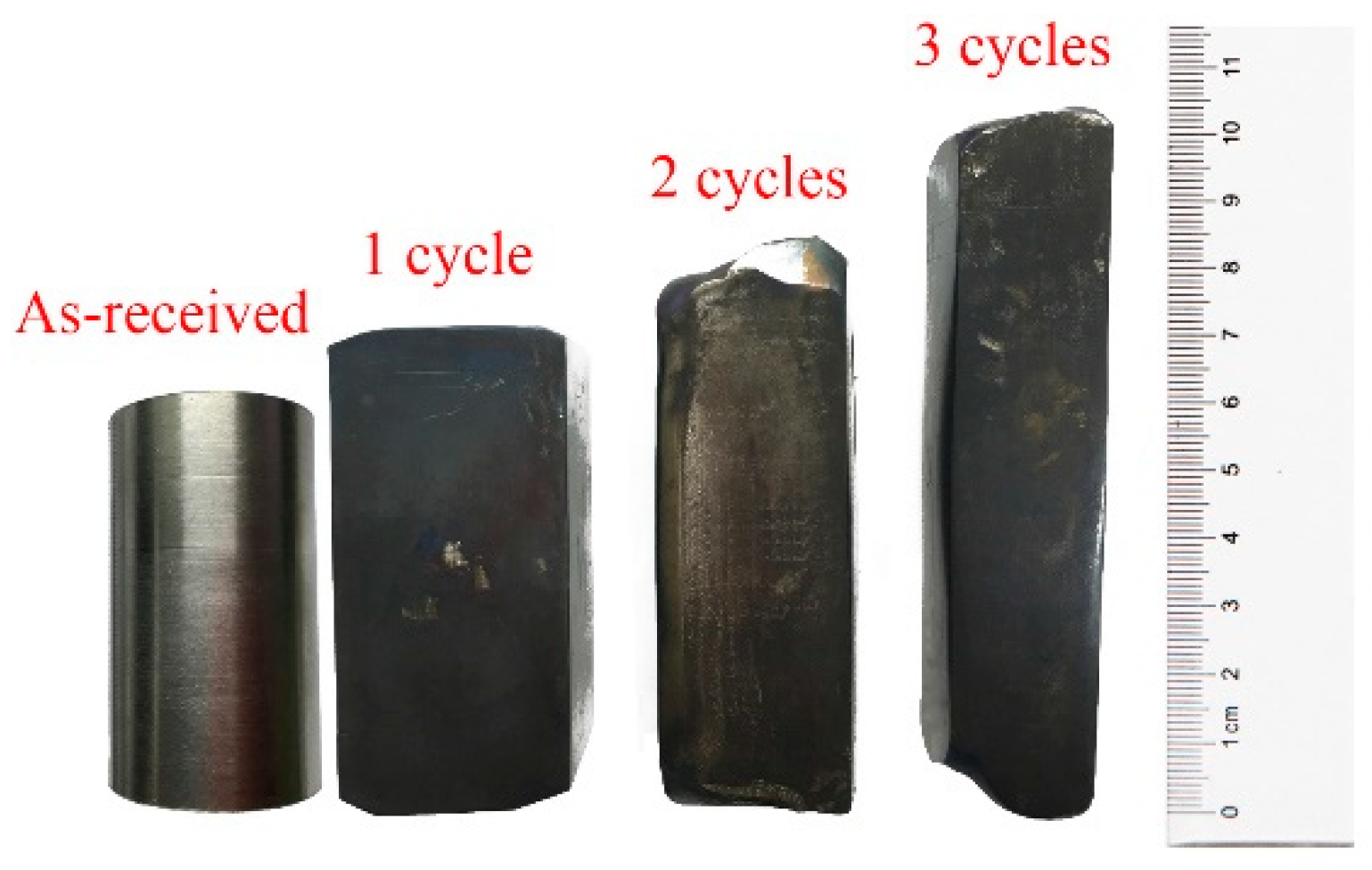
From Figure 3, the received cylindrical samples were forged to the cuboid shape, and were free from surface cracks. These demonstrated that the proposed MDF processing was successful.

3.2. Optical

Optical micrographs of specimens with different cycles of MDF were shown in Figure 1 and Figure 4. The microstructures of the as-received CP Ti were polygonal grains with clear grain boundaries (GBs) and some deformation twins, with the mean grain size about 35 μm, as shown in Figure 1. Severe plastic deformation led to more dislocation accumulations and the production of finer subgrain structures [16,17]. After the first cycle of MDF, polygonal grains were disappeared for refinement, and GBs were ambiguous. With the increase of MDF cycles, the grains were finer.

3.3. TEM

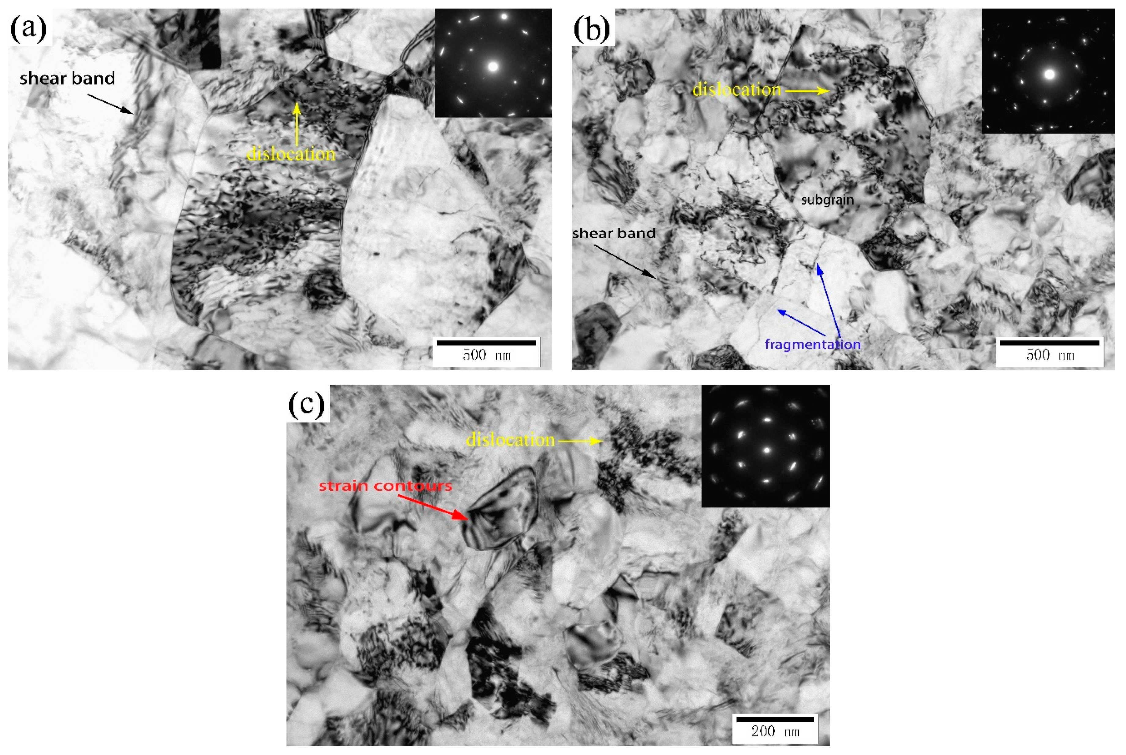
To further investigate the evolution of grain size and dislocation accumulation, TEM was used to observe the microstructures of CP Ti after the different cycles of MDF by the bright field pattern combined with selected area electron diffraction (SAED), as shown in Figure 5.
With an increase in the cycles of MDF, fine equiaxed grains and dislocation densities were well-defined in these typical TEM images. A large amount of dislocations, shear bands and subgrains as such, could be observed, and strain contours which were visible as dark bands within some grains were also found, indicating the existence of residual stresses after MDF. These strain contours were caused by diffraction contrast as the lattice planes gradually changed orientation [18]. From Figure 5a, a large number of dislocations became tangled, piled up and were changed into subgrains, and the mean size of all grains was about 1 μm after one cycle of MDF. Belyakov et al. [19] explained that the mechanism of UFG evolution during MDF was similar to continuous dynamic recrystallization. Additionally, from Figure 5a, GBs were clearly identified, and two of them, a typical incidental dislocation boundary (IDB), and a geometrically necessary boundary (GNB), were widely distributed in some grains with high dislocation densities. The IDBs were low angle grain boundaries (LAGBs) of subgrain cells, which were hypothesized to be the results of dislocations pinning [20]. The GNBs related to the evolution of slip systems between adjacent grains during severe plastic deformation. The typical polycrystalline SAED pattern in Figure 5a (the top right hand side inset within Figure 5) exhibited a more or less continuous diffused ring-like pattern corresponding to LAGBs, with a high density of dislocations, residual stresses and subgrain configurations. From Figure 5b, the subgrains with dense dislocation walls became equiaxed, with the mean grain size being about 500 nm. After two cycles of MDF, the shear band was still the main deformed mechanism, but its width was smaller than after the first cycle of MDF. In addition, many dislocations piled up along the band structures, and these structures developed into subgrains with the increase in the number of MDF cycles. At the same time, grains fragmentation (marked in Figure 5b by the blue arrows) was also found in some grains as a result of deformation twinning [21,22]. The SAED pattern in Figure 5b was close to a series of concentric rings with less elongated diffraction spots, indicating that the fraction of high angle grain boundaries (HAGBs) increased, whereas the fraction of LAGBs and the residual stresses decreased.
After three cycles of MDF, the mean grain size was about 200 nm, its dislocation density was low due to grain hardly refined again, and the GBs were ambiguous as showed in Figure 5c. Of more interest was that twins were not directly found in MDF CP Ti, which were different to ECAPed CP Ti in some literatures [23,24]. The SAED pattern showed diffraction spots arranged in circles, attesting to the large fraction of HAGBs. Some diffraction spots were split, which could be caused by the existence of LAGBs. Elongation of diffraction spots indicated the existence of high residual stresses [25].

3.4. Hardness

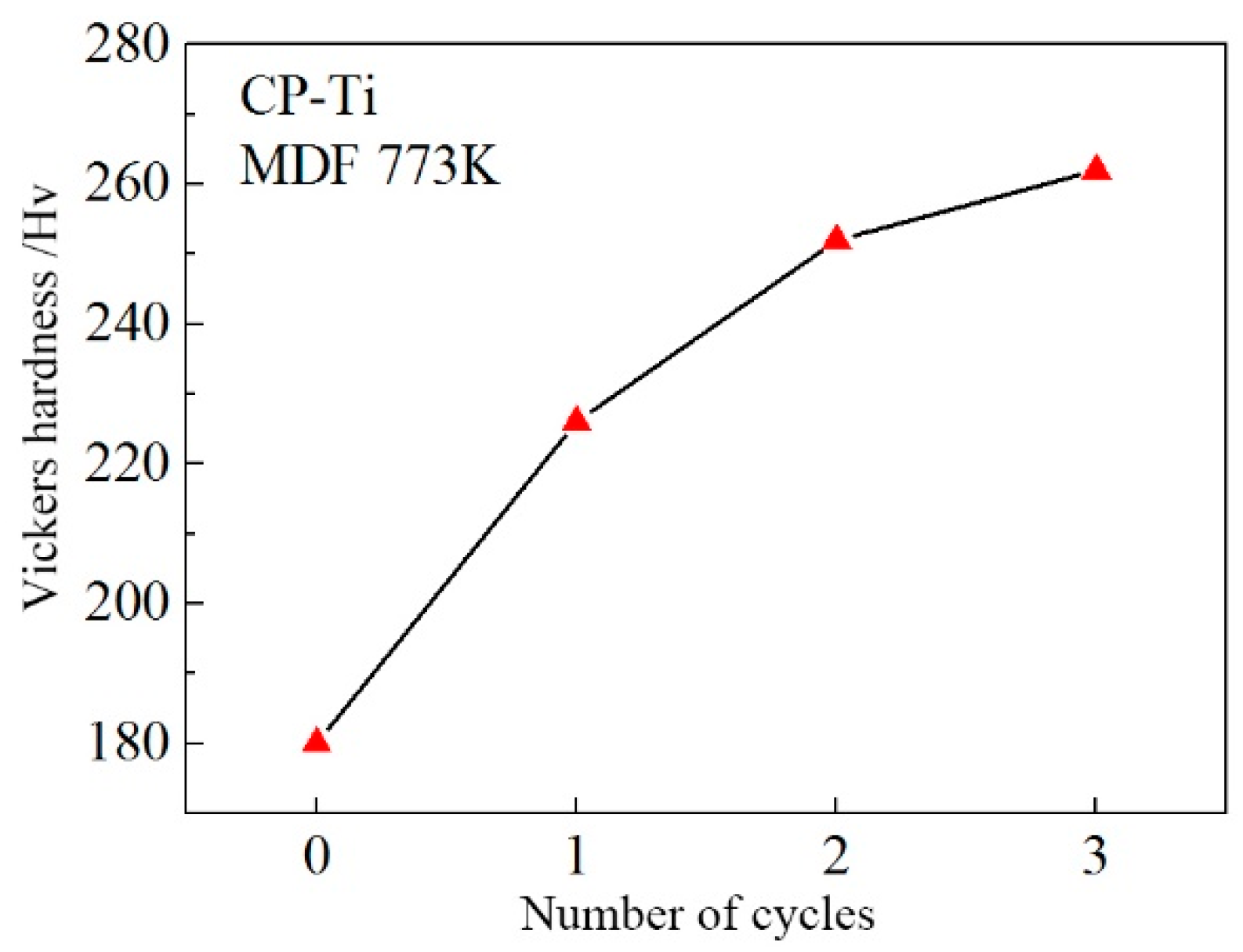
Vickers microhardnesses on the cross-sectional planes were taken along 16 horizontal traverses separated by spacing of 1.0 mm as shown in Figure 2. After averaging the individual measurements of microhardness, the results were shown as Figure 6.
Figure 6 presented the variation of microhardness with the cycles of MDF. It was noticed that the microhardness increased significantly from zero cycles to one cycle of MDF, but increased slowly after one cycle of MDF. The average microhardness of as-received CP Ti was 180.50 Hv, but the average microhardness was 225.36 Hv at the first cycle of MDF. In other words, the hardness increased by a factor of 1.25. However, the hardness value of the second cycle was 249.30 Hv by the increase of only 1.1 factor, and the hardness of the third cycle was 263.65 Hv by the increase of 1.05 factor in comparison to the first cycle. It was similar to many literatures [26,27], which were attributed to the refined grains.

3.5. Tensile Tests

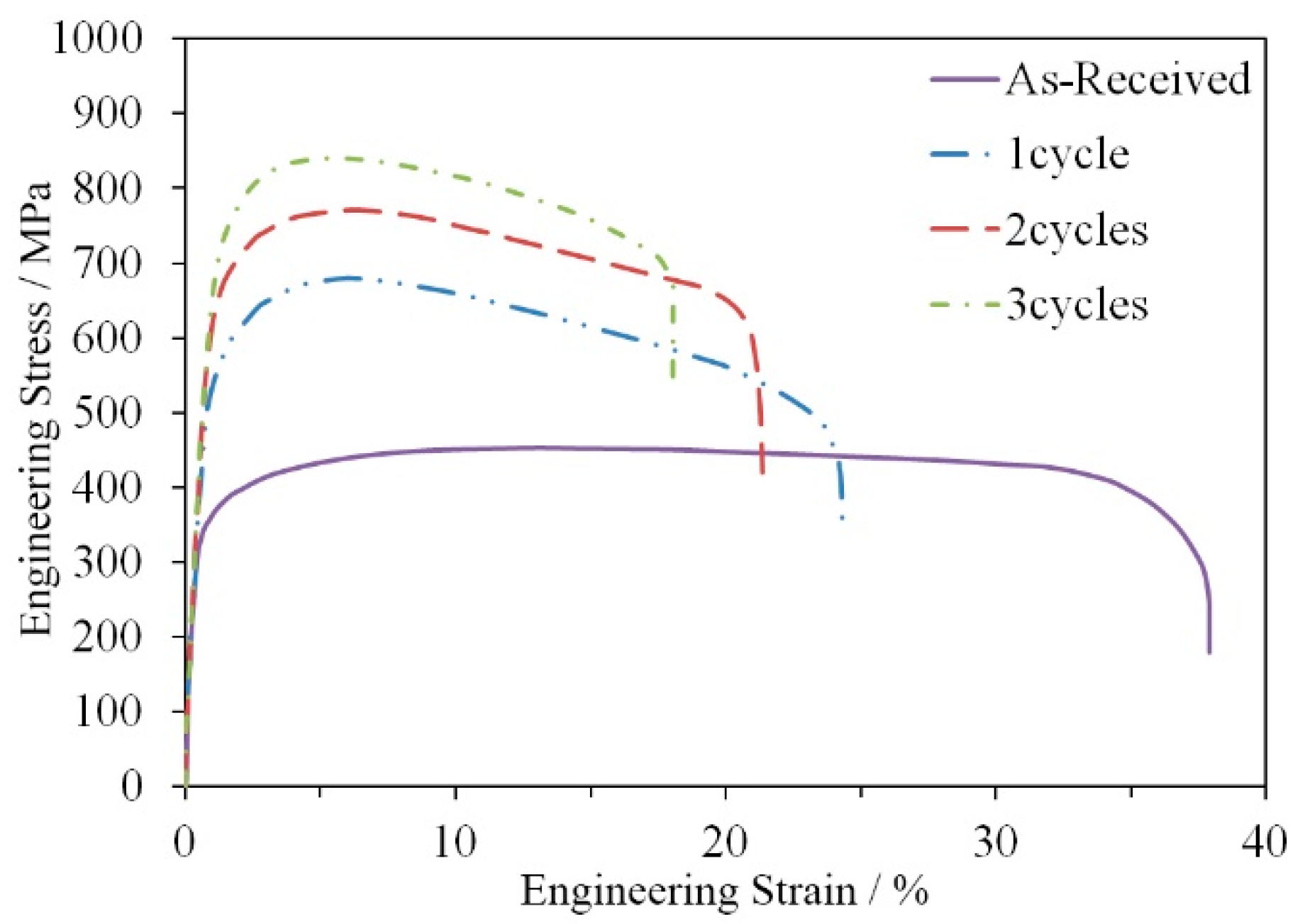
In order to study the tensile performances of UFG materials at room temperature, the engineering stress-strain curves of CP Ti severely deformed by MDF for all cycles were shown in Figure 7.
It was found that the strength significantly increased but ductility decreased. This change was obvious from zero cycles to one cycle of MDF, and then the changing trend was slow. Without yield point, yield stress (YS) was determined according to 0.2% criteria deformation. The YS and the ultimate tensile stress (UTS) are depicted in Figure 8.
It is notable that the largest UTS (830 MPa) of MDF CP Ti was achieved for the samples deformed after three cycles, while the ductility was recorded with the total elongation rate of 17%. For the as-received CP Ti with ductility of 38%, YS was 270 Mpa and UTS was 453 Mpa. At the first cycle of MDF, YS (525 Mpa) and UTS (680 Mpa) increased quickly, with about one time in comparison to those of the as-received CP Ti, while the ductility (24.8%) decreased with 34.7%. At the second cycle of MDF, YS (619 Mpa) and UTS (762 Mpa) increased with 17%, while the ductility (24.8%) decreased with 28.5% than at the first cycle of MDF. At the third cycle of MDF, YS (700 Mpa) and UTS (830 Mpa) slowly increased with 13%, while the ductility (17%) decreased with 31.4% than at the second cycle of MDF. The high strength of CP Ti samples after MDF can be explained mainly in terms of the fine structure and the high dislocation density [28].

4. Discussion

4.1. Effect of Microstructural Evolution on the Mechanical Properties

From the experimental results shown in Figure 6 and Figure 8, it could be found that the hardness, yield and ultimate strength increased instantly after one cycle, but gradually increased with the increasing number of cycles. Corresponding to the above phenomenon, microstructural evolution also showed that grains were significantly refined after one cycle, but they were hard refined with a number of cycles in Figure 4 and Figure 5. The evolution of the mechanical properties in MDF Ti with characteristic grain sizes was consistent with a Hall–Petch relationship.
With respect to the Hall–Petch relationship, many scholars thought that the mechanical properties improvement of UFG materials was in agreement with the linear relation between the rate of increase of the dislocation density, and the inverse of the grain size [29,30,31]. From the typical TEM images shown in Figure 5, there were a large amount of dislocations tangled and piled up and subgrains, etc. Additionally, grain boundaries also effected the mechanical properties of metals. In Figure 5, GBs were clearly identified and two of them, a typical incidental dislocation boundary (IDB), and a geometrically necessary boundary (GNB), were widely distributed in some grains with high dislocation densities. The GNBs related to an evolution of slip systems between adjacent grains during severe plastic deformation. At the same time, the SAED pattern inserted into Figure 5 was exhibited from the more or less continuous diffused ring-like pattern to continuous diffused ring pattern, which meant the large fraction of HAGBs.
The progressive increase of HAGBs during MDF was a typical feature of continuous dynamic recrystallization [32]. Therefore, dynamic recrystallization was the dominant grain refinement mechanism of MDF CP Ti in this study.

4.2. Effect of Microstructural Evolution on the Tensile Facture Toughnesss

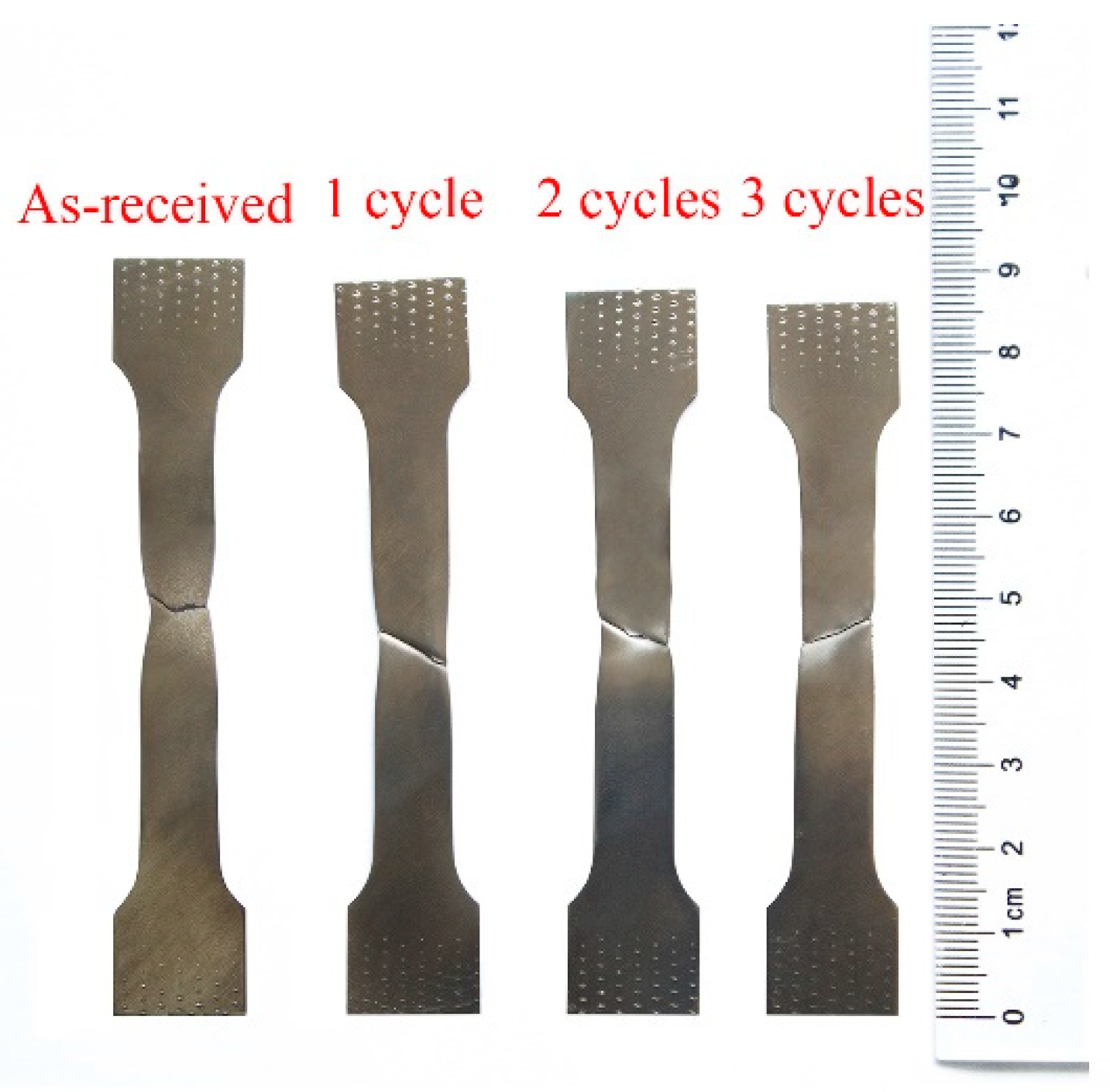
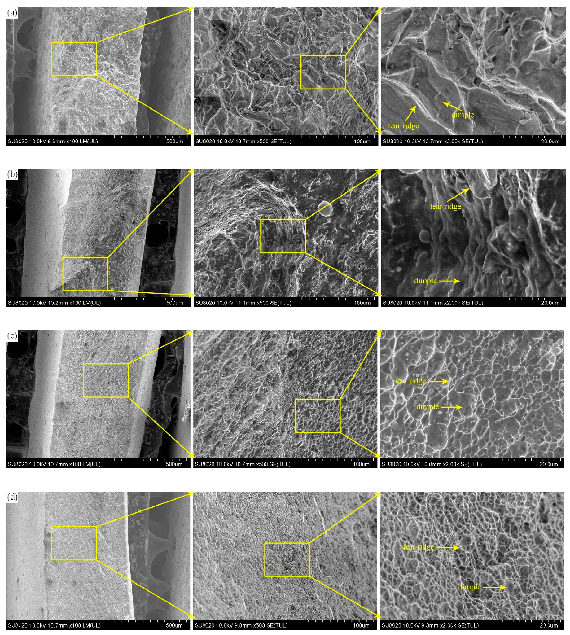
Although the mechanical properties of the CP Ti were improved more significantly by MDF, the fracture toughness was also critical to the resistance of crack initiation and growth. Therefore, the tensile fractured specimens are shown in Figure 9. During tensile tests, some typical fracture phenomena were observed that the fractured location was around the middle of specimen and the crack growth direction was along about 45° of the loading direction. The angle between the fracture surface and tensile axis was an important parameter to estimate modes of material failure [33]. During uniaxial tension, the maximum shear stress happened on a surface with 45° and the sample would fail on this surface if it was weak under shear in this orientation. However, because of other deformation mechanisms, such as twinning, void nucleation and propagation or texture evolution, this could deviate from the value predicted by maximum shear stress, especially for some ductile metals [34]. There was necking behavior in the specimen of as-received CP Ti, but it was not obvious in the specimens of UFG CP Ti, indicating slip dominated plasticity and subsequent damage mode. To further describe the microscopic fracture mechanisms, fractographs are shown as Figure 10.
The toughness of fracture surfaces decreased from Figure 10a–d, which meant that the specimens tolerated lessening degrees of elongation before failure appeared, but the fracture behaviors of all tensile specimens were controlled by the classical ductile fracture mechanism. There was some evidence from the presence of numerous dimples and tear ridges. In Figure 10a,b, tensile fracture surfaces of CP Ti exhibited a generally rough morphology by the large and deep dimples distributed randomly on the surface. However, in Figure 10c,d, a different failure mode was discovered for UFG CP Ti, where the small and shallow dimples presented a relatively regular pattern. Dimples were initiated probably by the dislocation mechanism [35,36]. Dislocations moved towards the grain boundary, then the dislocation density was enhanced with increasing the tensile deformation, which would result in intergranular fracture [36]. Some tear ridges corresponded to local plastic deformation at grain boundaries, which were traces of slip patterns with stripes clustered within each dimple propagation region. After several cycles of MDF, the number of dimples increased, but dimple size decreased to the scale equal or even less than the grain size. At the same time, cleavage features also appeared gradually, which was the mixed mode of fracture [37], as shown in Figure 10c,d. This was again consistent with the total ductility ratio of MDF specimens decrease.

5. Conclusions

  • With the increase of MDF cycles, grains were finer and more homogeneous, with less in the way of defects. Initial polygonal grains had disappeared, and the GBs became ambiguous.
  • By TEM, grain size and dislocation density decreased with increasing the cycles of MDF. The mean grain size was about 1 μm, 500 nm and 200 nm respectively after one, two and three cycles of MDF. In all MDF specimens, there was high dislocation density, but twins were not directly found. Therefore, within this study, dynamic recrystallization was the dominant grain refinement mechanism of MDF CP Ti.
  • For fractographs, there were numerous dimples and tear ridges in UFG CP Ti. By increasing the cycles of MDF, this increased the number of dimples, but then the dimple size decreased to the scale equal to, or even less than, the grain size, and cleavage features also appeared gradually. In other words, the fracture mode of UFG CP Ti was mixed.

Author Contributions

Conceptualization, Z.Z. and T.S.; methodology, X.Z.; validation, X.Z., and L.X.; investigation, L.H.; data curation, L.X.; writing—original draft preparation, X.Z.; writing—review and editing, Z.Z.; project administration, T.S.; funding acquisition, Z.Z. and T.S.

Funding

This research was funded by National Natural Science Foundation of China: No. 51465002 and 51675110.

Acknowledgments

This research was funded by National Natural Science Foundation of China, grant number 51465002 and 51675110.

Conflicts of Interest

The authors declare no conflict of interest.

References

  1. Kim, H.; Lim, S.; Yeo, I.; Kim, W. Stress-induced martensitic transformation of metastable β-titanium alloy. Mater. Sci. Eng. A 2007, 450, 322–325. [Google Scholar] [CrossRef]
  2. Li, C.; Chen, J.; Li, W.; He, J.J.; Qiu, W.; Ren, Y.J.; Chen, J.L.; Chen, J.H. Study on the relationship between microstructure and mechanical property in a metastable β titanium alloy. J. Alloys Compd. 2015, 627, 222–230. [Google Scholar] [CrossRef]
  3. Jiang, Z.; Wang, P.; Li, D.; Li, Y. The evolutions of microstructure and mechanical properties of 2.25Cr-1Mo-0.25V steel with different initial microstructures during tempering. Mater. Sci. Eng. A Struct. Mater. 2017, 699, 165–175. [Google Scholar] [CrossRef]
  4. Mikhaylovskaya, A.; Kotov, A.; Kishchik, M.; Prosviryakov, A.; Portnoy, V. The effect of isothermal Multi-Directional forging on the grain structure, superplasticity, and mechanical properties of the conventional Al–Mg-Based alloy. Metals 2019, 9, 33. [Google Scholar] [CrossRef]
  5. Cai, C.; LingHui, S.; XingHao, D.; BaoLin, W. Enhanced mechanical property of AZ31B magnesium alloy processed by multi-directional forging method. Mater. Charact. 2017, 131, 72–77. [Google Scholar] [CrossRef]
  6. Jiang, M.G.; Yan, H.; Chen, R.S. Microstructure, texture and mechanical properties in an as-cast AZ61 Mg alloy during multi-directional impact forging and subsequent heat treatment. Mater. Des. 2015, 87, 891–900. [Google Scholar] [CrossRef]
  7. Wang, B.; Liu, C.; Gao, Y.; Jiang, S.; Chen, Z.; Luo, Z. Microstructure evolution and mechanical properties of Mg-Gd-Y-Ag-Zr alloy fabricated by multidirectional forging and ageing treatment. Mater. Sci. Eng. A 2017, 702, 22–28. [Google Scholar] [CrossRef]
  8. Vasilev, E.; Linderov, M.; Nugmanov, D.; Sitdikov, O.; Markushev, M.; Vinogradov, A. Fatigue Performance of Mg-Zn-Zr Alloy Processed by Hot Severe Plastic Deformation. Metals 2015, 5, 2316–2327. [Google Scholar] [CrossRef] [Green Version]
  9. Khani Moghanaki, S.; Kazeminezhad, M.; Logé, R. Mechanical behavior and texture development of over-aged and solution treated Al-Cu-Mg alloy during multi-directional forging. Mater. Charact. 2018, 135, 221–227. [Google Scholar] [CrossRef]
  10. Li, K.; Injeti, V.S.Y.; Trivedi, P.; Murr, L.E.; Misra, R.D.K. Nanoscale deformation of multiaxially forged ultrafine-grained Mg-2Zn-2Gd alloy with high strength-high ductility combination and comparison with the coarse-grained counterpart. J. Mater. Sci. Technol. 2018, 34, 311–316. [Google Scholar] [CrossRef]
  11. Boyer, R.; Welsch, G.; Collings, E. Materials Properties Handbook: Titanium Alloys; ASM International: Materials Park, OH, USA, 1998. [Google Scholar]
  12. Wang, B.; Wang, X.; Li, J. Formation and Microstructure of Ultrafine-Grained Titanium Processed by Multi-Directional Forging. J. Mater. Eng. Perform. 2016, 25, 2521–2527. [Google Scholar] [CrossRef]
  13. Xu, C.; Zhu, W. Comparison of microstructures and mechanical properties between forging and rolling processes for commercially pure titanium. Trans. Nonferrous Met. Soc. 2012, 22, 1939–1946. [Google Scholar] [CrossRef]
  14. Mironov, S.Y.; Salishchev, G.A.; Myshlyaev, M.M.; Pippan, R. Evolution of misorientation distribution during warm ‘abc’ forging of commercial-purity titanium. Mater. Sci. Eng. A 2006, 418, 257–267. [Google Scholar] [CrossRef]
  15. Zhang, D.; Li, S. Orientation dependencies of mechanical response, microstructure and texture evolution in hot compression of AZ31 magnesium alloy processed by equal channel angular extrusion. Mater. Sci. Eng. A 2011, 528, 4982–4987. [Google Scholar] [CrossRef]
  16. Ghosh, S.; Singh, A.K.; Mula, S. Effect of critical temperatures on microstructures and mechanical properties of Nb–Ti stabilized IF steel processed by multiaxial forging. Mater. Des. 2016, 100, 47–57. [Google Scholar] [CrossRef]
  17. Xia, X.; Chen, M.; Lu, Y.; Fan, F.; Zhu, C.; Huang, J.; Deng, T.; Zhu, S. Microstructure and mechanical properties of isothermal multi-axial forging formed AZ61 Mg alloy. Trans. Nonferrous Met. Soc. 2013, 23, 3186–3192. [Google Scholar] [CrossRef]
  18. Podolskiy, A.V.; Ng, H.P.; Psaruk, I.A.; Tabachnikova, E.D.; Lapovok, R. Cryogenic equal channel angular pressing of commercially pure titanium: Microstructure and properties. J. Mater. Sci. 2014, 49, 6803–6812. [Google Scholar] [CrossRef]
  19. Belyakov, A.; Tsuzaki, K.; Miura, H.; Sakai, T. Effect of initial microstructures on grain refinement in a stainless steel by large strain deformation. Acta Mater. 2003, 51, 847–861. [Google Scholar] [CrossRef]
  20. Hughes, D.A.; Chrzan, D.C.; Liu, Q.; Hansen, N. Scaling of misorientation angle distributions. Phys. Rev. Lett. 1998, 21, 4664–4667. [Google Scholar] [CrossRef]
  21. Zecevic, M.; Lebensohn, R.A.; McCabe, R.J.; Knezevic, M. Modeling of intragranular misorientation and grain fragmentation in polycrystalline materials using the viscoplastic self-consistent formulation. Int. J. Plast. 2018, 109, 193–211. [Google Scholar] [CrossRef]
  22. Chen, Q.; Lin, S.; Yang, C.; Fan, C.; Ge, H. Grain fragmentation in ultrasonic-assisted TIG weld of pure aluminum. Ultrason. Sonochem. 2017, 39, 403–413. [Google Scholar] [CrossRef] [PubMed]
  23. Suwas, S.; Beausir, B.; Tóth, L.S.; Fundenberger, J.J.; Gottstein, G. Texture evolution in commercially pure titanium after warm equal channel angular extrusion. Acta Mater. 2011, 59, 1121–1133. [Google Scholar] [CrossRef]
  24. Meredith, C.S.; Khan, A.S. The microstructural evolution and thermo-mechanical behavior of UFG Ti processed via equal channel angular pressing. J. Mater. Process. Technol. 2015, 219, 257–270. [Google Scholar] [CrossRef]
  25. Hajizadeh, K.; Eghbali, B. Effect of two-step severe plastic deformation on the microstructure and mechanical properties of commercial purity titanium. Met. Mater. Int. 2014, 20, 343–350. [Google Scholar] [CrossRef]
  26. Sanosh, K.P.; Balakrishnan, A.; Francis, L.; Kim, T.N. Vickers and Knoop Micro-hardness Behavior of Coarse-and Ultrafine-grained Titanium. J. Mater. Sci. Technol. 2010, 26, 904–907. [Google Scholar] [CrossRef]
  27. Karimi, M.; Toroghinejad, M.R.; Dutkiewicz, J. Nanostructure formation during accumulative roll bonding of commercial purity titanium. Mater. Charact. 2016, 122, 98–103. [Google Scholar] [CrossRef]
  28. Semenova, I.P.; Valiev, R.Z.; Yakushina, E.B.; Salimgareeva, G.H.; Lowe, T.C. Strength and fatigue properties enhancement in ultrafine-grained Ti produced by severe plastic deformation. J. Mater. Sci. 2008, 43, 7354–7359. [Google Scholar] [CrossRef] [Green Version]
  29. Lefebvre, S.; Devincre, B.; Hoc, T. Simulation of the Hall–Petch effect in ultra-fine grained copper. Mater. Sci. Eng. A 2005, 400–401, 150–153. [Google Scholar] [CrossRef]
  30. Sanders, P.G.; Youngdahl, C.J.; Weertman, J.R. The strength of nanocrystalline metals with and without flaws. Mater. Sci. Eng. A 1997, 234, 77–82. [Google Scholar] [CrossRef]
  31. Huang, T.; Shuai, L.; Wakeel, A.; Wu, G.; Hansen, N.; Huang, X. Strengthening mechanisms and Hall-Petch stress of ultrafine grained Al-0.3%Cu. Acta Mater. 2018, 156, 369–378. [Google Scholar] [CrossRef]
  32. Dudova, N.; Belyakov, A.; Sakai, T.; Kaibyshev, R. Dynamic recrystallization mechanisms operating in a Nie grained Al-0.3%Cr alloy under hot-to-warm working. Acta Mater. 2010, 58, 3624–3632. [Google Scholar] [CrossRef]
  33. Dutler, N.; Nejati, M.; Valley, B.; Amann, F.; Molinari, G. On the link between fracture toughness, tensile strength, and fracture process zone in anisotropic rocks. Eng. Fract. Mech. 2018, 201, 56–79. [Google Scholar] [CrossRef]
  34. Sun, X.; Guo, Y.; Wei, Q.; Li, Y.; Zhang, S. A comparative study on the microstructure and mechanical behavior of titanium: Ultrafine grain vs. coarse grain. Mater. Sci. Eng. A 2016, 669, 226–245. [Google Scholar] [CrossRef]
  35. Sun, Z.; Yang, H. Microstructure and mechanical properties of TA15 titanium alloy under multi-step local loading forming. Mater. Sci. Eng. A 2009, 523, 184–192. [Google Scholar] [CrossRef]
  36. Padap, A.K.; Chaudhari, G.P.; Nath, S.K.; Pancholi, V. Ultrafine-grained steel fabricated using warm multiaxial forging: Microstructure and mechanical properties. Mater. Sci. Eng. A 2009, 527, 110–117. [Google Scholar] [CrossRef]
  37. Ko, Y.G.; Shin, D.H.; Park, K.; Lee, C.S. An analysis of the strain hardening behavior of ultra-fine grain pure titanium. Scr. Mater. 2006, 54, 1785–1789. [Google Scholar] [CrossRef]
Figure 1. OM image showing the microstructure of as-received commercially pure titanium (CP Ti).
Metals 09 00175 g001
Figure 2. Schematic illustration showing the position of hardness measurement.
Metals 09 00175 g002
Figure 3. Macroscopic morphology of as-received and MDF (multi-directional forging) CP Ti.
Metals 09 00175 g003
Figure 4. OM images of CP Ti after MDF with (a) 1 cycle (b) 2 cycles (c) 3 cycles.
Metals 09 00175 g004
Figure 5. TEM images of CP Ti after MDF with (a) 1 cycle (b) 2 cycles (c) 3 cycles.
Metals 09 00175 g005
Figure 6. The average Vickers hardness versus the MDF cycles of CP Ti.
Metals 09 00175 g006
Figure 7. Engineering stress-strain curves of as-received and MDF CP Ti.
Metals 09 00175 g007
Figure 8. Tensile strength versus the MDF cycles.
Metals 09 00175 g008
Figure 9. Macroscopic fractural morphology of CP Ti.
Metals 09 00175 g009
Figure 10. The tensile fracture area of CP Ti with (a) as-recevied, (b) 1 cycle of MDF, (c) 2 cycles of MDF, (d) 3 cycles of MDF.
Metals 09 00175 g010