Article

Shaping of Aluminum Foam during Foaming of Precursor Using Steel Mesh with Various Opening Ratios

1
Faculty of Science and Technology, Gunma University, Kiryu 376-8515, Japan
2
Department of Mechanical Engineering, Shibaura Institute of Technology, Tokyo 135-8548, Japan
3
Institute of Industrial Science, The University of Tokyo, Tokyo 153-8505, Japan
*
Author to whom correspondence should be addressed.
Metals 2019, 9(2), 223; https://doi.org/10.3390/met9020223
Submission received: 28 December 2018 / Revised: 23 January 2019 / Accepted: 5 February 2019 / Published: 13 February 2019
(This article belongs to the Special Issue Recent Developments in Porous Metals and Metallic Foams)

Abstract

:
In this study, steel meshes with various opening ratios φ were used to shape aluminum foams during precursor foaming. The effect of φ on the heating rate and shape of the obtained aluminum foams was investigated. It was found that steel meshes with various opening ratios can be used to shape aluminum foam. There is no significant effect on the pore structures of the obtained aluminum foams when upward expansion is restricted during foaming, regardless of the value of φ. The meshes with higher φ clearly transfer the mesh pattern onto the surface of the aluminum foam but require a shorter foaming time. In contrast, the lower-φ meshes produce aluminum foams with a smoother surface but a longer foaming time is required.

1. Introduction

The shaping of aluminum (Al) foam is required in various industrial fields where lightweight materials are desired, such as the vehicle [1] and building industries [2]. The foaming of precursors in a mold by heat treatment is a popular method of fabricating Al foams with complex shapes [3,4,5]. The precursor [6,7] is solid Al containing a homogeneously distributed blowing agent. Upon heat treatment of the precursor, the blowing agent decomposes and the released gases expand the Al. In this foaming process, the mold is also heated, which causes a significant energy loss. Also, the fabrication of a mold with a complex shape is a very time-consuming process, increasing the cost of the mold.
Hangai et al. demonstrated that the precursor can be foamed by optical heating using halogen lamps [8]. In addition, Al foam can be shaped by a steel mesh with an opening ratio of 66.9% as a mold during the foaming of the precursor [9,10]. The foaming was induced by the light passing through the openings of the steel mesh. Although the mesh pattern was observed on the surface of the obtained Al foam, little protrusion of the Al foam from the mesh openings was observed during the foaming owing to the surface tension of the Al foam.
In this study, steel meshes with various opening ratios were used to shape Al foam. Al foam with a smoother surface can be expected by using a mesh with a lower opening ratio, but a longer foaming time may be required owing to the reduced amount of light. First, the relationship between the rate of increase in the temperature during the heat treatment of Al without a blowing agent and the opening ratio of various steel meshes was investigated. In addition, Al foams with a plane surface were fabricated while restricting upward expansion using various steel meshes. The forming behavior, surface mesh pattern, and pore structures of the obtained Al foams were investigated. On the basis of these experiments, the effect of the opening ratio of the steel mesh on the heating rate and shape of the obtained Al foams is discussed.

2. Materials and Methods

2.1. Rate of Temperature Increase

Figure 1 shows a schematic illustration of the heat treatment of an Al sample by optical heating. An ADC12 (Al–Si–Cu die-casting alloy, solidus and liquidus temperatures of 515 °C and 580 °C [11], respectively, thermal conductivity of 92 W/m·°C) sample without a blowing agent having dimensions of 15 mm × 15 mm × 6 mm was used. The ADC12 sample was placed on a ceramic honeycomb with a thermocouple placed 3 mm from the bottom center of the sample to measure the temperature at the center of the sample. A halogen lamp was used for the optical heating. The current and voltage of the halogen lamp during the heat treatment were 7.0 A and 48 V, respectively. The distance between the lamp and the upper surface of the ADC12 sample was 50 mm.
The steel mesh was held between the halogen lamp and the ADC12 sample by clamps, which were placed sufficiently far from the sample for their effect to be disregarded during the heat treatment. The distance between the steel mesh and the surface of the ADC12 sample was 25 mm. Four steel meshes made of SUS304 stainless steel with different opening ratios φ, as shown in Figure 2, were used. Table 1 shows the specifications of these steel meshes. Free foaming without the use of a steel mesh was also conducted (φ = 100%). The lamp was turned off when the temperature reached 400 °C. Then, the ADC12 sample was cooled to below 100 °C, the steel mesh was changed, and the next temperature measurement was started. A temperature of 400 °C (lower than the foaming temperature) was selected to neglect the effect of heat dissipation and to prevent the change of the shape of the ADC12 sample by softening of the sample during heat treatment. These experiments with the changing of the steel mesh were repeated three times.

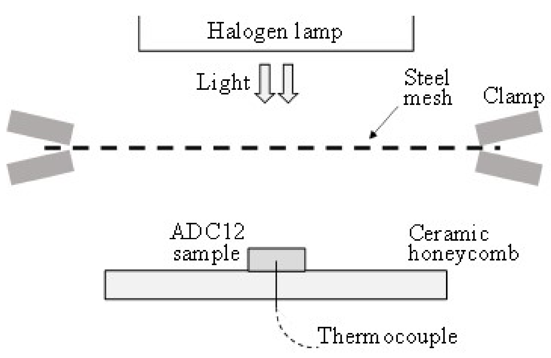
2.2. Shaping of ADC12 Foam by Steel Mesh

Figure 3 shows a schematic illustration of the foaming of the ADC12 precursor by light through the steel mesh and the restriction of the upward expansion by the steel mesh. The ADC12 precursors were fabricated by the friction stir welding (FSW) route in accordance with Ref. [12,13,14]. ADC12 die-casting plates [15] were used as the starting material. Titanium(II) hydride (TiH2, <45 μm, 1 wt %) and α-alumina (Al2O3, ~1 μm, 5 wt %) were used as the blowing agent and stabilization agent, respectively. Precursors with dimensions of 15 mm × 15 mm × 6 mm were obtained.
The setup of the heating equipment was the same as in Figure 1, except that the steel mesh was held by spacers and no thermocouple was used. The steel mesh was placed on 10-mm-thick steel spacers, then 15-mm-thick steel weights were placed on the steel mesh to prevent it from moving upward owing to the foaming force of the precursor. The distance between the spacers on both sides of the precursor was as short as possible to avoid the deflection of the steel mesh owing to its weight and thermal expansion without shielding the irradiating light. The thermocouple was not used because the use of the thermocouple may have affected the pore structures of the obtained ADC12 foam. The effect of using spacers on the heating rate of the precursor was not considered in this study. The distance between the upper surface of the precursor and the steel mesh was set to 4 mm, which resulted in the obtained ADC12 foam having a thickness of 10 mm. The foaming was stopped when the pores began to burst owing to the release of the generated gases from the surface of the precursor. Foaming experiments were conducted twice for each φ.
The pore structures of the obtained ADC12 foam were nondestructively observed by microfocus X-ray computed tomography (CT) equipment in accordance with Ref. [16]. In addition, the porosity of the entire ADC12 foam was evaluated by Archimedes’ principle.

3. Results and Discussion

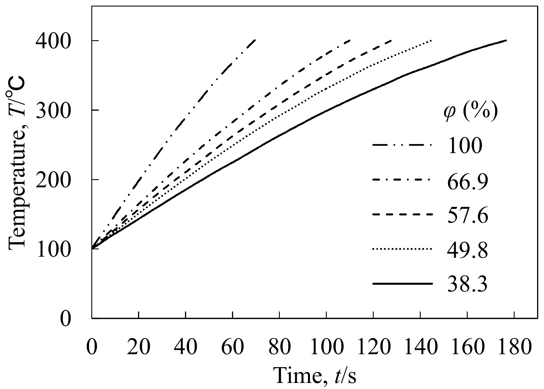
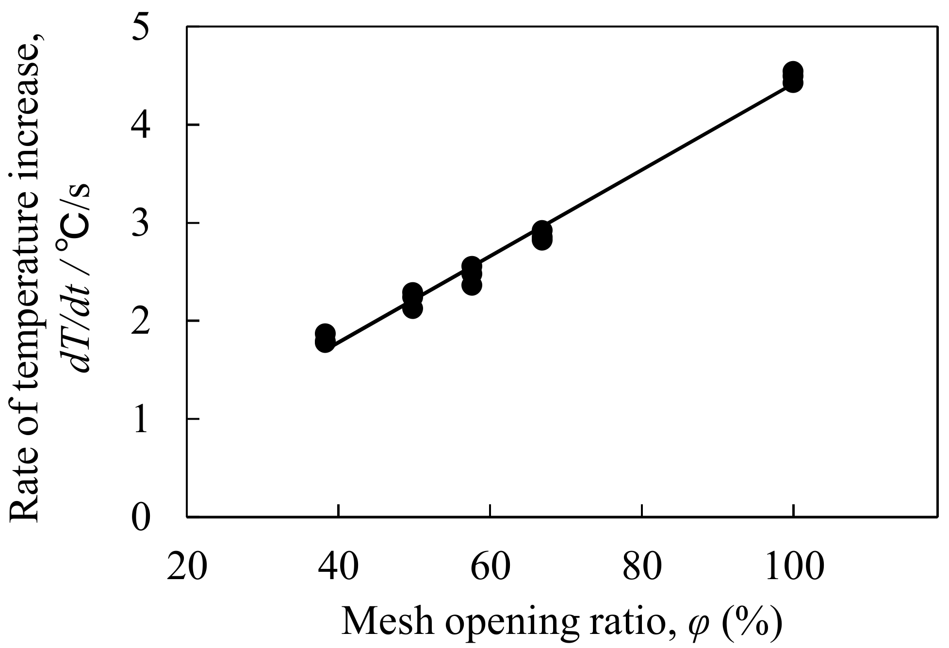
3.1. Rate of Temperature Increase

Figure 4 shows the relationship between the temperature of the ADC12 sample T and the heating time t for each φ. t = 0 s was defined as the time when the temperature reached 100 °C. It was found that the temperature reached 400 °C first when no mesh was used (φ = 100%), and the time required to reach 400 °C increased with decreasing φ. Figure 5 shows the relationship between the rate of temperature increase dT/dt and φ, where dT/dt was evaluated as the slope between temperatures of 200 and 300 °C in Figure 4. It was found that dT/dt vs. φ had a strong correlation with a correlation coefficient of 0.994. These results indicate that the amount of light passing through the mesh used for the heat treatment of the sample was significantly affected by φ.

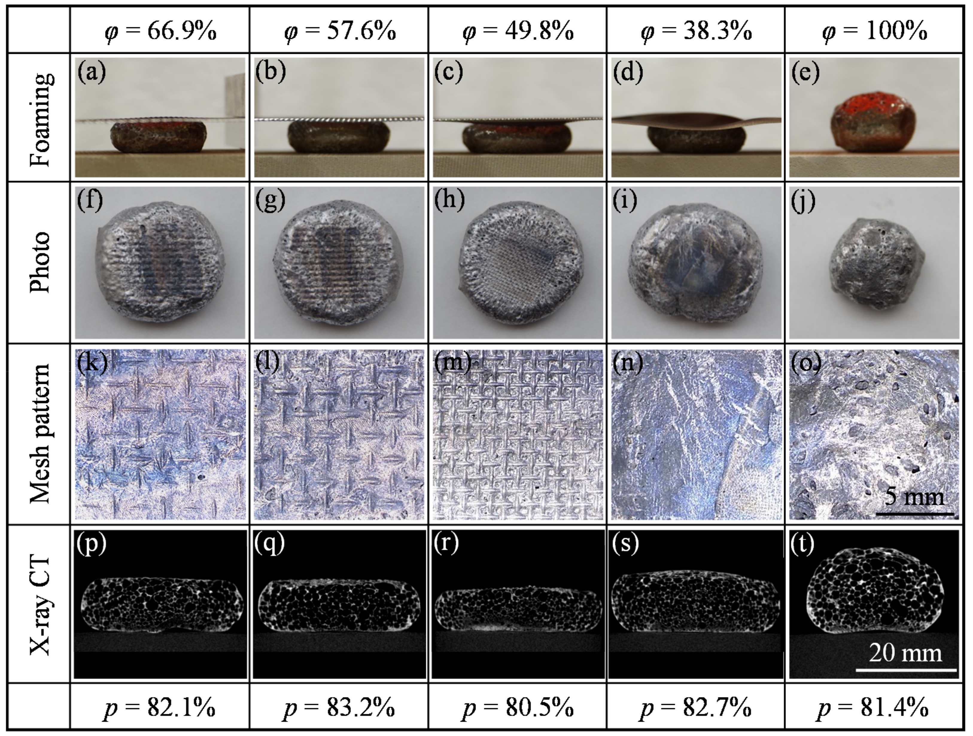
3.2. Shaping of ADC12 Foam by Steel Mesh

Figure 6 shows the foaming behavior of the ADC12 precursor when using a steel mesh with φ = 66.9%. Figure 6a shows the precursor immediately before the light was turned on and the heat treatment began. Figure 6b shows the precursor during the foaming approximately when it first came in contact with the steel mesh. Figure 6c shows the ADC12 foam shortly after the light was turned off and the foaming stopped. The precursor was successfully foamed by the light passing through the steel mesh and the upward expansion of the ADC12 foam during foaming was restricted by the steel mesh, consistent with our previous study [9].
Figure 7a–e shows the foamed Al shortly after the light was turned off for each φ. The precursor was successfully foamed by the light passing through the steel mesh, and the expansion of the ADC12 foam during foaming was restricted by the force applied by the steel mesh regardless of the kind of steel mesh used in this study. However, significant deflection of the steel mesh was observed for φ = 49.8% and φ = 38.3% owing to the thermal expansion of the steel mesh. The light was partly irradiated on the steel mesh. Thermal expansion only occurred in parts where light was irradiated which caused deflection of the steel mesh. Therefore, significant deflection of the steel mesh occurred for the meshes with lower φ having densely aligned steel wires.
Figure 7f–j shows the appearance of the obtained ADC12 foams and Figure 7k–o shows enlarged images of their surfaces in contact with the steel mesh. ADC12 foam with a plane surface was obtained by using a mesh with a higher φ. The mesh pattern was transferred to the surface of the ADC12 foams in contact with the steel mesh, and the surface of the ADC12 foams was smoother than that of the foam obtained for φ = 100% (Figure 7o). The surface of the ADC12 foam became increasingly smooth with decreasing φ owing to the smaller sieve mesh size as shown in Table 1.
Figure 7p–t shows cross-sectional X-ray CT images of the obtained ADC12 foams. Black and white regions indicate pores and Al, respectively. The upper and lower surfaces were in contact with the steel mesh and the ceramic honeycomb during the foaming process, respectively. It was found that there is no significant effect on the pore structures of the obtained ADC12 foams upon restricting upward expansion during foaming, regardless of the value of φ. Porosities of around 80% were observed for every sample, similar to that obtained by free foaming and by the precursor foaming process in Ref. [5,17]. The thickness of the ADC12 foams was similar to that of the steel spacers for φ = 66.9% and 57.6% but different for φ = 49.8% and 38.3% owing to the deflection of the steel mesh. The effect of thermal strain on the accuracy of the shape of the obtained Al foam is an important issue even in the case of using a general rigid mold for shaping Al foam. Deflection of the steel mesh during the foaming process may be prevented by preheating the entire steel mesh. This issue should be investigated in a future study.

4. Conclusions

In this study, steel meshes with various opening ratios φ were used to shape ADC12 foams. It was found that all the steel meshes used in this study can be used to shape ADC12 foam during foaming. There was no significant effect on the pore structures of obtained ADC12 foams when upward expansion was restricted during foaming, regardless of the value of φ. The meshes with higher φ clearly transferred the mesh pattern onto the surface of the ADC12 foam but required a shorter foaming time. In contrast, the lower-φ meshes produced ADC12 foams with a smoother surface but a longer foaming time was required.

Author Contributions

Y.H. and K.A. elaborated the research idea. Y.H. wrote this manuscript. R.N. and M.O. performed the experimental work and contributed to the discussion of the experimental results. T.U. and N.Y. performed literature review and contributed to the discussion of the experimental results.

Acknowledgments

This research is (partially) supported by the Matching Planner Program from Japan Science and Technology Agency, JST and The Light Metal Education Foundation, Inc.

Conflicts of Interest

The authors declare no conflict of interest.

References

  1. Banhart, J. Aluminium foams for lighter vehicles. Int. J. Veh. Des. 2005, 37, 114–125. [Google Scholar] [CrossRef]
  2. García-Moreno, F. Commercial applications of metal foams: Their properties and production. Materials 2016, 9, 85. [Google Scholar] [CrossRef] [PubMed]
  3. Schäffler, P. A New Generation of Materials and Their Production Methods. In Porous Metals and Metal Foaming Technology; Nakajima, H., Kanetake, N., Eds.; The Japan Institute of Metals: Sendai, Japan, 2005; pp. 153–156. [Google Scholar]
  4. Reglero, J.A.; Rodriguez-Perez, M.A.; Solorzano, E.; de Saja, J.A. Aluminium foams as a filler for leading edges: Improvements in the mechanical behaviour under bird strike impact tests. Mater. Des. 2011, 32, 907–910. [Google Scholar] [CrossRef]
  5. Banhart, J. Light-metal foams—History of innovation and technological challenges. Adv. Eng. Mater. 2013, 15, 82–111. [Google Scholar] [CrossRef]
  6. Baumgartner, F.; Duarte, I.; Banhart, J. Industrialization of powder compact foaming process. Adv. Eng. Mater. 2000, 2, 168–174. [Google Scholar] [CrossRef]
  7. Duarte, I.; Banhart, J. A study of aluminium foam formation—Kinetics and microstructure. Acta Mater. 2000, 48, 2349–2362. [Google Scholar] [CrossRef]
  8. Hangai, Y.; Amagai, K.; Tsurumi, N.; Omachi, K.; Shimizu, K.; Akimoto, K.; Utsunomiya, T.; Yoshikawa, N. Forming of aluminum foam using light-transmitting material as die during foaming by optical heating. Mater. Trans. 2018, 59, 1854–1859. [Google Scholar] [CrossRef]
  9. Hangai, Y.; Amagai, K.; Omachi, K.; Tsurumi, N.; Utsunomiya, T.; Yoshikawa, N. Forming of aluminum foam using steel mesh as die during foaming of precursor by optical heating. Opt. Laser Technol. 2018, 108, 496–501. [Google Scholar] [CrossRef]
  10. Hangai, Y.; Tsurumi, N.; Amagai, K.; Utsunomiya, T.; Yoshikawa, N. Shaping of aluminum foam during foaming process using stainless steel mesh mold. J. Japan Inst. Metals 2018, 82, 484–486. [Google Scholar] [CrossRef]
  11. The Japan Institute of Light Metals. Structures and Properties of Aluminum; The Japan Institute of Light Metals: Tokyo, Japan, 1991. [Google Scholar]
  12. Hangai, Y.; Utsunomiya, T.; Hasegawa, M. Effect of tool rotating rate on foaming properties of porous aluminum fabricated by using friction stir processing. J. Mater. Process. Technol. 2010, 210, 288–292. [Google Scholar] [CrossRef]
  13. Azizieh, M.; Pourmansouri, R.; Balak, Z.; Kafashan, H.; Mazaheri, M.; Kim, H.S. The application of friction stir processing to the fabrication of magnesium-based foams. Arch. Metall. Mater. 2017, 62, 1957–1962. [Google Scholar] [CrossRef]
  14. Papantoniou, I.G.; Kyriakopoulou, H.P.; Pantelis, D.I.; Athanasiou-Ioannou, A.; Manolakos, D.E. Manufacturing process of AA5083/nano-gamma Al2O3 localized composite metal foam fabricated by friction stir processing route (FSP) and microstructural characterization. J. Mater. Sci. 2018, 53, 3817–3835. [Google Scholar] [CrossRef]
  15. Hangai, Y.; Kamada, H.; Utsunomiya, T.; Kitahara, S.; Kuwazuru, O.; Yoshikawa, N. Aluminum alloy foam core sandwich panels fabricated from die casting aluminum alloy by friction stir welding route. J. Mater. Process. Technol. 2014, 214, 1928–1934. [Google Scholar] [CrossRef]
  16. Hangai, Y.; Takahashi, K.; Yamaguchi, R.; Utsunomiya, T.; Kitahara, S.; Kuwazuru, O.; Yoshikawa, N. Nondestructive observation of pore structure deformation behavior of functionally graded aluminum foam by X-ray computed tomography. Mater. Sci. Eng. A 2012, 556, 678–684. [Google Scholar] [CrossRef]
  17. Kobashi, M.; Noguchi, M.; Kanetake, N. Observation of foaming behavior for rolled sheet precursors made of various aluminum powders. Mater. Trans. 2011, 52, 934–938. [Google Scholar] [CrossRef]
Figure 1. Schematic illustration of heat treatment of ADC12 sample.
Metals 09 00223 g001
Figure 2. Steel meshes used in this study: (a) φ = 66.9%. (b) φ = 57.6%. (c) φ = 49.8%. (d) φ = 38.3%.
Metals 09 00223 g002
Figure 3. Schematic illustration of foaming ADC12 precursor.
Metals 09 00223 g003
Figure 4. Relationship between temperature and time during heat treatment.
Metals 09 00223 g004
Figure 5. Relationship between rate of temperature increase and mesh opening ratio during heat treatment.
Metals 09 00223 g005
Figure 6. Foaming behavior of ADC12 precursor when using steel mesh with φ = 66.9%: (a) initial precursor, (b) during foaming, (c) after foaming.
Metals 09 00223 g006
Figure 7. (a)–(e) Foaming behavior of ADC12 precursor using steel mesh, (f)–(j) Appearance of obtained ADC12 foams, (k)–(o) their surface mesh patterns, and (p)–(t) their cross-sectional X-ray CT images.
Metals 09 00223 g007
Table 1. Specifications of the steel meshes shown in Figure 2.
Opening Ratio,
φ(%)
Wire Diameter,
b/mm
Sieve Mesh Size,
a/mm
(a)66.90.291.30
(b)57.60.341.07
(c)49.80.250.60
(d)38.30.080.13

