Article

Effects of Al and Heat Treatment on the Microstructure and Hardness of Ti–Al Synthesized via In Situ Melting using LENS

by
Monnamme Tlotleng
1,2,* and
Sisa Pityana
1,3
1
Additive Manufacturing Research Group, Laser Enabled Manufacturing, National Laser Centre CSIR, Pretoria 0001, South Africa
2
Department of Mechanical Engineering Science, Faculty of Engineering and the Built Environment, University of Johannesburg, Auckland Park Campus, Johannesburg 2006, South Africa
3
Department of Chemical, Metallurgy and Materials Engineering, Faculty of Engineering and the Built Environment, Tshwane University of Technology, Pretoria 0001, South Africa
*
Author to whom correspondence should be addressed.
Metals 2019, 9(6), 623; https://doi.org/10.3390/met9060623
Submission received: 30 March 2019 / Revised: 17 April 2019 / Accepted: 26 April 2019 / Published: 29 May 2019

Abstract

:
Producing alloys via in-situ laser alloying approach is becoming very easy and a topical issue in the field of laser additive manufacturing. Several studies have emerged, accompanied by a statement by Gasper et al. (2017), who reported the economic benefits and cost savings that can be related to 3D printing of the additive manufacturing (AM) structure using the said in situ synthesis approach. They studied the laser in situ reactive synthesis of producing titanium aluminide (Ti–Al) from elemental powders using the laser materials deposition (LMD) process. This paper highlights how the functional grade Ti–Al alloys can be produced in a single flight using the 850-R Optomec Laser Engineering Net Shaping (LENS) system. The effects of the Al content in the as-built and heat-treated samples were investigated. The as-built samples were cracked, inhomogeneous, and had visible inter-layer boundaries due to the segregation of the alloying elements and different heat profiles that are typically experienced during 3D printing. These characteristics led to wavy hardness profiles. Heat-treated samples were the least hard when compared to the as-built samples and had a homogenized microstructure. Samples with a duplex microstructure were, in particular, the least hard, indicating that they would have better ductility than others. The outcomes of this study show that a structure with different composition can be fabricated with the LENS system. This would lead to adaptive structures being used, especially in the high temperature applications where a structure would have to withstand low and high temperatures during use.

Graphical Abstract

1. Introduction

Intermetallic titanium aluminide (Ti–Al) alloys have comparable and superior properties over nickel super-alloys, which make them attractive for industries such as aerospace, automotive, and energy. Their low density, high strength, excellent oxidation resistance [1,2,3,4], and other thermo-mechanical properties [5,6,7,8] endorse them to serve as outstanding materials for structures, or just as high temperature barrier coatings. This family of intermetallic alloys can also be used in tissue engineering [9] over grade five titanium alloy. Depending on the method and conditions of processing, a desirable composition and microstructure can be obtained [8]. It is understood that gamma (γ) and dual-phase alloy (γ + α2) microstructures of Ti–Al are necessary for structural engineering. However, these phases are also said to be crack-sensitive and have poor tensile properties at room temperature. The lack of room temperature ductility makes it difficult to process and engineer [10]. The benefits of resolving this would lead to weight reduction in aerospace parts, thereby improving efficiency and reducing costs in operation [11].
Since their early discovery, research in the field of Ti–Al has been devoted toward improving their ductility. This was accomplished through micro-alloying with stabilizing metals, such as chromium, manganese, and others. However, their processing using conventional methods has not led to successful structures being fabricated, hence the need to look at different methods and approaches. A comprehensive review on Ti–Al alloys was published by Nochovnaya et al. [12]. They concluded that resolving the brittleness of Ti–Al alloys would require hot pressure treatments (e.g., hot isostatic pressing (HIP)) post-casting. These methods are, however, expensive to set-up [11] and therefore can be limiting. HIP is necessary to transform the microstructure of a cast Ti–Al component from a lamellar microstructure, which is poor in performance, to a duplex microstructure, which is regarded as having improved ductility and thermo-mechanical properties [13,14]. Kothari et al. [10] concisely summarized the microstructures of the duplex phase Ti–Al alloy and the factors that affect their mechanical properties. Couturier and Escaravage [15] highlighted the required properties and developmental needs for high-temperature alloys for future reactors. They recommended that future materials be adaptive under operational and ever-changing environments. Ti–Al alloys, or their functional graded materials (FGMs), could serve this purpose [16,17].
Casting and powder-bed additive manufacturing systems, like electron beam melting and selective laser melting, cannot be used successfully [18] or are used with difficulty [19] in the production of FGM structures, but laser metal deposition (LMD) and direct metals deposition (DMD) techniques can. It is probably sound reasoning that, to date, reported studies on 3D printed Ti–Al structures have mainly been on pre-alloyed Ti–Al powders as opposed to elemental powders [20,21,22,23,24,25,26,27,28,29,30,31,32,33,34,35,36,37,38]. Until recently, Tlotleng et al. [39], Gasper et al. [17], and Hoosain et al. [40], among others, have used a laser source beam to study the possibilities of producing Ti–Al alloys by means of an “in situ synthesis” approach. This approach uses a laser melt-pool to melt (thermodynamics) and mix (reaction kinetics) the depositing elemental metallic powders into an alloy upon cooling. This melt-pool serves as a “reactor vessel or mold”, where the depositing feedstock is injected and reacted. During alloying, it is deemed necessary that the melt-pool temperature (thermodynamics) and melt-pool flow dynamics (kinetics) must be stable and understood. A thermal camera and pyrometer are used for this purpose.
Wang and Dahms [1] are probably the first to have used the reactive synthesis method to demonstrate the mixing kinetics of elemental Ti and Al powders into a γ-Ti–Al alloy. Ti–Al alloys (at.%), in their ternary or quaternary state, are the most favourable compositions for structural engineering [32]. These alloys include general electric (Ti-48Al-2Cr-2Nb), high niobium containing (TNB), and niobium and molybdenum containing (TNM), among others. Following on the works of Tlotleng et al. [39], Gasper et al. [17], and Hoosain et al. [40], among others, Tlotleng [10] reported a γ-Ti48Al (at.%) alloy post-heat treatment. This alloy was fabricated using the LENS platform via in-situ laser alloying. However, they did not fully characterize how a LENS system can be used in producing graded microstructures of Ti–Al in a single process by adjusting or varying the Al content by offsetting the revolutions per minute (rpm) while keeping Ti rpm, laser power, and head depositing speed fixed. These results are reported for the first time in this paper. This paper reports on the effects of Al content and post-heat treatment on the microstructure of binary Ti–Al alloys that were synthesized via in-situ laser alloying using 850-R Optomec LENS system (Optomec, Albuquerque, NM, USA). The microstructure and hardness of the alloy(s) are reported.

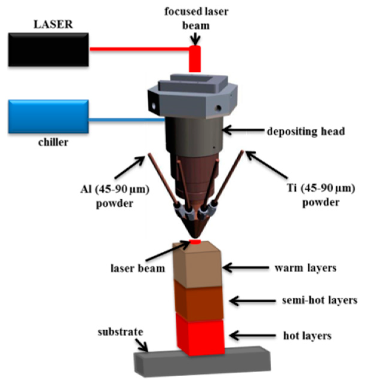
2. Materials and Methods

Both pure Al and Ti powders were used as received. The powders were spherical and had a particle size distribution of 45–90 µm. They were both supplied by TLS, Technik GmbH & Co (Bitterfeld-Wolfen, Germany). Ti-6Al-4V base plates with 70 × 70 × 5 mm3 dimensions were used as substrates, onto which the powders were concurrently deposited. Before deposition, the substrates were sand-blasted and then cleaned with acetone.
The Optomec LENS, model 850-R, system was used to manufacture the Ti–Al cube samples. This system used IPG fiber laser with a maximum power output of 1000 W. The fiber was connected to the depositing/cladding head of the LENS and it was controlled automatically from a computer work-station that used an Optomec application software control, version 3.1.6 (Optomce, Albuquerque, NM, USA). The set-up is depicted in Figure 1.
The Optomec control software was used to automatically control and operate the LENS deposition head, laser beam, and powder hoppers. Due to this capability, it is possible that feedstocks can be deposited and printed simultaneously. Most importantly, this capability allows for experiments on FGMs and in-situ laser alloying to be conducted. In this paper, in-situ laser alloying was studied.
The schematic shown in Figure 1 illustrates that the powder hoppers, which are identified as Al and Ti powders, were attached to the frame of the LENS platform. Before in-situ laser alloying experiments were commenced, powder flow measurements on Al were conducted. The results are reported in Table 1 against the set rotational speed (rpm). These flow measurements were obtained when the centre purge gas and carrier gas flow rates were kept constant at 25 and 5 L/min, respectively. Argon was used as both the centre purge and carrier gas.
During manufacturing, the Ti powder mass flowrate was kept constant at 4.96 g/min. This allowed for the investigation on the effect of Al content on the resulting Ti–Al microstructure. The process parameters are summarized in Table 2.
Post-manufacturing, the samples were cut and prepared for metallographic observation in the as-built and post-heat treatment states. Heat treatment was performed on the samples for stress relief, microstructural homogenization, and phase precipitation. It is well established that the as-built samples have internal residual stress and that elemental segregation during alloying would lead to a heterogeneous microstructure. The phase precipitation was attained in accordance with the binary Ti–Al phase diagram (Figure 2).
Heat treatment was conducted using a Carbolite tube furnace in an argon-rich environment. The samples were heated to a temperature of about 1200 °C at the ramping rate of 20 °C/min and held for 2 h before furnace cooling. The samples were mounted in a black resin and polished with OP-S suspension to 0.04 micron surface finish using Struers TegrsForce-5 auto/manual polisher (Cleveland, OH, USA). The samples were etched by immersing them into Krolls’ reagent for few seconds.
Olympus BX51M (Feasterville-Trevose, PA, USA), which was mounted on SC30 camera, was used for microstructural visualisation, while the Joel, JSM-6010Plus/LAM scanning electron microscope (SEM) (Peabody, MA, USA), equipped with energy dispersive X-ray, was used for microstructural and chemical composition analyses. Micro-hardness was measured as HV0.5 using the Zwick/Roell (ZHVµ) Vickers’ micro-hardness tester machine (Zwick Roell AG, Ulm, Germany). During indentation, pin-loading of 500 gf and a dwelling time of 10 s was used. Indents were spaced at 200 µm from each other. Measurements were taken on the left-side, middle, and right-side of the build. The average hardness was used to plot the hardness profiles and to determine the overall hardness value of the samples.

3. Results and Discussion

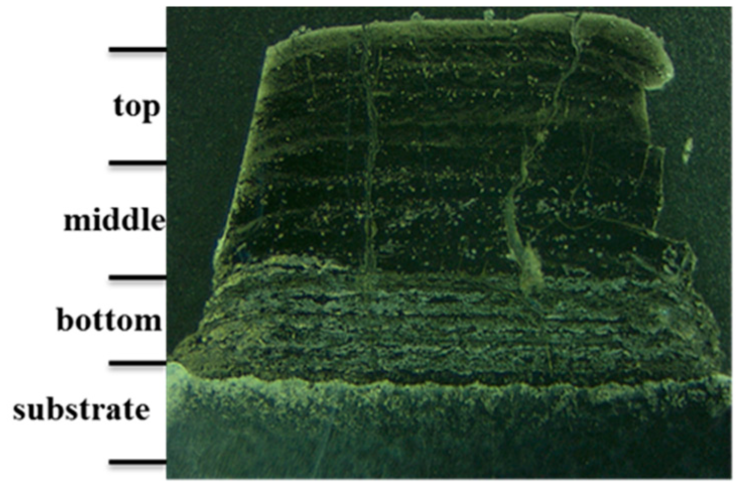
3.1. As-Built Samples

Using process parameters reported in Table 2, Ti–Al cube samples with different compositions were produced. The produced cube samples are shown in Figure 3.
It was shown in Figure 1 earlier that during laser metal deposition, the produced sample/cube would have different heating profiles, which is a result of accumulative heating during laser 3D printing. The heat profile of the as-built cubes will always be such that it is hot at the bottom in comparison to the middle and top parts of the build. This results in the different layers having different textures or a completely heterogeneous microstructure, hence post-heat treatment is a requirement for laser 3D printed parts. In addition, due to excess heating during sample building, the resulting build is always characterized by cracks, seen in Figure 4.
Figure 4 shows, in addition to the resulting cracks and roughness, different layers and inter-layer boundary regions in the as-built cube sample. The heterogeneity in the structure of the as-built sample is attributed to the segregation of alloying elements during processing and different heat profiles due to fast cooling rates experienced by every layer during layer-by-layer deposition [4].
Cracking, which is due to the brittleness of the alloy, and residual stress build in the sample is a topical issue in this research field. Most researchers working in this field are currently developing printing strategies or implementing technology capabilities which would unlock the possibility of producing a crack-free Ti–Al build [20]. The addition of a heating stage for substrate pre-heating and heat retention during printing are necessary during the manufacturing of Ti–Al samples. Rittinghaus and co-workers [4] explained that an online monitoring system, which would allow for the observation of melt-pool dynamics and the monitoring of temperature during 3D printing, is a must-have tool if inhomogeneity in the as-built samples is to be resolved and if heat-profiles of every depositing layer are to be controlled and maintained throughout sample manufacturing. Sharma et al. [20] reviewed other possibilities of producing a crack-free Ti–Al sample. It should be noted that the samples that were being studied here were not produced with any such proposed systems in place, but in the future this will be taken into consideration.

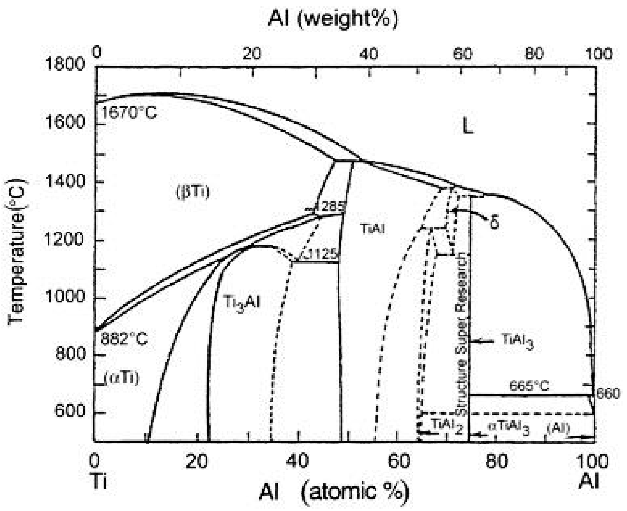
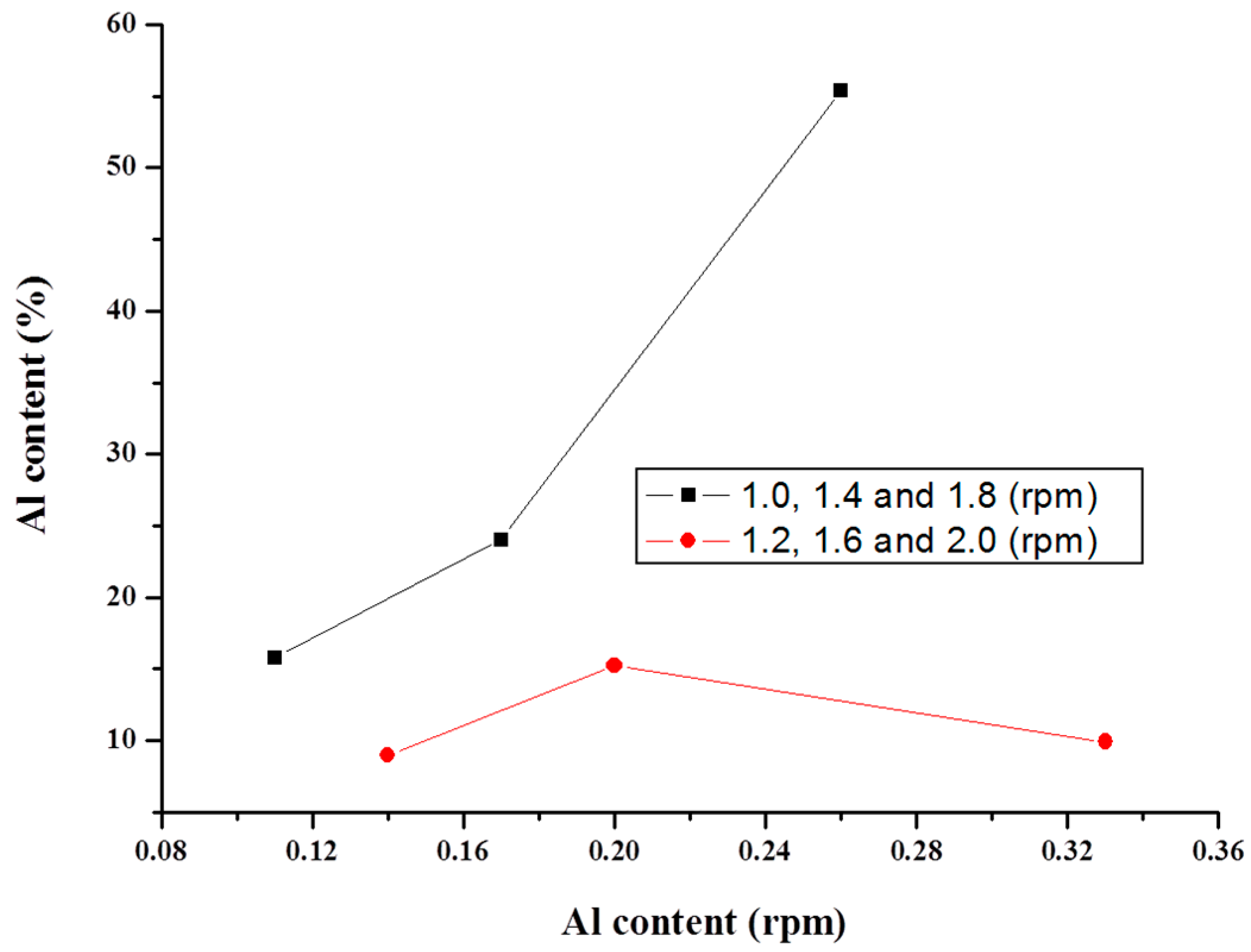
3.2. Chemical Composition and Microstructure

The microstructures and Al content (at.%) of the as-built Ti–Al samples are reported in Table 3 and Figure 5, respectively. Al content in the as-built sample supposedly had to increase linearly with the increase in set rpm, but the EDS measurements proved otherwise. The Al content in the as-built samples varied considerably, as reported in Table 3.
Table 3 reports that the highest value of Al is for samples E and C, followed by samples A and D, and the lowest for samples B and F. Rittinghaus et al. [4] reported an increase in the Al content in the as-built Ti–Al alloys. They credited the LMD process for this observation since, generally, the electron beam melting process achieved an Al loss in the as-built samples. The inconsistency in the Al content, as reported in Table 3, suggests that Al content could have vaporized during the build, but this cannot be confirmed because the online monitoring system was not used to monitor the temperature profiles of the samples during printing. Moreover, since the same stand-off distance was used during deposition, the effects of particle bow shock, nozzle fouling, or mass loss in general can be ruled out completely [32]. The probable cause of this observation could be in the particle size distribution, but, since the image of the plume was not captured during manufacturing for processing and interpretation, this would be an unjustified conclusion. This occurrence, however, requires an explanation and should be looked into in the future. For now, the only plausible explanation for this observation is in the dissolution kinetics (reaction mechanism) of Al into the Ti matrix [1], or the inconsistency of the system to feed a similar increment of Al for 1.2, 1.6, and 2.0 set rpm [30], as shown in Figure 5. This increment was, on average, 0.08 g/min for 1.0, 1.4, and 1.8 set rpm values.
Microstructures of the as-built samples are reported in Figure 6.
The microstructures of the as-built samples, as reported in Figure 6, look to be heterogeneous and had visible bands/layers. Sample E shows partially melted powder particles. The samples are also characterized by fine microstructure and agglomerated lamellar or lamellar laths (samples A, B, and C), lamellae grains (samples D and F), and formed grains (sample E). Liu et al. [41] observed coarsening in the lamellar laths, while here the laths grew small and refined into grains with the increase in Al. The features in microstructures are resolved in the SEM images that are reported in Figure 7.
Indeed, the lamellar laths size decreased with an increase in Al content (see samples A and C). The variation in microstructures with Al content was anticipated. The microstructure of sample E has surface porosity and grains of different size (20–60 µm) and colour. The α2-grains (white) seem to be generally growing around the γ-grains (black). It is not clear, at this magnification, if there are lamellae structures inside these grains and how they are arranged. Nevertheless, given the observed features, this alloy can be classified as near-gamma before heat treatment. Samples A–C have agglomerated, thick lamellar which formed randomly (direction of growth is not obvious). The size of these lamellar decreased and became refined from sample A (thick) to sample C (thin), while the formed grains were not fully precipitated. This alloy was classified as nearly lamellar before heat treatment. Lamellar colonies that formed inside the grains can be confirmed only for samples D and F. The lamellae grains of sample F are bigger than that of sample D but are, by inspection, less than or about 20 µm. These two alloys can be classified as a duplex before heat treatment.
Reconciling results reported in Table 3 and microstructures in Figure 6, it is noticed that samples A and D and also samples B and F had similar Al contents, therefore they should have had a similar microstructure. This was the case even though sample A had a coarse, thick lamellar laths structure, while sample D had small, refined, short lamellar laths, which grew around the observed lamellae grains structure. Samples B and F were not that different in structure from each other. Obviously, we expected samples C and E to be different from each other and the other samples. Sample F had a gamma grain structure, while sample C had a lamellar lath structure. The effect of heat treatment on the resulting microstructure of these alloys was studied and the results are reported next. Note that since samples A and D and samples B and F had similar Al contents, we only reported on a microstructure of each set post-heat treatment, but hardness values are reported for all samples.

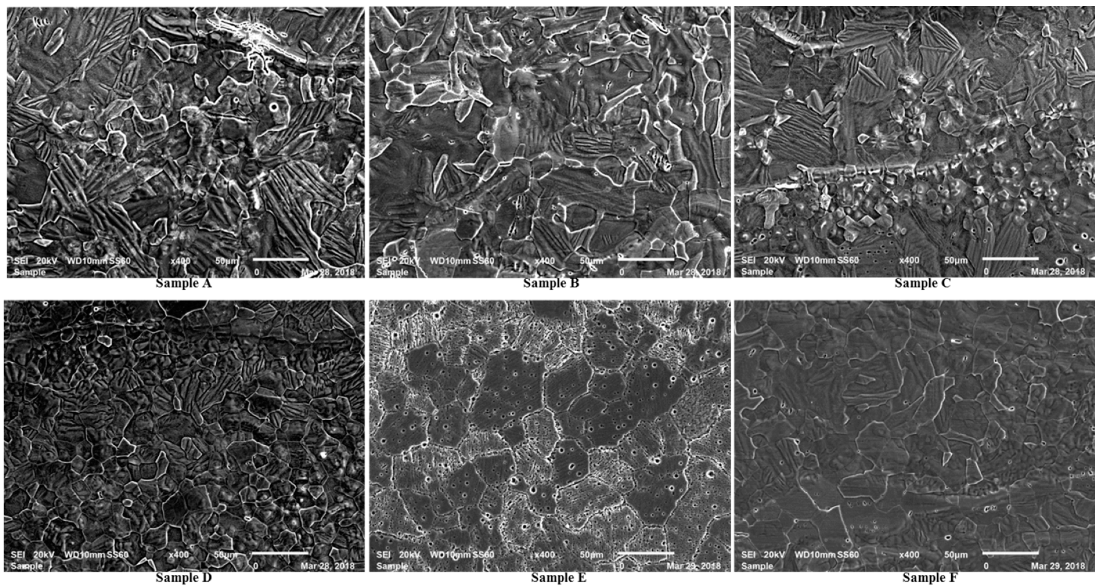
3.3. Heat Treated Samples

Effects of heat treatment on the resulting microstructures of Ti–Al alloys in the duplex and gamma-phase alloys are extensively reported in the literature [1,4,6,10,17,30]. This section reports on the microstructures of Ti–Al alloys (across the Al content spectrum) after heat treatment at 1200 °C and cooling inside the oven.

3.4. Chemical Composition and Microstructures
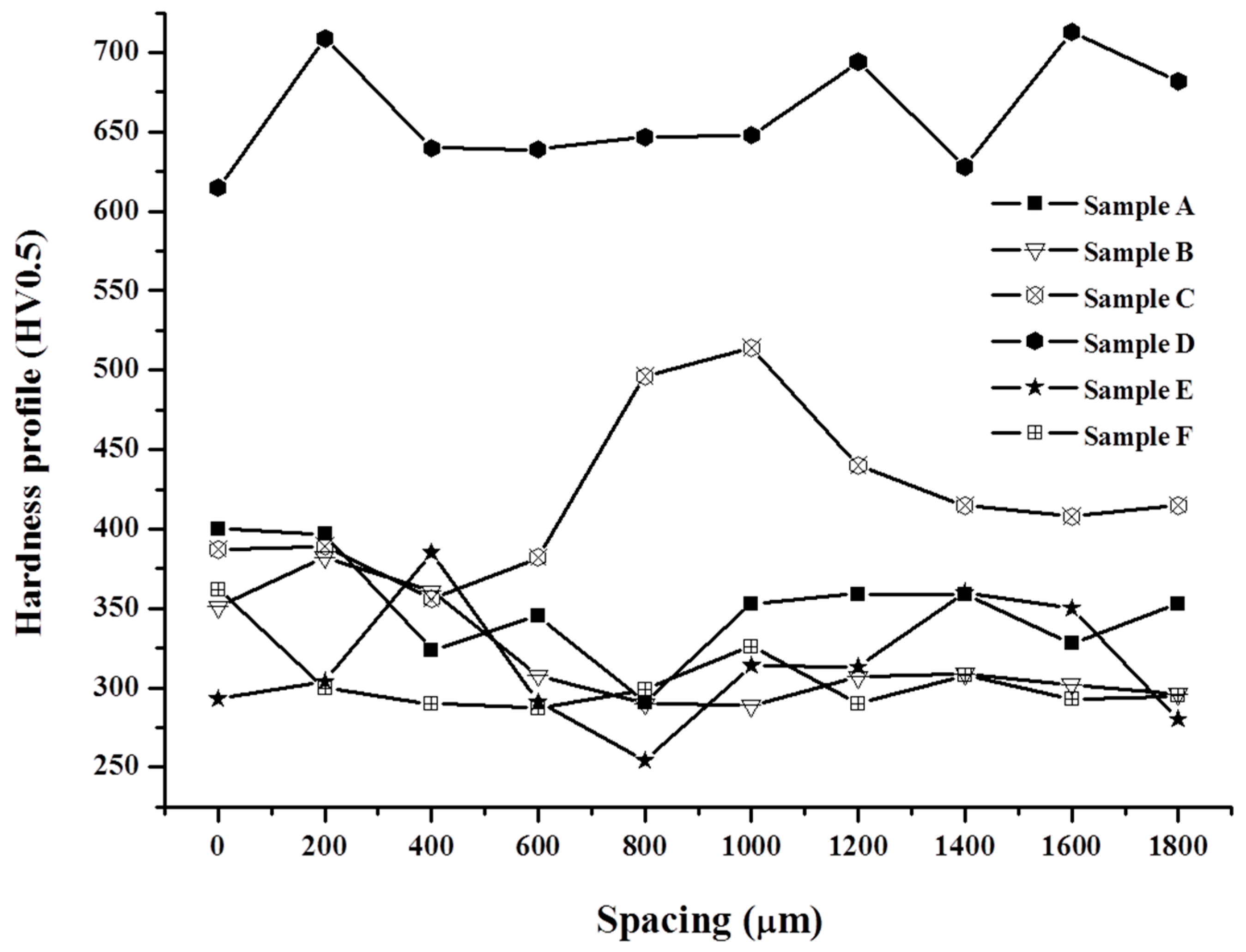
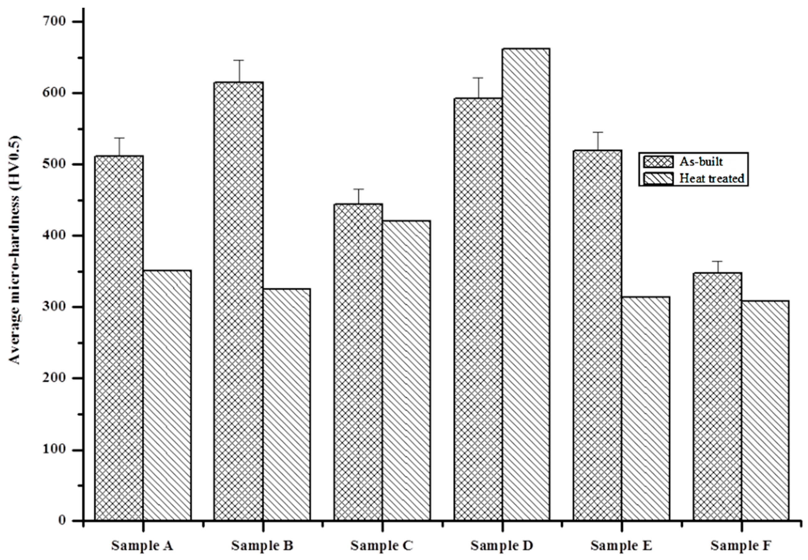
It was observed that post-heat treatment samples B and E had a duplex microstructure with Al contents of 57 and 54 at.%, respectively, while sample A was nearly lamellar, with an Al content of about 53 at.% and sample C had a fully lamellar microstructure with an Al content of 49 at.%. The white spots observed on sample A were aluminium oxide (Al2O3) ,with the bright white phase on the microstructures rich in Al. The black grains that resemble fractures in almost all samples, particularly samples B and E, were rich in Ti. These results are summarized in Figure 8.
Summarizing the results of the as-built and heat treated samples, it can be said that the Al content increased drastically in the heat-treated samples and the microstructures of sample F (duplex) and sample A (nearly lamellar) were the same before and after heat treatment. Sample E transformed from near-gamma to duplex, sample B from nearly lamellar to duplex, sample C from nearly lamellar to duplex, and sample D from duplex to nearly lamellar. In this regard, only sample D performed better in its as-built state, while samples B, E, and F exhibited their best engineering properties post-heat treatment, given that they all had a duplex microstructure. The overall hardness results of these alloys (before and after heat treatment) are reported next.

3.5. Micro-Hardness

Hardness measurements can be used to determine certain mechanical properties of the alloy. For instance, the general relationship between strength and hardness has been studied before [11]. The hardness profiles of Ti–Al alloys before heat treatment are typically wavy and this is, in general, attributed to the heterogeneity and phase precipitates of the build [30]. Heat treatment is supposed to give a homogenized structure, leading to a “smooth” hardness profile of the build. The hardness profiles of the heat-treated samples are reported in Figure 9, while Figure 10 (bar-diagram) compares the overall hardness of the samples before and after heat treatment. In addition, it has been reported that the (α2) phase is harder than the γ phase and that a two-phase (α-Ti+α2-Ti3Al) alloy is harder than pure Ti. The latter is attributed to the precipitation ability of the α2-Ti3Al in the two-phase and the solid solution strengthening of Al [30,38]. It is anticipated that the overall hardness of these alloys should be different, but similar for the alloys with same Al content. Therefore, samples A and D and samples B and F would have similar overall hardness values, respectively. Overall, we anticipated that sample E would be the least hard, followed by sample C, then samples B and F, and finally samples A and D. However, it must be noted that, in addition to the resulting microstructure and phase, the hardness profiles of the samples are affected by other factors, such as material segregation, phase precipitation, and grain-size. The hardness profile is reported in Figure 9.
Hardness curves reported in Figure 9 conclude that Sample D was hardest with fewer points rising above the homogeneity line, which can be imagined to be around 620 HV. Similar observations can be made for sample C, which was also hard. Samples A and E were wavy, while samples B and F were stable. These two samples can be interpreted as homogeneous. The overall hardness values (HV) for the samples after heat treatment were 351 ± 25.6, 325 ± 30.75, 420 ± 22.2, 662 ± 29.6, 314 ± 25.95, and 308 ± 17.35 for samples A–F. These hardness values were compared to the as-built samples as shown in Figure 10 (bar-diagram).
Figure 10 indicates clearly that only the hardness value of sample D increased with heat treatment. Meanwhile, the hardness values of samples B, E, and F decreased to an equivalent value. This is acceptable since these alloys have the same microstructure (duplex) post-heat treatment. More importantly, the hardness value of sample B decreased to almost half after heat treatment, while sample C’s hardness did not significantly change. The observation of hardness across the samples support the findings of Guo et al. [30], who reviewed that the Ti3Al (α2) phase is harder than the TiAl (γ) phase. The pure γ phase samples (samples A, B, E, and F) reported less hardness when compared to sample C, which was dual phase (α2 + γ). It is the presence of the α2 phase that might be contributing to the observed increase in hardness. This observation is contradicted only by sample D, which had the most hardness after heat treatment. This contradiction might be sustained by observations that two-phase (α-Ti + α2-Ti3Al) is harder than γ and pure Ti. It could be that during heat treatment the samples experienced effective Al solid solution strengthening and precipitation of the α2-phase, hence it was the hardest. This study overall corroborates observations made by Guo et al. [30]. This is sustained by sample F (pure Ti) and sample D (α + α2) before heat treatment. Overall, Figure 10 concludes that an alloy with a duplex microstructure will be the least hard, followed by nearly lamellar and then fully lamellar microstructures. This observation holds only when sample D is accepted as an outlier or ambiguous.

4. Conclusions

In this paper, in-situ laser alloying of Ti and Al into a binary Ti–Al was studied. The effects of increasing the Al content and heat treatment on the resulting microstructure and hardness of binary Ti–Al are reported. The results show that, by keeping the laser power and titanium flow-rate constant while increasing the Al content via rpm, different microstructures can be produced in accordance with the binary Ti–Al alloy phase diagram. The as-built samples were found to be harder, in general, than the heat-treated (1200 °C) samples. This is attributed to the difference in the resulting microstructures before and after heat treatment. This study also showed that Al content in the builds did not increase linearly with the increase in rpm as expected. Due to this observation, the hardness of the as-built samples also did not linearly decrease as expected. Post-heat treatment, the hardness of the samples decreased with the increase in Al content, except for one sample which was thought to either be an outlier or that there was precipitation of α2 and solid solution strengthening that occurred during heat treatment.

5. Future Work

In future studies, we would look into the effects of niobium on these binary alloys. Niobium is a ternary alloying element that is able to improve the oxidation and creep resistance of titanium aluminides (Kothari et al., 2012). The results should be interesting, particularly for sample A, which showed signs of oxidation post-heat treatment. EDS analyses clearly resolved that the Al2O3 phase/layer formed during heat treatment. Before this future study is carried out, we will look at the effects of increased Al content via rpm on the overall Al content in the builds. This will help in addressing the observations made in this study and charter a way forward for our future studies.

Author Contributions

M.T. contributed by doing the experiments, results interpretation and write-up while S.P. assisted by interpreting the data and review of this manuscript.

Funding

This research was funded by the Council for Scientific and Industrial Research (CSIR) and National Research Foundation (NRF).

Acknowledgements

Our gratitude is towards The National Research Foundation (NRF) and Council for Scientific and Industrial Research (CSIR). The following grants supported this research: (1) National Research Foundation Thuthuka Research Grant (BM_TTK170905261706); (2) CSIR Young Researcher Establishment Funds (YREF212); (3) CSIR Thematic Grant (LMTRAMC). We like to thank Bathusile Masina, Thabo Lengopeng, Oscar Sono, Samuel Skhosane, Peter Lamola, Nana Arthur (The LENS TEAM) for their support.

Conflicts of Interest

The authors declare no conflict of interest.

References

  1. Wang, G.; Dahms, M. Synthesizing gamma-TiAl alloys by reactive powder processing. JOM 1993, 45, 52–56. [Google Scholar] [CrossRef]
  2. Ma, Y.; Cuiuri, D.; Hoye, N.; Li, H.; Pan, Z. Characterization of in-situ alloyed and additively manufactured titanium aluminides. Metall. Mater. Trans. B 2014, 45B, 2299–2303. [Google Scholar] [CrossRef]
  3. Balla, V.K.; Das, M.; Mohammad, A.; Al-Ahmari, A.M. Additive manufacturing of γ-TiAl: Processing, Microstructure, and Properties. Adv. Energy Mater. 2016, 18, 1208–1215. [Google Scholar] [CrossRef]
  4. Rittingshaus, S.-K.; Hecht, U.; Werner, V.; Weisheit, A. Heat treatment of laser metal deposited TiAl TNM alloy. Intermetallics 2018, 95, 94–101. [Google Scholar] [CrossRef]
  5. Wang, G.-X.; Bartels, A.; Dahms, M. Influence of heat treatment on microstructure and deformation behaviour of the Alloy Ti50Al48Cr2 prepared by reactive powder processing. Mater. Trans. JIM 1993, 34, 228–235. [Google Scholar]
  6. Appel, F.; Clemens, H.; Fischer, F.D. Modeling concepts for intermetallic titanium aluminides. Prog. Mater. Sci. 2016, 81, 55–124. [Google Scholar] [CrossRef]
  7. Appel, F.; Oehring, M.; Paul, J.D.H. A novel in situ composite structure in TiAl alloys. Mater. Sci. Eng. A 2008, 493, 232–236. [Google Scholar] [CrossRef]
  8. Rostamian, A.; Jacot, A. A numerical model for the description of the lamellar and massive phase transformations in TiAl alloys. Intermetallics 2008, 16, 1227–1236. [Google Scholar] [CrossRef] [Green Version]
  9. Brueckner, F.; Seidel, A.; Straubel, A.; Willner, R.; Leyens, C.; Beyer, E. Laser-based manufacturing of components of components using materials with high cracking susceptibility. J. Laser Appl. 2016, 28, 1–7. [Google Scholar] [CrossRef]
  10. Kothari, K.; Radhakrishnan, R.; Wereley, N.M. Advances in gamma titanium aluminides and their manufacturing techniques. Prog. Aerosp. Sci. 2012, 55, 1–16. [Google Scholar] [CrossRef]
  11. Tlotleng, M. Microstructural properties of heat-treated LENS in situ additively manufactured titanium aluminide. J. Mater. Eng. Perform. 2019, 28, 701–708. [Google Scholar] [CrossRef]
  12. Nochovnaya, N.A.; Panin, P.V.; Kochetkov, A.S.; Bokov, K.A. Modern refractory alloys based on titanium gamma-aluminide: Prospects of development and application. Met. Sci. Heat Treat. 2014, 56, 23–27. [Google Scholar] [CrossRef]
  13. Clemens, A.; Bartels, A.; Bystrzanowski, S.; Chladil, H.; Leitner, H.; Dehm, G.; Gerling, R.; Schimansky, F.P. Grain refinement in γ-TiAl based alloys by solid state phase transformations. Intermetallics 2006, 14, 1380–1385. [Google Scholar] [CrossRef]
  14. Wang, Y.H.; Lin, J.P.; He, Y.H.; Lu, X.; Wang, Y.L.; Chen, G.L. Microstructure and mechanical properties of high Nb containing TiAl alloys by reactive hot pressing. J. Alloys Compd. 2008, 461, 367–372. [Google Scholar] [CrossRef]
  15. Couturier, R.; Escaravage, C. High temperature alloys for the HTGR gas turbine: Required properties and development needs; International Atomic Energy Agency: Vienna, Austria, 2001; pp. 163–176. ISSN 1011-4289. [Google Scholar]
  16. Shishkovsky, I.; Missemer, F.; Smurov, I. Direct metal deposition of functional graded structures in Ti-Al system. Physics Procedia 2012, 39, 382–391. [Google Scholar] [CrossRef]
  17. Gasper, A.N.D.; Smith, C.-S.; Clare, A.T. In-situ synthesis of titanium aluminides by direct metal deposition. J. Mater. Sci. Technol. 2017, 239, 230–239. [Google Scholar] [CrossRef]
  18. Yin, S.; Yan, X.; Chen, C.; Jenkins, R.; Liu, M.; Lupoi, R. Hybrid additive manufacturing of Al-Ti6Al-4V functional graded materials with selective laser melting and cold spraying. J. Mater. Process. Technol. 2018, 255, 650–655. [Google Scholar] [CrossRef]
  19. Mumtaz, K.A.; Hopkins, N. Laser melting functionally graded composition of Waspaloy® and Zirconia powders. J. Mater. Sci. 2007, 42, 7647–7656. [Google Scholar] [CrossRef]
  20. Sharman, A.R.C.; Hughes, J.I.; Ridgway, K. Characterisation of titanium aluminide components manufactured by laser metal deposition. Intermetalllics 2018, 93, 89–92. [Google Scholar] [CrossRef]
  21. Cormier, D.; Harrysson, O.; Mahale, T.; West, H. Freeform fabrication of titanium aluminide via electron beam melting using pre-alloyed and blended powders. Mater. Res. Lett. 2007, 1–4. [Google Scholar]
  22. Murr, L.E.; Gaytan, S.M.; Ceylan, A.; Martinez, E.; Martinez, J.L.; Hernandez, D.H.; Machado, B.I.; Ramirez, D.A.; Medina, F.; Collins, S.; et al. Characterization of titanium aluminide alloy components fabricated by additive manufacturing using electron beam melting. Acta Mater. 2010, 58, 1887–1894. [Google Scholar] [CrossRef]
  23. Schwerdtfeger, J.; Körner, C. Selective electron beam melting of Ti-48Al-2Nb-2Cr: Microstructure and aluminium loss. Intermetallics 2014, 49, 29–35. [Google Scholar] [CrossRef]
  24. Tang, H.P.; Yang, G.Y.; Jia, W.P.; He, W.W.; Lu, S.L.; Qian, M. Additive manufacturing of a high niobium-containing titanium aluminide alloy by selective electron beam melting. Mater. Sci. Eng. A 2015, 636, 103–107. [Google Scholar] [CrossRef]
  25. Todai, M.; Nakano, T.; Liu, T.; Yasuda, Y.H.; Hagihara, K.; Cho, K.; Ueda, M.; Takeyama, M. Effect of building direction on the microstructure and tensile properties of Ti-48Al-2Cr-2Nb alloy additively manufactured by electron beam melting. Addit. Manuf. 2017, 13, 61–70. [Google Scholar] [CrossRef]
  26. Löber, L.; Schimansky, F.P.; Kühn, U.; Pyczak, F.; Eckert, J. Selective laser melting of a beta-solidifying TNM-B1 titanium aluminide alloy. J. Mater. Process. Technol. 2014, 214, 1852–1860. [Google Scholar] [CrossRef] [Green Version]
  27. Gussone, J.; Hagedorn, Y.-C.; Gherekhloo, H.; Kasperovich, G.; Merzouk, T.; Hausmann, J. Microstructure of γ-titanium aluminide processed by selective laser melting at elevated temperatures. Intermetallics 2015, 66, 133–140. [Google Scholar] [CrossRef]
  28. Kenel, C.; Dasargyri, G.; Bauer, T.; Collela, A.; Spierings, A.B.; Leinenbach, C.; Wegener, K. Selective laser melting of an oxide dispersion strengthened (ODS) γ-TiAl alloy towards production of complex structures. Mater. Des. 2017, 134, 81–90. [Google Scholar] [CrossRef]
  29. Qu, H.P.; Wang, H.M. Microstructure and mechanical properties of laser melting deposition γ-TiAl intermetallic alloys. Mater. Sci. Eng. A 2007, 466, 187–194. [Google Scholar] [CrossRef]
  30. Guo, B.; Zhou, J.; Zhang, S.; Zhou, H.; Pu, Y.; Chen, J. Phase composition and tribological properties of Ti-Al coatings produced on pure Ti by laser cladding. Appl. Surf. Sci. 2007, 253, 9301–9310. [Google Scholar] [CrossRef]
  31. Qu, H.P.; Li, P.; Zhang, S.Q.; Li, A.; Wang, H.M. The effects of heat treatment on the microstructure and mechanical property of laser melting deposition γ-TiAl intermetallic alloys. Mater. Des. 2010, 31, 2201–2210. [Google Scholar] [CrossRef]
  32. Ma, Y.; Cuiuri, D.; Li, H.; Pan, Z.; Shen, C. The effect of postproduction heat treatment on γ-TiAl alloys produced by the GTAW-based additive manufacturing process. Mater. Sci. Eng. A 2016, 657, 86–95. [Google Scholar] [CrossRef]
  33. Thomas, M.; Malot, T.; Aubry, P. Laser metal deposition of the intermetallic TiAl alloy. Metall. Mater. Trans. A 2017, 48A, 3143–3157. [Google Scholar] [CrossRef]
  34. Maliutina, I.N.; Si-Mohand, H.; Sijobert, J.; Bertrand, P.; Lazurenko, D.V.; Bataev, I.A. Structure and oxidation behavior of γ-TiAl coating produced by laser cladding on titanium alloy. Surf. Coat. Technol. 2017, 319, 136–144. [Google Scholar] [CrossRef]
  35. Zhang, F.; Yang, M.; Clare, A.T.; Lin, X.; Tan, H.; Chen, Y. Microstructure and mechanical properties of Ti-2Al alloyed with Mo formed in laser additive manufacturing. J. Alloys Compd. 2017, 727, 821–831. [Google Scholar] [CrossRef]
  36. Ma, Y.; Cuiuri, D.; Shen, C.; Li, H.; Pan, Z. Effect of interpass temperature on in-ng alloying and additive manufacturing of titanium aluminides using gas tungsten arc welding. Addit. Manuf. 2015, 8, 71–77. [Google Scholar] [CrossRef]
  37. Voisin, T.; Monchoux, J.-P.; Perrut, M.; Couret, A. Obtained of a fine near-lamellar microstructure in TiAl alloys by spark plasma sintering. Intermetallics 2016, 71, 88–97. [Google Scholar] [CrossRef]
  38. Dilip, J.J.S.; Miyanaji, H.; Lassell, A.; Starr, T.L.; Stucker, B. A novel method to fabricate TiAl intermetallic alloy 3D parts using additive manufacturing. Defence Technol. 2017, 13, 72–76. [Google Scholar] [CrossRef] [Green Version]
  39. Tlotleng, M.; Masina, B.; Pityana, S. Characteristics of laser in-situ alloyed titanium aluminides coatings. Procedia Manuf. 2017, 7, 39–45. [Google Scholar] [CrossRef]
  40. Hoosain, S.E.; Pityana, S.; Freemantle, C.S.; Tlotleng, M. Heat treatment of In situ laser-fabricated titanium aluminide. Metals 2018, 8, 655. [Google Scholar] [CrossRef]
  41. Liu, Z.C.; Lin, J.P.; Li, S.J.; Chen, G.L. Effects of Nb and Al on the microstructures and mechanical properties of high Nb containing TiAl base alloys. Intermetallics 2002, 10, 653–659. [Google Scholar] [CrossRef]
Figure 1. Schematic representation of the Laser Engineered Net Shaping (LENS) set-up.
Metals 09 00623 g001
Figure 2. Ti–Al phase diagram. Reproduced from [10], with permission from Elsevier, 2012.
Metals 09 00623 g002
Figure 3. LENS in situ printed Ti–Al cubes.
Metals 09 00623 g003
Figure 4. Surface cracks and different textures.
Metals 09 00623 g004
Figure 5. Al content [EDS vs. set rpm].
Metals 09 00623 g005
Figure 6. Microstructures of the Ti–Al as-built samples.
Metals 09 00623 g006
Figure 7. High magnification images of the as-built samples.
Metals 09 00623 g007
Figure 8. Microstructures of the alloys after heat treatment.
Metals 09 00623 g008
Figure 9. Hardness profile of the heat-treated samples.
Metals 09 00623 g009
Figure 10. Overall hardness of the alloys compared.
Metals 09 00623 g010
Table 1. Aluminum mass flow rates.
Sample IDSet Value (rpm)Al Mass Flowrate (g/min)
Sample A1.00.11
Sample B1.20.14
Sample C1.40.17
Sample D1.60.20
Sample E1.80.26
Sample F2.00.33
Table 2. Process parameters that were used.
ParameterSymbolSet-ValueUnit
Laser powerP400W
Laser spot sizeD1.4mm
Focal lengthL144mm
Stand-off distanceSOD8mm
Deposition speedS80%in/mm
Powder flow-rate (Ti)M12rpm
Powder flow-rate (Al)M21-2rpm
Layer thicknessD0.2mm
Hatch spacingW0.66mm
Shielding gas flow-ratef125L/min
Process gas flow-rate (Ti)f24L/min
Process gas flow-rate (Al)f36L/min
Table 3. Chemical composition (at.%) of the as-built samples.
Sample IDTiAlStandard Deviation
Sample A84.2015.80±2.30
Sample B91.018.99±1.75
Sample C75.9424.06±0.16
Sample D84.7415.26±2.36
Sample E44.6255.38±1.52
Sample F90.069.94±1.87

