The Impact of the Gas Inlet Position, Flow Rate, and Strip Velocity on the Temperature Distribution of a Stainless-Steel Strips during the Hardening Process
Abstract
:1. Introduction
2. Experimental Work
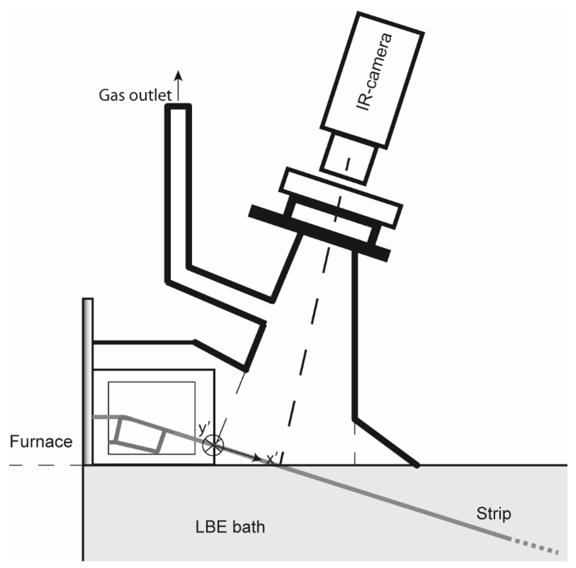
2.1. Plant Trials
2.2. Temperature Measurements
3. Mathematical Model
3.1. Mathematical Formulation
- (a)
- A laminar non-isothermal hydrogen flow was considered in the study (because of Reynolds number, calculated based on the inlet).
- (b)
- Within the hydrogen filled sealed box domain, the laminar Navier–Stokes equation was solved numerically in combination with the energy balance and continuity equation. Thus, within the sealed box a thermal interaction between the hydrogen flow and the strip takes place.
- (c)
- The thermal interaction between the strip and the molten metal bath was investigated by only considering heat conduction.
- (d)
- Steady state was assumed and therefore the transient effects (time dependency) were neglected.
- (e)
- The gravitational force was neglected.
- Continuity equation:where is the mass density (kg/m3) and is the velocity vector (m/s).
- Momentum equation:where is the transpose matrix, is the pressure (Pa), are the dynamic viscosity of the fluid [Pa·s] and stands for the identity matrix.
- Energy balance equation:where, defines the heat capacity at a constant pressure (J/kg·K), represents the thermal conductivity (W/ (m·K)) and is the temperature (K).
3.2. Boundary Conditions and the Initial Values
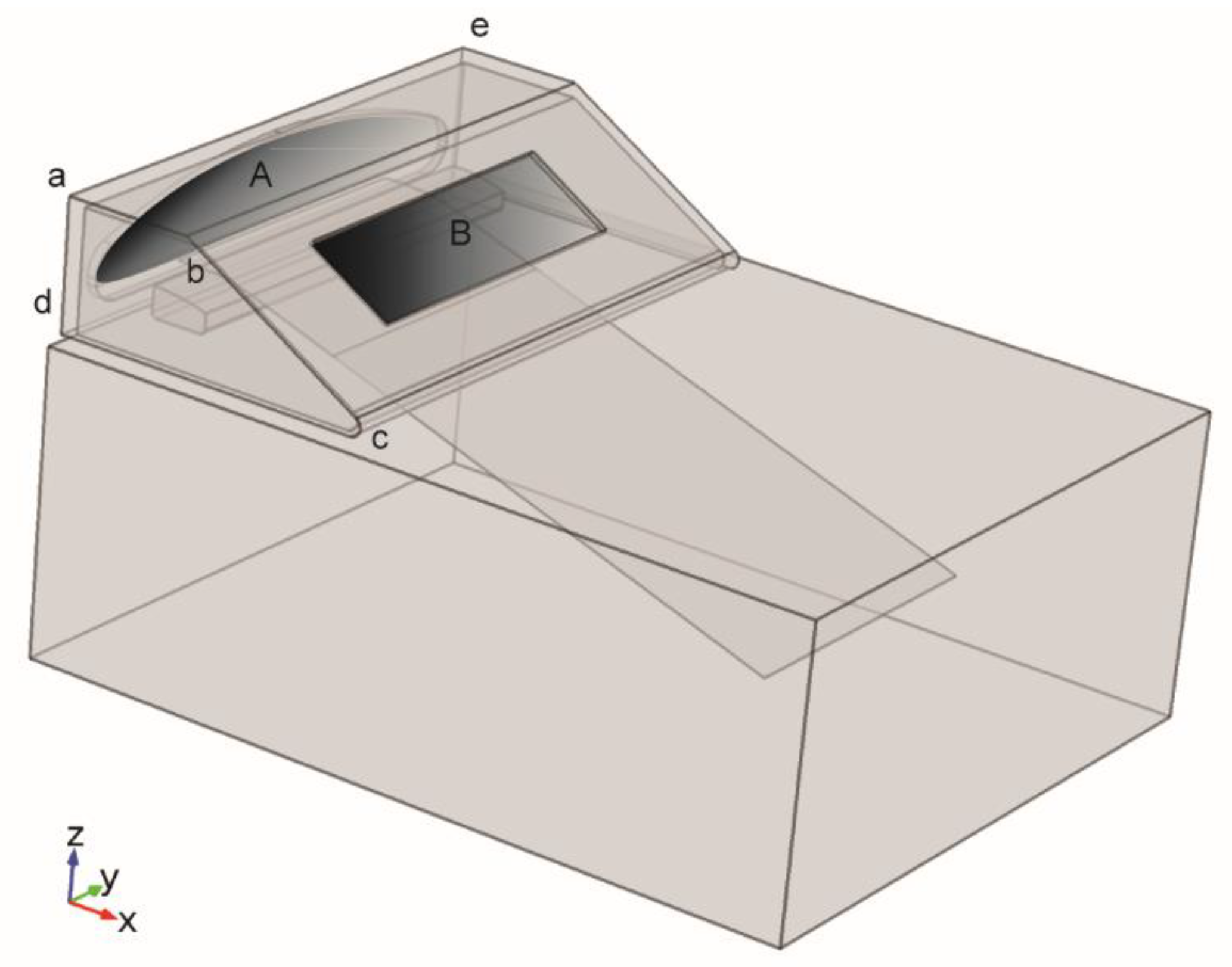
- A no–slip boundary condition for the inner side of the ceiling of the metal box.
- A moving wall for the strip parts located inside the sealed metal box. The value is the same as the velocity of the strip in the process. where is .
- A velocity gas inlet for the surface A in Figure 2 = , Nm3/h, m/s, Moreover, different flow rates for hydrogen gas were investigated numerically in order to determine the impact of this parameter on the predictions. The values Nm3/h, Nm3/h and Nm3/h were assumed in the parametric study.
- A typical furnace temperature for the Surface A and its connected surface. °C.
- A pressure outlet at the Surface B in Figure 2 where a backflow is allowed.
- A convective heat flux for the outside the ceiling part of the sealed box., = 20 °C assumed heat transfer coefficient W·m–2·K–1.
- A surface to surface radiation for the inner side of the ceiling of the gas box, surface of the strip, and the surface of the LBE bath in the sealed metal box. [18].: surface emissivity, : incoming radiative heat flux W·m–2, : Stefan–Boltzmann W·m–2·K–4.
- A typical set point temperature for the bath. °C. Details of the choosing the proper bath boundary condition is described in details in reference [16].
- A convective heat flux for the top surface of the bath, outside area of the sealed metal box.°C, a low value of due to oxidation, W·m–2·K–1 is assumed.
3.3. Numerical Conditions
4. Results and Discussion
4.1. The Impact of the Alternative Placement of the Gas Inlet
4.1.1. Grid Sensitivity Study
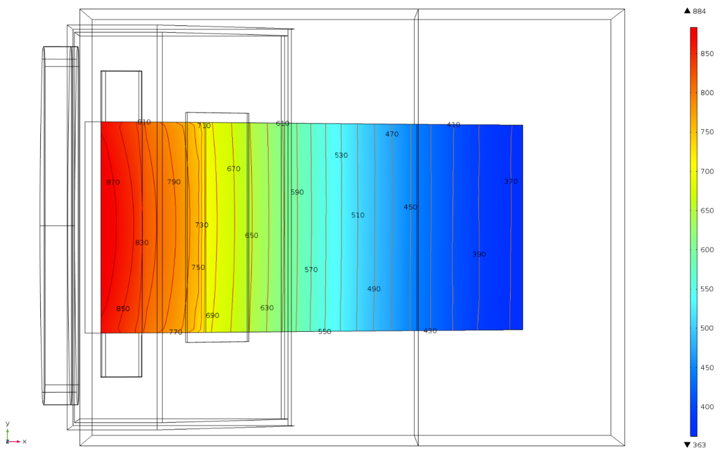
4.1.2. Numerical Model Predictions
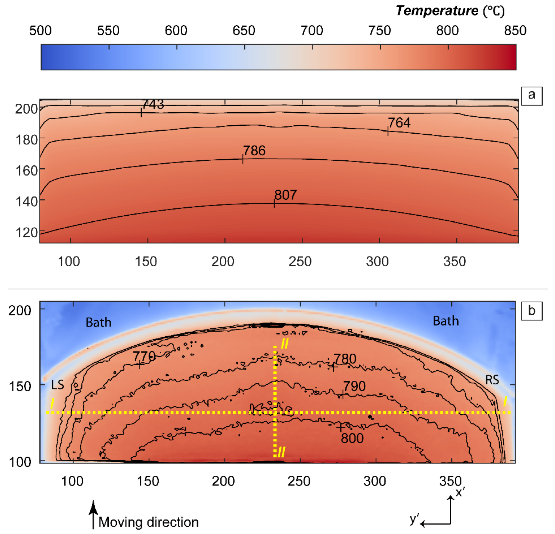
4.1.3. Validation of the Model
4.1.4. Comparison between Two Gas Inlet Positions
4.2. The Impact of the Different Hydrogen Flow Rate
4.3. The Impact of the Different Strip Velocity
5. Conclusions
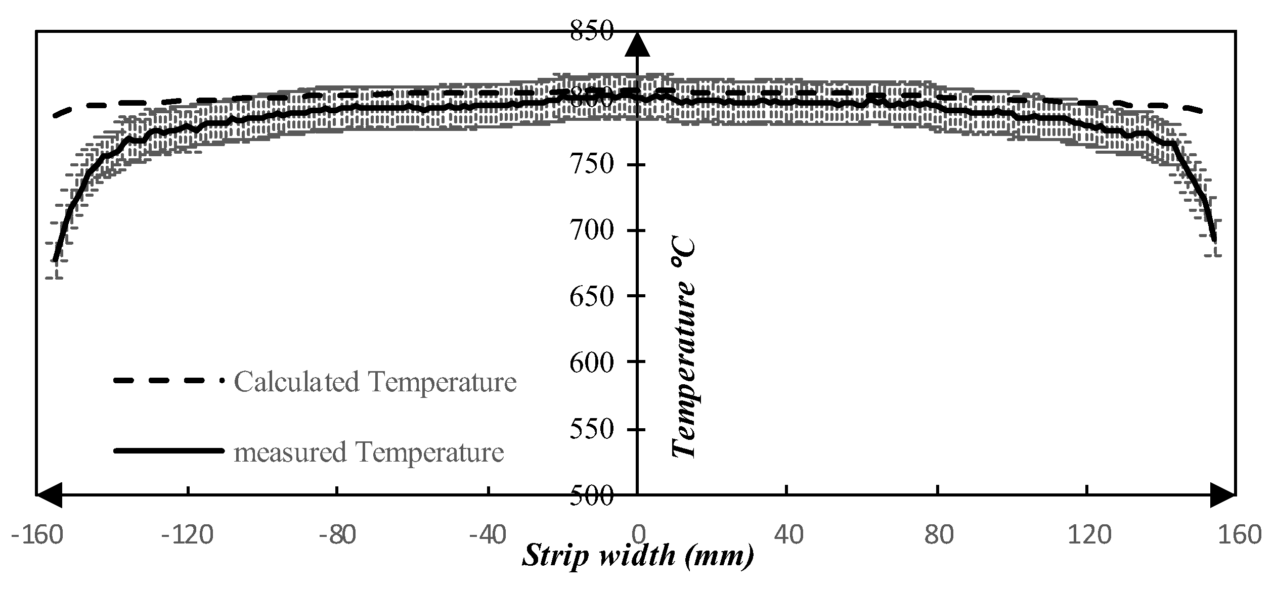
- By using an alternate gas inlet and position, where the main gas flow is in the same direction as the strip as opposed to a crossflow scenario, a significant higher degree of symmetry with respect to temperature is achieved along the transverse direction (width of strip). Specifically, the difference of the temperature in the transverse direction (width of strip) decreased by 9% and 14% based on the calculated temperature and measured values, respectively.
- Increasing the hydrogen flow rate, a reduction of the temperature difference across the transversal direction, close to the bath interface is observed. Specifically, by increasing the flow rate by 2 Nm3/h, the transverse temperature difference decreased by approximately 20%. Thus, a higher gas flow rate promotes a smaller temperature difference along the width of the strip.
- A parametric study of the strip velocity showed that by increasing the velocity of the strip in the process by 2 m/min, the maximum temperature at close to the bath interface increases marginally. Thus, the effect of the strip velocity on the strip temperature is quite small.
Author Contributions
Acknowledgments
Conflicts of Interest
References
- Webster, H.; Laird, W.J. Martempering of Steel, Heat Treating. In ASM Handbook; ASM International: Materials Park, OH, USA, 1991; Volume 4, pp. 137–151. [Google Scholar]
- Ebner, J. Bright Heat Treating of Carbon Steel Strip Using a Lead Quench. Mach. Steel Austria 1983, 4, 83–90. [Google Scholar]
- Lochner, H. Hardening of strip in a molten-metal bath or hydrogen jet cooler. Steel Times 1994, 222, 350. [Google Scholar]
- Lochner, H. Steel strip hardening and tempering lines for medium and high carbon steels and alloyed grades part I: Production lines with liquid metal quenching. In Proceedings of the IFHTSE—International Federation for Heat Treatment and Surface Engineering, Vienna, Austria, 25–29 September 2006; p. 43. [Google Scholar]
- Thelning, K.-E. 7-Dimensional changes during hardening and tempering. In Steel and its Heat Treatment, 2nd ed.; Butterworth-Heinemann: Oxford, UK, 1984; p. 581. [Google Scholar]
- Yoshida, H. Analysis of Flatness of Hot Rolled Steel Strip after Cooling. Trans. Iron Steel Inst. Jpn. 1984, 24, 212–220. [Google Scholar] [CrossRef]
- Wang, S.-C.; Chiu, F.-J.; Ho, T.-Y. Characteristics and prevention of thermomechanical controlled process plate deflection resulting from uneven cooling. Mater. Sci. and Technol. 1996, 12, 64–71. [Google Scholar] [CrossRef]
- Wang, X.; Yang, Q.; He, A. Calculation of thermal stress affecting strip flatness change during run-out table cooling in hot steel strip rolling. J. Mater. Proc. Technol. 2008, 207, 130–146. [Google Scholar] [CrossRef]
- Wang, X.; Li, F.; Yang, Q.; He, A. FEM analysis for residual stress prediction in hot rolled steel strip during the run-out table cooling. App. Math. Model. 2013, 37, 586. [Google Scholar] [CrossRef]
- Guarino, S.; Barletta, M.; Afilal, A. High Power Diode Laser (HPDL) surface hardening of low carbon steel: Fatigue life improvement analysis. J. Manufac. Proc. 2017, 28, 266–271. [Google Scholar] [CrossRef]
- Idan, A.F.І.; Akimov, O.; Golovko, L.; Goncharuk, O.; Kostyk, K. The study of the influence of laser hardening conditions on the change in properties of steels. East Eur. J. Adv. Technol. 2016, 2, 5. [Google Scholar] [CrossRef]
- Rappaz, M. Modelling of microstructure formation in solidification processes. Int. Mater. Rev. 1989, 34, 93–124. [Google Scholar] [CrossRef]
- Choudhary, S.K.; Mazumdar, D.; Ghosh, A. Mathematical Modelling of Heat Transfer Phenomena in Continuous Casting of Steel. ISIJ International 1993, 33, 764–774. [Google Scholar] [CrossRef]
- Koric, S.; Hibbeler, L.C.; Liu, R.; Thomas, B.G. Multiphysics Model of Metal Solidification on the Continuum Level. Numer. Heat Transf. Part B Fundam. 2010, 58, 371–392. [Google Scholar] [CrossRef]
- Eriksson, S. (R&D Process Technology, Voestalpine Precision Strip AB, Munkfors, Sweden). Personal communication, 2012. [Google Scholar]
- Pirouznia, P.; Andersson, N.Å.I.; Tilliander, A.; Jönsson, P.G. An investigation of the Temperature Distribution of a Thin Steel Strip during the Quenching Step of a Hardening Process. Metals 2019, 9, 675. [Google Scholar] [CrossRef]
- DIAS Infrared Systems. Available online: http://www.webcitation.org/785ncpRm6 (accessed on 3 May 2019).
- Multiphysics, C. Heat Transfer Module User’s Guide; Version 5.1; COMSOL AB: Stockholm, Sweden, 2015. [Google Scholar]
- COMSOL. COMSOL Multiphysics v.5.1. Available online: https://www.comsol.se/release/5.1 (accessed on 3 May 2019).
- Minkina, W.; Dudzik, S. Errors of Measurements in Infrared Thermography. In Infrared Thermography; John Wiley & Sons, Ltd.: Hoboken, NJ, USA, 2009; p. 61. [Google Scholar]





| A (mm2) | B (mm2) | ||||||
|---|---|---|---|---|---|---|---|
| 129.8 | 222.6 | 317.6 | 130.0 | 585.0 | 31,780 | 334 × 102 | 10 |
| Location of Gas Inlet | ||||
|---|---|---|---|---|
| Calculated Temperature Figure 11a | Alternative location (Figure 10b) | 805 | 795 | 10 |
| Side of gas box [16] (Figure 10a) | 781 | 770 | 11 | |
| Measured Temperature Figure 11b | Alternative location (Figure 10b) | 802 | 767 | 35 |
| Side of gas box [16] (Figure 10a) | 784 | 743 | 41 |
| Volumetric Flow Rate (Nm3/h) | °C | ||
|---|---|---|---|
| 1.66 | 798 | 777 | 21 |
| 2.66 | 805 | 785 | 20 |
| 3.66 | 810 | 792 | 18 |
| 4.66 | 816 | 800 | 16 |
| The Velocity of the Strip (m/s) | |||
|---|---|---|---|
| 804.3 | 785.6 | 18.7 | |
| 804.7 | 785.7 | 18.9 | |
| 805.0 | 785.8 | 19.2 | |
| 805.4 | 785.9 | 19.4 | |
| 805.8 | 786.1 | 19.7 |
© 2019 by the authors. Licensee MDPI, Basel, Switzerland. This article is an open access article distributed under the terms and conditions of the Creative Commons Attribution (CC BY) license (http://creativecommons.org/licenses/by/4.0/).
Share and Cite
Pirouznia, P.; Andersson, N.Å.I.; Tilliander, A.; Jönsson, P.G. The Impact of the Gas Inlet Position, Flow Rate, and Strip Velocity on the Temperature Distribution of a Stainless-Steel Strips during the Hardening Process. Metals 2019, 9, 928. https://doi.org/10.3390/met9090928
Pirouznia P, Andersson NÅI, Tilliander A, Jönsson PG. The Impact of the Gas Inlet Position, Flow Rate, and Strip Velocity on the Temperature Distribution of a Stainless-Steel Strips during the Hardening Process. Metals. 2019; 9(9):928. https://doi.org/10.3390/met9090928
Chicago/Turabian StylePirouznia, Pouyan, Nils Å. I. Andersson, Anders Tilliander, and Pär G. Jönsson. 2019. "The Impact of the Gas Inlet Position, Flow Rate, and Strip Velocity on the Temperature Distribution of a Stainless-Steel Strips during the Hardening Process" Metals 9, no. 9: 928. https://doi.org/10.3390/met9090928
APA StylePirouznia, P., Andersson, N. Å. I., Tilliander, A., & Jönsson, P. G. (2019). The Impact of the Gas Inlet Position, Flow Rate, and Strip Velocity on the Temperature Distribution of a Stainless-Steel Strips during the Hardening Process. Metals, 9(9), 928. https://doi.org/10.3390/met9090928


