Article

Effect of Parameters Change on the Weld Appearance in Stainless Steel Underwater Wet Welding with Flux-Cored Wire

1
State Key Laboratory of Advanced Welding and Joining, Harbin Institute of Technology, Harbin 150000, China
2
Shandong Provincial Key Laboratory of Special Welding Technology, Harbin Institute of Technology at Weihai, Weihai 264209, China
3
Shandong Institute of Shipbuilding Technology, Weihai 264209, China
*
Author to whom correspondence should be addressed.
Metals 2019, 9(9), 951; https://doi.org/10.3390/met9090951
Submission received: 1 August 2019 / Revised: 17 August 2019 / Accepted: 23 August 2019 / Published: 30 August 2019

Abstract

:
The underwater wet welding (UWW) technology is rapidly developing as a crucial method in the maintenance work of marine equipment and offshore platform. The rapid development of UWW technology has also exposed the problems to be solved urgently. Therefore, the influence of welding parameters on the weld appearance and welding spatters was investigated in this paper. The main welding parameters used in the study are welding current, arc voltage, welding speed and the contact tip-to-work distance (CTWD). Through the orthogonal test, it is found that, as each welding parameter increases within a certain range, the amounts of welding spatter decreases first and then increases, and the weld forming effect first becomes better and then deteriorates. The amount of wet welding spatter is mainly affected by the welding speed. When the welding speed is low, the splash is more, and the change of the welding current and the arc voltage has a little effect on the number of spatters. When the welding speed is large, the spatter is most with a small welding current and a large arc voltage. After evaluating the weld morphology obtained by welding under various parameters, a set of optimal parameters was obtained. The best parameters for the underwater wet welding of stainless steel with self-shielded flux-cored wire are determined to be 200 A-29 V-2.0 mm/s-15 mm (CTWD).

1. Introduction

304 stainless steel is widely used in various offshore engineering platforms due to its excellent corrosion resistance. During the construction and maintenance of these platforms, underwater welding technology is being widely used and rapidly developed [1,2,3]. Underwater welding technology can be roughly divided into three types: dry welding, local cavity welding and wet welding. The underwater wet welding (UWW) is widely used because of simple equipment, the low cost, and the outstanding operability. UWW, in particular, especially underwater wet flux-cored arc welding (FCAW), has rapidly developed in recent years on account of its high efficiency and ease of automation [4,5,6].
In the process of UWW, the arc is not isolated from the water environment. The welding process is greatly affected by water and the weld morphology was extremely deteriorated. Thorny issues, for instance, the drastic and unavoidable cooling effect of water on the arc and the molten pool makes the weld appearance extremely poor with internal and surface defects and a mass of spatters. [7,8]. Zhang et al. considered that the repulsive transition to be the main cause of the uneven weld asymmetry [9]. Jia et al. found that the width of UWW joint is about two-thirds that of welding in air [10]. It is believed that the change in width is due to the shrinking effect of water on the arc. Shi et al. considered that water depth and welding speed have a great influence on UWW weld formation [11].
Fu et al. observed two types of spatters in wet welding, namely local droplet repelled spatter and the droplet explosion spatter [12]. It is believed that the welding spatter form mainly depends on the droplet transfer mode. Molleda et al. considered that the welding spatter is the droplet of metal that the molten pool flies after being impacted [13]. Guo et al. achieved initial control of the wet welding droplet transfer process by using pulse current [14]. Chen et al. observed that the arc bubble in FCAW has an important influence on the mater transfer process. The weld appearance was improved after the stabilizing of metal transfer by limiting the bubble rising through a novel constraint device [15].
In the field of underwater FCAW, although the above research contents can be used for reference, it cannot be fully applied due to the particularity of the underwater wet welding environment described above. Therefore, it is necessary to explore the influence of welding parameters on weld appearance and welding spatter in FCAW, and control weld formation, reduce welding spatter, and establish the optimal welding process parameter window for UWW.
In present study, the influence of parameters i.e., welding current, arc voltage, welding speed and the contact tip-to-work distance (CTWD) on the weld appearance and the mass of spatters was investigated by an orthogonal test with 4 factors and 4 levels. The optimal welding process parameters were obtained.

2. Materials and Methods
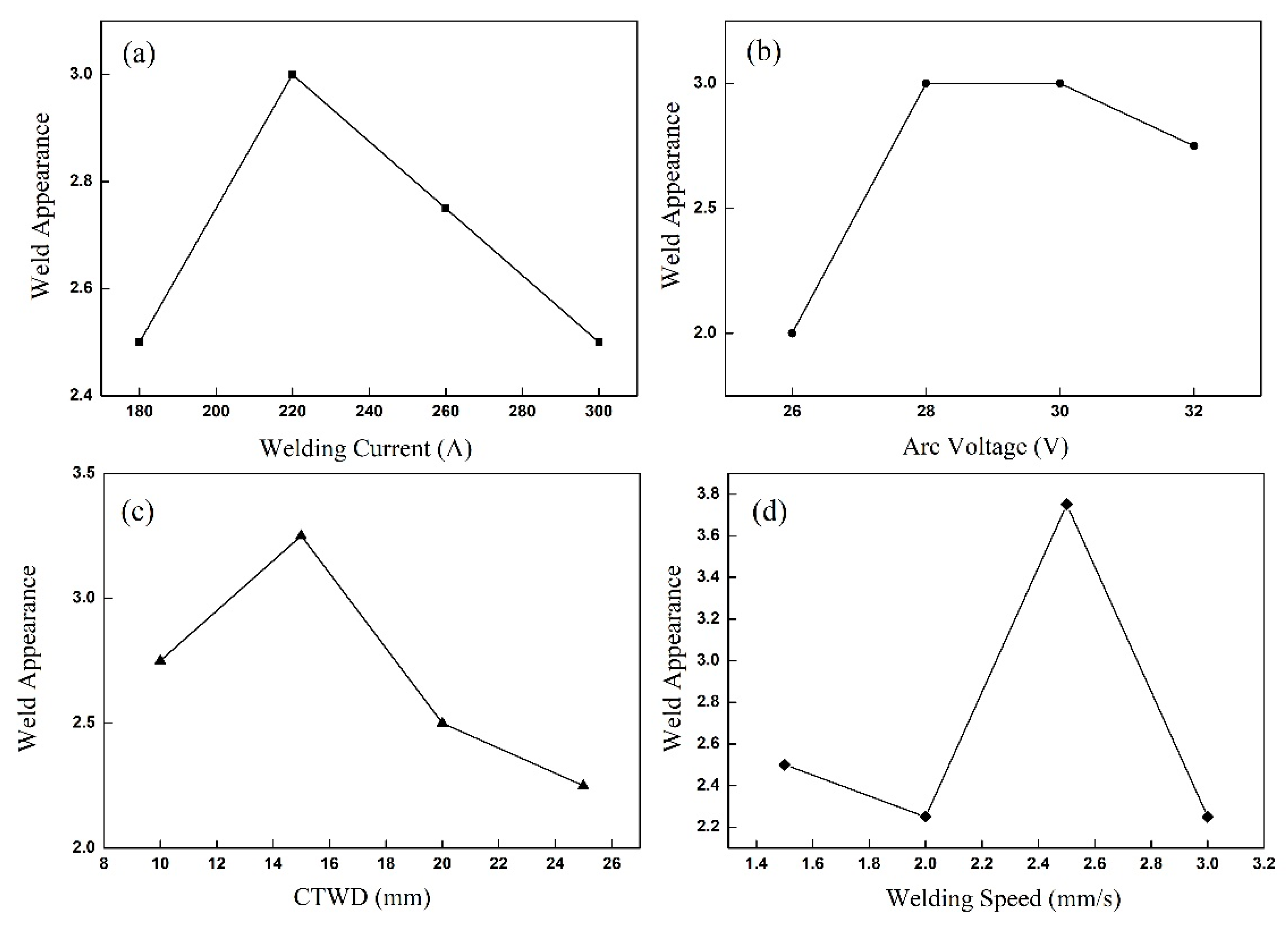
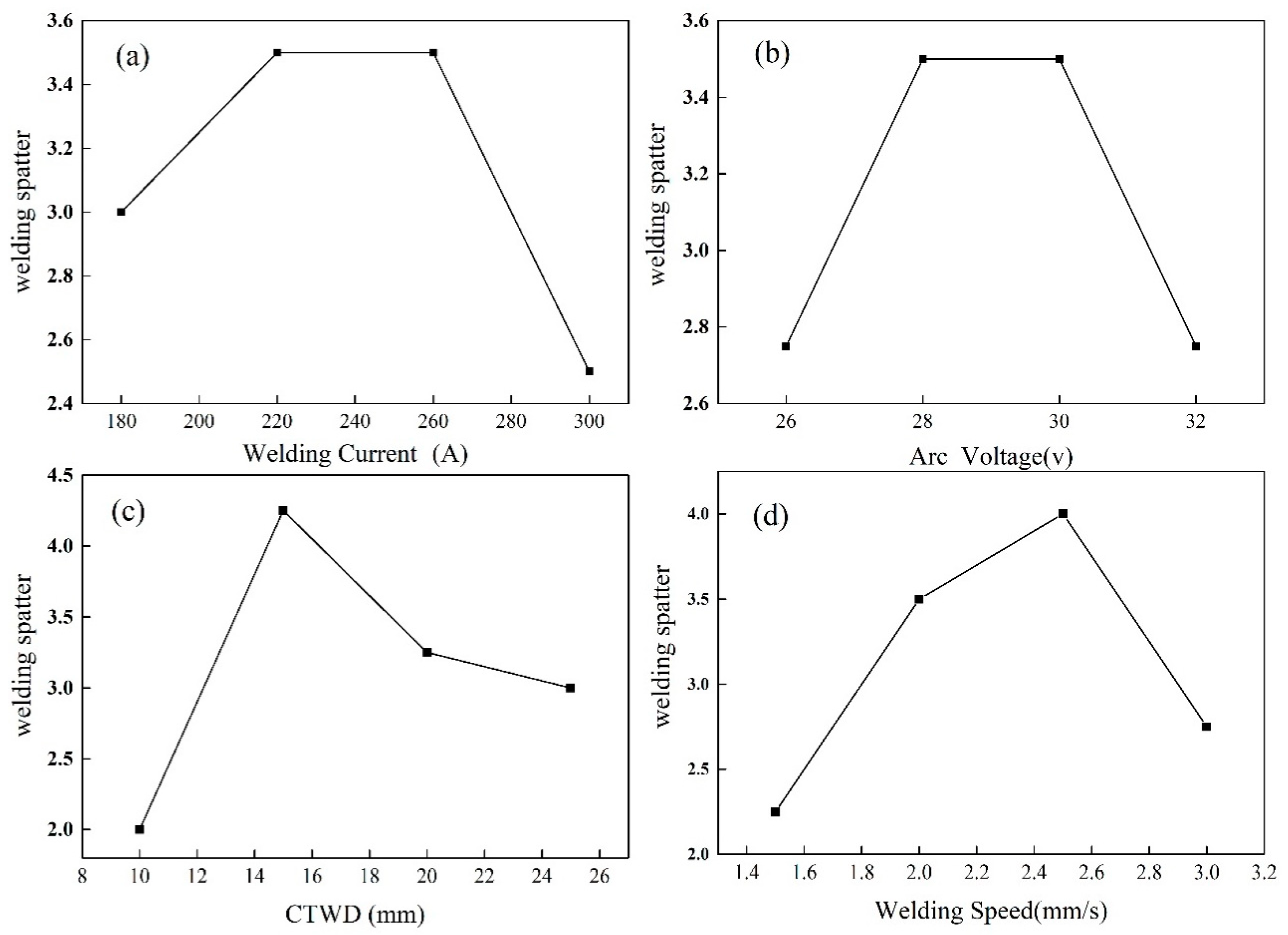
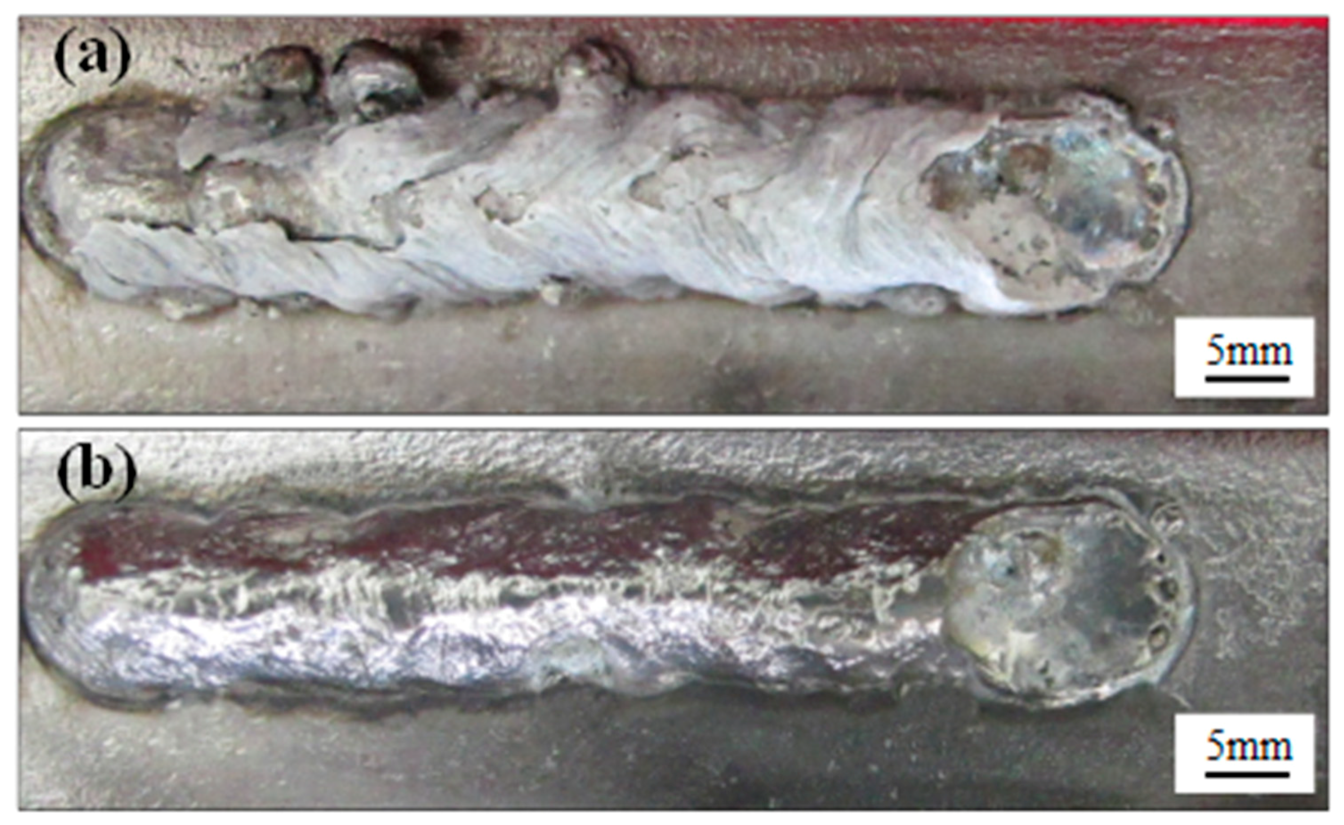
The welding base material selected in this test was 304 stainless steel, the main element content (except Fe element) and mechanical properties are shown in Table 1 and Table 2.
The filler material of this test is self-developed flux cored wire for stainless steel underwater FCAW. The resulting flux-cored wire has a diameter of 1.6 mm. The outer metal is pure nickel (nickel content ≥ 99.9%), the width of the nickel strip is 12 mm, and the thickness is 0.5 mm. In order to ensure the filling rate of the flux-cored wire is stable, all of the flux-cored wire used in this test was made in Luoyang Shuangrui Special Alloy Material Co., Ltd. (Luoyang, China).
In this test, the UWW test is carried out on the self-built underwater welding automatic control platform. As shown in Figure 1, the control cabinet can manually and automatically control the movement speed, direction and route of the welding torch during the welding process. The torch angle is 90°. The size of the water tank is 700 mm × 450 mm × 350 mm, which can meet the requirements of this test. The welder model is SAF-PRO DiGI@WAVE500, the power supply characteristics are constant pressure type, and it is equipped with automatic wire feeding system, and welding current and wire feeding. The wire-feeding speed is automatically matched. All welding runs in this test were reversed by Direct Current. The workpiece is placed on the platform with a water depth of 0.5 m and welded in water.

3. Results

In the previous research work, a suitable stainless steel wet welding flux-cored wire has been obtained [16]. In order to explore its optimal process parameters, the orthogonal tests were designed with the help of 4 factors and 4 levels as shown in Table 3. In this test, the four factors are current (I), voltage (U), welding speed (V) and the CTWD. On the basis of the preliminary test, the current test range was positioned at 180–300 A, the interval between adjacent levels was 40 A; the voltage range was 26–32 V, the voltage interval between adjacent levels was 2 V; the welding speed range was 1.5–3.0 mm/s, the interval between adjacent levels was 0.5 mm/s; the range of CTWD was 10–25 mm, and the interval between adjacent levels was 5 mm. For the welding quality, macroscopic evaluation was mainly taken from the aspects of weld formation and the amount of welding splashing. The weld obtained by the test were divided into 5 grades according to its weld morphology from excellent to rotten. Grade 1 indicates poor weld formation, as shown in Figure 2a; grade 5 indicates good weld formation, as shown in Figure 2b. Similarly, in the splash rating, a 1 indicates a lot of splashes and a 5 indicates a small amount. This means that the weld appearance becomes better and the amount of spatter was reduced. The specific results in each group are shown in Table 3.
Welding forming is the most intuitive way to measure the welding effect. As shown in Figure 2, the surface of the welded joint was covered with pores and pits, which were not smooth, had no obvious metallic luster, and had a large amount of splash on both sides. In Figure 2b, the weld was basically free of defects such as pores and pits. The surface of the weld in Figure 2b was smooth and had obvious metallic luster, which was an ideal weld. In the weld obtained by the orthogonal test, the weld in Figure 2a was poor, indicated by grade 1, and the weld in Figure 2b was excellent, indicated grade 5. The welds in each of the above groups were evaluated in order, and the results were shown in Table 1. In this way, the influence of each welding parameter on the weld formation was studied.
It can be seen from Figure 3a that, when the current was small, the welding forming was significantly improved as the welding current increased. The main reason is that, when the current was too small, the amount of molten metal was less, which may cause the weld bead to be discontinuous, thereby deteriorating the weld bead formation. When the welding current exceeded 200 A, the weld bead was gradually deteriorated as the current increases. Here were the reasons, as the current increased, the welding heat input increased, and the hydrogen partial pressure on the surface of the molten pool increased with the increase of temperature. This means that the hydrogen content in the molten pool increased as the current. When the molten pool was cooled, the solubility of hydrogen was lowered, and a large amount of gas would begin to overflow, so that the surface of the molten pool was greatly fluctuated. When the surface of the molten pool was solidified, a bump bead was formed. Moreover, the wet welding has a faster cooling rate, and the gas in the molten pool is less than floating and escaping, and pores are left inside and on the surface of the weld, which also deteriorates the surface formation.
It can be seen from Figure 3b that, as the welding voltage increased, the weld appearance was greatly improved when it was raised from 26 to 28 V. When the voltage exceeded 28 V, the forming tended to become stable. After the voltage rose to more than 30 V, the appearance of the welding seam became worse. When the welding voltage was less than 26 V, the width of welding arc was small, and the molten metal was accumulated in a narrow place, which was easily to cause the occurrence of the welding tumor. When the voltage was too large, the arc length was long, which tended to cause the arc stability to decrease, thereby making the weld appearance worse.
The CTWD is mainly composed of two parts: the length of wire extension and the distance from the end of the wire to the workpiece. Since the arc length is proportional to the wire extension, both the wire extension and the arc length increase as the CTWD becomes longer. During the welding process, resistance heat was generated at the position of wire extension, which preheated the wire. When the wire elongation was too short, the wire heated up during the preheating period, resulting in less heat to melt the wire. The slower melting speed tended to cause short circuits frequently, and the explosion caused by the welding short circuit deteriorated the weld bead formation. When the CTWD was too large, the long arc length caused the decrease of arc stability, and the weld formation was also poor. Therefore, as shown in Figure 3c, the most suitable CTWD value was 15 mm.
As shown in Figure 3d, the weld appearance became better first while the welding speed increased. After the welding speed exceeded 2.5 mm/s, the weld appearance deteriorated significantly. This was because, when the welding speed was low, the welding heat input was large, resulting in a large size of the weld pool and the fusion zone, so the reaction time of the molten pool was long. Too much molten metal would accumulate in the molten pool, resulting in a higher residual height, which easily formed defects such as slag inclusions in the weld. When the welding speed was too large, the gas generation becomes unstable and the cooling rate of the molten pool was also accelerated. In this case, the pores in the weld were increased and the surface was covered with pits.
Welding spatter was the particles that fell on the solidified weld seam and the surrounding basic metal during welding. Some of them were the droplets that haven’t transited into the molten pool. During the welding process, the spatter adhered to the workpiece, which was easy to cause corrosion during UWW. Additional labor was necessary to polish the important workpiece [17]. However, the cleaning of welding spatter was also more inefficient and costly to process in water. In addition, the generation of splash would also affect the stability of the welding arc, reducing the welding rate and productivity of the welding. This test was only for qualitative analysis of the influence of welding parameters on the spatter. It adopted the method of visuals according to how much the amount of spatter was divided into five levels, respectively with the Numbers 1, 2, 3, 4, 5, as shown in Table 3.
The influences of welding parameters on welding spatter were obtained, as shown in Figure 4. As can be seen from Figure 4a, when the current was less than 220 V, the spatter amount decreased with the increase of welding current. When the current was too small, the proportion of short circuit transition would increase, and the proportion of short circuit explosion would increase. Therefore, spatter was easy to occur. When the current was too large, the temperature was higher in the welding process, and the vapor pressure generated by evaporation hindered the droplet transition, making the droplet size larger and increasing the possibility of producing large particles to repel spatter. In addition, as the size of the droplets increased, there were much more spatters generated as the droplet falls into the pool.
Arc voltage and CTWD have the same influence on the welding spatter, both of them affect the generation of spatter by affecting the arc length. When the voltage or CTWD was low, the arc was short, and droplet short circuit and solid short circuit transition were easy to occur, which increased the probability of explosive spatter. However, when the voltage increased, the arc length increased. The excessively long arc was unstable, which decreased the stability of the welding process, so that the welding spatter increased. When the welding speed was small, the heat input was large, and the molten pool solidified slowly, so the amount of spatter caused by the molten pool oscillation increased. When the welding speed was too large, the molten pool was located behind the wire. Therefore, the arc force received by the droplet had a large lateral component. The droplet was easy to fly laterally, forming a large droplet splash. Therefore, as shown in Figure 4d, when the welding speed was small, the spatter decreased with the increase of the welding speed, and when the welding speed reached a certain value, the spatter also increased with the increase of the welding speed.
The influence of welding parameters on welding spatter was not independent of a single factor, but rather the mutual influence of various parameters. As shown in Figure 5, short-circuit transition was easy to occur when the current was small (I = 180A). If a higher voltage (32 V) is selected at this time, the arc length will change greatly, the welding process will be unstable, and there will be overheating explosion of a liquid bridge, which will make the maximum spatter occur. When the welding current and voltage were large, the spatter was also more. The reason was that the straightness of the arc deteriorated, which leads to large repulsion spatters.
As shown in Figure 6 and Figure 7, when the welding speed was high, the spatter will be the largest when the current was low and the voltage was high. However, when the welding speed was low, there is more welding spatter whether the welding current and the welding voltage are large or not. As mentioned above, the welding pool existed for a long time when the welding speed is low. In this case, a lot of pool-shock-type spatter is generated at each current and voltage. When welding in a high speed, the welding torch moves much faster relative to the workpiece. When the voltage is high, the arc is long and the arc stability is lowered. A larger voltage means that the end of the wire is farther away from the workpiece, and the droplets have to take a longer time to drop into the molten pool from the end of the wire. Hence, at higher welding speeds, the droplets move in the horizontal direction for a longer distance, and more droplets fall outside the pool and become spatters.
A smaller optimal range of each parameter was obtained through orthogonal test. On this basis, further tests were carried out, and finally the optimal parameters were obtained as shown in Table 4. Figure 8 shows the weld appearance under this welding parameter.
As shown in Figure 8, before the dislagging, the slag had a good coverage and playing a good role in protecting the weld during UWW. The self-shielded flux-cored wire contains a CaF2–Al3O2 slag system (the post-weld slag consists of more than 20% Al2O3 and about 70% CaF2). As a result, the weld had excellent slag removal properties. A small portion of the slag was automatically detached after welding, which reduced the extra time required for slag removal. The slag was grayish white. After slag removal, the surface of the weld had a metallic luster. The weld was well formed and there were no obvious defects such as pores, undercuts and spatters on the surface.
Tensile strength and impact toughness tests were performed on the welded joints. Its maximum tensile strength is 545 MPa, reaching 73% of the base metal, and the maximum impact toughness is 132 J/cm2, which is 79% of the base metal. Figure 9 manifests the fracture positions of the tensile specimens. The tensile specimens of welded joints were fractured in the weaker weld metal zone. The results show that the welded joints obtained by this parameter have high strength and toughness, which can meet the requirements of conventional wet welding.

4. Conclusions

(1)
Experiments have shown that the weld formation of stainless steel UWW increases as the parameters raising. When the welding parameters reach a certain size, the weld formation begins to deteriorate.
(2)
The stainless steel UWW spatter is mainly affected by the welding speed. When the welding speed is low, it will produce more spatter. After the welding speed reaches 2.0 mm/s, the larger current and smaller voltage can reduce the welding spatter.
(3)
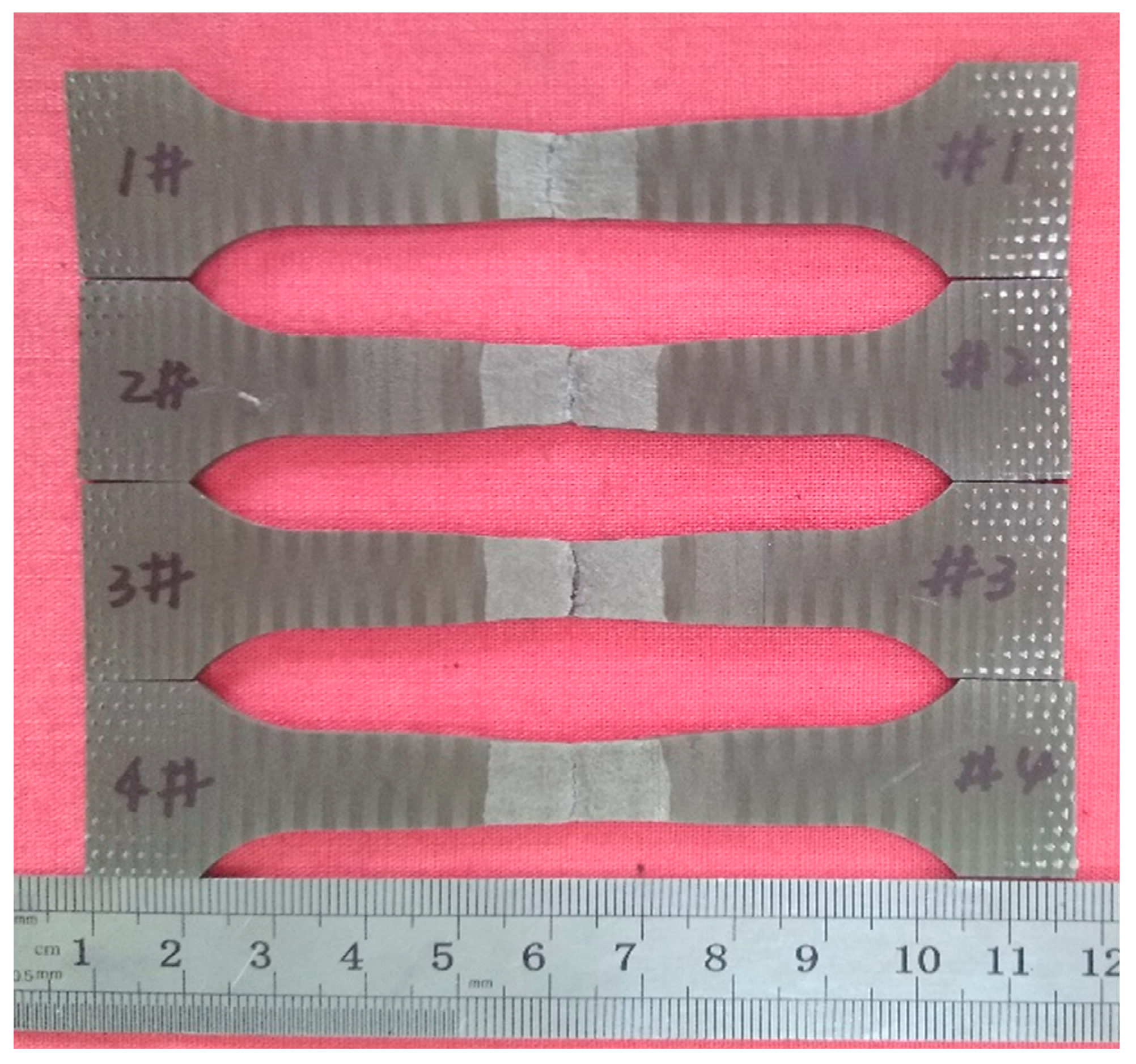
The optimum parameters of weld appearance of stainless steel UWW were 200 A-29 V-15 mm-2.0 mm/s. Under this parameter, the maximum tensile strength is 545 MPa, and the maximum impact toughness is 132 J/cm2, which are 73% and 79% of the base metal, respectively.

Author Contributions

Formal analysis, X.Z. and Q.C.; Investigation, X.Z. and C.S.X.; Resources, N.G.; Supervision, N.G.; Validation, Y.L.F.; Visualization, C.S.X. and H.C.; Writing – original draft, X.Z.

Funding

This research was funded by the Fundamental Research Funds for the Central Universities (Grant Nos. HIT.NSRIF.201602, HIT.NSRIF.201704, HIT. MKSTISP.201617), the Shandong Provincial Key Research and Development Plan (Grant No. 2016ZDJS05A07, 2017CXGC0922, 2018GGX103003) and the Natural Science Foundation of Shandong Province (Grant No. ZR2017QEE005, ZR2017PEE010).

Conflicts of Interest

The authors declare no conflict of interest.

References

  1. Guo, N.; Xu, C.S.; Du, Y.P. Influence of calcium fluoride on underwater wet welding process stability. Weld. World 2018, 63, 107–116. [Google Scholar] [CrossRef]
  2. Kralj, S.; Garašić, I.; Kožuh, Z. Diffusible hydrogen in underwater wet welding. Weld. World 2008, 52, 687–692. [Google Scholar]
  3. Łabanowski, J. Development of under-water welding techniques. J. Weld. Int. 2011, 25, 933–937. [Google Scholar] [CrossRef]
  4. Nemchinsky, V.A. Plasma parameters near a small anode in a high-pressure arc (gas metal arc welding). J. Phys. D Appl. Phys. 1994, 27, 2515–2521. [Google Scholar] [CrossRef]
  5. Pessoa, E.C.P.; Bracarense, A.Q.; Zica, E.M.; Liu, S.; Perez-Guerrero, F. Porosity variation along multipass underwater wet welds and its influence on mechanical properties. J. Mater. Process. Technol. 2006, 179, 239–243. [Google Scholar] [CrossRef]
  6. Rowe, M.D.; Liu, S.; Reynolds, T.J. The effect of ferro-alloy additions and depth on the quality of underwater wet welds. Weld. J. 2002, 8, 156–S. [Google Scholar]
  7. Li, H.L.; Liu, D.; Ma, Q.; Guo, N.; Song, X.G.; Feng, J.C. Microstructure and mechanical properties of dissimilar welds between 16Mn and 304L in underwater wet welding. Sci. Technol. Weld. Join. 2018, 4, 1–7. [Google Scholar] [CrossRef]
  8. Richardson, I.M.; Bucknall, P.W.; Stares, I. The influence of power source dynamics on wire melting rate in pulsed GMA welding. Weld. J.-N. Y. 1994, 73, 32–37. [Google Scholar]
  9. Zhang, Y.; Jia, C.B.; Zhao, B.; Hu, J.K.; Wu, C.S. Heat input and metal transfer influences on the weld geometry and microstructure during underwater wet FCAW. J. Mater. Process. Technol. 2016, 238, 373–382. [Google Scholar] [CrossRef]
  10. Jia, C.B.; Zhang, T.; Maksimov, S.Y.; Yuan, X. Spectroscopic analysis of the arc plasma of underwater wet flux-cored arc welding. J. Mater. Process. Technol. 2013, 213, 1370–1377. [Google Scholar] [CrossRef]
  11. Shi, Y.H.; Zheng, Z.-P.; Huang, J. Sensitivity model for prediction of bead geometry in underwater wet flux cored arc welding. Trans. Nonferr. Met. Soc. China 2013, 23, 1977–1984. [Google Scholar] [CrossRef]
  12. Fu, Y.L.; Guo, N.; Du, Y.P.; Chen, H.; Xu, C.S.; Feng, J.C. Effect of metal transfer mode on spatter and arc stability in underwater flux cored wire wet welding. J. Manuf. Process. 2018, 35, 161–168. [Google Scholar] [CrossRef]
  13. Molleda, F.; Mora, J.; Molleda, J.R.; Mora, E.; Mellor, Y.B.G. The importance of spatter formed in shielded metal arc welding. Mater. Charact. 2007, 58, 936–940. [Google Scholar] [CrossRef]
  14. Guo, N.; Du, Y.P.; Maksimov, S.; Feng, J.C.; Yin, Z.Q.; Krazhanovskyi, D.; Fu, Y.L. Study of metal transfer control in underwater wet FCAW using pulsed wire feed method. Weld. Word 2018, 62, 87–94. [Google Scholar] [CrossRef]
  15. Chen, H.; Guo, N.; Huang, L.; Zhang, X.; Feng, J.C.; Wang, G.D. Effects of arc bubble behaviors and characteristics on droplet transfer in underwater wet welding using in-situ imaging method. Mater. Des. 2019, 170, 107696. [Google Scholar] [CrossRef]
  16. Zhang, X.; Guo, N.; Xu, C.S.; Du, Y.P.; Chen, B.; Feng, J.C. Influence of CaF2 on microstructural characteristics and mechanical properties of 304 stainless steel underwater wet welding using flux-cored wire. J. Manuf. Process. 2019, 9, 138–146. [Google Scholar] [CrossRef]
  17. Zhang, M.J.; Chen, S.; Zhang, Y.Z.; Chen, Y.Z.; Chen, G.Y.; Bi, Z.M. Mechanisms for improvement of weld appearance in autogenous fiber laser welding of thick stainless steels. Metals 2018, 8, 625. [Google Scholar] [CrossRef]
Figure 1. Automatic underwater welding control platform: (a) control cabinet; (b) welding platform; (c) welding power supply.
Metals 09 00951 g001
Figure 2. Weld forming (a) grade 1; (b) grade 5.
Metals 09 00951 g002
Figure 3. Influence of welding parameters on welding formation. (a) welding current; (b) arc voltage; (c) CTWD; (d) welding speed.
Metals 09 00951 g003
Figure 4. Influence of welding parameters on welding spatter. (a) welding current; (b) arc voltage; (c) CTWD; (d) welding speed.
Metals 09 00951 g004
Figure 5. Interaction of welding current and arc voltage on welding spatter.
Metals 09 00951 g005
Figure 6. Interaction of welding speed and arc current on welding spatter.
Metals 09 00951 g006
Figure 7. Interaction of welding speed and arc voltage on welding spatter.
Metals 09 00951 g007
Figure 8. Weld macroscopic morphology. (a) before the deslagging; (b) after the deslagging.
Metals 09 00951 g008
Figure 9. The fracture positions of the tensile specimens.
Metals 09 00951 g009
Table 1. Chemical composition of 304 stainless steel (Wt. %).
ElementCrNiSiMnCPS
Content (%)18.0–20.08.0–10.5≤1.0≤2.0≤0.08≤0.045≤0.03
Table 2. Mechanical properties of 304 stainless steel.
ThicknessTensile StrengthImpact ToughnessHardness
10 mm712 MPa182 J/cm2235 HV
Table 3. Process parameters of the orthogonal test.
Specimen NumberWelding Current (A)Arc Voltage (V)CTWD (mm)Welding Speed (mm/s)FormingSpatter
118026251.512
21802820224
318030152.555
41803210321
522026202.534
62202825333
722030101.532
82203215235
92602615324
1026028102.544
112603025224
1226032201.532
133002610221
1430028151.533
153003020323
1630032252.533
Table 4. Optimal welding parameters.
Welding CurrentArc VoltageCTWDWelding Speed
200 A29 V15 mm2.0 mm/s

