Abstract
Inelastic deformation of metallic materials is one of the most effective mechanisms for the dissipation of energy input to a structure by an earthquake. Metallic dampers are special devices that resort to this source of energy dissipation, proving to be a cost-efficient solution for the seismic protection of structures. Two important issues arise when implementing metallic dampers in real structures: (1) Inelastic deformations cause damage that must be quantified after an earthquake to decide upon their eventual replacement; (2) dampers must possess an energy dissipation capacity large enough to endure severe earthquakes. This paper focuses on a particular type of metallic damper consisting of slit-plates made of stainless steel, applied to reinforced concrete frames with rocking columns at the first story. In particular, a new damage index based on the metallic magnetic memory (MMM) method is proposed and validated experimentally to quantify the damage of slit plate dampers subjected to cyclic loadings. Further, the seismic response of a frame with rocking columns that incorporate the damper is obtained to demonstrate that it can endure severe earthquakes without failing, and to emphasize the relevance of the proposed MMM damage index that would make its replacement after a severe earthquake unnecessary.
1. Introduction
The traditional seismic design approach is based upon providing structures with a combination of strength and plastic deformation capacity (ductility) to resist major earthquakes. For severe earthquakes, conventional frame structures are conscientiously detailed to dissipate energy through plastic deformations at beam ends and at column bases, preventing catastrophic collapse. Yet this implies structural damage throughout the structure after the earthquake, which in many cases is not economically feasible to repair. In recent years, an alternative design trend has been growing: Concentrating the plastic strain energy dissipation demand in limited parts of the structure. In particular, special elements called passive energy dissipation devices, or simply dampers, are located in these parts. The main role of the dampers is to absorb or consume most of the energy input by the earthquake, thereby reducing (or even cancelling) the energy dissipation demand on primary structural elements (i.e., beams and columns in frame structures) and minimizing possible structural damage. One highly efficient mechanism for dissipating energy input from earthquakes is through the inelastic deformation of metals. The devices that mobilize this source of energy dissipation are called metallic dampers.
After moderate ground motions or even after a large earthquake, metallic dampers do not necessarily need to be replaced. However, deciding whether the dampers require replacement calls for a reliable and non-destructive evaluation of the level of damage. Simple visual inspection is not enough to judge the “health” of the damper, because damage caused by earthquakes is often, yet not always, a cumulative process. In case of near-fault impulse ground motions, the energy is input by the earthquake into the structure in a very short period of time and damage is a sudden process. The degradation of the structure can also lead, for example, to sudden stiffness reductions (i.e., sudden damage). Past investigations [1] have proven that the level of damage of steel elements subjected to imposed inelastic cyclic deformations can be reliably estimated from the force-displacement, Q-δ, curves. This can be done by decomposing the Q-δ curves into the so-called skeleton part and Bauschinger part and calculating an ID index that is based on the amount of energy dissipated in each part [1]. Yet measuring Q and δ during an earthquake entails installing expensive instrumentation that must be well maintained to ensure it will work properly under events (earthquakes) that have a very low probability of occurrence. An alternative is the use of non-destructive testing (NDT) methods. One NDT method consists of conducting vibration tests [2], and performing modal analysis to relate the damage to variations of natural frequencies and modal damping factors. Other methods rely on pulse-echo ultrasonic Tests (UT) by studying the effects of stresses in the relationship between Poisson ratios [3] or the ultrasonic attenuation coefficient [4]. The present paper investigates an alternative referred to in the literature as the metal magnetic memory (MMM) technique.
The MMM method is relatively new. It was conceived when early observations confirmed the ability of metals to magnetize, even when they were not subjected to an external magnetic field [5,6,7]. Nowadays, the developed MMM method is based on the self-magnetic leakage field (SMLF), which is an irreversible variation of the metal magnetization in areas with failure planes or dislocations (Figure 1), areas under applied stresses, or areas having some heterogeneity in the structure of the material. It can be defined as a non-destructive test based on the analysis of the SMLF distribution over the surface of an element to determine stress concentration zones (SCZ), imperfections, and heterogeneities in the microstructure of the material [8]. It therefore holds high potential both for detecting existing damage and for predicting damage (SCZ) in materials and structures [9]. In this respect, the MMM technique is the only NDT method able to assess or predict the damage without any contact with the specimen surface. This fact is very important in real structures, since dampers are usually covered by brick veneers, casing, cement plaster etc., and the access to its surface is often restricted. Furthermore, the equipment used for an MMM inspection is easy to handle and characterized by its high portability.
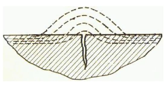
Figure 1.
Self-magnetic leakage field in a surface crack.
Some previous research on the damage of steel components has involved the MMM technique [10,11,12,13,14,15,16]. To date, however, no published study has applied the MMM technique for inspection of metallic dampers with posterior validation by means of a reliable mechanical damage index.
This paper focuses on a particular metallic damper developed by the authors and consisting of stainless steel plates with slits (“slit-plate” damper hereafter). Several slit-plate dampers were subjected to low-frequency cyclic forced displacements up to different levels of damage, including failure. The dissipated plastic strain energy associated with each level of damage is computed and used to calculate the mechanical index of damage, ID. This ID index is basically the ratio between the amount of dissipated energy and the maximum (ultimate) amount of energy that the damper can dissipate until failure when subjected to seismic loadings. Next, the MMM technique is used to obtain the distribution of the gradient of the SMLF. From this distribution, a new damage index referred to hereafter as Em is proposed. The Em index quantifies the variation of the area enveloped by the gradient distribution of SMLF. Comparison of the new index with the mechanical index ID showed a good correlation in the range of ID of practical interest (between 0 and 0.8). It is worth emphasizing that calculation of the ID index calls for recording the force-displacement curve experienced by the damper during the earthquake. In contrast, the new Em only requires MMM testing after the earthquake.
The “slit-plate” damper was implemented in reinforced concrete (RC) frames with rocking columns in the first story. The energy dissipation demand on the slit-plate dampers under severe earthquakes was obtained through non-linear time history analyses, and it was compared with the dampers′ ultimate energy dissipation capacity in terms of the damage index ID. It is shown that the “slit-plate” damper can dissipate the energy input by severe earthquakes in frames with rocking columns, with limited damage; hence the significance of the proposed damage index Em to avoid replacing the dampers after a severe earthquake. Rocking structures have been investigated since the 1970s [17,18,19,20,21,22,23] and have evolved in two directions [24]. One direction, developed mainly in Russia (or the USSR), stems from the concept of “kinematic support” [20,21,22,23]. The rocking structure dealt with in this paper is in line with the other direction, developed mainly in the USA [17,18] and New Zealand [19], and is shown in Figure 2a. It consists of a superstructure that is freely supported on free-standing RC rocking columns located on the first (ground) story. Under lateral seismic loads the superstructure is allowed to uplift, and this limits the forces transmitted to the structure and to the foundation. The movement of the rocking column is achieved by terminating the longitudinal reinforcement before it reaches the beam-column joint and the column foundation interface. To control the lateral displacements, mechanical restrainers (e.g., post-tensioning cables [25]) and energy dissipation devices are installed at the ends of the rocking columns [26,27]. Figure 2b illustrates a particular solution, an RC frame with rocking columns recently developed by the second author that implements the “slit-plate” damper. In this solution, the rocking column is vertically restrained with a steel bar passing though the centerline of the column, while anchored at the top beam and free to slip at the bottom end. A detailed description of this rocking structure is beyond the scope of this paper.
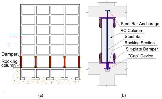
Figure 2.
Reinforced concrete (RC) frame structure with rocking columns and slit-plate dampers: (a) Elevation of the RC frame; (b) detail of the rocking columns of the first story.
2. Description of the “Slit-Plate” Damper
The slit-plate damper is shown in Figure 3. It is built from a stainless-steel plate by cutting a number of slits, leaving a number of strips between them. It then has two “exterior flanges” and one “interior flange” connected by strips between consecutive slits. The damper is intended to connect two parts of the structure that undergo relative displacements. The “exterior flanges” of the damper are fixed to one part and the “interior flange” to the other part. When the “interior flange” is forced to deform in the same direction and opposite sense as the “exterior flanges”, the strips experience shear and double curvature bending; this causes inelastic deformation. The slit-plate damper is intended to be installed at both ends of the rocking columns of the first story, as shown in Figure 4. The exterior flanges are fixed with bolts to the steel plates that cover the ends of the column and protect them during the rocking motion (“extreme steel tube” in Figure 4). The interior flange is fixed with bolts to a vertical plate that is welded to the horizontal plate on which the columns rock (“foundation steel plate” in Figure 4). The slit-plate damper can be easily uninstalled for inspection or replacement.
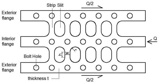
Figure 3.
Stainless-steel slit-plate damper.
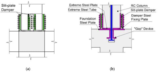
Figure 4.
Installation of the slit-plate damper at the ends of the rocking columns: (a) Elevation; (b) section through the plane of the frame.
Five slit-plate dampers similar to the one shown in Figure 5 were built. The specimens, henceforth called DC1–DC5, were made of hot-rolled stainless steel, grade 304-AISI. The mechanical properties of the material are as follows: Yield stress fy = 230 N/mm2, maximum stress fB = 620 N/mm2, Young’s modulus E = 2 × 10⁵ N/mm2 and shear modulus G = 1 × 10⁵ N/mm2. The specimens were mounted in the experimental set-up shown in Figure 6. It consisted of two hollow steel square sections, one inside the other, arranged in a telescopic configuration. The exterior tube was clamped by bolts to the loading head and the interior tube was solidly attached to the base of a universal testing machine, SAXEWAY T1000, from the company MOOG Inc. (East Aurora, New York, NY, USA), with a maximum load capacity of 1000 kN. The exterior flanges of the slit-plate damper were fixed with bolts to the exterior tube. The interior flange of the slit-plate damper was also fixed with bolts to the interior tube, through a rectangular window opened in the exterior tube.
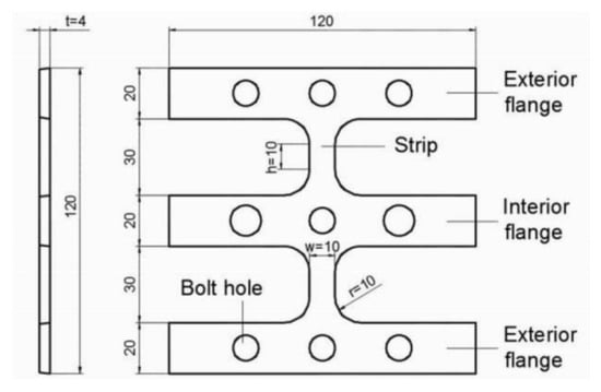
Figure 5.
Test specimen (nominal dimensions in mm).
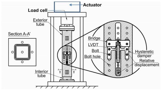
Figure 6.
Experimental setup used for the cycling tests.
To test the specimens, relative displacements were imposed between the exterior and interior tubes through the actuator. This caused relative displacements between the exterior and the interior flanges. Figure 7 depicts the deformation pattern of the specimen as a consequence of this relative displacement. The shaded area indicates the approximate region where plastic deformations took place. Also shown in Figure 7 is the distribution of bending moments in the strips.
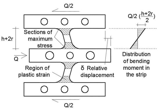
Figure 7.
Relative displacement between interior and exterior flanges.
All test specimens were subjected to cycles of increasing amplitude, 0.4 mm in each cycle, following the loading history depicted in Figure 8. This increment of amplitude in each cycle is five times the yield displacement of the specimen calculated with Equation (3). The frequency of the cyclic tests was 0.05 Hz. The frequency has a significant effect on the material properties of the stainless steel. More precisely, the yield stress increases with increasing frequency, while the Young’s modulus remains basically constant. The low cycle fatigue live decreases with decreasing frequency. Each of the specimens (DC1–DC5) reached a different number of cycles in order to induce a different level of damage Di, as indicated in Table 1. Thus, test specimen DC1 was subjected to two cycles and reached the damage level referred to as D1; test specimen DC2was subjected to six cycles and reached the level of damage D2, and so on. Test specimen DC5 was tested until failure.
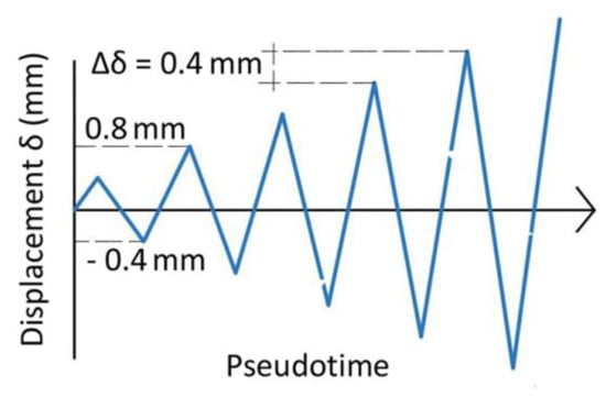
Figure 8.
Load patterns applied to specimens DC1 to DC5.

Table 1.
Number of the cycle and maximum displacement reached.
3. MMM Inspection of Specimens
The H1 and H2 scan trajectories shown in Figure 9 were traced along the edges of the central flange. These trajectories were selected because they cross the section of the steel strips where the bending moment is maximum (see Figure 7), and therefore where the maximum plastic strains develop.
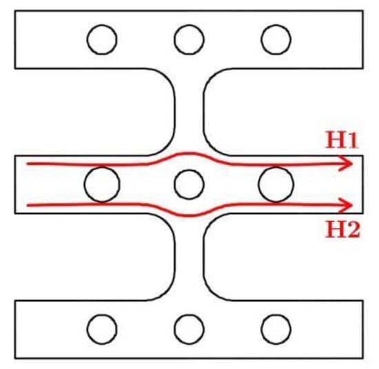
Figure 9.
Scan trajectories H1 and H2 during the metallic magnetic memory (MMM) inspection.
TSC-3M-12 ENERGODIAGNOSTIKA equipment supplied by PREDITEST Company (Prague, Czech Republic), was used for the MMM inspection of the specimens (Figure 10). It consists of a scanning roller of the 2M type, which can measure in two directions, X and Y. The device has a scroll that transmits to the equipment the displacement during scanning.
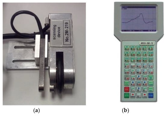
Figure 10.
Instrumentation of the MMM inspection. (a) Scanning roller device with a fluxgate magnetometer type 2M. (b) Measurement equipment type TSC-3M-12.
Three measurements were carried out for each trajectory, i.e., six for each specimen. A scanning rate was set in the MMM equipment in order to provide data every millimeter, regarding the following four parameters:
- -
- HL, x: the normal component of the self-magnetic field intensity.
- -
- HL, x/dx: the gradient of the normal component of self-magnetic field intensity in the x-direction (scanning direction).
- -
- HL, y: the tangential component of the self-magnetic field intensity.
- -
- HL, y/dx: the gradient of the tangential component of self-magnetic field intensity in the x-direction (scanning direction).
The analysis of the MMM inspection was performed by using MMM System 3.0 software, supplied by Energodiagnostika Co. Ltd (Reutov, Moscow, Russia), and concerned only the normal component of the SMLF. More precisely, the gradient HL, x/dx that is able to quantify the stress concentration or damage.
4. Ultimate Energy Dissipation Capacity and Mechanical Damage Index ID
Figure 11a shows the typical force displacement, Q-δ, curve obtained by testing a metallic damper under cyclic loading until failure. Failure of the damper is assumed to occur when the strength starts to decrease steadily under increasing forced displacements. The curve can be decomposed into two parts, the skeleton part and the Bauschinger part [1]. The skeleton part is formed by sequentially connecting the segments of the Q-δ curve that exceed the load level attained in preceding cycles in the same domain of loading (indicated with a square symbol in Figure 11a). For the example shown in Figure 11a, this means sequentially connecting the segments labeled 0–1, 5–6, 11–12, 17–18, 23–24, 29–30 in the positive domain, and 2–3, 8–9, 14–15, 20–21, 26–27 in the negative domain. The skeleton part obtained in this way is the curve shown in Figure 11b. As shown in previous studies [1], the skeleton curves in the positive and negative domains are almost coincident and can be approximated by a trilinear curve (plot with dash line in Figure 11b) that is characterized by the yield force Qy, the yield displacement δy, the force corresponding to the onset of the second segment QB, the first plastic stiffness Kp1 and the second plastic stiffness Kp2. For slit-plate dampers, Qy and δy can be easily predicted from the geometry and the mechanical properties of the steel with the following equations [28] based on fundamental principles of the strength of materials:
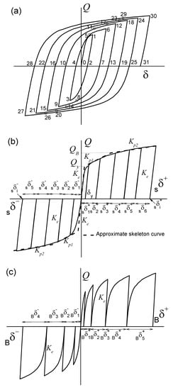
Figure 11.
Decomposition of the force displacement, Q-δ, curve: (a) Entire Q-δ curve; (b) skeleton part; (c) Bauschinger part.
Here, w and h are the width and height of the strip, respectively, r is the radius of the end part of the strip (see Figure 3), t is the thickness of the plate, n is the total number of strips and h’ = h + [2r2/(h + 2r)]. Note that Qy and QB are taken as the minimum between two values; one is associated with the flexural yielding of the strip, and the other with the shear yielding. The maximum displacements in the skeleton part in the positive and negative domains are denoted herein by and (see Figure 11b).
The Bauschinger part is constituted by the segments that begin at Q = 0 and terminate at the maximum load level previously attained, in preceding cycles in the same loading domain. For the example shown in Figure 11a, the Bauschinger part comprises the segments labeled as 4–5, 10–11, 16–17, 22–23, 28–29 in the positive domain, and 7–8, 13–14, 19–20, 25–26 in the negative domain of loading.
In Figure 11a, segments 1–2, 6–7, 12–13, 18–19, 24–25, 30–31 in the positive domain and 3–4, 9–10, 15–16, 21–22, 27–28 in the negative domain are unloading paths whose slope (i.e., stiffness) coincides with the initial elastic stiffness Ke (= Qy/δy). The Bauschinger part obtained in this way is shown in Figure 11c.
Up to a given point , ) of the Q-δ curve, the area enveloped by the skeleton curve in the positive and in the negative domains is respectively referred to herein as and . Also, for each domain of loading, the areas enveloped by the Bauschinger part will be referred to as and . The sum () in the positive domain, and () in the negative domain, represent the total plastic strain energy dissipated by the damper in the positive and in the negative domains of loading. For convenience, the above energies can be expressed in nondimensional form by the following ratios:
and the maximum displacements in the skeleton part, , , can be normalized as follows:
The ultimate values of and , i.e., when the metallic damper fails, will be denoted hereafter by and . They represent the (normalized) ultimate energy dissipation capacity of the damper in each domain of loading. Past research [1] showed that or depend on the history of loading applied, i.e., and vary with , , and . For metallic dampers subjected to flexural/shear deformations without axial forces, , or can be estimated with the following expression [1]:
where and . Here, and must be taken equal to and to obtain and equal to and to calculate . It is worth emphasizing that Equation (6) has been obtained specializing the formula presented in Reference [1] to the particular slit-plate damper investigated in this study. As for b, it is an empirical parameter that is determined testing a damper under cyclic loading up to failure, as follows [1]:
where , , , are the values of , , , for a specimen tested to failure. The mechanical damage in a metallic damper subjected to arbitrarily applied cyclic loading up to a point (Qi, δi) can be quantified using the following damage index ID [1]:
The damage index ID has been validated with extensive experimental results [1]. The value IDi = 0 indicates no damage, while IDi ≥ 1 means failure. Since ID is the ratio between the amount of dissipated energy and the maximum amount of energy that the damper can dissipate until failure, ID can likewise be interpreted as the fraction of the ultimate energy dissipation capacity of the damper consumed up to a given level of damage i.
5. Results
5.1. Evaluation of the Mechanical Index of Damage ID
Figure 12 shows the force-displacement curves, Q-δ, obtained from the cyclic tests. Due to the strain hardening of the material, the amplitude of the loops along the vertical axis increases in each consecutive cycle. The shape of the hysteretic loops indicates that the slit-plate damper exhibits stable energy dissipation characteristics. Each cyclic curve was decomposed as explained in Section 4. For illustrative purposes, Figure 13 shows the skeleton part and the Bauschinger part obtained for specimen DC5 in the positive domain. Finally, the mechanical index of damage ID defined by Equation (8) was calculated for each specimen and is shown in Table 2. It can be seen in the Table that specimen DC1 was very lightly damaged, specimen DC3 consumed about 1/3 of its ultimate energy dissipation capacity, and DC5 attained its ultimate energy dissipation capacity.
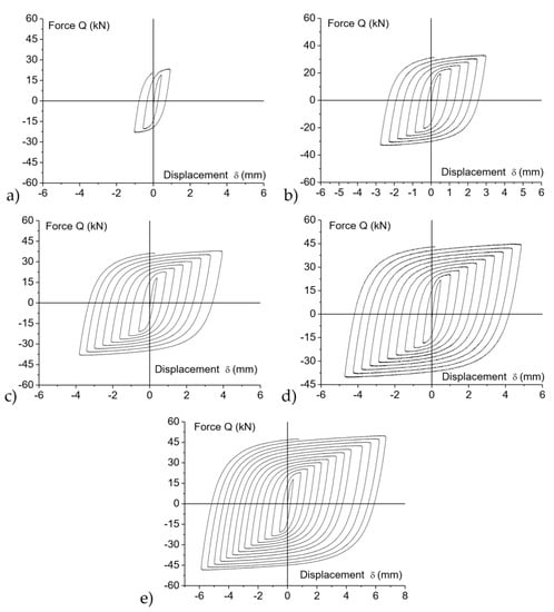
Figure 12.
Hysteresis curves obtained from the cyclic tests for specimens: (a) DC1; (b) DC2; (c) DC3; (d) DC4; (e) DC5.
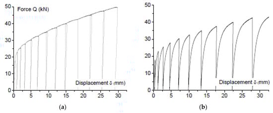
Figure 13.
Decomposition of the cyclic curve of specimen DC5 into: (a) Skeleton, and (b) Bauschinger part; both in the positive load domain.
Table 2.
Mechanical index of damage ID.
5.2. Results and Interpretation of the MMM Inspection
Figure 14 represents the magnetogram that includes the SMLF intensity and gradient curves corresponding to trajectories H1 and H2 in specimen DC5. It can be clearly seen that the distribution of intensity and gradient reflect the damage at the end of the strip.
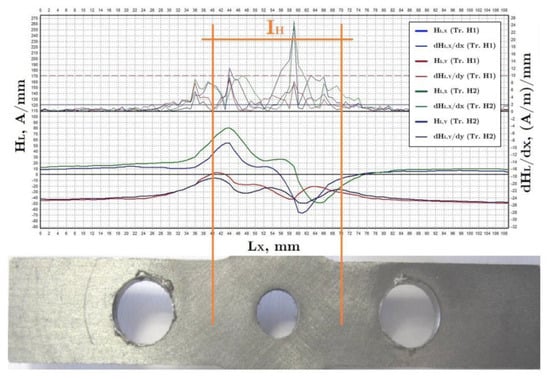
Figure 14.
Magnetogram of the trajectories H1 and H2 in the specimen DC5.
The magnetograms in Figure 15 correspond to the SMLF gradient measurements in specimens DC1, DC2, DC4 and DC5 with different levels of damage. It is clearly seen how the distribution increases as the level of damage in the specimen increases. In specimen DC1 (damage level D1), the gradient level is generally low and uniform. In specimens DC2 (damage level D2) and DC4 (damage level D4), the gradient distribution tends to concentrate in the center of the trajectory, i.e., around the end of the strip, and the maximum peak reaches values of 5 and 10 (A/m)/mm, respectively. For specimen DC5 (damage level D5), the concentration of the gradient distribution in the center is significantly accentuated and a maximum value of 31 (A/m)/mm is reached.
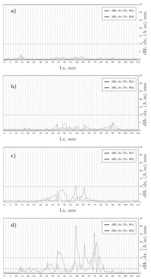
Figure 15.
Magnetograms of trajectories H1 and H2 in specimens (a) DC1, (b) DC2, (c) DC4 and (d) DC5.
The area under the gradient distribution of the SMLF, EdHL, is proposed in this paper as an indicator of the level of damage. EdHL was calculated for the interval IH = (45–75) mm (see Figure 14) of trajectories H1 and H2. Thus, using EdHL, the present work proposes a MMM index, EM,i, which is the difference between the value of EdHL calculated for a specimen with a certain level of damage (Di, EdHL,i) and the value of EdHL measured for the undamaged specimen (D0, EdHL,0), i.e.;
The global damage index EM was calculated for the specimens tested in this study as the average of six measurements, which were obtained from three trials performed in trajectory H1 and three trials performed in trajectory H2. Results are shown in Figure 16. Figure 16a shows the average value of EM versus the qualitative description of the level of damage used in Table 1 (i.e., D0 to D5). Also shown in Figure 16a with error bars is the dispersion of EM in the six trials. A growing trend of EM is seen as the level of damage increases. Moreover, the dispersion of the values of EM is very small.
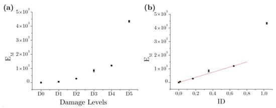
Figure 16.
MMM inspection through trajectories H1 and H2. (a) Mean and standard deviation of the EM index for each Di. (b) Correlation EM-ID.
Figure 16b shows the average EM versus the quantitative description of damage in terms of index ID. Due to its high ultimate energy dissipation capacity, the level of damage expected in the slit-plate damper, for example, after five low intensity earthquakes in a high seismicity region or after a single high intensity earthquake in a region of moderate seismicity, is low (as discussed next in Section 6). On the other hand, levels of damage beyond about ID = 0.8 would make advisable the replacement of the dampers so as not to compromise a reasonable margin of safety for the structure. This means that the range of values of interest for ID are approximately between ID = 0 and ID = 0.8. In this range, as seen in Figure 16b, there is a strong and linear correlation (correlation coefficient R2 = 0.9942) between EM and ID. In sum, for the range of levels of damage of interest, inspection by means of the MMM method, along the trajectories shown in Figure 9, allows one to obtain indirectly and reliably the index of mechanical damage ID.
6. Seismic Response of RC Frames with Rocking Columns Equipped with Slit-Plate Dampers
A prototype RC frame having six stories with rocking columns in the first story was designed. Slit-plate dampers of the type investigated in this paper were installed at both ends of each rocking column. The geometry of the frame is shown in Figure 2a. The size of the columns is 0.50 × 0.50 m2 in the first story, 0.45 × 0.45 m2 in the second and 0.40 × 0.40 m2 in the upper stories; the dimensions of the columns are the same in each story, except the exterior columns of the fifth and sixth stories where the section of the column is reduced to 0.35 × 0.35 m2. All beams have 0.30 (width) × 0.45 (depth) m2. The design of the RC members was carried out in accordance with Eurocode 2 [29]. The gravity loads considered were 3.57 kN/m2 for the slab’s own weight, 2.5 kN/m2 for other dead loads, and 2 kN/m2 for live loads. A wind pressure of 1.42 kN/m2 was also considered. The seismic design was carried out in view of Eurocode 8 [30], assuming a design spectrum Type I, a soil type C and a peak ground acceleration (PGA) of 0.23g (here g is the acceleration of gravity). The concrete compression strength adopted was fc = 25 N/mm2 and the yield strength for reinforcing steel fsy = 500 N/mm2. The total mass of the frame was M = 530,468 kg.
A numerical model was developed for the prototype structure using the software Opensees [31]. Excepting the columns of the first story, all beams and columns were modelled using frame elements. The columns of the first story (rocking columns) were modelled as infinitely stiff frame members with three non-linear springs working in parallel at either end. The first spring represents the contribution of the rocking column, the second spring the contribution of the steel bar and the third spring the slit-plate dampers. The hysteretic behavior of the third spring follows the RambergOsgood model implemented in Opensees [31]. This model was calibrated to reproduce the hysteretic curves obtained from the cyclic tests presented in Section 5.1. Two slit-plate dampers were installed at each end of each rocking column—one at each side of the column—as shown in Figure 4b. The values of the parameters that characterize each slit-plate damper are: n = 38, t = 10 mm, w = 10 mm, h = 50 mm and r = 10 mm. The mechanical properties adopted for the material are the same as for the tested specimens (see Section 2).
The frame was subjected to the horizontal component of seven ground motions acting in the plane of the frame. The characteristics of the earthquakes, as shown in Table 3, were as follows: Mw the moment magnitude, Rrup the distance to the rupture fault, vs30 the shear wave velocity of the soil, and PGA. Each earthquake was scaled to two levels of intensity (Level 1 and Level 2). Each level is characterized by the total energy ED input by the earthquake, expressed in terms of equivalent velocity SV (=). The equivalent velocity for Level 1 was SV = 0.6 m/s, and represents approximately a low intensity earthquake in a high seismicity region. The equivalent velocity for Level 2 was SV = 0.9 m/s and represents approximately a high intensity earthquake in a moderate seismicity region. Nonlinear time history analyses were conducted to obtain the performance of the frame and the hysteretic force-displacement, Q-δ, curve of the slit-plate dampers. Figure 17 shows the averaged (throughout the seven ground motions) inter-story drifts, peak response accelerations and amount of energy dissipated through plastic deformations by each story, for the two levels of intensity considered. It can be seen that, as expected, the inter-story drift (Figure 17a) is significantly larger at the story with rocking columns (first story), and most of the plastic strain energy (Figure 17c) is dissipated in this story by the slit-plate dampers. The peak acceleration (Figure 17b) is similar in all stories. Figure 18 shows the Q-δ curve exhibited by the slit-plate dampers installed in the frame, under the Imperial Valley-06 earthquake, scaled to Level 2. The Q-δ curves were decomposed as explained in Section 4 and the mechanical index of damage ID at the end of the earthquake was calculated. The results are shown in Table 4. It can be seen in the Table that for a single earthquake of Level 1 the slit-plate dampers consumed an average of about 5% of their ultimate capacity. For a single earthquake of Level 2, the slit-plate dampers consumed an average of about 6% of their ultimate capacity. Seismic codes require metallic dampers to endure five low intensity earthquakes and one high intensity earthquake. If the building is located in a region of high seismicity, the five low intensity earthquakes would consume about 5 × 5 = 25% of its ultimate capacity. If the building is located in a region of moderate seismicity, the high intensity earthquake would consume about 6% of its ultimate capacity. Using the correlation between IDi and EM shown in Section 5, in a real scenario the dampers could be inspected by means of the MMM technique after the earthquake to obtain IDi, and it would be concluded that they do not need to be replaced, since an important portion of their ultimate energy dissipation capacity still remains.
Table 3.
Characteristics of ground motions.
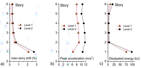
Figure 17.
Frame performance in terms of: (a) Inter-story drift, (b) peak acceleration; and (c) dissipated energy.
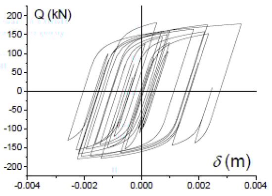
Figure 18.
Force-displacement curve of the slip-plate dampers under Imperial-Valley-6 earthquake scaled to Level 2.
Table 4.
Mechanical index of damage IDi of the slit-plate dampers installed in frame.
7. Conclusions
This study is focused on a special type of metallic energy dissipation device (damper) developed by the authors for the seismic protection of buildings and infrastructures. The damper consists of stainless-steel plates with slits (slit-plate damper). This work validates the use of the metallic magnetic memory (MMM) technique for quantitative damage evaluation of metallic dampers. In particular, a new damage index EM based on the area under the gradient distribution of the SelfMagnetic Leakage Field is proposed. Several metallic dampers were tested under cyclic loading to induce several levels of damage, including failure. The level of damage of each specimen was evaluated with the new index EM and compared with a traditional mechanical index ID based on the decomposition of the force-displacement curve endured by the damper. It is concluded that, for the range of levels of damage of interest, the proposed damage index Em is well-correlated linearly with the mechanical damage index ID from small damage levels. Finally, the slit-plate damper is applied to a six-story frame with rocking columns at the first story and subjected to seismic loading. The slit-plate damper was found to have an energy dissipation capacity large enough to endure severe earthquakes without exhausting its ultimate energy dissipation capacity; moreover, application of the MMM technique in conjunction with the damage index Em proposed in this investigation would make it unnecessary to replace the metallic dampers after a severe earthquake. The results of this study can be applied to slit-plates with different dimensions of strips.
The proposed MMM technique was validated by means of metallic dampers subjected to quasistatic loads and under simple histories of imposed deformations (i.e., cycles of incremental amplitude). Yet real earthquakes would subject the dampers to dynamic loadings, and to complex and arbitrarily changing histories of deformation. These are two limitations of the present study, to be addressed by the authors in future work. More precisely, the MMM technique and the proposed damage index will be validated experimentally through seismic-type dynamic tests on large scale frames with rocking columns equipped with slit-plate dampers, using the 3 × 3 m2 shake table of the University of Granada. Although it is out the range of practical interest, additional tests are needed to understand the relation between ID and EM for ID = 0.9–0.95, that is, when the slit-plate damper is very severely damaged and close to failure.
Author Contributions
G.R.-G. and A.B.-C. conceived and designed the slit-plate dampers and the cyclic tests; G.R.-G. conceived the application of the slit-plate dampers to frames with rocking columns, developed the numerical models and conducted the numerical simulations; A.B.-C., D.G.-L. and C.A. performed the cyclic experiments; G.R.-G. and D.G.-L. calculated the mechanical damage index; C.A. carried out the MMM tests; C.A., A.G. and F.R. carried out the calculations and data analysis; all authors contributed to write the paper.
Funding
This research was funded by Consejería de Economia, Innovación, Ciencia y Empleo, Junta de Andalucía, grant number TEP-02429, by Ministerio de Economía, Industria y Competitividad, Gobierno de España, grant number BIA2017 88814 R, and received funds from the European Union (Fonds Européen de Dévelopment Régional). The APC was funded by Ministerio de Economía, Industria y Competitividad, Gobierno de España, grant number BIA2017 88814 R.
Acknowledgments
The authors thank the PREDITEST Company, from the Czech Republic, and in particular Svoboda, for support in MMM equipment, measurements, and scientific discussions.
Conflicts of Interest
The authors declare that they have no conflict of interest.
References
- Benavent-Climent, A. An energy-based damage model for seismic response of steel structures. Earthquake Eng. Struct. Dyn. 2007, 36, 1049–1064. [Google Scholar] [CrossRef]
- Kouris, L.A.S.; Penna, A.; Magenes, G. Seismic damage diagnosis of a masonry building using short-term damping measurements. J. Sound Vib. 2017, 394, 366–391. [Google Scholar] [CrossRef]
- Kurashkin, K.V.; Mishakin, V.V. Ultrasonic estimation of residual stresses. Inorg. Mater. 2013, 4, 54–58. [Google Scholar] [CrossRef]
- Ma, S.; Yuan, K.; Zhang, H.; Wei, X. Evaluation of fracture damage of SUS306 structural steel using ultrasonic testing. J. Shanghai Univ. 2009, 13, 279. [Google Scholar] [CrossRef]
- Kikuchi, Y. Magnetostrictive materials and applications. IEEE Trans. Magn. 1968, 4, 107–117. [Google Scholar] [CrossRef]
- Hornreich, R.M.; Rubinstein, R.J. Magnetostrictive phenomena in metallic materials and some of their device applications. IEEE Trans. Magn. 1971, 7, 29–48. [Google Scholar] [CrossRef]
- Doubov, A.A. A study of metal properties using the method of magnetic memory. Met. Sci. Heat Treat. 1997, 39, 401–402. [Google Scholar] [CrossRef]
- ISO 24497-3:2007. Non-Destructive Testing–Metal Magnetic Memory–Part 3: Inspection of Welded Joints; International Organization for Standardization: Geneva, Switzerland, 2007. [Google Scholar]
- Doubov, A.A. Principal features of metal magnetic memory method and inspection tools as compared to known magnetic NDT methods. In Proceedings of the Sixteenth Annual World Conference on Non-Destructive Testing, Montreal, QC, Canada, 30 August–3 September 2004. [Google Scholar]
- Doubov, A.A. Screening of weld quality using the magnetic metal memory effect. Weld. World 1998, 41, 196–198. [Google Scholar]
- Mao, W.; Atherton, D.L. Effect of compressive stress on the reversible and irreversible differential magnetic susceptibility of a steel cube. J. Magn. Magn. Mater. 2000, 214, 69–77. [Google Scholar] [CrossRef]
- Doubov, A.A. A technique for monitoring the bends of boiler and steam-line tubes using the magnetic memory of metal. Therm. Eng. 2001, 48, 289–295. [Google Scholar]
- Doubov, A.A.; Demin, E.A.; Milayev, A.I.; Steklov, O.I. The experience of gas pipeline stress–strain state control with usage of the metal magnetic memory method as compared with conventional methods and stress control means. Weld. World 2002, 46, 29–33. [Google Scholar] [CrossRef]
- Li, Z.; Dixon, S.; Cawley, P.; Jarvis, R.; Nagy, P.B. Study of metal magnetic memory (MMM) technique using permanently installed magnetic sensor arrays. In Proceedings of the AIP Conference, Atlanta, GA, USA, 17–22 July 2016. [Google Scholar] [CrossRef]
- Stegemann, R.; Cabeza, S.; Pelkner, M.; Lyamkin, V.; Sonntag, N.; Bruno, G.; Skrotzki, B.; Kreutzbruck, M. Evaluation of high spatial resolution imaging of magnetic stray fields for early damage detection. In Proceedings of the AIP Conference, Atlanta, GA, USA, 17–22 July 2016. [Google Scholar] [CrossRef]
- Jarvis, R.; Cawley, P.; Nagy, P.B. Current deflection NDE for pipeline inspection and monitoring. In Proceedings of the AIP Conference, Minneapolis, MI, USA, 26–31 July 2016. [Google Scholar] [CrossRef]
- Huckelbridge, A.; Clough, R. Earthquake Simulation Tests of a Nine Story Steel Frame with Columns Allowed to Uplift; Report EERC-77/23; University of California at Berkeley: Berkeley, CA, USA, 1977. [Google Scholar]
- Beck, J.L.; Skinner, R.I. The seismic response of a reinforced concrete bridge pier designed to step. Earthquake Eng. Struct. Dyn. 1973, 2, 343–358. [Google Scholar] [CrossRef]
- Sharpe, R.D.; Skinner, R.I. The seismic design of an industrial chimney with rocking base. Bull. New Zealand 1983, 16, 98–106. [Google Scholar]
- Polyakov, S.V. Design of Earthquake Resistant Structures; MIR Publishers: Moscow, Russia, 1974. [Google Scholar]
- Smirnov, V.; Eisenberg, J.; Vasileva, A. Seismic Isolation of buildings and historical monuments. Recent developments in Russia. In Proceedings of the 13th World Conference on Earthquake Engineering, Vancouver, BC, Canada, 1–6 August 2004. [Google Scholar]
- Uzdin, A.M.; Doronin, F.A.; Davydova, G.V.; Avidon, G.E.; Karlina, E.A. Performance analysis of seismicinsulating elements with negative stiffness. Soil Mech. Found. Eng. 2009, 46, 15–21. [Google Scholar] [CrossRef]
- Eisenberg, J.M.; Smirnov, V.I. Development of Earthquake Protection Structural Systems Based on Response Control. In Proceedings of the 15 World Conference on Earthquake Engineering, Lisbon, Portugal, 24–28 September 2012. [Google Scholar]
- Bachmann, J.A.; Vassiliou, M.F.; Stojadinovic, B. Dynamics of rocking podium structures. Earthquake Eng. Struct. Dyn. 2017, 46, 2499–2517. [Google Scholar] [CrossRef]
- Mander, J.B.; Cheng, C.T. Seismic Resistance of Bridge Piers Based on Damage Avoidance Design; Technical Report for National Center for Earthquake Engineering Research; National Center for Earthquake Engineering Research, State University of New York at Buffalo: New York, NY, USA, 1997. [Google Scholar]
- Viti, S.; Cimellaro, G.P.; Reinhorn, A.M. Retrofit of a hospital through strength reduction and enhanced damping. Smart Struct. Syst. 2006, 2, 339–355. [Google Scholar] [CrossRef]
- Lavan, Q.; Cimellaro, G.P.; Reinhorn, A.M. Non-iterative optimization procedure for seismic weakening and damping of inelastic structures. ASCE J. Struct. Eng. 2008, 134, 1638–1648. [Google Scholar] [CrossRef]
- Benavent-Climent, A. A brace-type seismic damper based on yielding the walls of hollow structural sections. Eng. Struct. 2010, 32, 1113–1122. [Google Scholar] [CrossRef]
- European Committee for Standardization (CEN). Eurocode 2: Design of concrete structures–Part 1-1: General rules and rules for buildings. European Standard EN 1992–1:2004; European Committee for Standardization: Brussels, Belgium, 2004. [Google Scholar]
- European Committee for Standardization (CEN). Eurocode 8: Design of Structures for Earthquake Resistance, Part 1: General rules, Seismic Actions and Rules for Buildings. European Standard EN 19981:2004; European Committee for Standardization: Brussels, Belgium, 2004. [Google Scholar]
- McKenna, F.; Fenves, G.L.; Scott, M.H.; Jeremic, B. OpenSees: Open System for Earthquake Engineering Simulation [Internet]; Version 2.4.4; Pacific Earthquake Engineering Research Center, University of California: Berkeley, CA, USA, 2000; Available online: http://opensees.berkeley.edu (accessed on 1 March 2018).
© 2019 by the authors. Licensee MDPI, Basel, Switzerland. This article is an open access article distributed under the terms and conditions of the Creative Commons Attribution (CC BY) license (http://creativecommons.org/licenses/by/4.0/).