1. Introduction
Large steel structures are usually made by assembling smaller beams, columns, plates, etc. These pieces are preassembled in a factory only to the extent that the assembled unit can be transported from the factory to the site and handled on site with a crane. Ultimately, irrespective of whether in the factory or field, all component parts of the final assembly must be connected securely to produce a complete structure. Current connections options include bolting, welding, and less commonly riveting. The evolution of these connections has depended upon the development of both metal cutting and connecting technologies. As these technologies have advanced, so have the opportunities to use them to create new structural connections. Yet, to date, there has been little exploitation in the realm of structural steel connections for the construction sector. Most steel-fabrication shops remain only semi-automated, with the production lines employing multiple cutting and drilling tools, and the connections have remained largely unchanged. In response to the unexploited opportunities offered by current advanced manufacturing techniques, this paper introduces the intermeshed steel connection (ISC). The rest of the paper is organized as follows. Traditional approaches and manufacturing advances are described in
Section 2.
Section 3 then introduces the proposed approach with respect to manufacturing tolerances and application areas. This is then followed by a discussion of the connection’s structural performance (
Section 4). The paper then presents a short discussion of the connection’s proposed benefits (
Section 5), concluding with a summary of the remaining challenges for the commercial deployment and widespread adoption of the ISC (
Section 6).
2. Background
2.1. Historical Development of Steel Connections
Riveting is arguably the oldest steel connection method. It was used for metals dating back to the Bronze Age [
1] and gained prominence in the 19th and early 20th centuries. However, riveting is regarded as difficult and dangerous as it requires skilled workers to operate under extreme noise, vibration, and heat conditions. By the mid-twentieth century, advances in construction technology and the availability of strong and highly uniform steel were drivers for developing more economical and safer alternatives. This resulted in welding and high-strength bolts becoming the preferred methods [
2]. The main issue with bolts was thread regularization, which was not effectively addressed until 1841, when Whitworth introduced the first standard thread named the British Standard Whitworth (BSW) [
3]. The current International Organization of Standardization (ISO) thread [
4] is a close relative to the BSW thread (as well as the German Deutsches Institut für Normung (DIN) thread [
4]) and is accepted today, almost universally, as the standard reference bolt.
Bolted connections are the preferred field connection because of the simplicity and reliability of the installation process, even under adverse weather conditions. However, there are still some aspects of bolting that cause erection delays and potentially reduced performance. For example, for friction bolts, there is no direct relationship between the applied bolting torque and the resulting tension, and preload variations of up to 30% have been reported [
5]. The uncertainty of the pretension bolt force requires a thorough post-installation inspection, which represents a significant part of the cost of using friction bolts [
5]. Furthermore, as each bolt must be installed individually, bolting can be highly time consuming, particularly for moment connections where a large number of bolts is required.
The other modern connection alternative is welding. In the late 19th century, the discovery of electricity opened the way for arc welding. By about 1930, the modern welding rod was developed as part of manual metal arc (MMA) welding. Further technological advances resulted in tungsten inert gas (TIG), metal inert gas (MIG), and metal active gas (MAG) welding. Today, shop welding in conjunction with field bolting is the preferred connection approach (with riveting used only rarely). Welding in the field, especially at height, requires considerable skill. Additionally, most site welds must be non-destructively tested with an extent of up to 100% [
6], which adds cost, time, and the need for highly trained inspectors. Factors that may complicate the installation or compromise the quality of the weld include the required portability of the welding equipment, the power requirements, wind, humidity, welding position, and designed variations of welded joints [
7]. This suite of complications contribute to the general preference of bolting over welding for on-site connections [
8], except for moment connections in seismic zones in countries like the USA and Japan, where welding still predominates [
8].
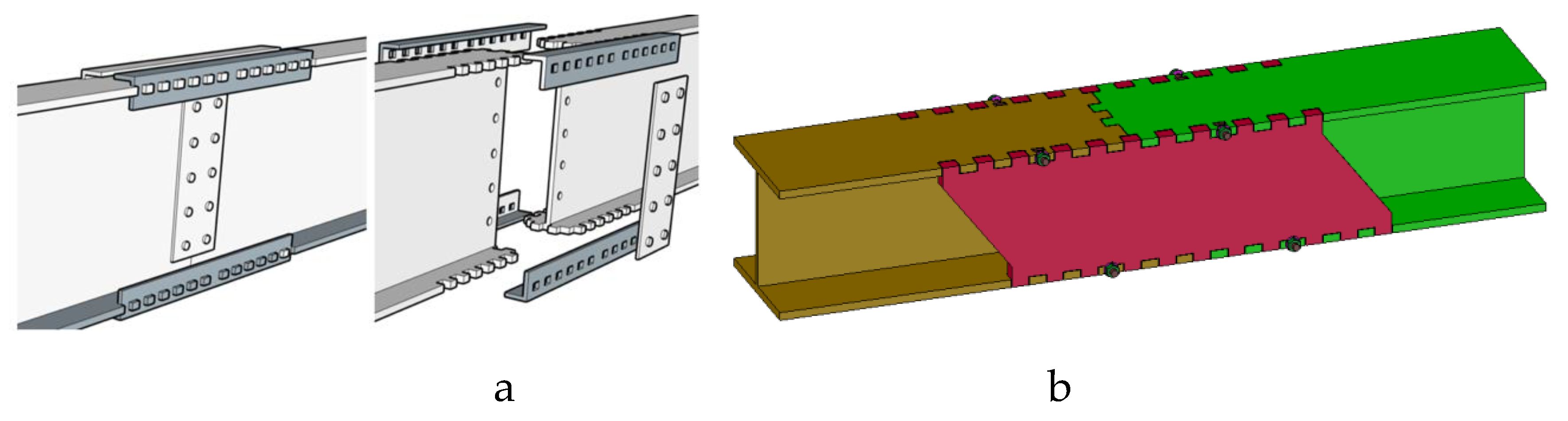
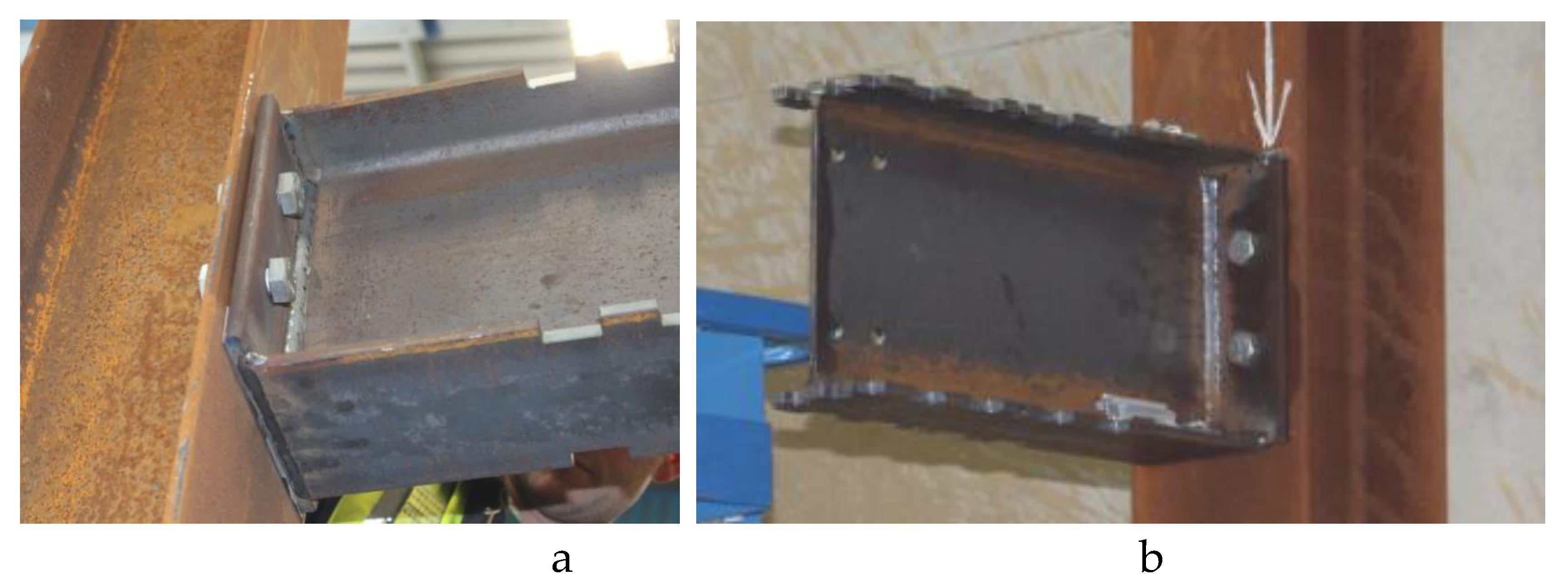
While more recent connections have been proposed such as the ConXtech connection [
9] (
Figure 1a), the Kaiser connection [
9], and the ATLSS connection [
10], to date they remain limited in use due to high costs, difficulties in manufacturing or installation, and/or lack of adaptability to the various connection needs across the structural steel industry. Of all the systems mentioned above, only ConXtech is commercially available but is marketed strictly as a beam-to-column connection. The connection relies on a combination of bolts and accurate machining and cutting to provide overall savings gained from faster on-site assembly [
11].
Another promising technique is the use of adhesive bonding in structural steel connections. One study [
12] showed that the application of adhesives in steel construction is possible as a stand-alone solution or in combination with bolts. More recent research in this direction [
13,
14] was directed towards selecting the appropriate adhesive and its application to steel overlap connections. A useful closed-form solution for the peeling and shearing stresses in polymeric adhesively bonded structures is presented in [
15], where it was intended to be used for the design analysis and exploration of such connections by practicing engineers. However, the use of adhesives bonding in structural steel connections is still at an early stage of development. Major questions related to fire resistance and ductility need to be answered before a wide-scale application would be possible.
The history of metal connections demonstrates that the main drivers for change are technological advancements that offer better economy and new requirements for erection speed. Arguably, recent advances in manufacturing offer elements of both, along with additional functional advantages, as will be described in
Section 3. A brief overview of steel cutting methods is provided in the following section.
2.2. Current Advanced Steel Cutting Methods and Affiliated Technologies
Saws and oxy-fuel are the traditional structural steel cutting methods. They are mostly applied manually, which results in highly variable speed and accuracy depending upon the relative skill of the tradesperson. The introduction of computer numerical control (CNC) technology and robotic arms in conjunction with more advanced coping methods (e.g., plasma cutting, laser cutting, waterjet, wire electrical-discharge machining (WEDM)) overcome these disadvantages and enable precisely shaped steel cuts to be produced more accurately, rapidly, and consistently than previously possible. Other methods, such as milling and machining, are used in specialist applications. These advances in cutting technologies allow the shaping of steel with unprecedented precision, repeatability, scalability, and economic efficiency. Furthermore, their coupling with robotic-arms offers new options for 3D fabrication that are only beginning to be explored.
2.2.1. Laser Cutting
Laser cutting focuses a high power laser beam to heat and melt steel. Cutting gas is applied to both cool the focusing lens and remove the molten steel waste. The technology works to thicknesses of about 40 mm in steel and produces precise geometries, but at a slower speed and higher operating costs compared to plasma cutting, particularly as material thickness increases [
16].
2.2.2. Plasma Cutting
With plasma cutting, a high temperature ionized gas arc is used to melt the steel and remove the molten waste. High-end plasma cutting differs from normal plasma cutting by its focused arc. This is achieved by the introduction of a swirl gas in addition to the plasma gas, which makes the plasma arc narrower, more stable, and having higher energy density than normal plasma. This process covers a wide range of material thicknesses from 0.5 mm to 160 mm. Though the capital costs are higher than conventional plasma cutting, they are much lower than laser cutting [
16].
2.2.3. Waterjetting
In waterjetting, a thin stream of water under high pressure is combined with an abrasive slurry to cut the steel by means of erosion [
17]. The waterjet has the advantage of being able to accurately cut steel members up to 100 mm and having no heat affected zone [HAZ] [
18]. However, cutting speed is typically slower than both laser and plasma cutting [
19]. Furthermore, integrating waterjet technology into a typical steel fabrication production line is difficult due to the presence of water.
2.2.4. Wire Electrical-Discharge Machining (WEDM)
In WEDM a wire of brass, molybdenum, or tungsten is continuously fed through the workpiece, while a dielectric fluid (typically deionized water) fills any gap between the wire and the workpiece [
20]. An electric current is passed through the wire to create a spark between the wire and the workpiece through the dielectric fluid. Each spark results in some erosion in the workpiece and the wire. As such, the wire must be fed continuously to prevent breakage. The main cutting variables are the wire, its diameter and feeding speed, the voltage, current, frequency, and fluid type. Current equipment automatically feeds the wire and controls its inclination by controlling the position of the upper and lower guides.
2.3. Tolerances: Manufacturing and Erection of Structural Steel
All manufacturing and erection processes work within their respective tolerance ranges. The term tolerance refers to the permissible range of variation in an object’s dimensions. A manufactured item cannot be produced to exact design dimensions but, instead, is manufactured within a set of tolerances that must be set so as to not negatively affect the function or appearance of an item. The actual dimensional deviations will depend upon a manufacturing method’s accuracy and quality control. If a manufactured item is composed of smaller parts, then all components must be manufactured to a tolerance such that the interfaces of the components will not compromise the whole. There are many sources of dimensional deviations in steel structures. These can be summarized as follows:
Section manufacturing. These are specified in national and pan-national standards such as EN 10034 [
15] in the European Union (EU) and the American Society for Testing and Materials (ASTM) A 6/A 6M-07 [
21] in the USA. As an example, for typical Universal Beam (UB) and Universal Column (UC) steel sections used in Ireland and the UK in standard buildings, with section heights not more than 400 mm and section widths not more than 325 mm, the section height manufacturing tolerance can be +4/−2 mm, and the section width tolerance can be +4/−4 mm. The section out-of-square tolerance is 2% of the width with a maximum of 6.5 mm. The manufacturing tolerance on straightness is 0.15% of the member length. For example, a member 7500 mm long can be out of straightness by 11.25 mm. Similarly, the section height manufacturing tolerance can be +4/−3 mm, and the section width tolerance can be +6/−5 mm, for typical W steel used in the USA in standard buildings, with section heights not more than 310 mm. The section out-of-square tolerance is 6 mm, and the manufacturing tolerance on straightness is 0.1% of the member length.
Cutting. These are specified in national standards and codes of practice such as the National Structural Steelwork Specifications for Building Construction [
6], EN 1090-2 [
22], and ANSI/AISC 303-16 [
23]. These tolerances are considered to be within the capability of all steel fabricators.
Cutting tolerance classification is usually specified according to the international standard ISO 9013 [
24]. This standard is applicable mainly to thermal cutting (laser and plasma) but can also be applied to waterjet cutting and WEDM. Five tolerance ranges are specified with Range 1 (best) and Range 5 (worst). For example, cutting a 10 mm plate to satisfy Ranges 1–5 will result in a deviation (or perpendicularity) of 0.08 mm, 0.22 mm, 0.50 mm, 1.0 mm, and 1.55 mm, respectively. WEDM can easily achieve Range 1. The best laser and waterjet cutters can also achieve Range 1, however the best plasma cutters can only achieve Range 2 or 3.
Site erection: A key factor for a successful erection of the steel building is the correct location of the first lift columns, which depends on the anchor bolts that connect the columns to their reinforced concrete foundations. The erection tolerance of the column horizontal base position in Ireland and the UK is ±10 mm. The equivalent tolerance in the USA is similar for anchor rod diameters between 25 and 38 mm. Bolt position adjustment is achieved through a combination of oversized anchor bolt pockets; oversized base plate holes and plate washers; and post-fixed anchor bolts. In a typical bolted connection with normal-sized bolts, the bolt-hole diameter is usually 2 mm larger than the bolt, for bolts not larger than 24 mm in diameter (22 mm in the USA). The resulting gap allows for some adjustability of the steel member locations. When more adjustability is required, slotted holes and shim plates can be used. All of these aspects, as well as the ambient temperature, contribute to the erection tolerances.
3. Intermeshed Steel Connection (ISC)
Capitalizing on advances in digital manufacturing to accelerate on-site structural steel assembly and addressing some of the disassembly issues, a new concept in gravity-resisting steel connections entitled the intermeshed steel connection (ISC), is proposed herein; a brief description of the concept was previously presented as a conference paper [
25]. The fundamental concept of the ISC is to replace existing field connections with those that are easier and faster to assemble. This is done through an arrangement of interlocking pieces that involve simultaneous, bi-directional meshing and load transfer (
Figure 1). One direction of meshing is achieved in the horizontal plane at the upper and lower flanges through fingers cut from the flange. The other meshing direction is achieved in the vertical plane through the cutting of the web. In all cases, the meshing is achieved by using state-of-the-art manufacturing techniques to precisely cut the ends of each steel member that is to be connected. Force is transferred at multiple surfaces primarily through bearing. No intermediary piece is needed. After positioning the members, the connection can then theoretically be locked, as will be explained below.
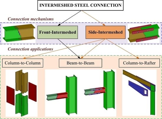
Geometric modifications of the bi-directional meshing concept are employed to address manufacturing complexities, assembly tolerances, and different levels and types of loading for specific applications including beam-to-beam, column-to-column, and portal frame connections where a column (i.e., stanchion) is attached to a rafter (
Figure 2). In this last instance, the intermeshed steel connection is designed to accommodate large bending moments, as well as shear and axial forces. The connection can also be used in a stub-out or “Christmas Tree” arrangement [
26] where multiple, short beam stubs have been affixed to a beam via welding or bolting in the fabrication shop, and the beam is then inserted in the field between the two column stubs. Finally, there is the option for the ends to be manufactured separately and then shop-welded to any standard section, thereby enabling the entire structural steel industry to use this connection without every fabricator having to own robotic cutting equipment. The ISC was conceived to provide a new path to develop a class of universal and scalable connections for both buildings or other structures.
As an evolution to the full bi-directional meshing, a simpler, one-directional option was designed,
Figure 1b. This connection can be seen as a transition from traditional, fully bolted connections to the ISC concept of no bolting. In this instance, the use of a web splice plate provide a simple means for transferring shear force—supporting the beam during assembly and allowing easier adjustment of the beam position. This can be achieved easily, as the number of bolts used in web splice plates is small relative to the number required for a flange splice plate. The two main variations of the ISC are: (1) front intermeshed (
Figure 1a) and (2) side intermeshed (
Figure 1b). These are described below in
Section 3.1 and
Section 3.2. In both instances, small manufacturing-based gaps are expected between the connected parts to allow a degree of adjustability.
3.1. Front Intermeshed Connection
The front ISC version was envision to minimize component parts (
Figure 1a and
Figure 3). The connection was designed for load transfer to occur directly through both the web and flanges. In the web, happens through bearing at multiple contact points along the stepped, high precision cutting. In the flanges, this is done via precisely cut fingers with flared ends. Specifically, the distal part of each finger is wedged to maximize three-dimensional (3D) inter-meshing (
Figure 3a). Once the members are properly positioned (
Figure 3b), a specially designed locking mechanism could be added across the webs of the connecting members (
Figure 3c,d). Although the connection was intended to resist gravity loads only, a lock could provide robustness and protect against unseating in the case of uplift or unexpected lateral loading at the connection point. In such an instance, disassembly would be achieved by removing the locking pieces and then lifting the steel pieces apart. Presently, only testing with a simple bolted plate has been undertaken.
The front ISC connection was conceived to allow rapid assembly and short hook time but requiring precise cutting of the flanges with only small allowable manufacturing tolerances as achievable with plasma or laser cutting. High precision cutting is needed to mobilize the bearing and shear load transfer through the wedge action, and the required small erection tolerances demand strong, on-site quality control, which are not always possible. The structural performance of the front ISC was found to lack sufficient ductility and strength (See
Section 4.1). To address those scenarios and to improve both the connection’s strength and the ductility, the side ISC was developed (See
Section 3.2).
3.2. Side Intermeshed Steel Connection
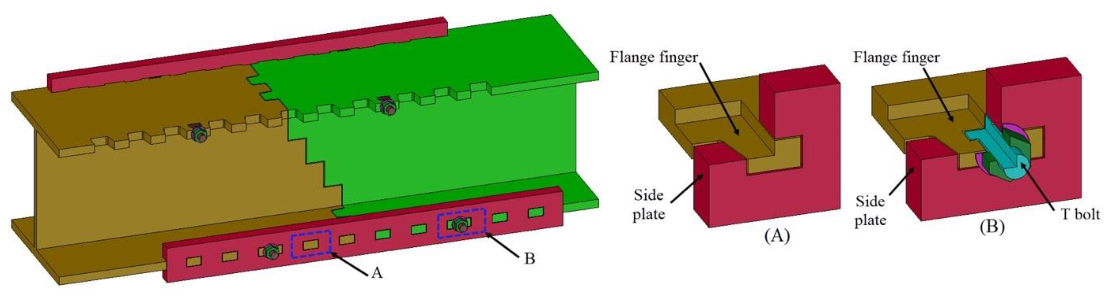
To accommodate larger tolerances in manufacturing and/or erection, the side ISC arrangement was devised (
Figure 4). Higher tolerances require more “play” in the connection to ensure contact between the fingers. Larger tolerances reduce the amount of available contact surface through which load transfer occurs. These larger tolerances are achieved through the introduction of a set of side plates at both the upper and lower flanges. In this arrangement, there are fingers at one of the member’s ends and also along the flange’s sides (
Figure 4a). However, unlike the fingers in the front ISC, those on the side ISC do not flare at the distal ends. Also, in this arrangement, side fingers both secure the side plates and transfer the load through multiple bearing faces, while those at the front aid only in placement and maintaining lateral connectivity and stability. Load is also transferred through bearing at multiple contact faces in the web through the stepped profile of the web. In practice, the side plates can be affixed using a variety of methods, such as locking pins or spring locks. The method shown in
Figure 4 uses T-head bolts. The bolt head is inserted in a compatible cut in a side finger (
Figure 4b). Then the side plates can be assembled. Finally, the t-bolts are affixed with nuts at the outer face of the side plates,
Figure 4c. Presently this arrangement with the t-head bolts has been tested only for constructability.
A feature that can be added is tapered finger edges with a small slanted angle,
Figure 5. This can offset the gaps between the flange fingers and the side plate holes caused by manufacturing tolerances. Other variations of the connections can be used. These include a bolted web splice plate instead of the multiple web contacts, as discussed earlier in this section. Furthermore, side angles can be used as an alternative to side plates,
Figure 6a, or full-depth side plates,
Figure 6b. In that case, the side plates/angles do not protrude above the top flange. This arrangement can be used when the top flange directly supports a slab.
The side ISC can be produced through multiple technologies. While cutting the flanges and web requires a multi-axis robotic arm and a plasma or laser cutter, the side plates or angles are relatively small and are, thus, producible via any simple flat-bed cutter with plasma, laser, or water-jet cutting.
3.3. Accommodating Tolerances
As discussed in
Section 2.3, steel structures are made with consideration of manufacturing, fabrication, and erection based dimensional deviations. The normal practice of erecting steel structures using bolted site connections requires careful adjustment of the interface between the steel columns and their reinforced concrete foundation. Once the columns are accurately positioned, the beams will fit between them. As discussed in
Section 2.3, steel members have different geometric deviations resulting from steel members manufacturing and cutting. These deviations are accommodated during the erection of the structure by the presence of a small amount of adjustability in the site bolted connections. Specifically, each bolt hole is 2–3 mm larger than the expected bolt diameter. There are three means through which the erection of a traditional structural steel connection is accomplished: (1) adjustability at bolt locations, (2) keeping the connection bolts untightened until the alignment of the members is finalized, and (3) using a podger spanner to align the holes at the points of connection.
In contrast, with the front ISC, the only possibility to accommodate dimensional variations is by providing sufficient gaps between the fingers. However, such gaps will reduce the structural performance of the connection, as they will result in reduced steel remaining in the intermeshed fingers. Consequently, the front ISC connection cannot accommodate much adjustability and, thus, requires accurate control over the section geometry, member straightness, and end cutting precision. Hence, deployment of the front ISC is limited to where the required precision is achievable.
In contrast, the side ISC was envisaged from the start of its development to allow for larger adjustability without significantly affecting structural performance. In a similar fashion to using bolt holes that are larger than the bolts themselves, the holes in the side plates (or angles) of the side ISC can be made larger than the flange fingers. The horizontal dimension of the holes can be increased to allow for more tolerance in the member length direction. Vertical hole expansion is also possible where needed. Such cases can be encountered when the section depth and/or the section out-of-square of the two connected members is different due to manufacturing deviations. Furthermore, tapered fingers with matching tapered holes allow for easier assembly. In this case, the mating surfaces will have relatively large gaps when the side plates are aligned to be pushed onto the fingers. The gaps will reduce, as the side plates approach final positioning.
The typical, non-preloaded bolted connection usually works by transferring the connection forces through shear. This requires the connected parts to move relative to each other to achieve contact with the bolts. The resulting slip manifests itself in initial structural deflections and movements that will develop during construction. In typical steel structures, such deformations can be counteracted by pre-cambering the members. Similarly, a side ISC can also be pre-cambered to counteract the initial deflections and slip likely to occur due to the gaps between the contact surfaces.
4. Connection Structural Performance
The relevant ISC design principles are described in this section. As previously mentioned, the ISC transfers load through multiple bearing surfaces. With the front ISC connection, the tensile load is transferred in the flange by bearing and friction. While the load in the fingers is mostly axial, there is some bending moment due to the lateral deformation of the fingers. In contrast, in the side ISC, the load path into the flange is through the side finger interface with the side plate. The side fingers need to resist both the shear force and the bending moment resulting from the load. The side plate is mainly subjected to axial load from the fingers. If the finger/side plate interfaces are located at the centroid of the side plate, then there is no secondary moment, and the side plate resists the load by pure axial tension. However complicating factors such as the changing finger/side plate interface geometry that may result from usage-based deformations and shear forces transferred through the side plates at large levels of displacement of the steel member can add secondary moments and shear stresses to the side plates. The connection’s structural performance has been studied through many numerical and physical experiments as described in the following sections.
4.1. Small-Scale Testing of Front ISC Flange
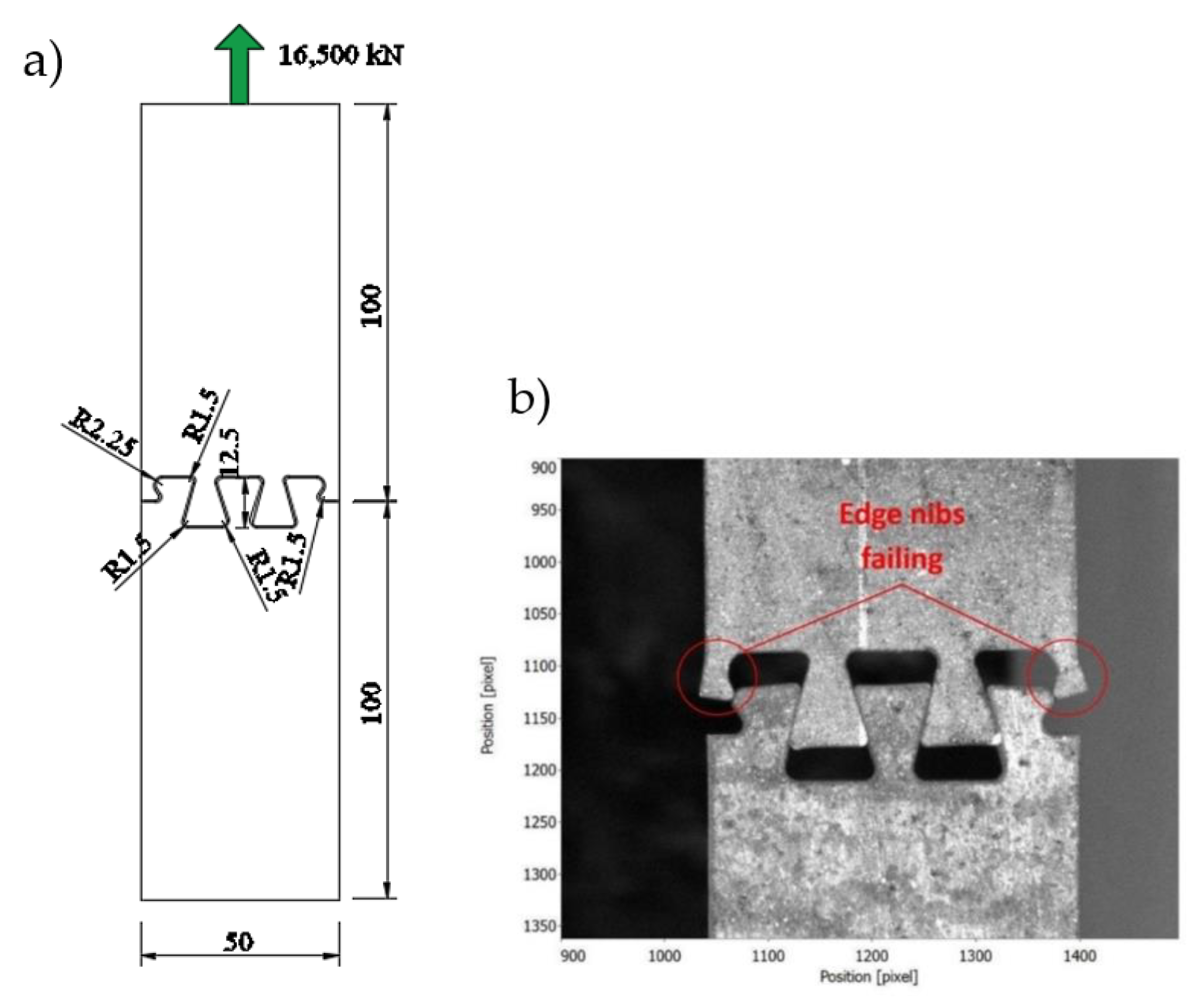
A small-scale sample of a front ISC (50 mm wide) was cut with a waterjet cutter from a 6 mm thick S275JR steel plate. The geometry of the tested sample is shown in
Figure 7a. A close-up to the plate interface is shown in
Figure 7b. The test was conducted at Queen’s University Belfast.
A Zwick/Roell RetroLine tC II universal testing machine (UTM) was used. It has a tensile capacity of 100 kN with an accuracy of ±2% and crosshead speeds of 0.001 mm/min–1000 mm/min. Tinius Olsen mechanical wedge action grips were used to hold samples in place. The applied displacement rate was 1 mm/min. Force was measured by UTM load cell, while displacements were measured using a LaVision StrainMaster Portable Digital Image Correlation System.
The test load-displacement curve,
Figure 8, shows an initial slip of 1 mm with a small resistance of around 1.6 kN. This was followed by nearly perfectly elastic behavior up to 17.9 kN when limited yielding occurred. This was followed by a small strain hardening region up to an ultimate load of 19.3 kN. Afterwards, there was a drop in resistance, a slip, and then a nearly linear resistance drop. Resistance was completely lost at around 12 mm of displacement.
The load-displacement curve illustrates a few important aspects of the front ISC behavior:
The initial slip of nearly 1 mm was a result of the gaps between the contact surfaces. The gap allowed by the design was 0.6 mm to ensure the fit. Considering the manufacturing tolerance of ±0.3 mm, the total resulting gap can be between 0.0 mm and 1.2 mm.
Following the initial slip, the behavior was nearly linear. This indicates that the majority of contacts were established at nearly the same time and that the steel cutting was executed in an accurate manner.
After reaching the peak load, the connection could not maintain that resistance for long. This means that the front ISC can be used for locations where behavior is elastic.
The yield load was 22% of the of 82.5 kN full section yield load. If the connection is assumed to be located at the beam flanges, then the peak resistance would be around 22% of the full section resistance.; quite small to be considered as a moment connection. The connection should, thus, according to EN 1993-1-8 strength classification be categorized as a nominally pinned joint [
27].
If the connection is assumed to be located at the beam flanges, then the stiffness classification as per EN 1993-1-8 can be considered as a semi-rigid joint, if a nominal beam 100 mm deep, 2500 mm long was assumed [
27].
These test results confirmed that the front ISC cannot be used as a moment connection due to its low moment resistance and inability to maintain that resistance for large displacements (or rotations). A front ISC might be usable to improve the serviceability (rather than the ultimate) limit state behavior; for example, to reduce live load deflection by providing some level of continuity without employing extensive site bolting. However, concerns about the connection ductility, as described in iii above, need to be investigated further, before such an application can be considered.
4.2. Side ISC Beam Test-2
A 3658 mm (12 ft) W18 × 46 beam with a side ISC was tested with combined bending and shear effects. The connection was located at mid-span, while the load was applied 914 mm from the support. The beam was made of Grade 50 steel. Steel angles (rather than plates) were used for the side ISC. The four angles were 63.5 × 50.8 × 9.5 mm (2
½ × 2 × 3/8”), unequal angles made from A36 steel. Bolted shear splice plates with dimensions of 368.3 × 158.8 × 6.4 mm (14.5 × 6.25 × 1/4”) were used to connect the two webs. The test arrangement was as shown in
Figure 9. The test was conducted at the University of Minnesota. An MTS 2650 kN load frame located in the Galambos Lab. Force was measured with a UTM load cell. Displacement was measured by two string potentiometers, which were attached to each beam flange approximately 25 mm from the connection centerline. The applied displacement rate was 2.3 mm/min (0.09”/min).
The beam flanges were cut with a Python X Robotic CNC plasma cutter, while the angles were cut with an OMAX A-Jet waterjet cutter. A tolerance of 1.6 mm (1/16”) was specified. The average measured cutting deviations for the beam top and bottom flange tooth width were 1.00 mm (0.039”) and 0.74 mm (0.029”), respectively. The maximum difference from the theoretical values and standard deviation for the top flange were 1.38 mm (0.054”) and 0.21 mm (0.008”), respectively. The corresponding values for the bottom flange were 1.15 mm (0.045”) and 0.26 mm (0.010”). The average width deviation, maximum deviation, and standard deviation in the angle hole width were 0.556 mm (0.005”), 0.65 mm (0.0125”), and 0.045 mm (0.0018”), respectively. All values were within the specified tolerance. Notably, the accuracy of the waterjet cutting of the angles was better than the plasma cutter.
The tested beam was loaded with a single point load at its one-quarter span. The beam had a calculated plastic moment resistance of 512.5 kN m (377.9 kip-ft), based on a yield stress of 344.7 MPa (50 ksi). The point load producing this moment was calculated as 747.3 kN (168 kip). A connection at the beam’s mid-span was designed to carry nearly one-third of the plastic moment resistance of the steel section or 170.8 kN m (126 kip-ft). Each of the two angles was designed to reach its elastic limit at 176 kN (39.6 kip) based on a yield stress of 248.2 MPa (36 ksi). The calculated beam load that would produce yielding in the two angles was 374 kN (84 kip) based on an angle yield stress of 248.2 MPa (36 ksi) and assuming no flexural contribution from the web shear splice plates.
The load-displacement curve is shown in
Figure 10. The peak load was 810 kN (182 kip). This load corresponds to a beam maximum bending moment of 555.6 kN m (409.8 kip-ft), and a connection moment of 370.4 kN m (273.2 kip-ft). These values were based on a measured yield stress of the beam flange of 379 MPa (55 ksi).
The load-displacement curve illustrates a few important aspects of the side ISC behavior:
An initial deflection of nearly 13 mm (0.5”) was observed at the start of the test to close the gaps between the contact surfaces. Most of this deflection was established at the small load of 13 kN (3 kip)–less than 2% of the peak load. As mentioned earlier, the side angle holes were fabricated to be 1.6 mm (1/16”) wider on the two vertical faces. A simple calculation based on the actual average gaps between the connection fingers and the holes predicted a slip of nearly 9.6 mm (0.4”) which is close to the actual value of 13 mm (0.5”). The ability to estimate the initial deflection adds to the predictability of the connection behavior.
Following the initial slip, the behavior was nearly linear. Similar to the front ISC example (see
Section 4.1), the majority of contacts was established at nearly the same time. The linear part of the load-displacement curve continued up until nearly 400 kN (90 kip). This load corresponded to a maximum beam moment of 274.6 kN m (202.5 kip-ft) and a moment at the connection location of 183 kN m (135 kip-ft). This load was nearly 7% larger than the calculated beam load causing yield in the angles of 374 kN (84 kip). This indicates that the shear splice plates shared some of the moment and/or that the yield stress of the angles was larger than 248.1 MPa (36 ksi).
Following the end of the linear load-deflection behavior, the connection started a non-linear increase in resistance up to a maximum load of 810 kN (182 kip) at a displacement of 70 mm (2.75 in). This indicates that the side ISC can maintain its resistance during large rotations.
The measured peak load 810 kN (182 kip) was larger than that causing the full section yield based on a plastic section resistance load of 747.3 kN (168 kip). This result indicates that steel overstrength of the side angles is an important influencing factor of the overall connection ultimate resistance. The connection can be categorized as a partial strength joint according to the EN1993-1-8 [
27] strength classification.
Based on the rotation calculated from the beam deflection, the stiffness classification can be considered as semi-rigid joint based on EN1993-1-8 [
27].
Shear force produced permanent vertical slip between the two beam flanges, resulting in the angles having an undulating post-test appearance (
Figure 11). As a result, the side angles carried, in addition to axial force, a combination of shear forces and secondary moments due to their unsymmetrical section. Furthermore, small lateral displacements were observed at the end of the test, which indicates that the beam may have been experiencing the onset of lateral-torsional buckling. The test results confirmed that the side ISC can be used to provide large moment resistance and continuity even at locations of large bending moments. The testing demonstrated the connection’s ability to provide predictable deflection behavior, controllable strength, and ductility, as well as being produced and tested with the design fabrication tolerances.
4.3. Side ISC Beam Test-B
A 1850 mm long beam made from 254 × 146 × 31UB section with side ISC was tested. The connection was located at mid-span while the load was applied as two point loads around mid-span. The beam was made of S355 steel, while the two side plates were made from S275 steel. The test arrangement and the connection details were as shown in
Figure 12.
The beam flanges were cut with a Voortman V808 robotic thermal cutting machine with a plasma cutter. The same machine was used to cut the side plate holes. A tolerance of 2 mm was specified for the manufacturing of the beam and side plates. The average measured deviations for the beam and angles was 2.8 mm and 2 mm, respectively. The plasma cuts were not straight and suffered from large irregularities and deviations,
Figure 13.
The connection was designed to fail at the side plates. Using the side plates’ yield stress of S275 and ultimate stress of 410 MPa, the calculated test beam yield and peak loads were 160 kN and 239 kN, respectively. Both of these loads were smaller than the load able to produce yielding in the steel section. The beam load needed for the full UB steel section to reach its plastic moment resistance was calculated as 319 kN and that of the reduced section due to the flange cuts was 268 kN; both based on yield stress of 275 MPa.
This test was conducted at the University College Dublin structural lab using an Instron 1274 modified frame. The force was measured with a UTM load cell. The displacements were directly measured from the UTM load cell movement. The applied displacement rate was 3 mm/min. The load-displacement curve is shown in
Figure 14. The test was stopped after reaching the loading limit of the test machine of 253 kN. The attained peak test load of 253 kN corresponded to a side plate stress of 435 MPa, which is slightly larger than the expected ultimate stress of 410 MPa for the S275 steel. The side plates started to yield at that load (
Figure 14).
The load-displacement curve illustrated a few important aspects of the side ISC behavior:
An initial low stiffness behavior was observed at the start of the test. The deflection at 5 kN (nearly 2% of the maximum test load) was 3.5 mm. However, the stiffness started to increase until a maximum value was reached at nearly 6 mm of deflection. The slow stiffness increase was attributed to the rather inaccurate cutting of the steel beam and side plates. This resulted in small contact zones between the flange fingers side plates at low load levels. As the load increased, the contact zones increased due to local plastification, which resulted in greater stiffness. Importantly, the manufacturing deviations did not affect the overall connection resistance.
Following the initial stiffness gain in the load-displacement curve, a linear relationship continued to nearly 165 kN. This load corresponded to the yield load of the side plates. A reduced stiffness behavior followed this stage up to 253 kN.
The peak load of 253 kN was slightly smaller than the reduced plastic UB section resistance of 268 kN and that of the full section of 319 kN. The connection can be categorized as a partial strength joint according to EN1993-1-8 strength classification [
27].
Based on the rotation calculated from the beam deflection, the stiffness classification can be considered as a semi-rigid joint based on EN1993-1-8 [
27].
The test results confirmed that the side ISC can be used to provide the required moment resistance even with manufacturing inaccuracies. The connection strength was not significantly affected by such inaccuracies. However, the stiffness was reduced due to the smaller contact area between the flange fingers and the side plates.
4.4. Test Frame Assembly
As the ISC was intended as an alternative to site-bolted and site-welded connections for frame assembly, constructability is an important factor. Unlike site welding and bolting there is not a body of experience in the industry for the detailing, fabrication, and erection of steel frames with respect to constructability and the effects of manufacturing and site tolerances (
Section 2.3) on the frame erection for these types of connections. To begin to address these questions, a frame-assembly test was conducted.
The main goal was to test the level of ease and duration requirements of a frame erection using the ISC. The secondary goal was to establish the viability of disassembly. The frame shown in
Figure 15 was designed to represent a two story building where the effects of fabrication and erection deviations at one location necessarily impact all other locations. The frame’s center-to-center width was 3681 mm, and the total height was 5000 mm.
The fabrication deviations were selected to represent some of possible values within the allowable fabrication tolerances of the steel industry. The same concept was applied to the erection deviations. In all cases, the cumulative deviation effects were arranged to produce the most severe overall deviations.
The frame was made from 152 × 152 × 30 UC columns and IPE270 beam sections. Two short stub beams were bolted to the columns at mid-height and top levels. These were used to connect the two beams at these levels. A total of four side ISCs were required to assemble the frame (
Figure 16). The frame assembly/disassembly was conducted according to the following steps:
Step 1: Assembly of frame with perfect geometry
Step 2: Disassembly
Step 3: Introduction of geometric deviations
Step 4: Reassembly of frame
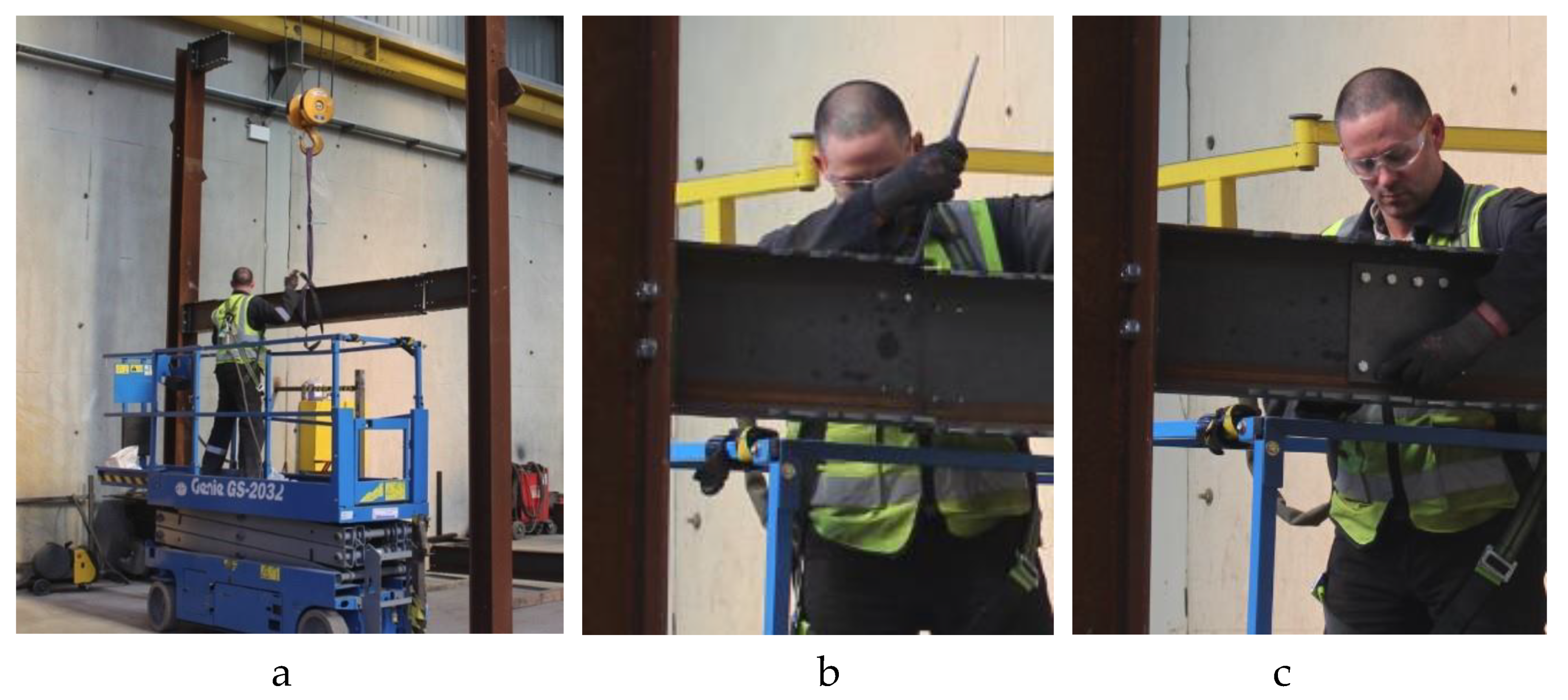
The following is a brief description of the four assembly/disassembly steps. The frame assembly, Step 1, started with erecting the two columns, then connecting the four stub beams,
Figure 16. This was followed by placing level 1 beam into position and bolting the web splice plates,
Figure 17, then connecting the side plates,
Figure 18.
The same procedure was followed for the level 2 beam. Prior to this documentation, the erector was given the chance to try assembling the ISC only twice. In spite of the lack of significant experience with the ISC, the erection progressed well and without difficulties.
The final frame was then disassembled, Step 2, and geometric deviations were introduced as follows:
Column level: this deviation was introduced by adding a 10 mm shim plate under one column base,
Figure 19.
Stub beam angular deviation: this deviation was introduced by inserting a 1 mm-thick shim plate at the bottom end of the first level stub beam on side (a) of the frame, hence creating an upwards kink,
Figure 20a. This geometric deviation added to the upwards end movement due to the raised level of the column on this end by 10 mm (see above) relative to side (b) of the frame.
Similarly, a 1 mm thick shim plate was inserted at the top end of the first level stub beam on side (b) of the frame (
Figure 20b), hence creating a downwards kink. A schematic of the effects of the introduced deviations is shown in
Figure 21. The frame was assembled again (beam level 1 only),
Figure 22. The erection progressed faster than the initial erection of Step 1, despite the presence of the lower level of frame alignment due to the introduction of the shim plates.
The frame assembly test illustrates a few important aspects in relation to the erection using the side ISC:
The assembly analysis indicated a fast learning curve with the time required to complete one side ISC progressively improving from 12:58 min initially with an average of 12:06 min for the first two connections to a final average of 4:32 min for the last two connections.
The introduction of geometric deviation did not cause any delay in the frame erection.
The deviations introduced in this test need to be followed by further studies covering more scenarios of deviations including actual, on-site erections.
5. Discussion
The intermeshed steel connection was developed to create a new type of connection that leverages advances in digital manufacturing to increase automation and efficiency. The connection concept was developed to be scalable, versatile, and adoptable in three important ways: (1) applicable to any member size, (2) applicable to a wide range of connection scenarios, and (3) producible by several cutting methods.
The side ISC provides larger strength and ductility when compared to the front ISC. The side ISC also has more ability to accommodate large manufacturing geometric deviations without significantly affecting its strength. The connection assembly of the plate and beam tests was straightforward, and no difficulties were encountered.
The side ISC was adopted in a two story steel frame to test the construction and deconstruction speed and the ability of the side ISC to accommodate site tolerance. The test results indicate that all these goals can be achieve with relative ease. The erector’s learning curve was fast, with substantial performance improvements recorded after gaining experience in the assembly and disassembly of the side ISC.
Manufacturing of the ISC was conducted using a multi-axis robotic plasma, laser, and waterjet cutters. The available technology in this regard was found to be adequate to manufacture the required geometry of the ISC. All three steel-cutting technologies managed to produce good results. However, in one case of plasma cutting, the measured cutting deviations were larger than what was specified. The experience of the authors regarding the manufacturing of the test samples is that achieving the required design tolerances is possible but requires coordination with the steel fabricators to calibrate and adjust their machines to achieve the specified cutting precision.
As the ISC does not have decades of documented testing, multiple numerical models, and extensive experience in its design, detailing, and erection (unlike bolted and welded connections) history, significant future effort and investment beyond the fundamental initial testing that was conducted at University College Dublin, Queens University Belfast, and the University of Minnesota is likely to be needed. Furthermore, the introduction of the ISC and similar connections using advanced manufacturing to the construction industry will require a willingness across the construction industry from clients, designers, fabricators, and contractors to adopt it. The main value for the clients is that the structure can be made more economical and available sooner due to a reduced erection schedule, with the additional potential benefit of possible future disassembly. However, evidence of the potential cost savings needs to be demonstrated. A small-scale frame assembly test was conducted, however, a large-scale test assembly or clients willing to take the risk of using a new system will be needed. Other issues such as the potential disassembly difficulties resulting from service loads or the presence of shear studs need to be studied.
6. Summary and Conclusions
A new steel connection method is proposed to allow for more automatic fabrication and fewer bolts at site connections using currently available robotic plasma, laser, and waterjet cutters. Two configurations of the ISC were developed and studied. The first, the front ISC, has the advantages of having a small number of additional parts and rapid assembly. However, this connection requires more precise cutting of the flanges and has limited ability to accommodate site misalignment. Furthermore, the test results confirmed that this connection cannot be used as a moment connection due to its low moment resistance and ductility.
The second connection configuration, the side ISC, has more parts. However, the test results indicate that this connection can resist much larger moment than the front ISC and has substantially more ductility. The limit of this moment resistance is the reduced steel section after cutting the side fingers. Furthermore, the side ISC has more ability to accommodate manufacturing and site geometric deviations.
From a stiffness perspective, both the front and side ISC can be classified as semi-rigid joints according to the EN1993-1-8 stiffness classification. Furthermore, both ISC connections have initial low stiffness resulting from the movement of the connected parts until contact is first established between the connected parts. This behavior is similar to that of a non-preloaded, bolted connection.
Structures with these connections can be easy to assemble and to deconstruct without damaging the steel and, thereby, provide better opportunities for reusing steel rather than just recycling. Arguably, the ISC will also provide an incentive for steel-cutting manufacturers to improve their current technology, which will result in overall improved efficiency and more economical structures. Where sufficiently precise digital manufacturing options are not available locally, precisely cut ends can be manufactured separately and shop-welded to standard sections. While not as cost-effective, this would enable the steel industry to benefit widely from this new connection without requiring retooling by every fabricator.
Since the ISC will not be initially covered by a design code, its acceptance would require extensive testing and numerical analysis to establish the expected performance of the connection, along with a simple design method based on current code principles. A series of publications with the results obtained from the three methods: physical tests, numerical tests, and simple code-based design will be forthcoming to help provide the basis for widespread acceptance of the proposed intermeshed connection.
Based on the experimental test results, the structural performance of the connection proved to be predictable, consistent, and scalable. The connection was shown to be able to be designed to provide a reliable performance range from a nominally pinned joint to a partial strength joint exhibiting semi-rigid behavior. The connection also proved constructible in experimental frames with and without geometric deviations. Unlike previous novel connection methods, the ISC can be applied to beam-to-beam, column-to-column, column-to-rafter (portal frames), and dismountable arrangements. As such, the ISC offers opportunities to make steel construction a more efficient 21st-century industry that encourages reuse rather than recycling.


 ,
, 