Article

Integrated Cost-Analysis Approach for Seismic and Thermal Improvement of Masonry Building Façades

1
Department of Energy, Systems, Territory and Constructions Engineering, University of Pisa, 56100 Pisa, Italy
2
Steel Project, 57121 Livorno, Italy
3
Department of Civil, Environmental Engineering and Architecture, University of Cagliari, 09123 Cagliari, Italy
*
Author to whom correspondence should be addressed.
Buildings 2020, 10(8), 143; https://doi.org/10.3390/buildings10080143
Submission received: 26 June 2020 / Revised: 8 August 2020 / Accepted: 11 August 2020 / Published: 18 August 2020
(This article belongs to the Section Building Structures)

Abstract

:
The combination of structural and thermal efficiency is a new frontier in civil engineering. Indeed, the retrofitting strategies should optimize costs and technical solutions from these two points of view. If a technical solution is able to provide an improvement of both structural and energetic behavior, then the utility of the intervention can better justify the economic investment. In this paper, a meso-scale approach (i.e., façade-scale) for integrated interventions applied on masonry façades is proposed. The structural performance of the façade is evaluated by considering base shear and ductility of the structural element through non-linear static analyses. Moreover, the thermal indicator, that is the thermal transmittance, is computed with a simplified approach in terms of an equivalent wall, taking into account the role of the windows and doors of the façade. As proof of concept, the procedure is applied to a façade of an existing masonry building. Economic and environmental iso-cost curves are obtained to tune the interventions conceived for a real case study, analyzing the benefit offered by different retrofitting solutions.

1. Introduction

Nowadays, existing masonry buildings do not fulfill standards requirements in terms of seismic and energetic performances according to current regulations. In the past, masonry buildings were generally not designed to withstand seismic actions, due to improper vertical connections between walls and horizontal connections between more or less flexible diaphragms [1] or roofs and walls [2,3]. These aspects worsen the structural behavior in case of irregular in-plan buildings [4,5]. In addition, in some cases, the masonry texture is such that localized damages can occur, making this aspect extremely difficult to evaluate in a seismic analysis. For these reasons, it is necessary to adopt structural techniques, such as ferro-cement, reinforced plaster, grout and epoxy injections, steel plates, stainless reticulatus grids, FRP, GFRP [6], bionatural aggregates and others. These techniques improve the in-plane and out-of-plane behavior of masonry walls [7,8,9,10], either undamaged or damaged, giving a more monolithic behavior, greater strength and stiffness. Moreover, the level of knowledge of the material is a key aspect, and for that, only experimental and in situ tests can really be reliable [11,12,13]. As for the thermal aspect, as is well-known, masonry does not have high performance levels in terms of thermal insulation, in case of absence of insulating layers. Although insulating from the exterior side would provide optimum performance and would ensure the integrity of the masonry walls, in the case of historic stone buildings, the addition of new insulation is generally restricted to the interior side of the building for aesthetic reasons [14]. Nevertheless, stone masonry was recently studied, showing better performances than those normally expected [15]. However, common insulating techniques for masonry buildings are batt insulation, through fiberglass rolls, mineral wool, cellulose, polyurethane foam and polystyrene. Beyond the traditional techniques, it is worth mentioning ways of substituting polymeric elements or expanded clay in vibro-compressed units through bionatural aggregates (cork and hemp fibers) that can be more sustainable and improve the thermal response [16]. A further aspect is resistance in case of fire: in that case, the walls, showing interesting performances against fire [17,18] can be weakened by the insertion of reinforced concrete elements [19]. In this sense, the use of visual inspection strategies can support the designer in the choice of the optimal rehabilitation technique. Independently from the building material, since the establishment of various climate change acts (e.g., in UK in 2018, in 2019 in the Philippines), building regulations across the world have been imposing restrictions for their thermal performances. This drove public authorities and designers to find new solutions for sustainable building and retrofitting techniques. All the buildings, as any other engineering system, are subjected to gradual or sudden processes of deterioration [20], which is unfortunately generally neglected by the current studies of sustainability [21]. When considered, the retrofitting interventions influence the amount of greenhouse gases (GHG) emissions [22]. A recent work proposes a framework to investigate building energy performances through thermography techniques, building modelling, characterization of thermal bridges and future prediction for overheating [23].
An extensive state-of-the-art work about the traditional structural solutions can be found in [24]. Clearly, these techniques do not significantly increase the mechanical features of walls, and often structural interventions (e.g., FRP) have a low impact on their energy efficiency. It is interesting to investigate how the combination of structural and energetic improvement can quantitatively affect the overall performance of the building and costs. An interesting contribution to this topic is given in [25]. Referring to the response of a single masonry panel, in [22,23] well-known methods to separately investigate seismic and thermal analysis are properly combined to provide an evaluation method to optimize both aspects. Compared to these last contributions, in the present work, the method is extended to the entire façade of a masonry building. The proposed method takes into account the actual façade geometry including openings.
This work is inspired by two crucial aspects: integrated approach and sustainability. Integration means the combination of more processes, in this case, seismic and energetic improvement of buildings. A procedure in which only seismic (or energetic) retrofitting is believed to be restrictive and not able to understand the needs of modern society. An integrated intervention should also be sustainable, otherwise it loses its meaning. The sustainability consists of improving the structural response (e.g., static, seismic, energetic, acoustic, etc.) by optimizing economic and environmental costs and by respecting the social needs. It should be sought in the whole life-cycle of the construction (from erection to demolition), which is, however, disregarded in this contribution. In the life-cycle perspective, for example, more sustainable intervention in a new masonry building could be the use of bionatural components [16]: they can reduce the impact on the environment, do not sensitively decrease the material strength and improve the thermal insulation of the wall. The topic is urgent and impelling; indeed, as well-known, the building sector is responsible for 40% of energy consumption and generates 36% of GHG emissions [26].
In [27,28] six representative retrofitting techniques were considered to investigate the improvements in terms of thermal resistance, bending moment and shear structural strength. The need for using retrofitting techniques instead of demolishing and rebuild is relevant. Indeed, as it was shown in [29], it is more convenient to renovate an existing building than to demolish it and rebuilding a new one, if environmental impact is considered in a life cycle assessment. A cost-analysis was performed for plain walls discussing iso-cost performance curves, which combine seismic and energetic performance indicators. These curves were obtained at the micro-scale level, namely for the individual plain wall and considering, as a structural indicator, the bending resisting moment and shear strength of the wall. This paper proposes an evolution at mesoscale level (i.e., façade scale) of the methodology introduced in [27,28] and applies the procedure to an existing masonry building discussing the different implications of each assumption. It also gives practical recommendations on how to evaluate the level of improvement in an integrated way.
The three levels of investigation (single panel, single façade, entire building) can provide increased levels of information to decide the most appropriate retrofitting strategy.
Section 2 illustrates the integrated approach at a mesoscale level (i.e., the masonry façade), which is intermediate between the microscale level (i.e., the single masonry panel) and the macroscale level (i.e., the entire masonry building). Section 3 applies the procedure to a façade of a case study of an existing masonry building located in Italy. Section 4 defines the demand curves, discusses the results and generalizes them in a larger perspective

2. Integrated Approach at the Mesoscale Level

2.1. Procedure

The mesoscale approach proposed here consists in performing structural and thermal analysis on external façades of buildings, to evaluate the economic and environmental iso-cost curves resulting from the adopted interventions. The latter aspect has the purpose of understanding which type of intervention is optimal from a structural, sustainable and economic point of view.
The procedure consists of the following steps [Figure 1]:
  • Acquisition of the structural and thermal parameters needed for the analysis (mechanical parameters, such as tensile strength, shear strength, etc. and thermal parameters, such as thermal conductivity, thicknesses, etc.)
  • Definition of a set of integrated interventions, namely retrofitting strategies that have positive effects on either the seismic response, or the thermal performance or both of them.
  • Identification of a performance indicator at mesoscale level: as for the structural behavior, the variation of base shear capacity Δ V and the corresponding variation of ductility capacity Δ μ are considered, defined by well-known methods (non-linear static analysis); as for the thermal side, the variation of thermal transmittance Δ U is taken into account.
  • Economic and environmental iso-cost curves representing the relationships between the thermal capacity indicator ( Δ U ) and the structural capacity indicators ( Δ V or Δ μ ) . For each integrated intervention, after an economic budget (investment) or an environmental impact in terms of CO2eq are fixed, one can calculate, as explained in Section 2.2 and Section 2.3, the corresponding pair of capacity indicators. That represents a single point in the graphs Δ U Δ V or Δ U Δ μ . By varying the economic budget or the environmental impact, several points are obtained. Finally, the curves fitting these points can be regarded as iso-cost curves. Moreover, the iso-performance curves, that will be the subject of future work, will express, for the same seismic or energetic performance, the economic investment needed or the environmental impact caused by each integrated intervention.
  • Definition of dimensionless parameters c U and c R , defined in [28], to identify the demand for thermal and seismic performances respectively, with the expressions:
    c U   =   D D i D D m a x ;   c R   =   P G A i P G A m a x   ,
    where P G A i is the seismic peak ground acceleration at the site, P G A m a x is the maximum value in all the Italian regions (or any other reference zone in the world); D D i is the degree day value of the site and D D m a x the maximum Italian value. They are given for the different construction sites respectively by [30,31].
  • The hypothesis of a correlation between energy efficiency demand and seismic demand, through demand curves identified by these analytical expressions:
    Δ U =   α c U c R Δ V ;   Δ U   =   α c U c R Δ μ   .
They are based on a simple criterion of proportionality of increment of capacity indicators ( Δ U , Δ V or Δ μ ) with the demand indicators ( c U , c R ). As stated in [28], α is a corrective and tuning parameter that can be defined by the decision-maker according to political, social or stakeholder reasons. The values of this parameter α can be defined by using a short number of case studies that are assumed as emblematic to the political, social or stakeholder goals. The tuning parameter α should assume higher values in low seismic and high thermal demand areas. By contrast, in high seismic and low thermal demand areas, the α values may be lower. One can see α as an additional parameter that modifies the relationship between the thermal and seismic indicator according to necessities out of technical requirements. Without any political need, the tuning parameter can be assumed equal to 1.
Target points for each site can then be obtained by intersecting the capacity curves (obtained with step (4)) and the demand curves (obtained with step (5) and (6)).

2.2. Thermal Performance Indicator

From a thermal point of view, all the structural and non-structural elements are subjected to a heat flux that causes thermal dispersions. The main parameter to evaluate these dispersions is the thermal transmittance U , defined as the rate of transfer of heat through a unitary surface with a difference of temperature of 1 °C. For its calculation, the UNI EN ISO 6946:2008, [32] gives the following expression:
U   =   1 R   =   1 R s i + i = 1 n s i λ i + R s e .
  • R s i is the thermal resistance of the internal surface,   [ m 2 K / W ] ;
  • s i λ i is the resistance of the i-th layer,   [ m 2 K / W ] , where s i is the thickness of the i-th wall layer [ m ] ;
  • R s e is the resistance of the external surface,   [ m 2 K / W ] .
The term λ i represents the thermal conductivity of the element and measures the tendency of transmitting heat, which can be found in UNI 10351:1994 [33].
At the same time, the variation of thermal transmittance Δ U was adopted as a reference parameter to evaluate the thermal variation due to the intervention. Therefore Δ U has been expressed by the ratio between the performance variation (the difference between the value after ( U 1 ) and before the integrated intervention ( U 0 ) ) to the initial value U 0 :
Δ U   =   | U 1 U 0 | U 0 .
Each intervention entails a reduction of the thermal transmittance U and the parameter Δ U allows us to measure its entity.
The mesoscale approach, based on considering an entire façade with openings, requires the evaluation of the thermal transmittance considering these elements.
The variables that influence the calculation of the heat transmission of a transparent layer are glass and support typologies including, for instance, spacers. For that calculation, one can combine the heat transmission weighting them with respect to the area and adding to this contribution to the effect of the thermal bridging determined in the interface glass-support. The following expression, taken from the UNI EN ISO 10077-1:2007 standard [34], defines the thermal transmittance of the window:
U w   =   A g · U g + A t · U t + l g · Ψ g A g + A t
where:
  • A g is the glass area [ m 2 ];
  • U g is the glass heat transmission [ W / m 2 K ];
  • A t is the area of the support [ m 2 ];
  • U t is the support heat transmission [ W / m 2 K ];
  • l g is the glass perimeter [ m ];
  • Ψ g is the spacer heat transmission [ W / mK ].
This expression is valid for new buildings. For existing buildings, one can refer to the tables reported in Attachment F of UNI EN ISO 10077-1:2007. In particular, the following procedure can be adopted:
(a)
select the thermal characteristics of the frame support U f ;
(b)
select the thermal characteristics of the glass U g ;
(c)
cross the values of U f and U g by selecting the percentage of the support with respect to the entire opening and find the value of U w of the opening with the chosen characteristics.
Once that U w is defined, a unique value of thermal transmittance U has to be defined, representative of the whole façade and capable to take into account the thermal transmittances of the walls U m and of the windows U w . To define such a parameter, an expression analogous to Equation (5), considering that the masonry portions take the place of the support frame of the windows, is:
U   =   A m · U m + A w · U w + l · Ψ A m + A w .
in which:
  • A m is the area of the masonry element [ m 2 ];
  • U m is the thermal transmittance of the masonry portion [ W / m 2 K ];
  • A w is the area of the window [ m 2 ];
  • U w is the thermal transmittance of the window [ W / m 2 K ];
  • l is the perimeter of the wall [ m ];
  • Ψ is the linear thermal transmittance [ W / mK ].
The linear thermal transmittance, Ψ , is the heat flux in steady-state divided by the thermal bridging length and by the difference of temperature between the elements located on each side of the thermal bridge. According to UNI EN ISO 10211:2008 [35], the thermal bridging is a part of the building where the thermal resistance is not uniform but significantly varies due to many situations, e.g., a variation of thickness, connections between wall and floors or wall and roof, etc.
The thermal bridging implies an increase of the specific heat transfer with respect to that occurring in the surrounding materials, creating a path of minimum resistance for heat transfer.
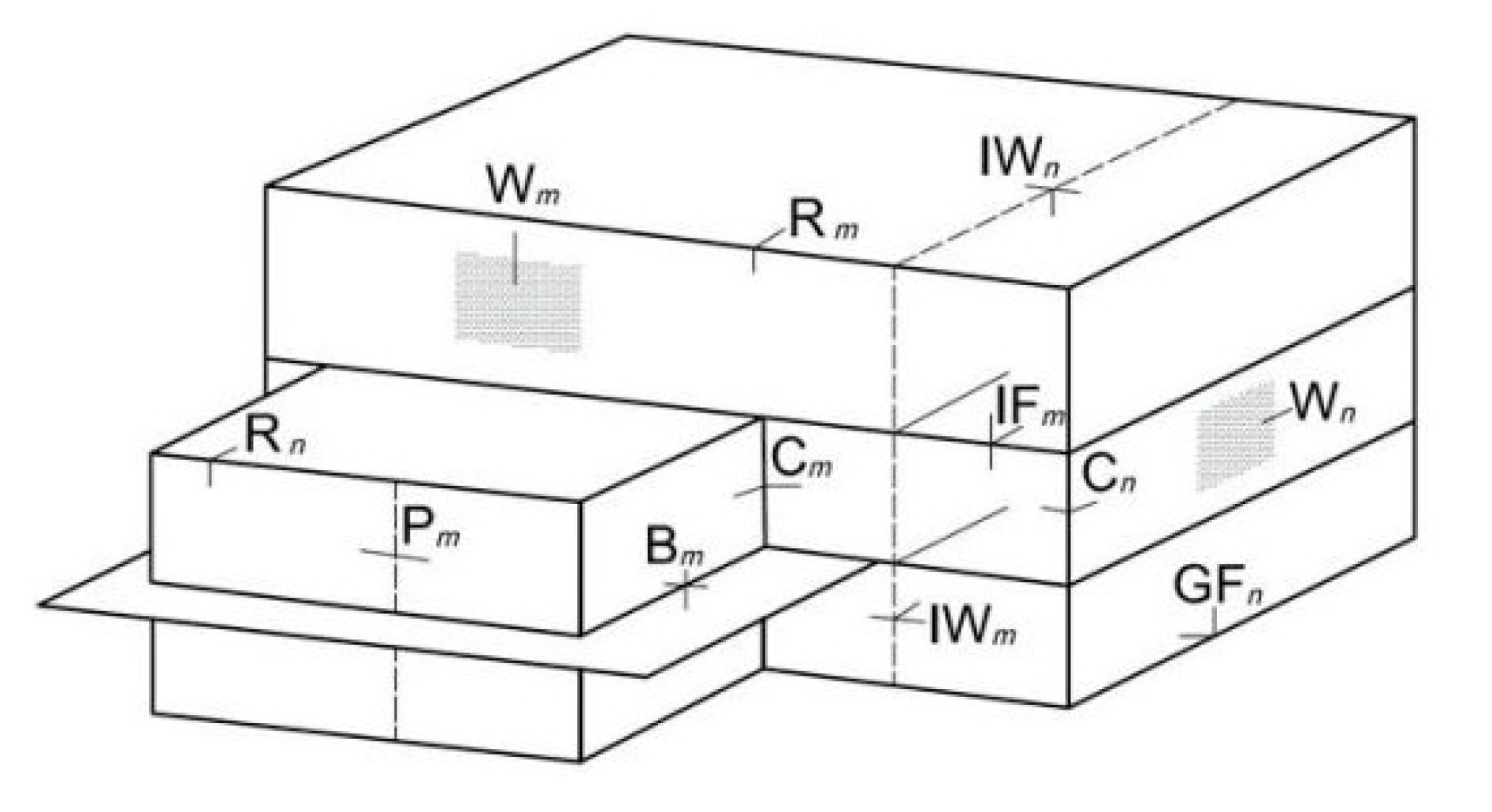
The standard UNI EN ISO 14683:2008 [36] indicates how to determine the linear transmittance of thermal bridging. Some reference values are given in Attachment A of the mentioned standard. Some common types of linear thermal bridging are displayed in Table 1 and Figure 2.
In such a way, the thermal transmittance can be easily calculated for the as-built and for the retrofitted state to obtain the variation needed for the iso-cost curves.

2.3. Structural Performance Indicators

With the purpose of determining the relative variation of the wall structural resistance, the variation of the maximum base shear Δ V and the variation of the ductility Δ μ are selected as reference indicators.
The relative variation of the structural parameter Δ V is assessed by the ratio of the performance variation between its value after ( V 1 ) and before the retrofitting ( V 0 ) to the initial value ( V 0 ) :
Δ V   =   V 1 V 0 V 0 .
Similarly, the variation of the ductility Δ μ reads:
Δ μ   =   μ 1 μ 0 μ 0 .
After each intervention, the structural performance of the façade improves, therefore, the parameters Δ V and Δ μ measure the structural improvement in terms of base shear and ductility, respectively.
These two parameters are calculated through non-linear static (pushover) analyses on the entire façade. The non-linear analysis allows then obtaining the capacity curves from which it is possible to identify the parameters’ values necessary for the study. The maximum base shear V represents the maximum value of the base shear shown in the analysis’ steps, instead, the ductility μ is calculated by the ratio between the maximum displacement and the displacement at the onset of yielding (identified on the equivalent bilinear curve by which the capacity curve is approximated).

3. Application of the Integrated Approach at Mesoscale Level

In this section, the integrated approach applies at the mesoscale level to a case study consisting of a façade of an existing stone masonry building.

3.1. Case of Study

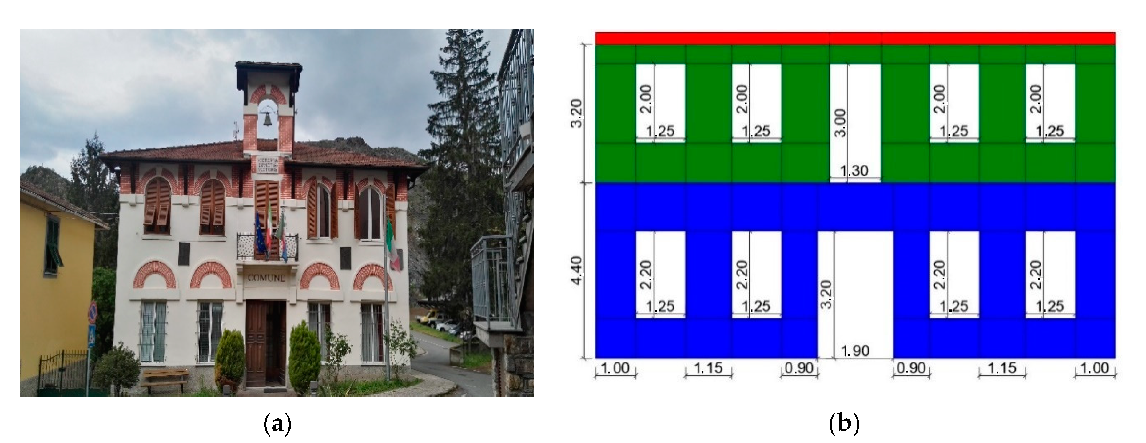
The building under examination is the seat of a Municipality located in Northern Italy (Figure 3). The two-storey building is made of stone masonry arranged in good texture, with a structural thickness of 60 cm at the ground floor and 52 cm on the first floor. The numerical analysis is performed for the case under study with 3D MACRO software [37], which models masonry buildings through a macro-element approach. This method can be very useful for existing buildings, especially historic buildings for which the macro-element approach reveals to be reliable if compared with common finite element models [38]. The assumptions of nonlinear material according to the mechanical parameters listed in Table 2—and estimated from [39]—are made.
The considered façade, displayed in Figure 3a, is quite regular with five openings (one door and four windows) for each storey. The macro-element model with geometrical dimensions is shown in Figure 3b.

3.2. Assumptions on the Integrated Interventions

As for masonry, the assumption is that the properties of blocks and mortar joints of each panel are homogenized.
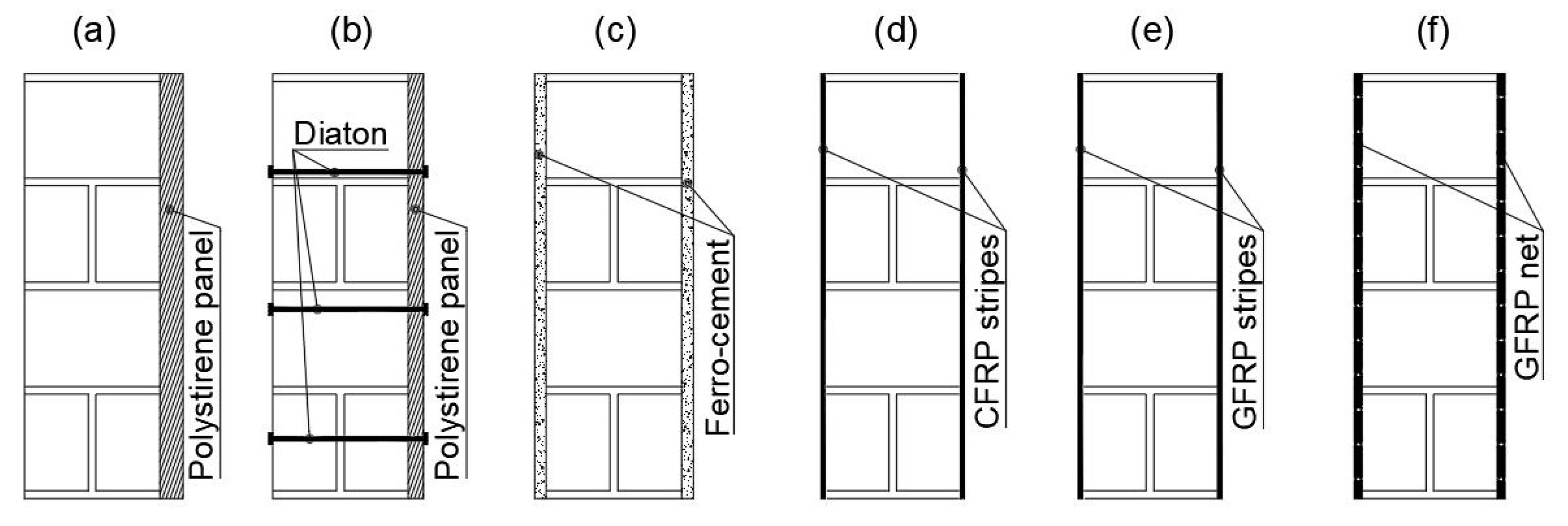
The considered types of interventions are similar to those assumed in [28] and are indicated in Figure 4.
Solution (a) consists in a polystyrene insulating panel with a thermal conductivity λ   =   0.04   W / mK . This is a typical intervention for which the structural strength is not increased, but the energy efficiency is. The same insulating panel is adopted in solution (b), with the addition of transverse connectors to get an additional improvement in the structural sense. Solution (c) consists in the classical ferro-cement made of two layers of concrete ( λ   =   1.60   W / mK ) on the two sides of the masonry wall, applied over an armature of metal mesh and closely spaced steel rods. This type of intervention allows improving the mechanical properties of masonry, but does not offer good thermal insulation. In solution (d) Carbon Fiber Reinforced Polymers (CFRP) strips are installed on both sides of the masonry panel. Their thickness is 0.133 mm and the thermal conductivity is λ   =   0.08   W / mK . The tensile mechanical strength of CFRP is f C F R P   =   4.83   GPa and the normal elastic modulus is E C F R P   =   252   GPa . Analogously, solution (e) consists in Glass Fiber Reinforced Polymers (GFRP) of thickness 0.48 mm and thermal conductivity of λ   =   0.04   W / mK . GFRP tensile strength is f G F R P   =   2.56   GPa and the elastic modulus E C F R P   =   80.7   GPa . The width of the strips and their disposition vary depending on the extension of the intervention. Only horizontal and vertical strips are considered. The two latter techniques have a significant improvement in mechanical behavior and a low thermal conductivity. Nevertheless, they imply a reduction of the wall ductility, which has to be considered as detrimental in the seismic zone. Solution (f) is an application of a GFRP net on both sides of the wall with a mesh of approximate dimensions 100 mm × 100 mm. It has a tensile strength equal to 3500 N and axial stiffness of 230 kN/m. This solution does not increase the thermal resistance due to the absence of an insulating layer, but permits to improve the structural response.

3.3. The Procedure of Estimation of the Varied Mechanical and Thermal Properties

The variation of mechanical properties in the presence of integrated interventions can be estimated, with the purpose of large scale analysis, through the indications reported in [39]. For existing masonry buildings, corrective coefficients are given to modify the strength and elastic modulus values. For instance, when transverse connections are considered, the structural improvement is evaluated by incrementing the masonry mechanical properties by 30%. Analogously, the increase of mechanical properties of the stone masonry when ferro-cement is added is 50%. As for the fiber-reinforced polymer-based interventions, an elasto-plastic constitutive law is considered, with an assumed strain limit. Beyond the strength value, the maximum delamination force is considered for the fiber composite system.
An FRP-based solution increases both flexural and shear strength: the increment of tensile strength is evaluated by considering the ultimate strength of the reinforcement ( f f R ) given by the minimum between the design strength of the fibers and the delamination strength. The increases of strength in vertical ( Δ σ t , v ) and horizontal ( Δ σ t , v ) direction respectively are [40]:
Δ σ t , v   =   A h · f f R p h · s ;   σ t , h   =   A v · f f R p v · s ,
where:
  • s is the wall thickness;
  • A h ,   A v are the reinforcement area placed in horizontal and vertical direction per unit of length;
  • p h ,   p v are the spacings between horizontal or vertical strips.
Analogously, it is possible to define the increment of shear strength:
Δ τ   =   V R b · s   =   0.6 · 1 3 ( A h p h + A v p v ) · f f R s 0.3 · f k τ 0 ,
where V R is the shear strength of reinforced masonry that is determined as the sum of the strength of the unreinforced wall ( V R m ) and the shear strength offered by the fibers   ( V R f ) , namely:
V R   =   V R m + V R f V R , m a x ,
in which:
  • V R f   =   0.6 · d · 1 2 ( A h p h + A v p v )   f f R   is the reinforcement strength, by considering the effective shear length of the panel d   =   2 / 3 · b [37,40]
  • V R , m a x   =   0.3 · f k · s · b .
The thermal transmittance U , and its variation Δ U needed for the iso-cost curves, is calculated for the façade with the indications reported in UNI EN ISO 6946:2008, as stated in Section 2.2 In particular, the façade under examination has eight windows and two doors with aluminum frame support with double glazed glass 4–9–4. The transmittance of the frame support is U f   = 3.0   W / m 2 K , and of the glass, U g   =   3.1   W / m 2 K . By crossing these values, the window has a value of thermal transmittance of U w   =   3.3   W / m 2 K . The wood door is assumed to have U d = 1.5   W / m 2 K (wood thermal conductivity of λ   =   0.22   W / mK ). As for the linear thermal transmittance, it has been assumed Ψ   =   0.60   W / m K . Finally, the thermal transmittance of the entire façade in the as-built configuration is U   =   2.937   W / m 2 K . In case of the retrofitting interventions described in Section 3.2., the values of the thermal transmittance are analogously calculated (Table 3 and Table 4). All the interventions cause a reduction of the thermal transmission; the best improvement is obtained with the polystyrene panel. The corresponding base shear capacity and ductility values are reported in Table 5, Table 6, Table 7 and Table 8.

3.4. Cost Analysis

3.4.1. Economic Cost Analysis

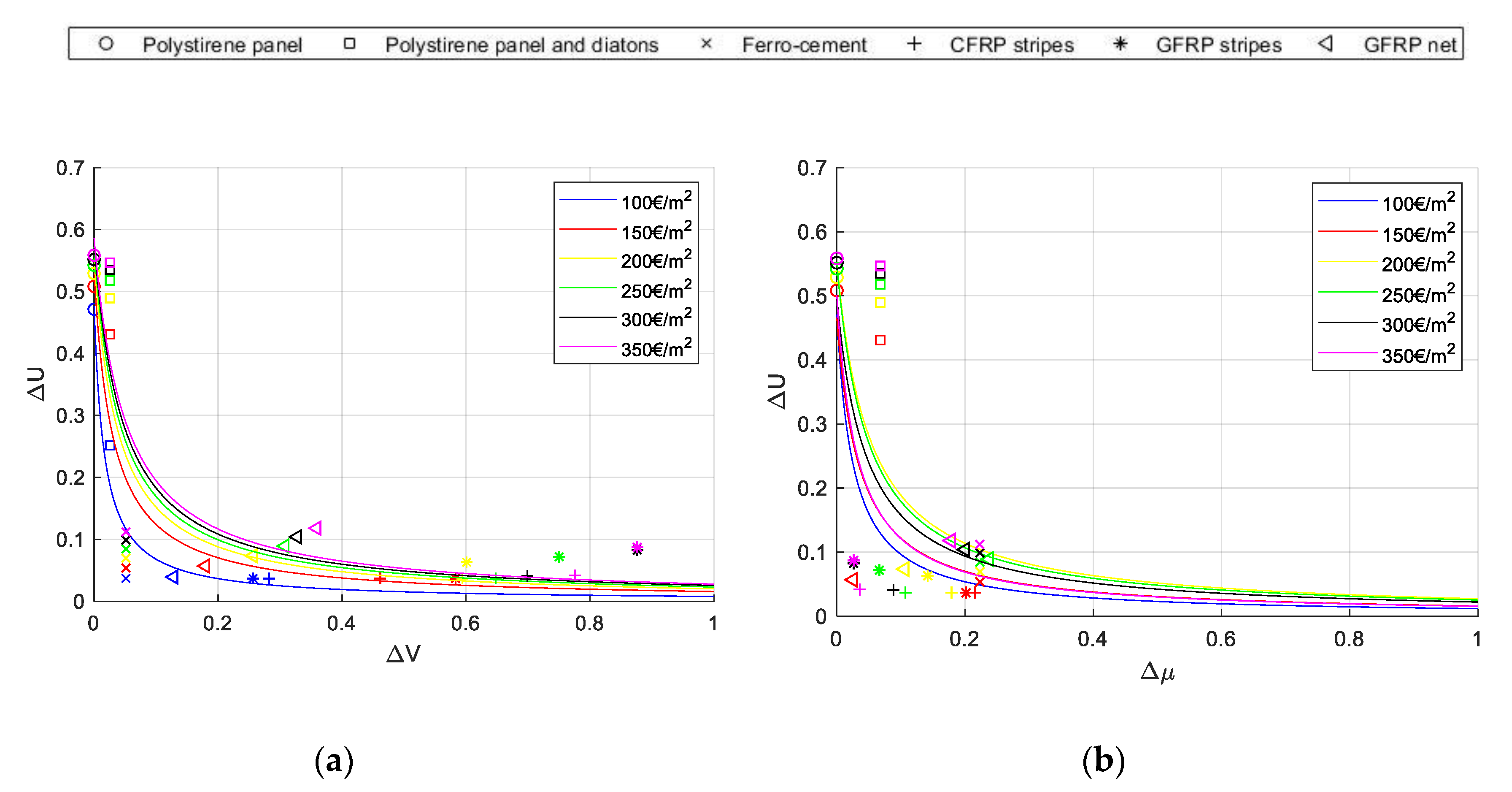
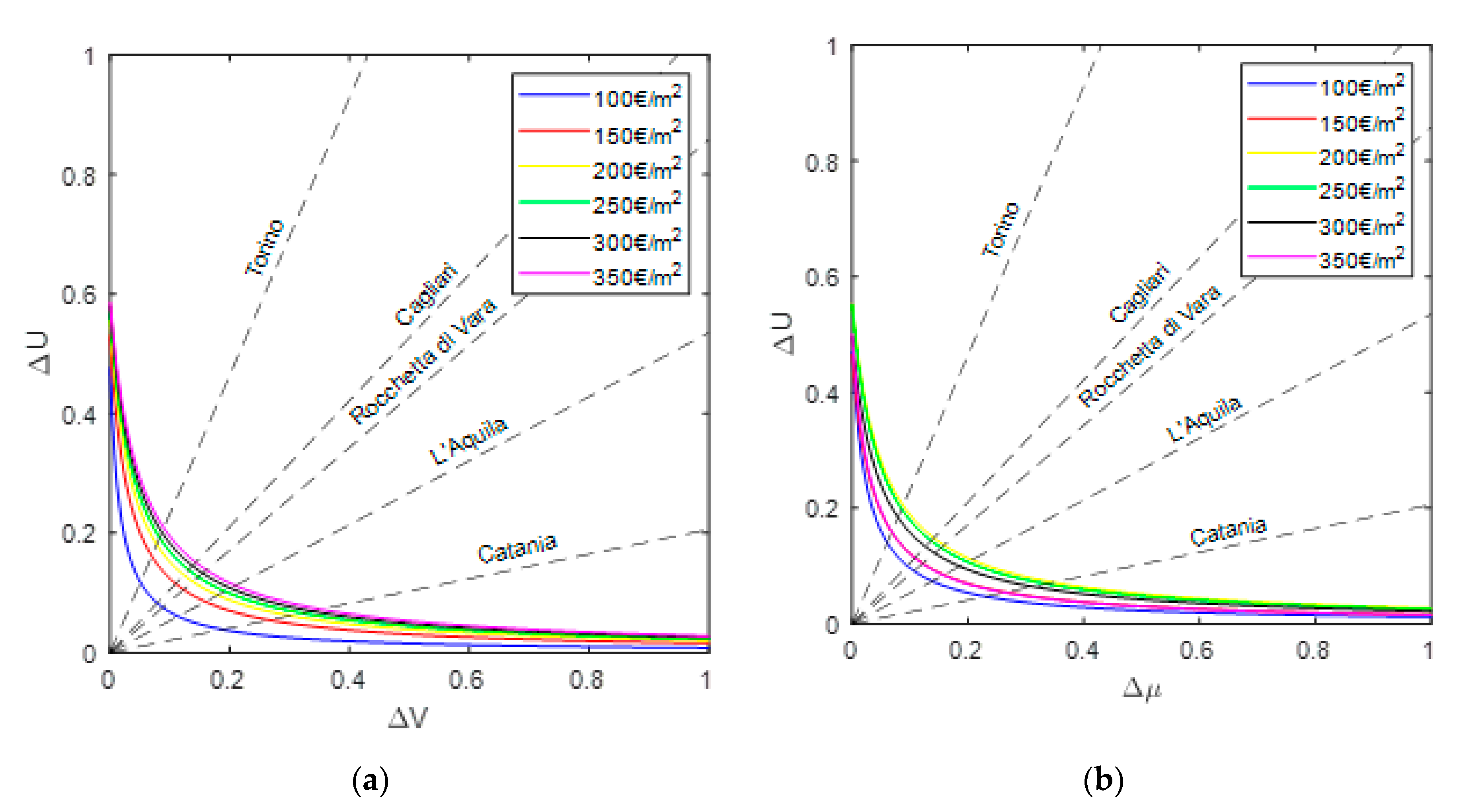
Analogously to the study performed in [28], an economical relationship has been found between Δ V (or Δ μ ), that is the seismic performance indicator, and Δ U , the energetic performance indicator. Six different solutions have been considered (Figure 2), with costs ranging from 100   / m 2 to   350   / m 2 . For the sake of comparison, the same unitary costs (supply and manpower) as those considered in [28] have been used for each individual intervention (Section 3.2.) as indicated in Table 9. For each intervention, the layer thickness has been tuned to meet a target cost between 100   / m 2 to   350   / m 2 . It is then possible to calculate by means of the expressions reported in Section 2.2 and Section 2.3. the capacity curves Δ U Δ V and Δ U Δ μ , each one representing the performance offered by each intervention among the six selected. Each curve is obtained by curve fitting of the points, each one representative of a single integrated intervention.
In particular, the points in the graph (displayed in Figure 5a) have been interpolated with a proper curve fitting through hyperbolic regression curves:
Δ U ( α 1 + Δ V )   =   α 0 .
The parameters α 0 and α 1 are obtained by means of a minimum square criterion and are listed in Table 10. Hyperbolic type curves provided the best estimation by using a reduced number of parameters to describe this relationship. It is worthy to notice that not always the fitting capacity curves are of hyperbolic shape. Indeed, for this set of retrofitting strategies, this is the case, but for other retrofitting techniques the response will generally be different. If, for example, integrated approaches resulting in similar variations of thermal transmittance but significantly increase structural strength, the fitting capacity curve would be flatter and tending to a horizontal line. The analogous approach has been adopted for the Δ U Δ μ regression curves (Figure 5b).
Figure 5 shows that the maximum structural improvement is attained with FRP stripes (solutions d and e) in terms of increase of shear base strength Δ V . Nevertheless, these interventions significantly reduce the increase in ductility. Table 11 reports the corresponding regression coefficients for the curves Δ U Δ μ .

3.4.2. Environmental Cost Analysis

The same analysis performed in economic terms is proposed here from an environmental point of view. The aim of this analysis is to limit the CO2eq emissions that are normally produced when retrofitting interventions are made. The CO2eq emission is one of the main indicators chosen to measure building sustainability.
As any other commercial product, each building product implies a certain level of emissions: extraction of raw materials, manufacturing process, transport of materials from the source to the destination, the emissions during the construction, use, maintenance works and demolition, in a perspective of life cycle assessment. Provided that the aim of the paper is the choice of the optimal consolidation technique, only the CO2eq emissions related to the phase of production of the materials for intervention are considered. Although this analysis can be extended to the entire life of the building, this paper neglects that aspect, which will be considered in future works. The assumed parameter of CO2eq emission varies from 5 kgCO2eq/m3 to 35 kgCO2eq/m3. The specific environmental costs for each material are reported in Table 12.
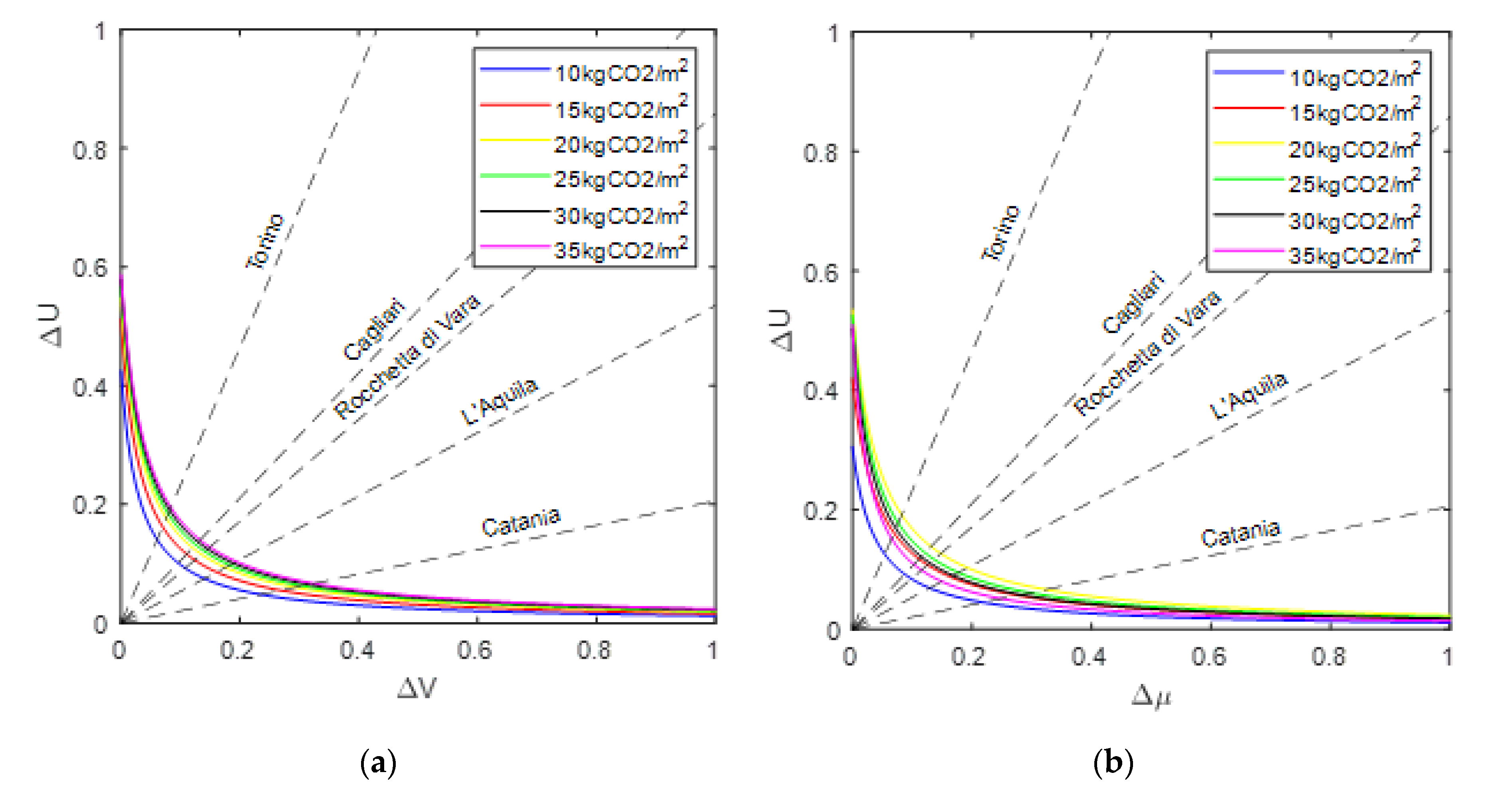
The regression parameters α0 and α1 are reported in Table 13 and in Table 14, whilst Figure 6 shows the environmental regression curves for Δ U Δ μ ( Δ U Δ V ).
It should be noticed that, for the same motivation mentioned above, solutions (a) and (b) are the best choices to obtain a strong improvement of the thermal performance of the wall, whereas solutions (d) and (e) guarantee an intermediate increment of the base shear, but, if the quantity of the FRP stripes increases, there is a reduction of ductility which is not optimal from a seismic point of view.

4. Definition of Demand Curves and Discussion of Results

Steps (5) and (6) of the procedure described in Section 2.1 lead to graphs reporting demand and capacity curves, which synthetically describe the structural, economic and environmental impact of the interventions adopted. Some sites are chosen to compare the demand of the site construction of the case study (Rocchetta di Vara, Italy) to that of other significant sites in Italy (Torino, L’Aquila, Catania, Cagliari, Italy). The demand lines are obtained, as already discussed, according to the equation:
Δ U   =   α c U c R Δ V ;   Δ U   =   α c U c R Δ μ
with symbols defined in Section 2.1. As visible in Figure 7 and Figure 8, the demand line of Rocchetta di Vara stands between those chosen as reference locations. The hyperbolic graphs in the same Figures represent the trend of capacity obtained by the retrofitting techniques, in terms of seismic and thermal improvements. The graphs in Figure 7 are plotted in terms of economic costs (investment in €), and in Figure 8, in terms of environmental costs (CO2). The optimal point for each location is given by the intersection of the lines with the hyperboles. The decision-makers can act through two aspects: which hyperbole should be considered (i.e., which level of economic or environmental cost) and which “tuning parameter” α has to be assumed (i.e., the slope of the line graphs) to give more importance to the thermal or to the seismic aspect, provided that the location influences the inclination of the line through the coefficients of Equation (1).
As for the demand curves, the tuning parameter α has been here set equal to 1. Table 15 lists the parameters needed for the definition of the demand curves.
These graphs are of immediate use: for a fixed maximum budget that a public administration or a private owner has, it is possible to estimate the level of performance that can be gained in terms of thermal and structural behavior. Therefore, for instance with a budget of 100 €/m2 one should expect in Rocchetta di Vara an increase of base shear strength by 7%, of ductility by 10% and of thermal transmittance by 8%, whereas with a budget of 300 €/m2 the expected increase of base shear and thermal transmittance are respectively by 14% and 17%. It should be noticed that the information gathered by this procedure is able to give an overall look at the improvement obtained by integrated approaches. An alternative way to proceed is to define the capacity curves by keeping constant the type of intervention and tuning its thickness, or coupling two interventions, one with more impact on the structural performance, and the other more effective from a thermal point of view. This procedure, which will be investigated in the future, will allow us to refine the decisional practice about the intervention to adopt.
It can be observed that there is not a monotonic trend of improvement of the performance indicators by increasing the environmental costs: indeed, for instance, the curve corresponding to 350 €/m2 stands between that obtained for 100 €/m2 and that for 300 €/m2 (Figure 8). This aspect is due to the fact that for the FRP interventions, beyond a threshold value, the increase of the cost (and therefore of the entity of the intervention) does not imply an increment of ductility, but instead a decrement of it. In other words, a greater thickness of FRP strips worsens the structural performance. This influence is stronger with respect to the other interventions and therefore the fitted curves do not follow a monotonic trend. A way to avoid this apparently counter-intuitive response is, as mentioned above, to plot the fitted curves for interventions with similar and monotonic effects.

5. Conclusions

This paper presented a mesoscale approach for masonry buildings to optimize retrofitting interventions capable of improving the structural and thermal performances of an existing building. These integrated interventions can be read in terms of seismic indicators, such as variation of base shear strength and variation of ductility, and in terms of a thermal indicator, such as variation of thermal transmittance. The performance indicators are calculated for external façades of masonry buildings (mesoscale level, different from the macroscale involving the whole building), considering their openings (windows, doors). Economic and environmental iso-cost curves have been obtained from cost analysis to measure the level of financial commitment and sustainable impact on the environment associated with each type of intervention. The graphs reporting demand and capacity curves were revealed to be effective and of immediately readable since, for a fixed maximum budget that a public administration or a private owner has at their disposal, it is possible to find the level of improvement that can be gained in terms of thermal and structural behavior. An alternative way to proceed is to define the capacity curves by keeping constant the type of intervention and tuning its thickness, or combining two interventions. This procedure, which will be investigated in the future, will allow us to refine the decisional practice about the intervention to adopt. Finally, another future development will extend the procedure to a macroscale level, by considering seismic and thermal performance indicators able to properly take into account the performance of the whole building.

Author Contributions

L.G. and M.S. conceived the methodology and its application to real cases; L.G. analyzed the case study and wrote the paper. S.P. made calculations and produced tables and figures. All authors have read and agreed to the published version of the manuscript.

Funding

This research was funded by RELUIS, Italian Department of Civil Protection, WP5.2.

Conflicts of Interest

The authors declare no conflict of interest.

References

  1. De Falco, A.; Giresini, L.; Sassu, M. Temporary Preventive Seismic Reinforcements on Historic Churches: Numerical Modeling of San Frediano in Pisa. Appl. Mech. Mater. 2013, 351, 1393–1396. [Google Scholar] [CrossRef]
  2. Casapulla, C.; Maione, A.; Argiento, L.U. Seismic analysis of an existing masonry building according to the multi-level approach of the italian guidelines on cultural heritage. Ing. Sismica 2017, 34, 40–59. [Google Scholar]
  3. Casapulla, C.; Argiento, L.U. In-plane frictional resistances in dry block masonry walls and rocking-sliding failure modes revisited and experimentally validated. Compos. Part B Eng. 2018, 132, 197–213. [Google Scholar] [CrossRef]
  4. Alecci, V.; De Stefano, M.; Galassi, S.; Lapi, M.; Orlando, M. Evaluation of the American Approach for Detecting Plan Irregularity. Adv. Civ. Eng. 2019, 2019, 1–10. [Google Scholar] [CrossRef] [Green Version]
  5. Alecci, V.; De Stefano, M. Building irregularity issues and architectural design in seismic areas. Frat. Integrità Strutt. 2018, 13, 161–168. [Google Scholar] [CrossRef]
  6. Gattesco, N.; Boem, I.; Dudine, A. Diagonal compression tests on masonry walls strengthened with a GFRP mesh reinforced mortar coating. Bull. Earthq. Eng. 2014, 13, 1703–1726. [Google Scholar] [CrossRef]
  7. Giresini, L.; Sassu, M.; Butenweg, C.; Alecci, V.; De Stefano, M. Vault macro-element with equivalent trusses in global seismic analyses. Earthq. Struct. 2017, 12, 409–423. [Google Scholar] [CrossRef]
  8. Giresini, L.; Solarino, F.; Paganelli, O.; Oliveira, D.V.; Froli, M. One-sided rocking analysis of corner mechanisms in masonry structures: Influence of geometry, energy dissipation, boundary conditions. Soil Dyn. Earthq. Eng. 2019, 123, 357–370. [Google Scholar] [CrossRef]
  9. Giresini, L.; Casapulla, C.; Denysiuk, R.; Matos, J.C.; Sassu, M. Fragility curves for free and restrained rocking masonry façades in one-sided motion. Eng. Struct. 2018, 164, 195–213. [Google Scholar] [CrossRef]
  10. Giresini, L. Design strategy for the rocking stability of horizontally restrained masonry walls. In Proceedings of the COMPDYN 2017, 6th ECCOMAS Thematic Conference on Computational Methods in Structural Dynamics and Earthquake Engineering, Rhodes Island, Greece, 15–17 June 2017. [Google Scholar]
  11. Alecci, V.; Stipo, G.; La Brusco, A.; De Stefano, M.; Rovero, L. Estimating elastic modulus of tuff and brick masonry: A comparison between on-site and laboratory tests. Constr. Build. Mater. 2019, 204, 828–838. [Google Scholar] [CrossRef]
  12. Giresini, L.; Sassu, M.; Sorrentino, L. In situ free-vibration tests on unrestrained and restrained rocking masonry walls. Earthq. Eng. Struct. Dyn. 2018, 47, 3006–3025. [Google Scholar] [CrossRef]
  13. Giresini, L.; Puppio, M.L.; Taddei, F. Experimental pull-out tests and design indications for strength anchors installed in masonry walls. Mater. Struct. 2020, 53, 1–16. [Google Scholar] [CrossRef]
  14. Goncalves, M. Insulating Solid Masonry Walls. Available online: www.cebq.org (accessed on 26 May 2020).
  15. Schiavi, A.; Cellai, G.; Secchi, S.; Brocchi, F.; Grazzini, A.; Prato, A.; Mazzoleni, F. Stone masonry buildings: Analysis of structural acoustic and energy performance within the seismic safety criteria. Constr. Build. Mater. 2019, 220, 29–42. [Google Scholar] [CrossRef]
  16. Sassu, M.; Giresini, L.; Bonannini, E.; Puppio, M.L. On the Use of Vibro-Compressed Units with Bio-Natural Aggregate. Buildings 2016, 6, 40. [Google Scholar] [CrossRef] [Green Version]
  17. Mistretta, F.; Piras, M.V.; Fadda, M.L. A Reliable Visual Inspection Method for the Assessment of R.C. Structures Through Fuzzy Logic Analysis. In Life-Cycle of Structural Systems: Design, Assessment, Maintenance and Management—Proceedings of the 4th International Symposium on Life-Cycle Civil Engineering, Tokyo, Japan, 14–16 November 2014; Taylor & Francis Group: London, UK, 2015; pp. 1154–1160. [Google Scholar]
  18. Andreini, M.; Sassu, M. Mechanical behaviour of full unit masonry panels under fire action. Fire Saf. J. 2011, 46, 440–450. [Google Scholar] [CrossRef] [Green Version]
  19. Meloni, P.; Mistretta, F.; Stochino, F.; Carcangiu, G. Thermal Path Reconstruction for Reinforced Concrete Under Fire. Fire Technol. 2019, 55, 1451–1475. [Google Scholar] [CrossRef]
  20. Kumar, R.; Gardoni, P. Renewal theory-based life-cycle analysis of deteriorating engineering systems. Struct. Saf. 2014, 50, 94–102. [Google Scholar] [CrossRef]
  21. Biswas, W. Carbon footprint and embodied energy consumption assessment of building construction works in Western Australia. Int. J. Sustain. Built Environ. 2014, 3, 179–186. [Google Scholar] [CrossRef] [Green Version]
  22. Sharma, N.; Tabandeh, A.; Gardoni, P. Resilience analysis: A mathematical formulation to model resilience of engineering systems. Sustain. Resilient Infrastruct. 2017, 3, 49–67. [Google Scholar] [CrossRef] [Green Version]
  23. Galadanci, A.S.; Ianakiev, A.; Kromanis, R.; Robinson, J. Energy investigation framework: Understanding buildings from an energy perspective view. J. Build. Eng. 2020, 28, 101046. [Google Scholar] [CrossRef]
  24. Ma, Z.; Cooper, P.; Daly, D.; Ledo, L. Existing building retrofits: Methodology and state-of-the-art. Energy Build. 2012, 55, 889–902. [Google Scholar] [CrossRef]
  25. Calvi, G.; Sousa, L.; Ruggeri, C. Energy Efficiency and Seismic Resilience: A Common Approach. In Multi-Hazard Approaches to Civil Infrastructure Engineering; Gardoni, P., LaFave, J.M., Eds.; Springer: Berlin/Heidelberg, Germany, 2016; pp. 165–208. [Google Scholar]
  26. Global Alliance for Buildings and Construction. Global Status Report. 2018. Available online: https://www.unenvironment.org/resources/report/global-status-report-2018 (accessed on 23 July 2020).
  27. Sassu, M.; Stochino, F.; Mistretta, F. Assessment Method for Combined Structural and Energy Retrofitting in Masonry Buildings. Buildings 2017, 7, 71. [Google Scholar] [CrossRef] [Green Version]
  28. Mistretta, F.; Stochino, F.; Sassu, M. Structural and thermal retrofitting of masonry walls: An integrated cost-analysis approach for the Italian context. Build. Environ. 2019, 155, 127–136. [Google Scholar] [CrossRef]
  29. Hasik, V.; Escott, E.; Bates, R.; Carlisle, S.; Faircloth, B.; Bilec, M.M. Comparative whole-building life cycle assessment of renovation and new construction. Build. Environ. 2019, 161, 106218. [Google Scholar] [CrossRef]
  30. Italian Institute of Geophysics and Volcanology: Map of Seismic Hazard. Available online: https.www.ingv.it (accessed on 26 May 2020).
  31. EN ISO 15927-6 Hygrothermal Performance of Buildings—Calculation and Presentation of Climatic Data—Part 6: Accumulated Temperature Differences (Degree-Days); International Organization for Standardization: Geneva, Switzerland, 2007; pp. 1–13.
  32. UNI EN ISO 6946:2008. Componenti ed Elementi per Edilizia—Resistenza Termica e Trasmittanza Termica—Metodo di Calcolo; International Organization for Standardization: Geneva, Switzerland, 2008; pp. 1–28. [Google Scholar]
  33. UNI 10351:1994. Building Materials. Thermal Conductivities and Vapour Permeabilities; International Organization for Standardization: Geneva, Switzerland, 1994; pp. 1–21. [Google Scholar]
  34. EN ISO 10077-1:2006. Thermal Performance of Windows, Doors and Shutters—Calculation of Thermal Transmittance; International Organization for Standardization: Geneva, Switzerland, 2006; pp. 1–35. [Google Scholar]
  35. UNI EN ISO 10211:2008. Thermal Bridge in Buildings—Thermal Flow and Surface Temperatures—Calculation Methods; International Organization for Standardization: Geneva, Switzerland, 2008; pp. 1–55. [Google Scholar]
  36. UNI EN ISO 14683:2008. Thermal Bridges in Building Construction—Linear Thermal Transmittance—Simplified Methods and Default Values; International Organization for Standardization: Geneva, Switzerland, 2008; pp. 1–27. [Google Scholar]
  37. Gruppo Sismica, s.r.l. 3D MACRO—Computer Program for Modelling the Seismic Behavior of Masonry Buildings. Modellazione di Pannelli Murari Rinforzati nel Piano con Reti Fibrenet in GFRP e Malta di Calce; Gruppo Sismica s.r.l.: Catania, Italy, 2020. [Google Scholar]
  38. Pantò, B.; Giresini, L.; Sassu, M.; Calio, I. Non-linear modeling of masonry churches through a discrete macro-element approach. Earthq. Struct. 2017, 12, 223–236. [Google Scholar] [CrossRef]
  39. Ministero delle Infrastrutture e dei Trasporti. Circolare Applicativa 21 Gennaio 2019, n. 7; Ministero delle Infrastrutture e dei Trasporti: Codroipo, Italy, 2019.
  40. National Research Council. CNR-DT 200/2004: Guide for the Design and Construction of Externally Bonded FRP Systems for Strengthening Existing Structures; National Research Council: Rome, Italy, 2004; pp. 80–110. [Google Scholar]
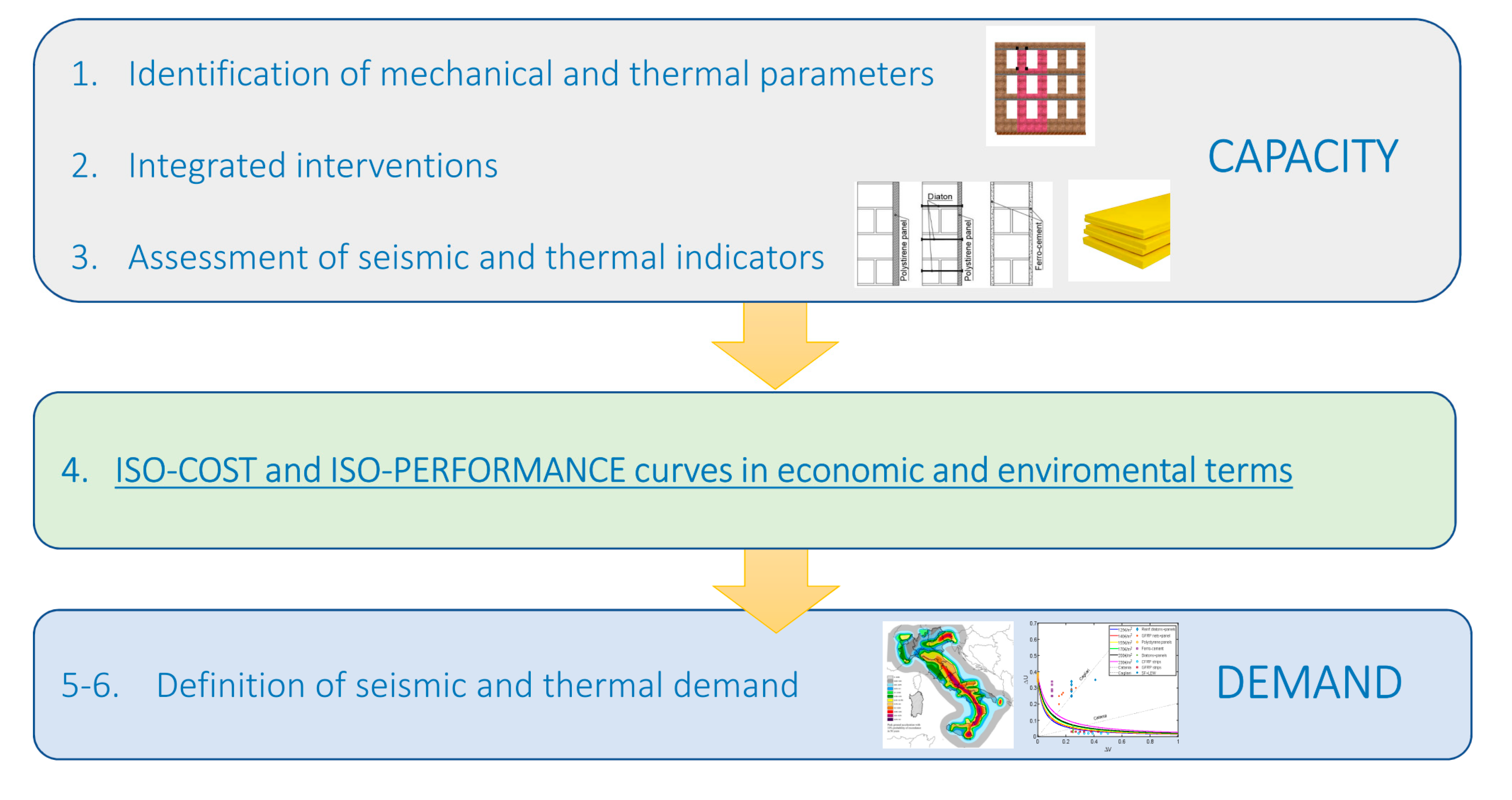
Figure 1. Flowchart of the proposed procedure.
Buildings 10 00143 g001
Figure 2. Disposition of the most common linear thermal bridging (Figure 1, paragraph 5.4 UNI EN ISO 14683).
Buildings 10 00143 g002
Figure 3. Façade selected as a case study for the integrated meso-scale approach (a); macro-element model of the façade (units in m) (b).
Buildings 10 00143 g003
Figure 4. Types of integrated interventions assumed in the case study: polystyrene panel (a), polystyrene panel and diatons (b); ferro-cement (c); CFRP (d) and GFRP (e) stripes; GFRP net (f).
Buildings 10 00143 g004
Figure 5. Iso-cost Δ U Δ V (a) and Δ U Δ μ (b) regression curves.
Buildings 10 00143 g005
Figure 6. Environmental iso-cost Δ U Δ V (a) and Δ U Δ μ (b) regression curves.
Buildings 10 00143 g006
Figure 7. Economic performance curves for planes Δ U Δ V (a) and Δ U Δ μ (b).
Buildings 10 00143 g007
Figure 8. Environmental performance curves for planes Δ U Δ V (a) and Δ U Δ μ (b).
Buildings 10 00143 g008
Table 1. Type of linear thermal bridging (Figure 1, paragraph 5.4 UNI EN ISO 14,683 [36]).
RConnections Between External ElementsCorners Between Vertical Walls and Roof
BCorners between vertical walls and projecting elements
CCorners between vertical walls
GFCorner between vertical walls and floors
IFCorners between external vertical walls and intermediate floors
IWCorners between inner vertical walls and external elements
PPresence of external columns
WPresence of doors and windows
Table 2. Masonry parameters: fm,k average compression strength, τ0: shear strength in absence of normal stress, E: elastic modulus, G: tangential elastic modulus, w: specific weight, λ: thermal conductivity.
fm,kτ0EGwλ
[N/mm2][N/mm2][N/mm2][N/mm2][kN/m3][W/mK]
3.200.0651740.00580.0021.002.30
Table 3. Thermal transmittance U of the entire façade with the different integrated interventions—economic analysis.
Type of InterventionInvestment
100 €/m2150 €/m2200 €/m2250 €/m2300 €/m2350 €/m2
Polystyrene panel1.7531.6601.6081.5741.5511.534
Polystyrene panel + diatons2.3051.8541.7081.6361.5931.564
Ferro-cement2.8452.8022.7622.7252.6892.656
CFRP strips2.8452.8452.8452.8452.8352.832
GFRP strips2.8452.8452.7792.7572.7302.718
GFRP net2.8392.7942.7532.7132.6762.641
Table 4. Thermal transmittance U of the entire façade with the different integrated interventions—environmental analysis.
Type of InterventionEmissions
10 kgCO2eq/m215 kgCO2eq/m220 kgCO2eq/m225 kgCO2eq/m230 kgCO2eq/m235 kgCO2eq/m2
Polystyrene panel1.9331.7291.6421.5931.5621.540
Polystyrene panel + diatons1.9501.7351.6451.5951.5631.541
Ferro-cement2.9152.8932.8722.8512.8312.812
CFRP strips2.8452.8452.8452.8452.8342.832
GFRP strips2.8452.8452.7662.7412.7302.718
GFRP net2.8482.8082.7692.7332.6992.666
Table 5. Base shear capacity V [kN] of the entire façade with the different integrated interventions—economic analysis.
Type of InterventionInvestment
100 €/m2150 €/m2200 €/m2250 €/m2300 €/m2350 €/m2
Polystyrene panel446.803446.803446.803446.803446.803446.803
Polystyrene panel + diatons458.259458.259458.259458.259458.259458.259
Ferro-cement469.716469.716469.716469.716469.716469.716
CFRP strips572.824653.019712.169736.157759.093793.436
GFRP strips561.367707.326715.263781.991838.286838.286
GFRP net504.085562.998561.367584.280595.737607.193
Table 6. Base shear capacity V [kN] of the entire façade with the different integrated interventions—environmental analysis.
Type of InterventionEmissions
10 kgCO2/m215 kgCO2/m220 kgCO2/m225 kgCO2/m230 kgCO2/m235 kgCO2/m2
Polystyrene panel446.803446.803446.803446.803446.803446.803
Polystyrene panel + diatons458.259458.259458.259458.259458.259458.259
Ferro-cement469.716469.716469.716469.716469.716469.716
CFRP strips607.193690.176715.270736.182770.554793.436
GFRP strips687.389726.755759.086816.354838.286838.286
GFRP net504.085515.541561.367572.000595.737607.193
Table 7. Ductility capacity µ of the entire façade with the different integrated interventions—economic analysis.
Type of InterventionInvestment
100 €/m2150 €/m2200 €/m2250 €/m2300 €/m2350 €/m2
Polystyrene panel2.6332.6332.6332.6332.6332.633
Polystyrene panel + diatons2.8112.8112.8112.8112.8112.811
Ferro-cement3.2203.2203.2203.2203.2203.220
CFRP strips3.3383.2013.1042.9152.8662.727
GFRP strips3.2353.1633.0062.8082.5632.563
GFRP net2.4772.5662.9113.2583.2603.302
Table 8. Ductility capacity µ of the entire façade with the different integrated interventions—environmental analysis.
Type of InterventionEmissions
10 kgCO2/m215 kgCO2/m220 kgCO2/m225 kgCO2/m230 kgCO2/m235 kgCO2/m2
Polystyrene panel2.6332.6332.6332.6332.6332.633
Polystyrene panel + diatons2.8112.8112.8112.8112.8112.811
Ferro-cement3.2203.2203.2203.2203.2203.220
CFRP strips2.9143.2533.0022.9472.8022.727
GFRP strips2.8122.9692.8752.7382.5632.563
GFRP net2.6032.6902.9112.9233.2603.285
Table 9. Economic specific costs of the materials in the design integrated techniques.
MaterialCost
Polystyrene panel1517 €/m3
Diatons80 €/m2
Ferro-cement2080 €/m3
CFRP stripes2160 €/m3
GFRP stripes1723 €/m3
GFRP nets4667 €/m3
Table 10. Economic cost regression coefficients for Δ U Δ V regression curves.
Economic Investmentα0α1
100 €/m20.00790.0166
150 €/m20.01620.0305
200 €/m20.02090.0376
250 €/m20.02400.0421
300 €/m20.02670.0460
350 €/m20.02910.0497
Table 11. Economic cost regression coefficients for Δ U Δ μ regression curves.
Economic Investmentα0α1
100 €/m20.01210.0258
150 €/m20.01650.0353
200 €/m20.02870.0519
250 €/m20.02650.0482
300 €/m20.02310.0465
350 €/m20.01600.0319
Table 12. Environmental specific costs of the materials in the design integrated techniques.
MaterialEmissions of CO2eq
Polystyrene panel138 kgCO2eq/m3
Diatons0.25 kgCO2eq/m2
Ferro-cement450 kgCO2eq/m3
CFRP stripes87,140 kgCO2eq/m3
GFRP stripes15,062 kgCO2eq/m3
GFRP nets520 kgCO2eq/m3
Table 13. Environmental cost regression coefficients for Δ U Δ V regression curves.
Environmental Impactα0α1
5 kgCO2eq/m20.01280.0301
10 kgCO2eq/m20.01660.0325
20 kgC kgCO2eq/m20.01990.0364
30 kgCO2eq/m20.02160.0381
40 kgCO2eq/m20.02320.0401
50 kgCO2eq/m20.02450.0417
Table 14. Environmental cost regression coefficients for Δ U Δ μ regression curves.
Environmental Impactα0α1
5 kgCO2eq/m20.01550.0377
10 kgCO2eq/m20.01820.0434
20 kgCO2eq/m20.02460.0460
30 kgCO2eq/m20.02060.0392
40 kgCO2eq/m20.01850.0367
50 kgCO2eq/m20.01420.0279
Table 15. Site parameters for the considered cases.
SitePGAicRDDicU
Rocchetta di Vara0.1200.43619340.374
Torino0.0600.21826170.507
L’Aquila0.2500.90925140.487
Catania0.2150.7828330.161
Cagliari0.0500.1829900.192