Article

Evaluating the Vertical Extension Module of a Building with Installed Rotary Dampers at Joints

Department of architecture, School of Engineering, Dankook University, 152 Jukjeon-ro, Yongin-si 16890, Gyeonggi-do, Korea
*
Author to whom correspondence should be addressed.
Buildings 2021, 11(11), 536; https://doi.org/10.3390/buildings11110536
Submission received: 6 October 2021 / Revised: 8 November 2021 / Accepted: 11 November 2021 / Published: 13 November 2021
(This article belongs to the Section Building Structures)

Abstract

:
In this study, the shape of a vertical expansion module with a rotary-type damping device is proposed. The external energy dissipation capacity is confirmed through experiments and the performance of the module is simulated. It can be easily applied to high-rise structures, as the module is directly supported by the bearing walls without the need for a separate base system. Additionally, as the damper can be replaced, it is possible to enhance seismic performance even after construction. The simulation results show that the rotary-type damper is more effective in reducing the displacement, shear force, and moment than free and fixed joints. In the pushover analysis of a system modeled using the moment hinge of the rotary damper of the joint, the best response reduction effect is obtained when the yield moment of the hinge is defined as 1% of the frame plastic moment. As a result of the analysis of the multi-degree-of-freedom system considering a harmonic load, we determined that it is efficient for the hinge to yield after the displacement, and the acceleration response of the resonant structure reaches steady state during the installation. In the multi-degree-of-freedom system with slab joints added to the analytical model, the displacement response decreased gradually as the natural period of the structure decreased and the joint increased. This provides evidence that the damper does not affect the overall behavior of the structure. The most important design factor of the rotary-type friction damper, shown through the experiment, is the relationship between the frictional surface and the tightening force of the bolt.

1. Introduction

Reinforced concrete wall-structured apartments are a unique type of residential structure in Korea; however, wall-structured apartments without longitudinal walls in the long-side direction are vulnerable to earthquakes [1]. Before 1988, an earthquake-resistant design was not enacted, and so there currently exist many buildings like that shown in Figure 1 [2]. This structure type can be applied using a tunnel-type mold, and there are cost reduction advantages related to the installation and disassembly of the formwork. In this system, the wall between the residential spaces with the major axis in the short side direction and the slab in the short side direction cannot restrict warping, such that this wall behaves independently [3].
In this case, as the stiffness and flexural strength of the wall in the long-side direction are very small, they can be neglected [4]. These wall structures are vulnerable to dynamic loads, such as wind and seismic loads, which are difficult to predict. Therefore, it is necessary to study methods to ensure the stability and usability of structures of this type. Wall-structured apartments are generally constructed of reinforced concrete. Methods for reinforcing the seismic performance of these structures include increasing the strength and stiffness by installing shear walls, braced frames, and buttresses; increasing the deformation capacity by restraining it with a fiber sheet; and reducing the size of the demand curve by installing an energy-dissipating attenuator, such as an isolator or a friction damper [5,6,7].
First, the method of adding reinforced concrete shear walls is the most efficient and traditional seismic reinforcement method to simultaneously increase the strength and stiffness, considering the associated costs [8]; however, this method requires a large number of shear walls and increases the total mass. Therefore, the overturning moment transmitted to the foundation is increased. As the moment increases, the size of the foundations must be changed to adhere to the earthquake load, which affects the overall construction cost [9]. Second, the method of adding a braced frame increases the strength and stiffness of the structure, similar to the shear wall reinforcement method, but the change in mass is smaller [10]. This method requires a sufficient number of anchors, as it uses anchor joints to integrate the existing structures with steel reinforcements [11]. In addition, this construction method is shorter than the wet construction method, by using a dry construction method. However, in many cases, structures existing in the direction of the long side cannot be used, such that the required number of additional steel frames to stiffen the reinforcing members is increased, which increases the construction cost [12]. Third, adding a shear wall or braced frame buttress to the exterior of the building requires an additional foundation system, but has the advantage of seismic reinforcement without touching the internal structure. Fourth, the method of increasing the deformation capacity is advantageous when it is possible to secure the deformation capability through the reinforcement of a few members but is not applicable to a structure having a large number of members to be reinforced, such as a wall structure [13]. Finally, the method using an isolation device is effective for structures with an independent foundation, while the method using an energy-dissipating device has the disadvantage that an additional brace system is required. Additionally, when installed indoors, the user prefers not to interfere with the interior design [3,6,14]. Other methods have been proposed by various researchers. In the case of remodeling for enlargement along with flat expansion in the Republic of Korea, it is possible to expand one floor when the first floor is changed to a parking lot or utilized as a common area, according to the newly revised housing law [15]. Most enlargement methods involve installing an upper layer having the same plane as the original structure, which increases the total load and burdens the lower column [16]. Therefore, Hong-Nan Li has recognized the necessity of reinforcing the seismic performance of the existing structure by using a vertical expansion structure, and proposed the relevant method [17,18]. In this method, as shown in Figure 2, a new column is installed, such that both new and old structures are supported as a separate structure by supporting the vertical extension structure. A friction layer is provided on the upper and lower surfaces of the two structures.
Then, an energy dissipative damping device is installed horizontally on the slab of the separation column and the old structure is installed for vertical expansion. In this case, energy dissipation occurs in the friction layer and the damping device, due to the displacement difference generated at the interface caused by the individual behavior of the two structures, and the seismic response of the new and old structures is reduced through energy dissipation. However, the method of Hong-Nan Li requires a separate column to support the new structure, such that it is difficult to apply to an existing high-rise structure. In addition, if the existing structure and the newly installed structure have the same period, the effect of reinforcing the seismic performance is almost eliminated. Therefore, it is difficult to control the magnitude of the force to reduce the displacement of the structure after construction. Another method, the steel moment frame system, is an excellent lateral resistance system with high ductility and energy dissipation ability, which exploits the inelastic behavior of a beam and panel zone [19]. However, earthquake damage occurred in more than 150 steel moment frames during the Northridge earthquake in the USA (1995), where most of the damage was brittle fracture due to abrupt deformation of the beam-column connection [20]. Therefore, many experiments and analytical studies have been carried out to solve the problem of the joint failure of steel moment frame systems, and a new joint design has been developed [11]. Commercial dampers are installed inside the building’s bracing, partition wall, or frame, in order to focus the dynamic loads acting on the structure. These damping devices often consume space—for example, occupying the space around the column and beam—or change the appearance of the structure [21,22]. Therefore, it is necessary to develop a joint-type damping device that can be installed at beam and column joints, where the energy is most concentrated when the earthquake load acts on the structure, and such that the internal space is not reduced. In addition, as damping devices are generally designed with consideration of the natural period and the physical characteristics of the structure to be installed and the expected dynamic load characteristics, it is difficult to control the damping force after installation. Therefore, it is necessary to develop a new lateral force resisting system with controlled performance through the energy dissipation of the damping device friction surface and with an easily replaceable attenuator.
In order to solve the above problems, we propose a modular design and a method for controlling vibration by reducing the external energy through the use of a rotary damper at the lower end beam. This method can be applied to high-rise structures easily, as it does not require a separate foundation system and supports the vertical expansion module directly by using the bearing wall. It is also possible to replace the rotary type damper. The required seismic performance can be effectively provided, regardless of the period of the structure, due to the characteristics of the damping device. We investigate the displacement and acceleration control performance, according to the magnitude of the frictional force and the period of new and old structures, using the method by Hong-Nan Li. Then, the kinetic equations of the cantilever structure with the rotary-type damping device are derived. We also simulate the shape of a vertical expansion module that can be installed in an actual apartment structure. Finally, the validity of the proposed method is verified by one- and multi-degree-of-freedom numerical analyses for structures under harmonic and seismic loads.

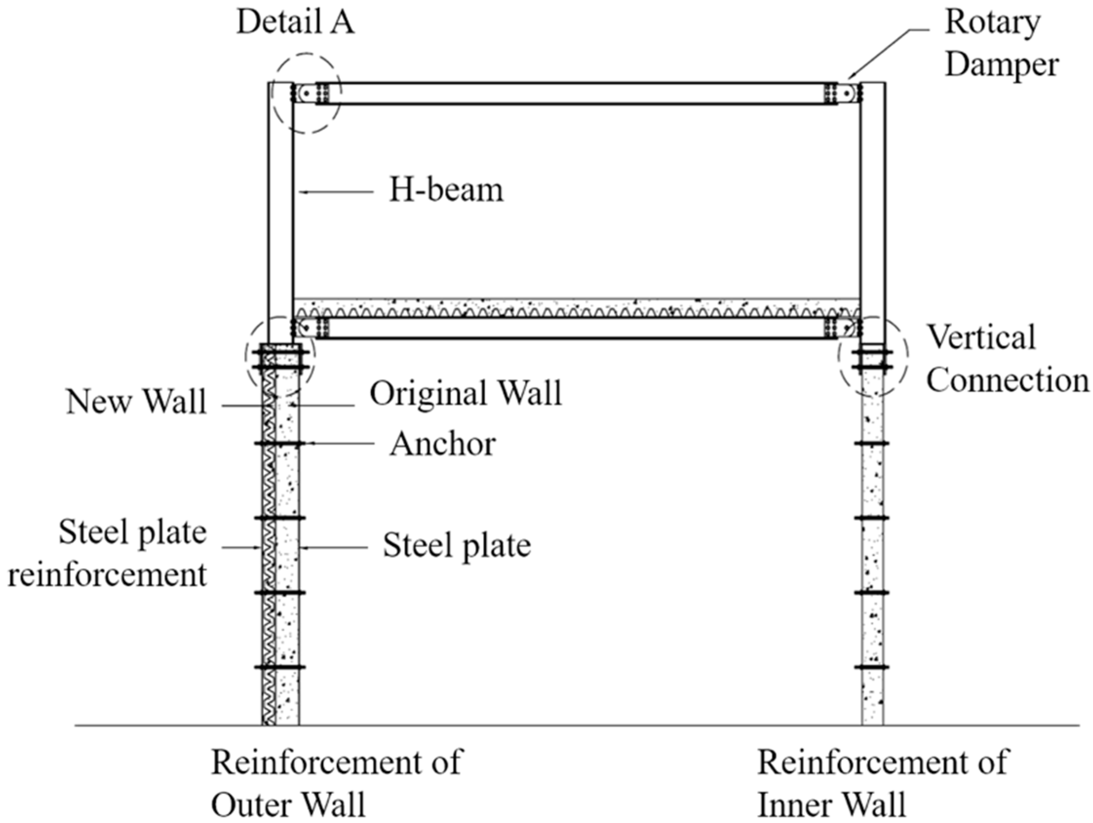
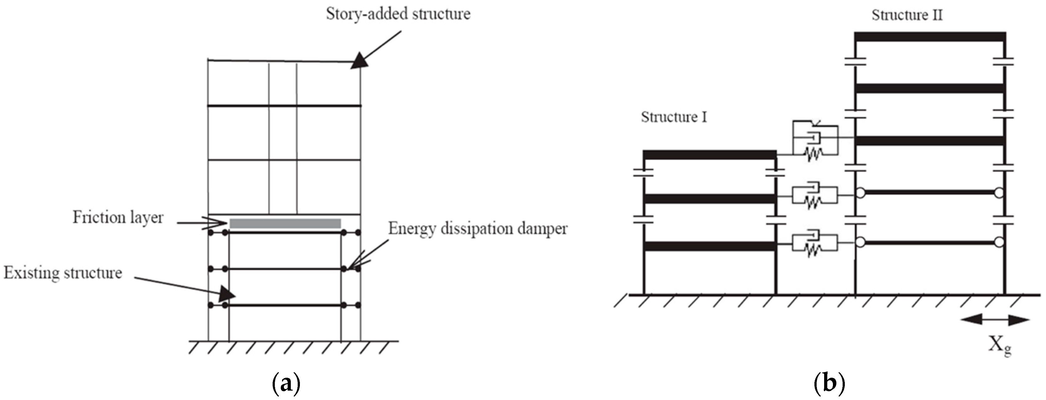
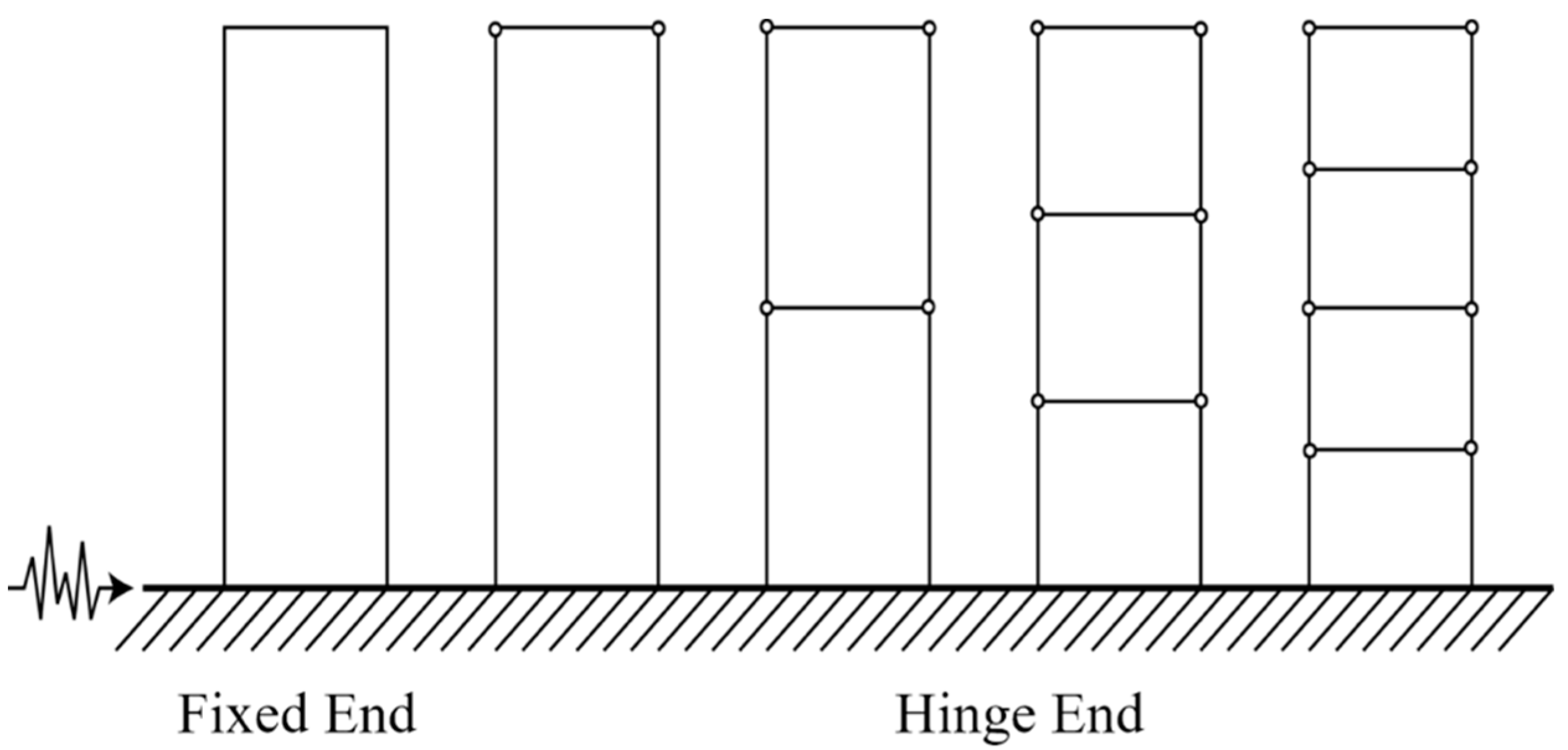
2. Proposal of Vertical Expansion Module Shape

A wall restraining effect can be obtained by using a vertical extension module between two walls that are not seismically designed (see Figure 1). It is also possible to add a bending moment, as described in Section 3, to the end of the cantilever wall. The shape of the proposed vertical expansion module is shown in Figure 3.
As shown in Figure 3, the vertical extension module of this study combines the upper end of the wall of the existing structure and the lower end of the column of the stretched structure. At least two columns extending in the longitudinal direction of the wall and an upper beam in which two columns of the expansion and contraction structure are movably coupled. As rotation between the column and the beam may occur, due to the lateral behavior of the constructed column, a friction pad is mounted on the surface where the sliding occurs, as shown in Figure 4. It also includes a device to prevent angle changes between the wall and the beam.
In order to completely restrain the rotation of the wall, the bending moments generated in the beams and columns of the vertical axis module occur at the same magnitude as the bottom wall moment. Therefore, when a steel frame is used, high rigidity is required, and the size of the steel frame increases. Additionally, when the top of the bearing wall is constrained, the bending strength in the out-of-plane direction cannot be ignored. Therefore, it is necessary to reinforce the wall (as shown in Figure 5), as the wall must ensure the flexural strength.
However, it is possible to reduce the magnitude of the bending moment applied to the beam by providing a slip at a designed bending moment, through the installation of a rotary friction damper. Therefore, the joint between the slab and the beam installed with the rotating friction damping device can be modeled as a kind of moment hinge. In spite of this, if the moment required for the steel frame is insufficient, it can be solved by replacing the steel frame with a pre-cast slab.

3. Numerical Analysis

3.1. Single Degree of Freedom System Numerical Analysis and Results

In order to verify the proposed method, numerical analysis of the structure shown in Figure 6 was performed. The mass was 1000 tons, the secondary moment of the section X modulus of elasticity was assumed to be 8.0 × 10 10   N · m 2 , and the height was 20 m, with a damping ratio of 5%. The seismic load used in the analysis was the El Centro ground acceleration, with maximum acceleration of 0.348 g. We considered the cases where the end of the cantilever is free, fixed (where only horizontal displacement and no rotation occurs), a rotating-type attenuator, or a linear viscous attenuator (which considers friction-type damping). The linear viscosity coefficient was set to 8.0 × 10 9   N · s · m , and the T s l i p value, which indicates the slip limit as the bolt tightening force varies, was set to 10% of the maximum value of the moment required for the fixed end. Figure 6 shows the time histories of the displacement, base shear, and overturning moment. It can be seen that the rotary damper at the end was much more effective in reducing displacement, shear force, and moment, compared to just the free end and the fixed end.
In the case of the fixed end, the displacement response decreased significantly, but the base shear force increased, compared to the free end, and the overturning moment decreased. This means that, when fully connected to the top of the wall, the rigid joint effect increases the rotation restraint stiffness, and energy dissipation is not possible. In the case of using a damping device, friction damping showed better control effects than viscous damping. The second analytical model was set up with a height of 4 m, a mass of 30 tons, a column stiffness (EI) of 2564 kN · m 2 , and a damping ratio of 5%.
The supporting condition was fixed-end, and the cross-section of beams and columns consisted of W14 × 283 and W8 × 10, respectively. We used a time history analysis method considering an El Centro (1940, NS) earthquake with a maximum acceleration of 0.342 g. In this case, an analysis was carried out according to the difference of joint hinge models. The structural analysis results were expected to vary, depending on the boundary conditions of the joints, and the bilinear hinge joints were modeled, and the joints were fixed and rotated. In the rotational stiffness analysis model, the plastic hinge generated in the structure by the lateral load was modeled by controlling the yield moment of the hinge. For this purpose, non-linear pushover static analysis was performed, in order to determine the yield moment ( M u ) of the member by the lateral load. The response of the system, according to the rotation rate of the hinge, was examined by setting the ratio (δ) of the yielding moment ( M h ) of the hinge to the yielding moment ( M u ) to 1, 0.5, 0.1, 0.05, or 0.01. The yield moment ratio (δ) is shown in Equation (1). According to the equation, for the fixed end, δ is 100, while that for the rotating end is 0.
δ = M h M p × 100
The non-linear static analysis and the time history analysis were performed to compare the responses generated by the behavior of the beam-column joint hinge and to verify the control performance of the damper when a seismic force was applied to the elasticity single-degree-of-freedom system. In order to determine the yield moment ratio (δ) of the damping device with the optimal control effect, the change of the displacement response and the base shear force with the decrease in the yield moment ( M u ) were compared while adjusting the hinge characteristics of the joint. Therefore, the plastic hinges and the yield moment ratio (δ) were calculated through the non-linear static analysis, which consisted of a fixed end, plastic hinge, and rotating end. If the frame is an elastic region, the stiffness of the joints will be the same as the stiffness of the fixed end; meanwhile, if a plastic hinge occurs, the stiffness of the rotating end is expected to be the same when non-linear behavior occurs.
It was assumed that the joint with the attenuator will have a characteristic that, when the hinge is rotated, the displacement (rotation) infinitely occurs without increasing the load (moment), unlike the usual plastic hinge. The hysteresis curves are shown in Figure 7, determined through non-linear static analysis through displacement control up to 0.2 m with different characteristics of beam-column connections.
This is equivalent to about 5% of the bending moment of 3368.15 kN · m , which is considered to be reasonable when modeling that the slip occurs at the moment expected by the damper. The frame with δ = 1 began to slip on the hinge when a moment of 33.68 kN m occurred in the beam, which corresponds to 1% of the flexural moment. When δ = 0.5, the hinge yielded at 16.84 kN · m , 0.5% of the plastic moment. The static non-linear analysis on the parameter δ of the joint hinge can be used to verify the validity of the proposed column–beam joint damping modeling. By applying this method, it is possible to evaluate the control performance of a steel frame model equipped with a damping device.
Figure 8 shows the displacement response time histories of the system with elastic behavior by fixed joints and the time history analysis of the inelastic behavior due to yielding of the hinge. Unlike elastic systems, inelastic systems can be seen to show static deformation after yielding.
The fixed-end system with elastic behavior was distributed symmetrically on the horizontal axis with zero displacements. On the other hand, it can be seen that the hinge system yielded by the earthquake load exhibited an asymmetric response distribution on the horizontal axis due to inelastic behavior. This is because part of the structure was damaged and static deformation occurred; then, the damage is repeated and vibrates around the new equilibrium position.
Figure 9 shows the results of the analysis of the end condition and the δ-time history of a single-story steel frame with a period of 1.14 s. As shown in Figure 8, when the moment exceeding the yield moment was generated at the fixed end beam-column joint, the hinge rotated at a constant moment. Therefore, it can be seen that the dissipation of the input energy was generated through the rotation of the joint hinge, and thus, the displacement response was reduced. However, it is expected to increase again when δ is greater than 0.5. In the hinge state of the graph, the displacement response was also significantly increased.
Figure 10 shows the time histories for the base shear of the system with fixed end, Hinge end, and δ = 5, 1, and 0.5 joint hinges. It is shown that the maximum base shear force was shown at the fixed single point, and the response decreased when δ became 1, like the displacement response. Further, in the system in which δ was smaller than 1, the base shear force gradually increased until the end became a hinge. It was also considered that the response control effect arose because the energy was dissipated while the joint hinge rotates due to the horizontal displacement of the structure. In the case of a single-layer structure with a period of 1.14 s, the best response reduction effect was obtained when the joint hinge yielded at a moment of 1% of the plastic moment of the fixed end.
Figure 11 shows the load–displacement hysteresis curves using the displacement and bottom shear force of the analytical model. As shown in Figure 11a, the hinged end of the joint had a linear hysteresis curve, due to the very small rotation caused by the seismic load, which means that little energy was dissipated in the hinge. Figure 11b considers a system which has a hinge for which δ is 5. It seems that rotational friction occurred when the joint exceeded 5% of the plastic moment. This shape is due to the fact that the energy dissipation due to yielding was not performed smoothly, as many parts of the structure behave in the elastic region. Figure 11c,d shows that the energy was dissipated enough by rotating the hinge repeatedly, due to the earthquake load, when δ = 1 and 0.5.
Table 1 shows the results of time history analysis, according to the hinge condition of the joint. Plastic hinges were generated in the plastic moment of the beam when the joint was fixed, and the yielding moment of the hinge decreased as the diameter of δ became smaller. The maximum base shear force due to seismic loading decreased sharply when δ was less than 5. The maximum displacement response decreased when δ was less than 5, increased at δ = 0.5, and the maximum displacement occurred when the joint was rotating.
Figure 12 shows the maximum base shear force and maximum displacement response according to δ. When δ is 100, the joint hinge is a fixed end; when δ is 0, it indicates a rotating end. The analytical model with a period of 1.14 s had the best response reduction effect when δ = 1 and when the yield moment of the hinge was defined as 1% of the plastic moment. When δ was less than 5, the response was abruptly changed.

3.2. Numerical Analysis and Results of Multi-Degree-of-Freedom System

In order to verify the seismic response reduction effect of the proposed control system, through an analytical study on seismic strengthening measures with a beam-column joint damper installed at the lower end of the multi-degree-of-freedom structure, the analytical model was constructed as follows. In this study, MATLAB was used for the analysis of the studied model to predict energy dissipation of a multi-column building. First, the pre-reinforcement structure is a single-story steel frame with a span of 6 m and a height of 18 m, and columns and beams with sections of W10 × 100 and W14 × 283. The mass was 5 tons, the stiffness was 213.42 kN · m 2 , the cycle was 1.41 s, and the damping ratio was 5%. Then, 1, 2, and 3 beams were added to the column at equal intervals to add degrees of freedom of the system. The beam and column joints of the slab modeling with dampers are defined as moment hinges. Finally, the seismic response was analyzed by non-linear static pushover analysis and non-linear time history analysis of each model with an added slab having a damper. As a result, the response reduction effect of the system, according to yielding of the joint-type damper, was examined. Figure 13 shows the basic model for the structural analysis, considering the end condition of column–beam and the yield moment ratio δ of the hinge, and compares the response changes according to the added degrees of freedom.

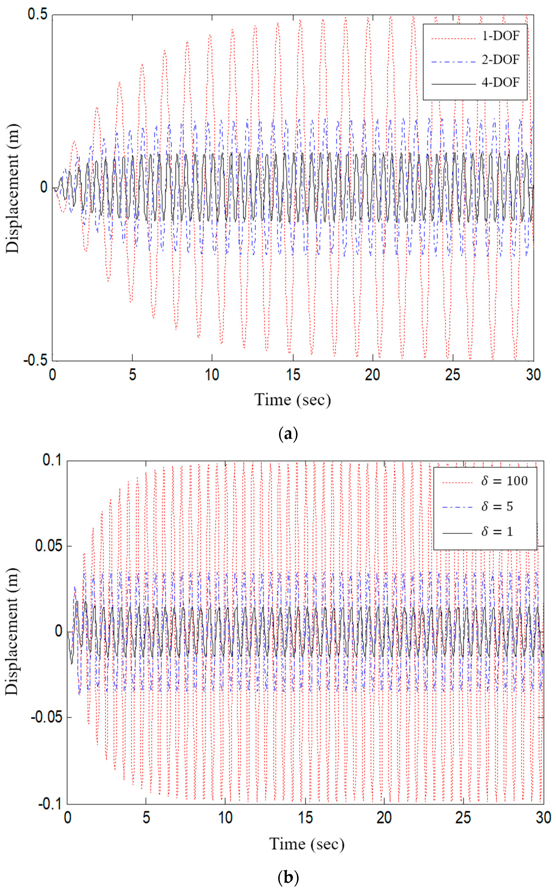
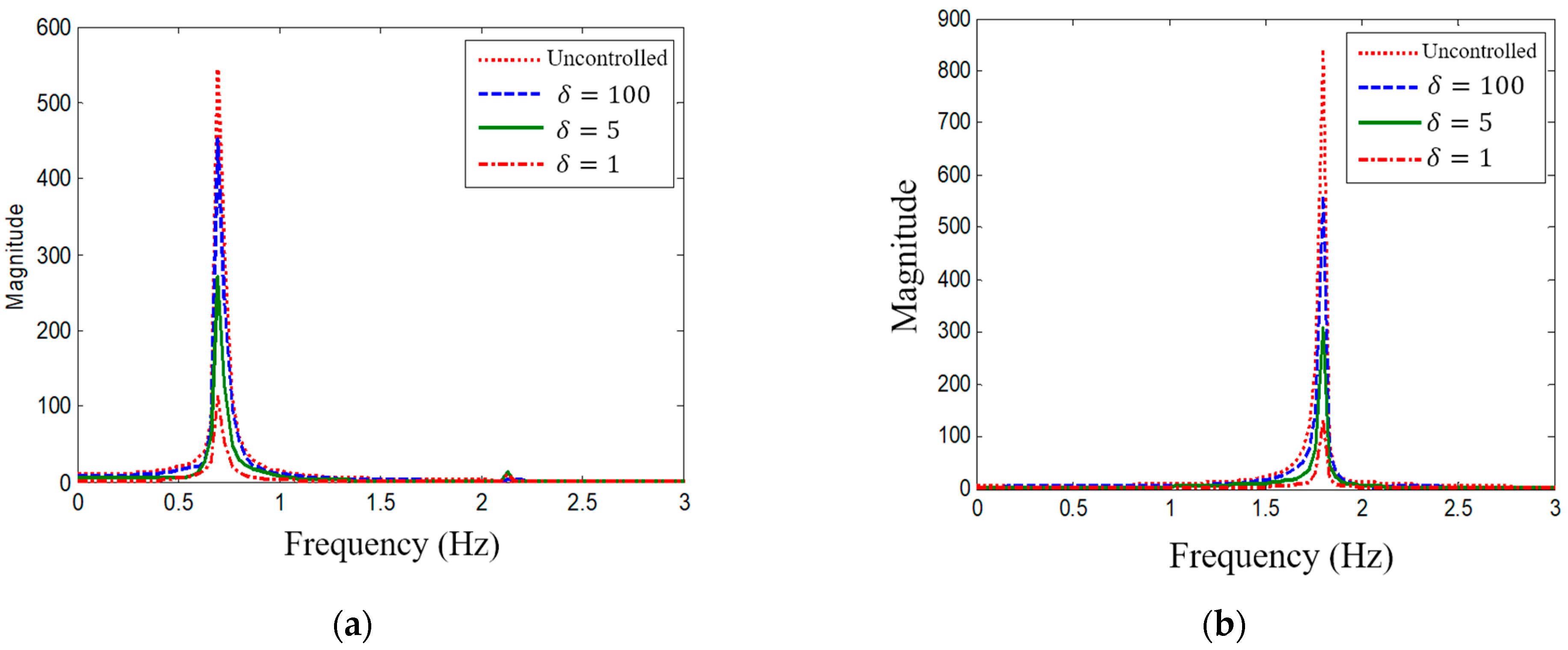
3.2.1. Multi-DOF Structure Response to Harmonic Load

An analytical model was designed to confirm the moment–hinge behavior response when the beam-column connection is fixed and when a damper is installed. The analytical model was grasped by modal analysis and fitted such that the first natural frequency is the same. The time history analysis was performed using the harmonic load with a maximum acceleration of 1 m / s 2 amplified response at the resonance of the structure, comparing the results obtained with a varying number of degrees of freedom and change of δ.
Figure 14a shows the result of the harmonic load time history analysis for the increased degrees of freedom model by adding an inter-layer slab to the unreinforced terminal guided steel frame, showing the displacement response for the number of degrees of freedom when the beam-column joint is fixed.
It can be seen that the maximum displacement response decreased steadily as the degrees of freedom increased from the amplified displacement response to the middle layer reinforcement when resonance occurs in each degree of freedom structure. This is because the lateral stiffness of the structure increases as the degree of freedom increases. Figure 14b shows the harmonic load displacement response according to the yield moment ratio δ of the joint hinge of a 4-DOF structure with three slabs added. It can be seen that the displacement response decreased significantly when yielding at 5% and 1% of the joint plastic moment, compared with when the joint is fixed.
After resonance, the displacement response was dominated by the primary mode and the secondary and tertiary modes had little effect. As with the previous analysis results, the response decreased in all frequency bands as the δ value of the joint hinge became smaller. When δ was 10, 5, and 1, the maximum response at resonance was reduced to 20%, 48%, and 81%, respectively, compared to the system without a rotary damper.
Figure 15 shows the FFT results for the single-degree-of-freedom model, in terms of the harmonic load and the top layer acceleration response for the four-story structure. As with previous displacement responses, it can be seen that the maximum acceleration response decreased as δ of the joint hinge decreased. The maximum response of the system with δ = 10, 5, and 1 was reduced to 30%, 65%, and 87%, respectively, compared with the non-control system response. It can be seen that, when the rotary damper was installed, the control effect due to yielding of the joint hinge after the displacement and acceleration response of the resonant structure reached steady state.

3.2.2. Structural Response to Seismic Load

The yield strength ratios of the joint moment hinges were defined as 100 (fixed end), 10, 5, 3, and 1, and the non-linear time history analysis was performed by adding slabs connected to the columns with rotary dampers. Table 2 shows the maximum floor displacement response and maximum base shear of the steel moment frame model with 5% damping ratio, due to the El Centro earthquake. The natural frequencies of the structures were added before reinforcement and the first, second, and third floors were 1.4, 0.81, 0.64, and 0.56 s, respectively. The effect of δ on the non-linear time history analysis results indicated that the maximum displacement response under all degrees of freedom decreased as δ decreased, and the maximum displacement response tended to increase again when δ was smaller than 3. Therefore, in the case of the hinge with rotating joint, compared to the single hinge, the energy was dissipated by rotation and the displacement response is reduced. However, when the hinge yielded at too low a bending moment, the displacement response was increased. The base shear force increased in proportion to the number of slabs but decreased as the yielding moment of the hinge decreased. This can be explained by the joint hinge not being able to transmit the moment when a lateral load acts on the structure.
Figure 16 shows the top-layer displacement response (according to δ) of the single-, two-, three-, and four-story analytical models for El Centro ground motions. All analytical models had a damping ratio of 5% and the natural frequencies of the structures were 1.4, 0.81, 0.64, and 0.56 s, respectively. Regardless of δ, as the number of slab connections for reinforcement increased, the maximum displacement response naturally decreased.
The influence of δ on the number of degrees of freedom of the analytical model is as follows. For the single-story structures before reinforcement, the minimum displacement response was 0.195 m when δ = 3. The two-degree-of-freedom analysis model with one slab was found to have the largest displacement response as δ increased. The analysis models for 3 and 4 degrees of freedom showed that the response decreased until δ = 5, and then increased again after 5. When the yield moment of the joint hinge corresponded to 5% of the plastic moment of the beam, it was deemed to have the optimum energy dissipation capacity, due to the deformation caused by the seismic load.

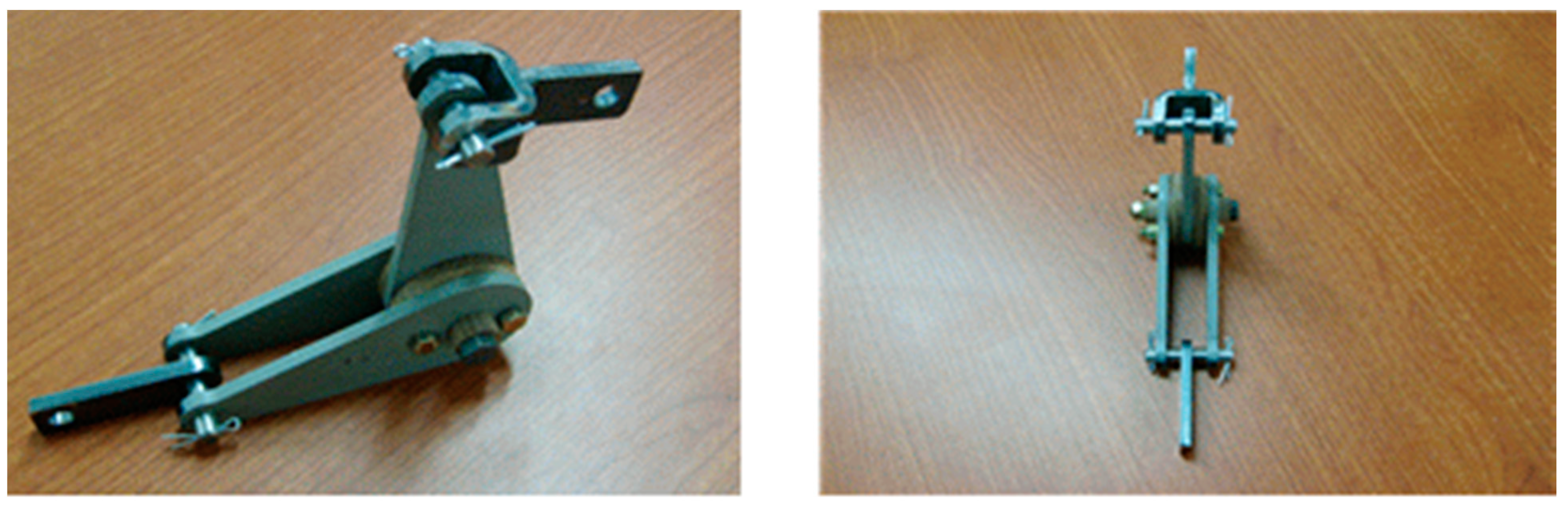
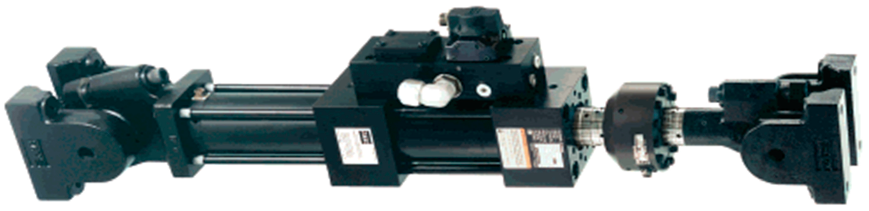
4. Experiment of Energy Dissipation Capacity of Rotary-Type Damping Device

It is necessary to confirm whether the operation principle of the rotary-type friction damper is the same as the numerical analysis results. For this purpose, a compact damper was installed horizontally on a reaction wall and external forces were applied cyclically in the horizontal direction, with frequency, displacement, and load as parameters. As a result, the force–displacement history curves of the damper were obtained.

4.1. Experimental Model and Method

As shown in Figure 17, the rotary-type damping device used in the experiment combined the three steel plates and the friction pad with the tightening force of the high-strength bolts. Both ends of the iron plate were fixed to the force-applying device and the reaction force wall. It was designed to rotate like a hinge when a moment larger than the frictional force of the joint is generated around the high-tension bolt at the center of the damper.
The rotary-type damper used in the experiment was smaller than the actual one. The maximum torque was 4500 N-mm, and the frictional force of the center hinge could be adjusted by tightening the bolt. Therefore, it is possible to set the energy dissipation capacity of the damping device to the design capacity, and it is also advantageous to adjust the damping force according to the characteristics of the structure and the load, even when installed in the real structure. Even if the damping system is installed vertically, the basic mechanical behavior is the same, such that it can be installed between a column and a beam joint. Therefore, it can be installed at the part where deformation occurs in the structure, such that the damping force is concentrated, and the deformation is reduced. As it can be installed directly on the joint, it is not necessary to use an auxiliary mechanism and it is possible to secure more space inside the structure. In this paper, a dynamic actuator with a maximum stroke of 150–200 mm and a maximum force of 50 kN was used, as shown in Figure 18, to generate an external force through displacement control.
The specimens were designed so that the deformation of both ends was suppressed and rotated, and all deformation was made on the friction surface provided with the friction pad. Experiments were carried out 100 times using a cyclic load, according to the variable through the actuator (see Table 3). Experimental parameters were divided into excitation frequency, excitation displacement, and bolt tightening force. In this experiment, the results of the three variables were obtained. First, in order to understand the response characteristic, according to the excitation frequency, the actuator displacement was ±4 mm, the tightening force of the bolt was fixed at 600 N-mm, and the excitation frequency varied from 0.5 Hz to 4 Hz. Next, to investigate the response characteristics of the damping device, according to the change of displacement, we set the excitation frequency to 0.5 and 2 Hz, fixed the bolt tightening force to 1400 N-mm, and adjusted the displacement. Finally, in order to examine the response characteristics, according to the tightening force of the bolt, experiments were performed by adjusting the tightening force of bolts up to 600 to 4500 N-mm, keeping the displacement and frequency fixed.

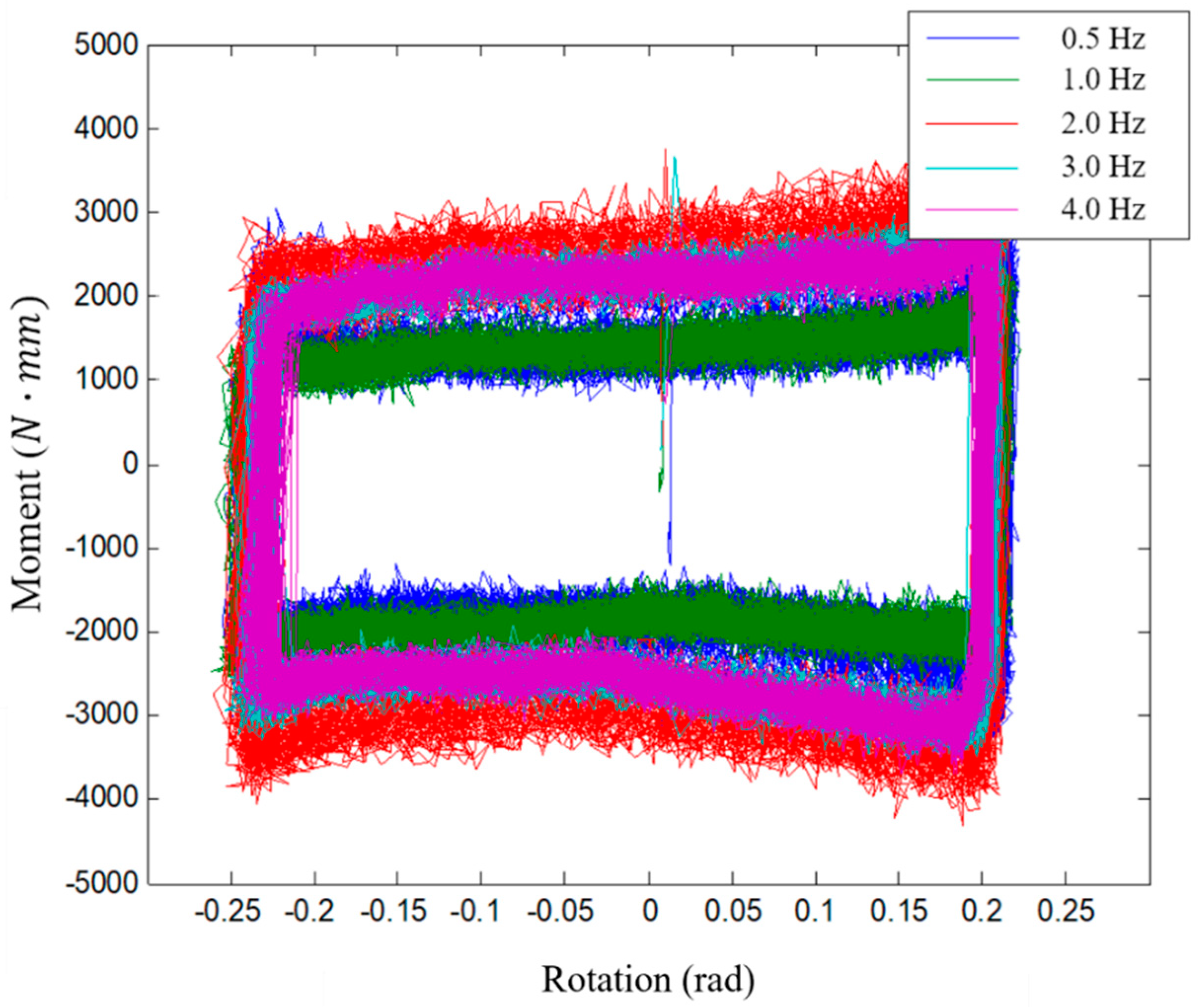
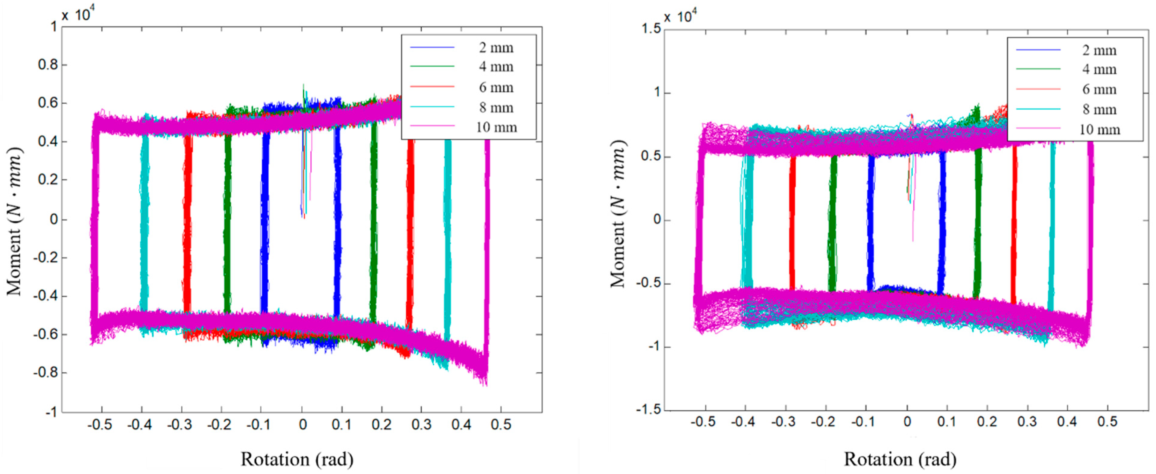
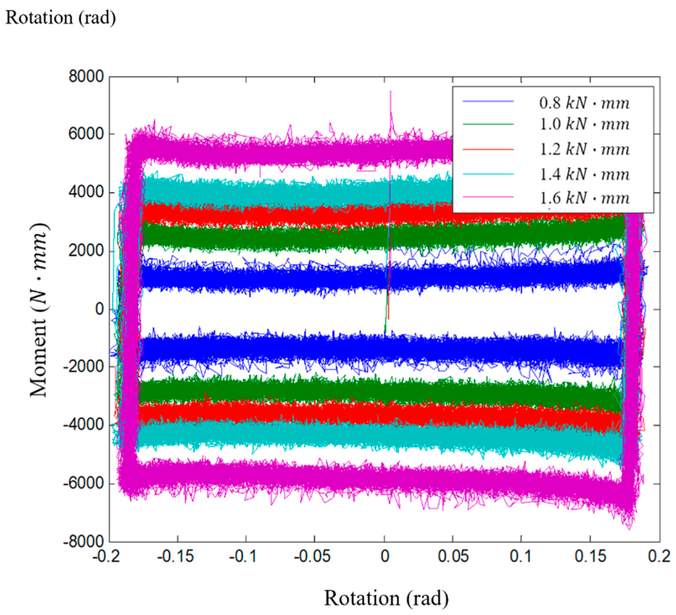
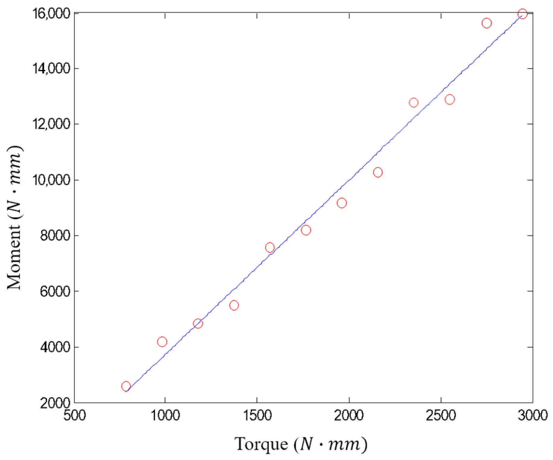
4.2. Experimental Results and Variable Analysis

In this experiment, the load measurement direction of the load cell and the rotation center of the damping device are not always perpendicular. As shown in Figure 19, the rotational angle of the attenuator changes the length of the angle of rotation ( θ ) and vertical height ( h a ). Therefore, the moment acting on the rotating friction damper is calculated by using the correction equation and the vertical deformation ( h a ) and rotation angle ( θ ) of the attenuator. Equation (2) is the moment of the friction surface generated by the external force on the damper.
M f = F × h a
where Factual is the force transmitted to the damping device through the actuator, and the force F acting on the friction surface of the actual damper has the relationship of Equation (3):
F a c t u a l = F × cos θ
where θ can be inferred using the direction of the force and height h a :
θ = tan 1 ( d 1 + Δ x h a )
Further, the length h a can be determined by the following Equation (4):
h a = d 2 2 ( d 1 + Δ x )
Therefore, the moment on the friction surface of the damping device can be obtained from Equation (6) using Equations (3)–(5):
M = F cos ( tan 1 ( d 1 + Δ x h a ) ) h a
Figure 20 shows the relationship of the moment–rotation angle of the friction damper to the excitation frequency. As shown in the figure, it can be seen that the magnitude of the maximum yield moment was almost the same, even if the frequency changed. However, LVDT was dropped as a setting after the 1 Hz frequency experiment, and the experimental setting was changed. As a result, the moment was shifted due to the difference in the value during the torque control, but the yield moment value was similar. Therefore, we found that the rotary-type damping device has a constant yielding moment, regardless of the excitation frequency.
Figure 21a,b shows the relationship between the moment rotation angles of the dampers and the displacement magnitudes. The yield moments of the rotating friction dampers were all the same, according to the same excitation frequency.
It can be seen that the dynamic characteristics of the rotary friction damper, according to the above frequency and displacement, regularly shifted in accordance with the magnitude of the tightening force of the bolt. Therefore, the relationship between the tightening force of the bolt and the friction surface is considered to be a very important parameter in designing the actual rotating friction damper. Figure 22 shows the response characteristics of bolts, with respect to the tightening force. As the tightening force of the bolt increases, the yield load increases linearly. Reduced or unbalanced load behavior did not occur during repetitive behavior. Based on these results, we found that the rotational torque of the tightening bolt force and the friction damper are linearly related to each other.
Figure 23 shows the result of the first-order interpolation with the rotation moment of each tightening force shown in Figure 22. As shown in the figure, the tightening force and the rotation moment have a linear regression relationship, where each torque produces a yielding moment with magnitude of 5 times. This clearly shows the correlation between the clamping force and the coefficient of friction of the pad. Therefore, if a friction damper of actual size is manufactured, the accurate friction coefficient of the pad and the maximum tightening force of the bolt will be important design factors.

5. Conclusions

In this study, a shape with a rotating-type damping device was proposed for a beam-column joint, in order to utilize a vertical extension structure as an earthquake resistance system.
As a result, it is possible to include functional elements different from the conventional method, which only increases the load. As the slab of the apartment before the shape suggestion does not constrain the rotational response of the wall, the bearing wall between the residence spaces behaves as a cantilever when the external force is applied in the long-side direction, and a very large displacement occurs as it goes to the upper side. Numerical analysis of the proposed vertical expansion module shows that the displacement, base shear force, and overturning moment can be significantly reduced by restraining the rotation with a rotary damper. Using the vertical expansion module proposed in this study, it is possible to reinforce the seismic performance of the structure by reducing the maximum displacement. The proposed design can be easily applied to high-rise structures, due to its small shape and simple structure. Additionally, by installing a pad on the damping device and adjusting the frictional force, constant seismic performance can be maintained even after completion of the construction. The seismic performance can be effectively reinforced, regardless of the natural period of the structure. In particular, it can be designed by adjusting the stiffness and damping effect of the enlarged structure, according to the magnitude of the frictional force.
In order to verify the proposed vertical extension module and rotary-type damping device, a single-degree-of-freedom static non-linear pushover analysis was performed by modeling with a rotating damping device at the joint. In order to verify the simulation, the correlation between variables was verified through actual experiments. The results of multi-degree-of-freedom simulation considering harmonic and seismic loads, and those obtained by comparison of the rotary-type damper revealed by the actual experiment were as follows:
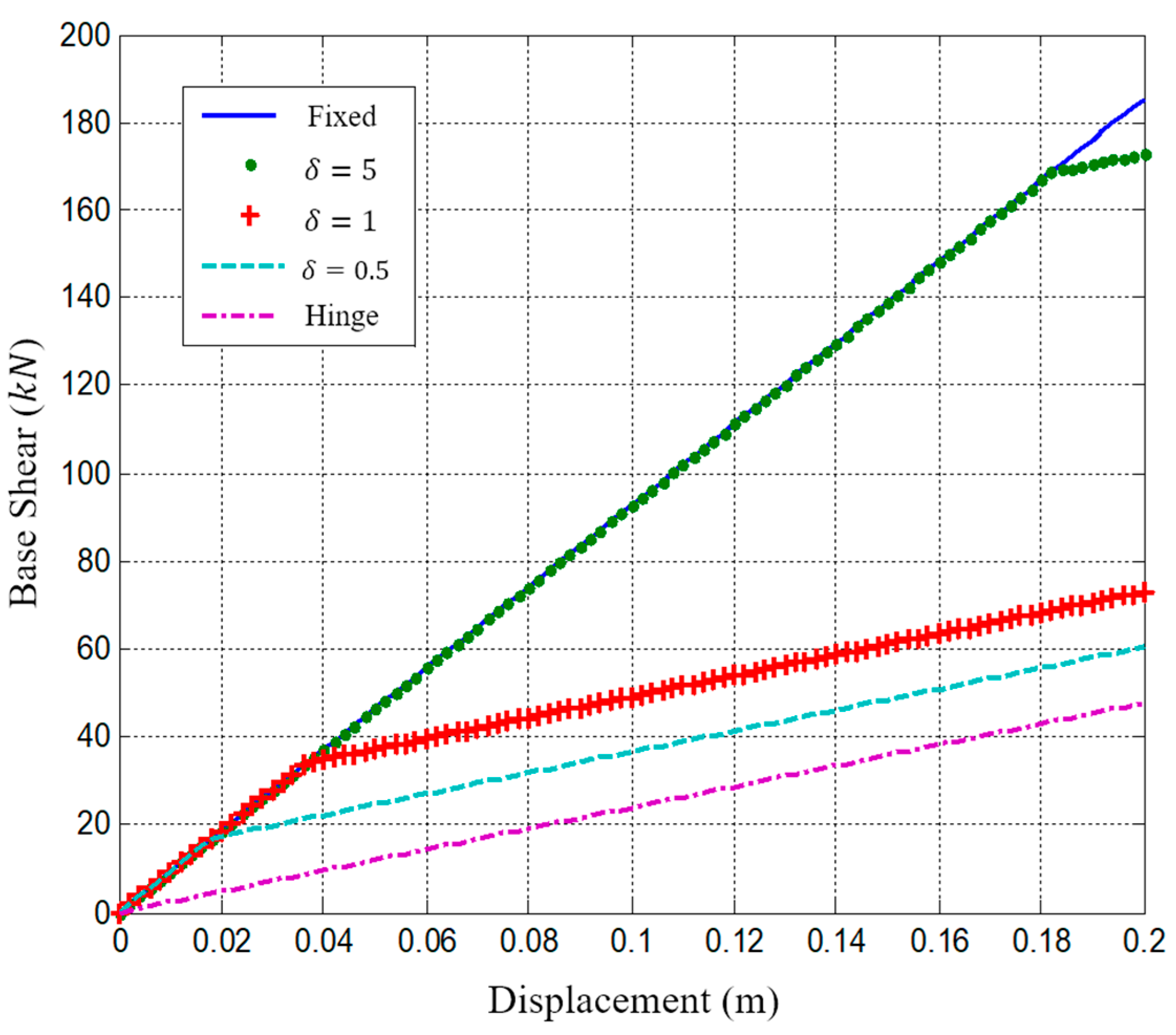
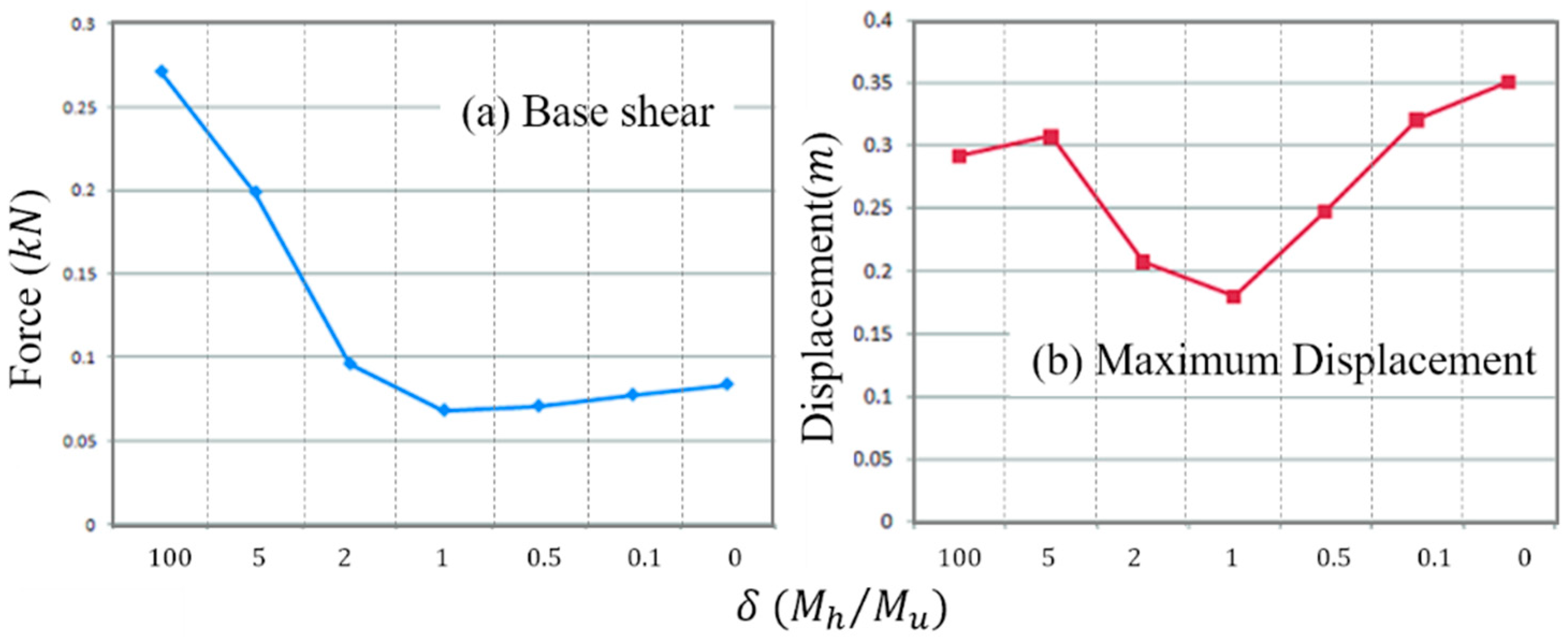
  • The rotary damper is more effective in reducing the displacement, shear force, and moment when the joint is free and fixed. In the pushover analysis of the system modeled by the moment hinge of the rotary damper of the joint, the best response reduction effect was obtained when the yield moment of the hinge was defined as 1% of the frame plastic moment, and when δ is less than 5.
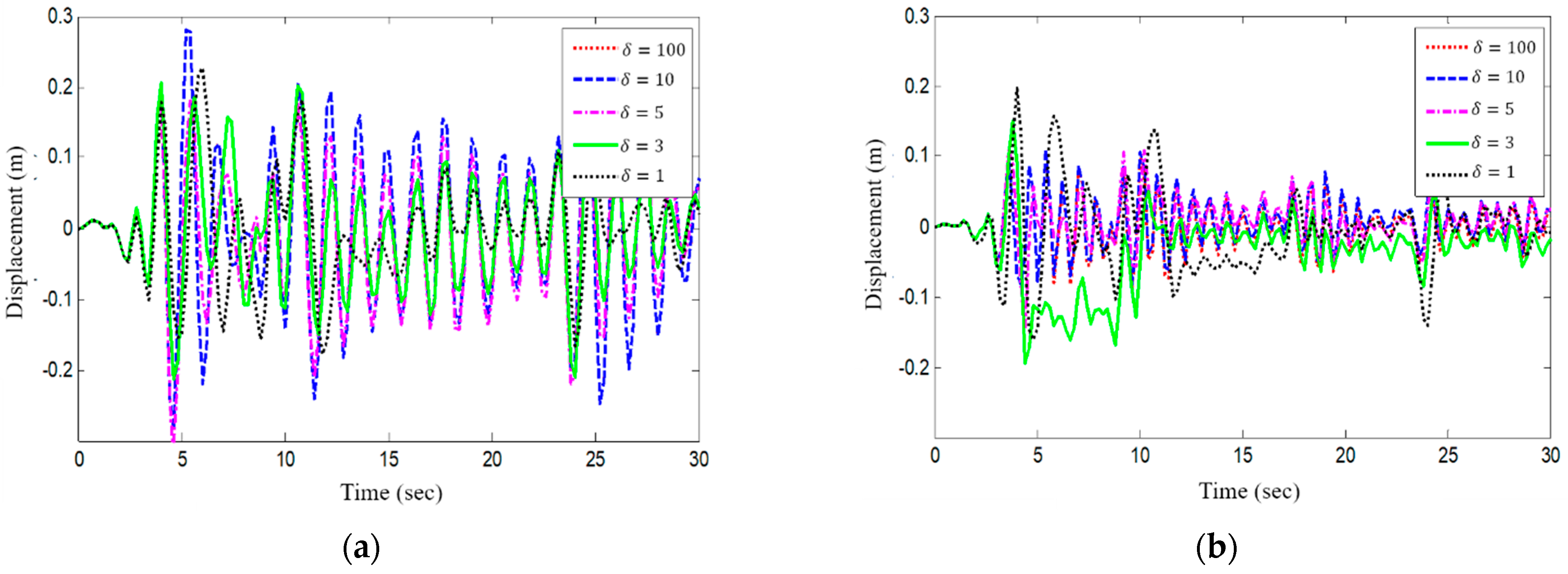
  • The time history analysis results for the harmonic load of the multi-DOF system showed that it is effective for the hinge to yield after the displacement and the acceleration response of the resonant structure to reach steady state.
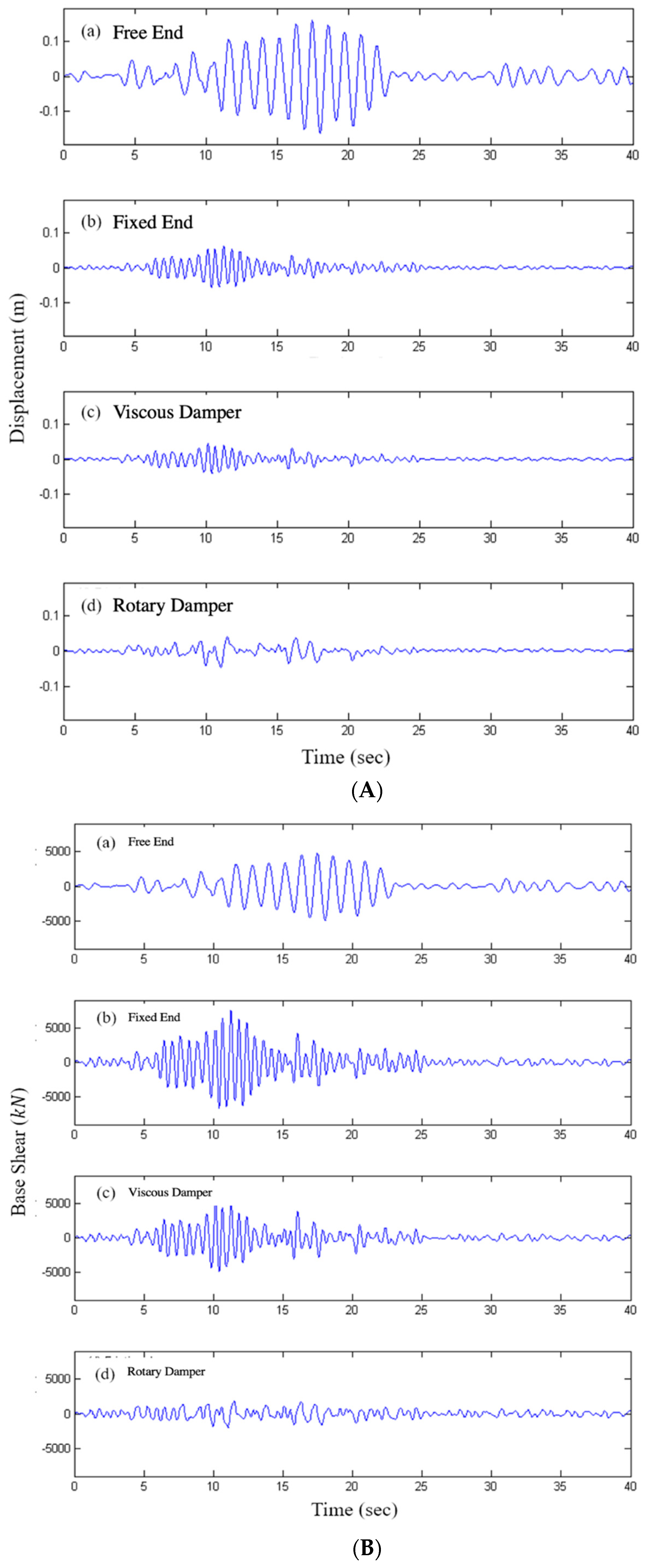
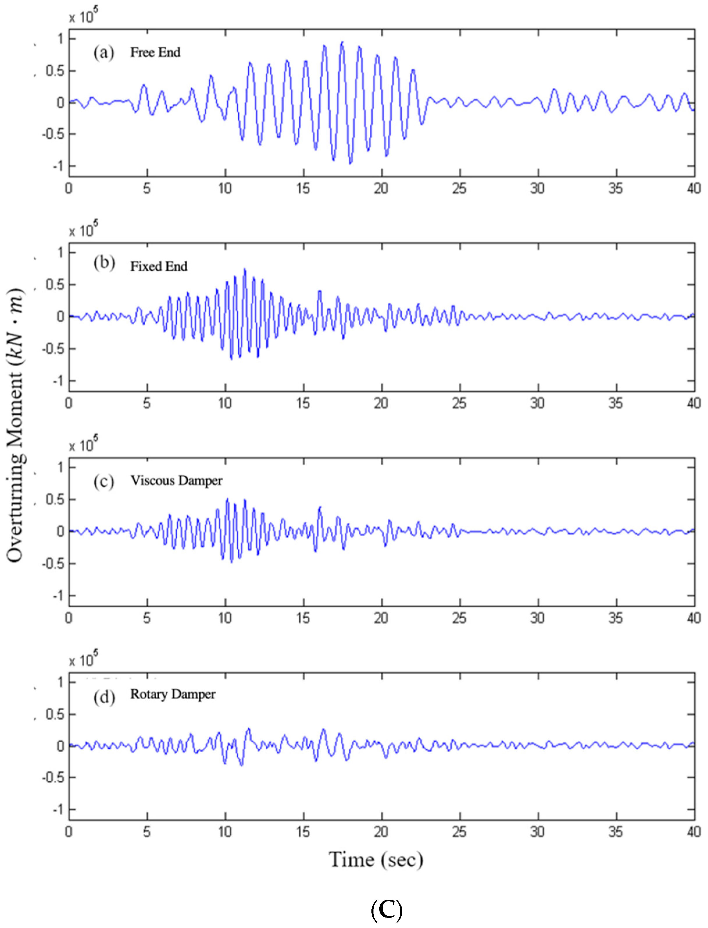
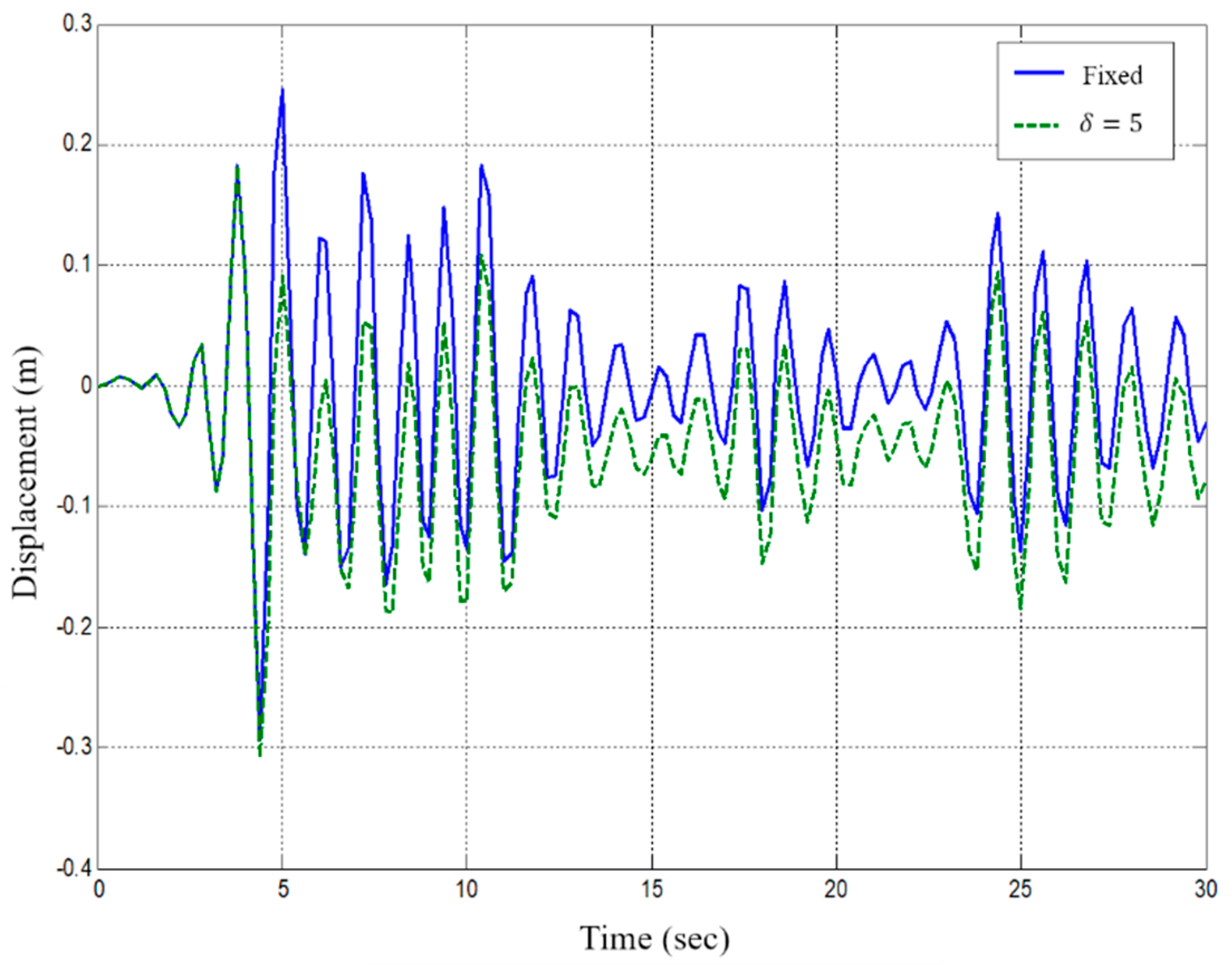
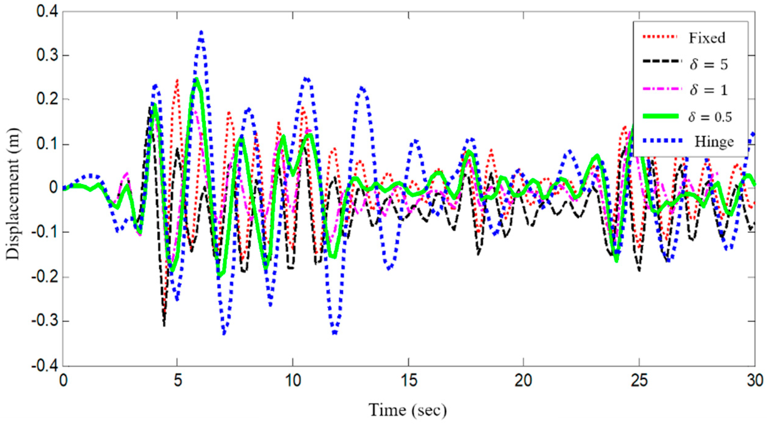
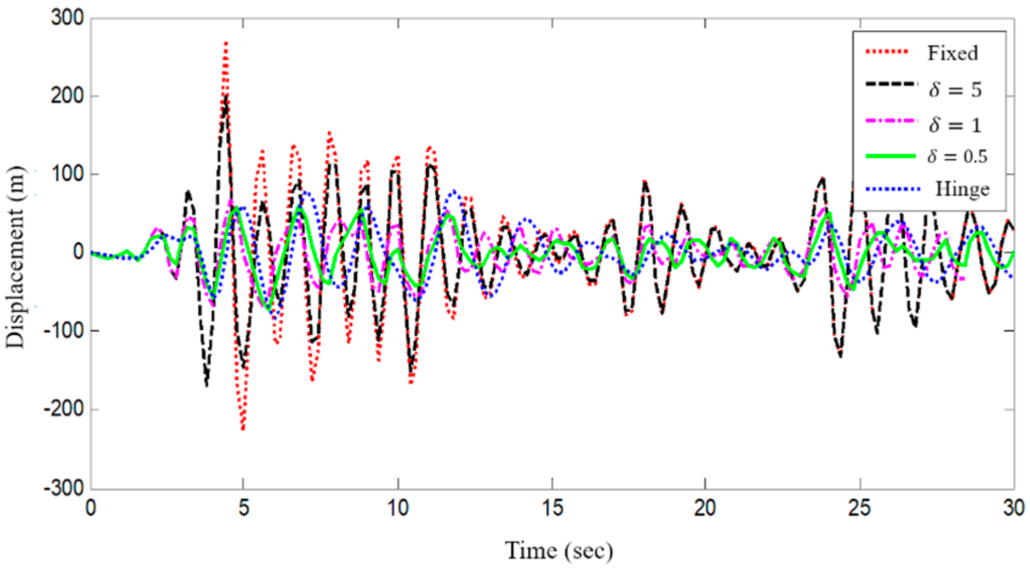
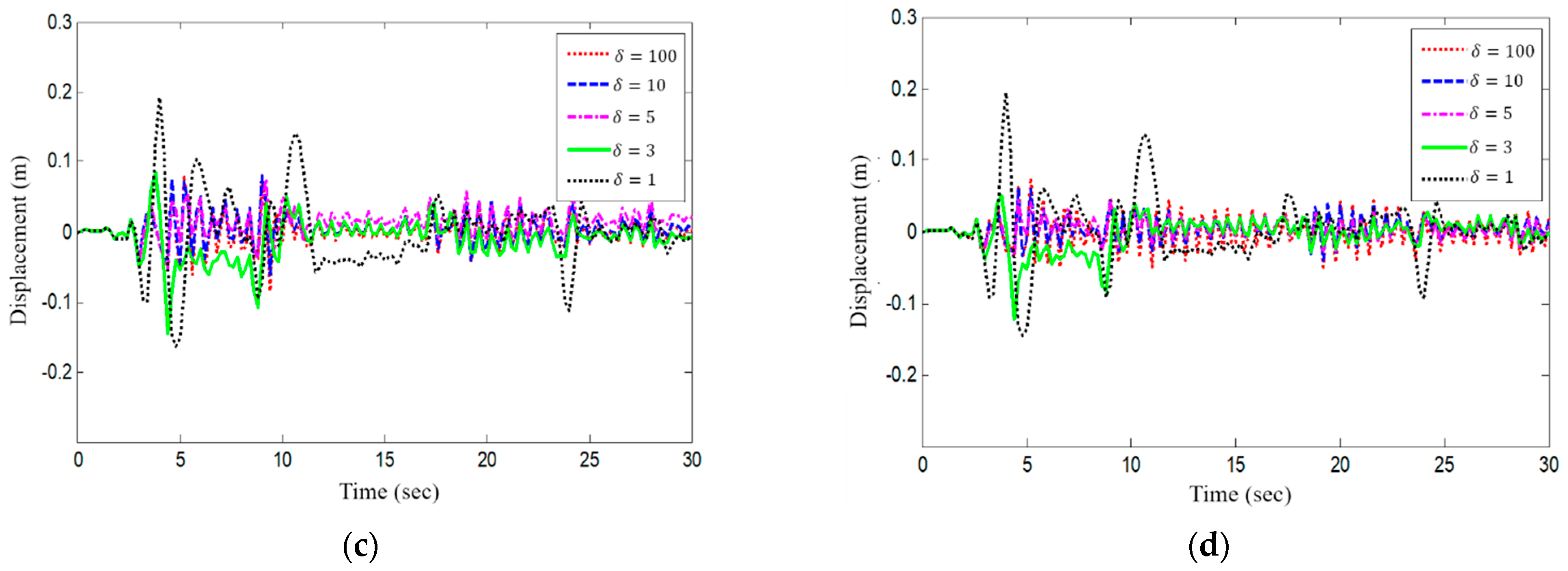
  • As a result of the non-linear time history analysis using data of the El Centro earthquake, the bilinear system with inelastic behavior, after the yielding of the hinge of the joint, showed an asymmetric displacement response that oscillates around the position deviating from the initial position, as the member was not restored after yielding. The displacement response was reduced by the energy dissipated by the rotation when the hinge end is at the end of the joint, but the displacement response increased when the hinge yields at a bending moment that is too small.
  • As in the previous pushover analysis, when the yield moment of the joint hinge corresponds to 5% of the plastic moment of the beam, it is deemed to have the optimum energy dissipation capacity, due to the deformation caused by the seismic load. By comparing the maximum base shear force and the maximum displacement response according to the value of δ, we confirmed that the optimum yield moment of the joint hinge of the analytical model is 1% of the fixed end.
  • In the multi-degree-of-freedom system with the slab connection added to the analytical model, the natural period of the structure became smaller, and the displacement response of the uppermost layer gradually decreased as the joint increased. The same phenomenon was observed for the general structure, indicating that the rotary damper does not affect the overall behavior of the structure. The maximum energy dissipation at the joint hinge occurs only under the occurrence of a large deformation, such as resonance through force-displacement history behavior.
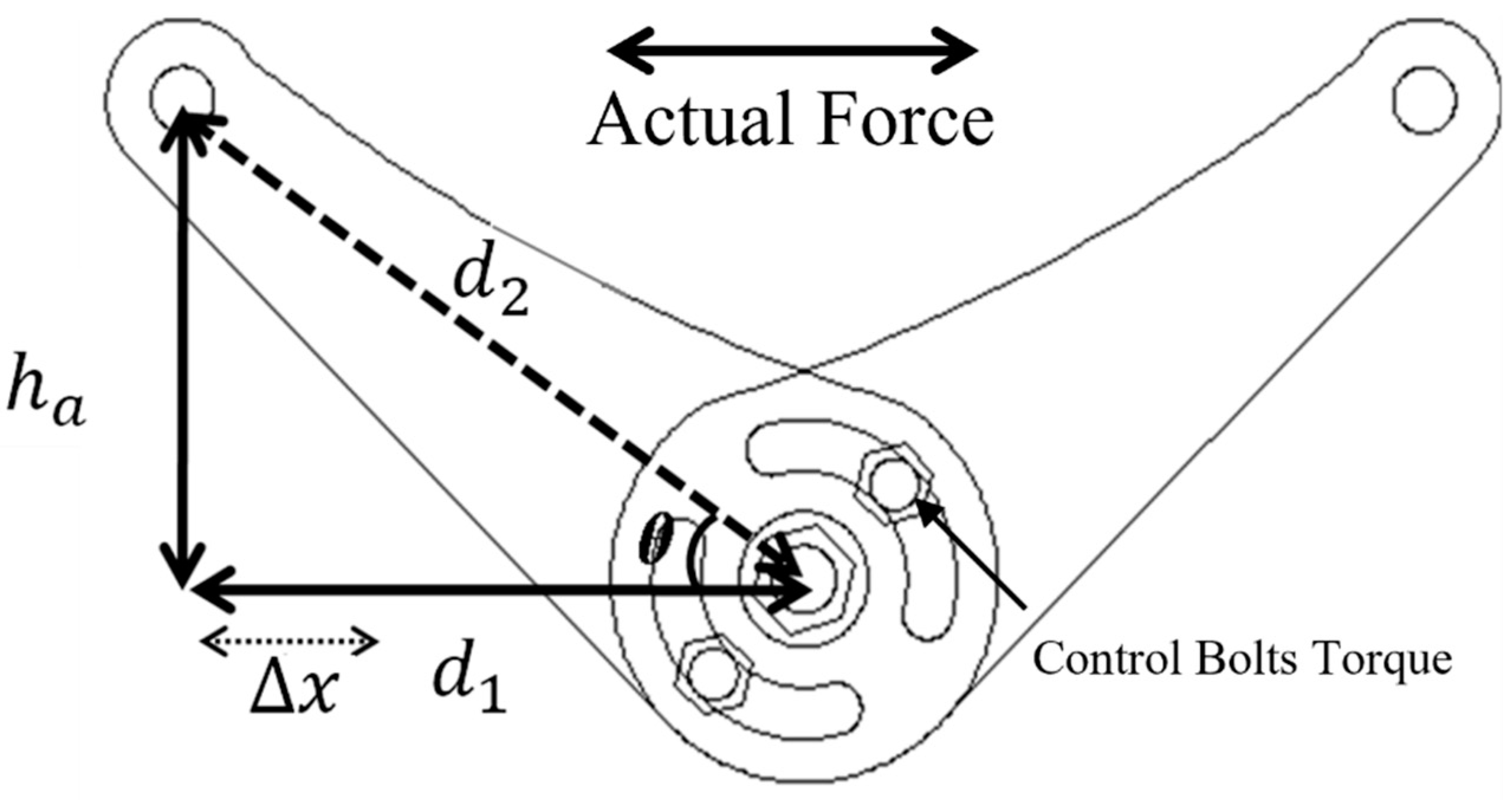
  • The rotary-type damper has a constant yielding moment without being influenced by the excitation frequency. Even if the displacement is changed, the yielding moment of the damping device is not affected by the excitation frequency. In further research, more cases would be tested to acquire more reliable results of this study for practical application to the buildings.
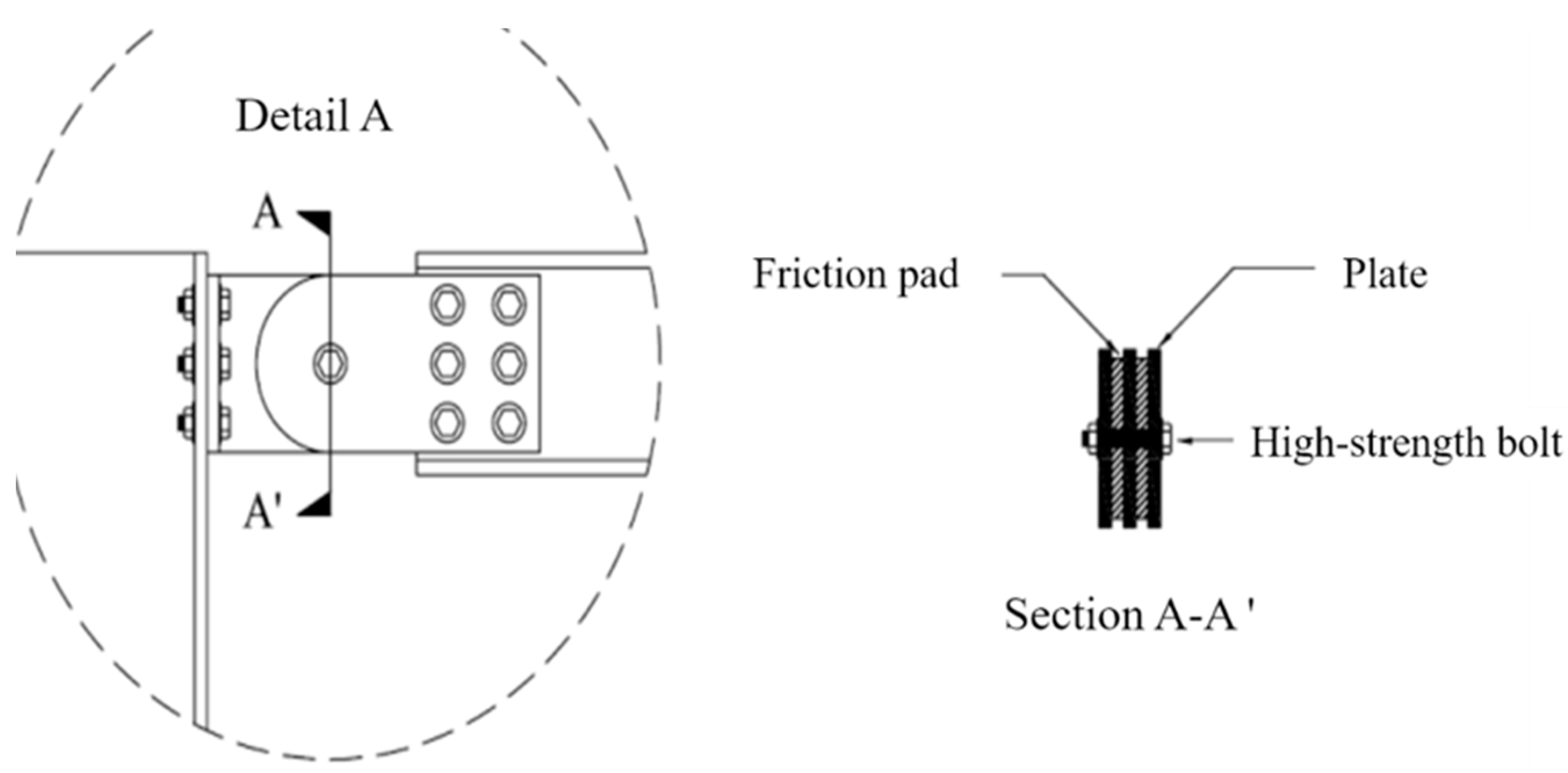
  • Furthermore, the yielding moment of the damping device increases linearly with the tightening force of the bolt. Thus, the relationship between the tightening force and the friction surface was determined to be a very important parameter in the design.

Author Contributions

Conceptualization, S.L. and S.N.; methodology, S.H. and M.-W.H.; validation, S.N., S.H. and S.N.; formal analysis, S.H., M.-W.H. and S.L.; investigation, S.H. and S.N.; resources, S.H. and S.L.; data curation, S.H. and M.-W.H.; writing—original draft preparation, S.H.; writing—review and editing, S.N. and S.L.; visualization, S.H. and M.-W.H.; supervision, S.L.; project administration, S.N.; funding acquisition, S.H. and S.L. All authors have read and agreed to the published version of the manuscript.

Funding

This work was supported by the National Research Foundation of Korea (NRF) grant funded by the Korea government Ministry of Education (No. NRF-2018R1A6A1A07025819 and NRF-2020R1C1C1005406).

Data Availability Statement

The data used to support the results in this research are included within the article. Furthermore, some of the data in this article are supported by the references mentioned in the paper. If you have any queries regarding the data, the data of this research will be available from the corresponding author upon request.

Conflicts of Interest

The authors declare no conflict of interest.

References

  1. Jeong, G.H.; Lee, H.S.; Hwang, K.R.; Kwon, O.-S.; Kim, S.-J. Seismic Fragility Analysis of High-Rise RC Box-Type Wall Building Structures. J. Earthq. Eng. Soc. Korea 2016, 20, 155–162. [Google Scholar] [CrossRef]
  2. Cho, W.-S.; Lee, S.-H.; Chung, L.; Kim, H.-J.; Kim, S.-J.; Yu, E.-J. Seismic Performance Evaluation of Reinforced Concrete Frame with Unreinforced Masonry Infill. J. Archit. Inst. Korea Struct. Constr. 2012, 28, 31–41. [Google Scholar]
  3. Hur, M.-W.; Lee, S.-H.; Chun, Y.-S. Vibration Control of the Framed Building Structures Using KGDS System with Iso-tropic Damping Devices. J. Korea Inst. Struct. Maint. Insp. 2015, 19, 52–59. [Google Scholar]
  4. Seismic Retrofitting and Remodeling Research Center. Grading of Seismic Performance and Development of Seismic Strengthening Design Methods for Remodeling of Deteriorated Apartment Houses. In National Research Laboratory Final Report; Dankook University: Yongin-si, Korea, 2007. [Google Scholar]
  5. Bae, C.-H.; Kim, Y.-W.; Lee, S.-H.; Park, Y.-P. Shaking Table Test of a Full Scale 3 Story Steel Frame with Friction Dampers. Trans. Korean Soc. Noise Vib. Eng. 2007, 17, 862–873. [Google Scholar]
  6. Chun, Y.; Hur, M. Exo-type damping system with isotropic dampers. In Advances in Civil, Architectural, Structural and Constructional Engineering: Proceedings of the International Conference on Civil, Architectural, Structural and Constructional Engineering, Dong-A University, Busan, Korea, 21–23 August 2015; CRC Press: Boca Raton, FL, USA, 2016; pp. 281–284. [Google Scholar]
  7. Council, B.S.S.; Council, A.T. NEHRP Guidelines for the Seismic Rehabilitation of Buildings; Federal Emergency Management Agency: Washington, DC, USA, 1997; Volume 1. [Google Scholar]
  8. Paulay, T. Coupling Beams of Reinforced Concrete Shear Walls. J. Struct. Div. 1971, 97, 843–862. [Google Scholar] [CrossRef]
  9. Bielak, J. Dynamic behaviour of structures with embedded foundations. Earthq. Eng. Struct. Dyn. 1974, 3, 259–274. [Google Scholar] [CrossRef]
  10. Macrae, G.A.; Kimura, Y.; Roeder, C. Effect of Column Stiffness on Braced Frame Seismic Behavior. J. Struct. Eng. 2004, 130, 381–391. [Google Scholar] [CrossRef] [Green Version]
  11. American Society of Civil Engineers. Seismic Evaluation and Retrofit of Existing Buildings; American Society of Civil Engineers: Reston, VA, USA, 2017. [Google Scholar]
  12. Bruneau, M.; Uang, C.-M.; Whittaker, A. Ductile Design of Steel Structures; McGraw-Hill: New York, NY, USA, 1998; Volume 389. [Google Scholar]
  13. Oh, Y.-H.; Han, S.W.; Lee, L.-H. Effect of boundary element details on the seismic deformation capacity of structural walls. Earthq. Eng. Struct. Dyn. 2002, 31, 1583–1602. [Google Scholar] [CrossRef]
  14. Hwang, J.-S.; Park, S.-C.; Kang, K.-J. A study on the hysteresis properties and mathematical model of Kagome truss damper. J. Archit. Inst. Korea Struct. Constr. 2013, 29, 21–29. [Google Scholar]
  15. Hyun, C.-K. Structural Design for Remodeling in Vertical Extension of Apartment Building. Mag. Korea Inst. Struct. Maint. Insp. 2014, 18, 9–13. [Google Scholar]
  16. Oh, S.-H. Effective Seismic Structural System for Vertical Extension Remodeling of Apartment. Mag. Korea Inst. Struct. Maint. Insp. 2014, 18, 3–8. [Google Scholar]
  17. Li, H.; Wang, S.-Y.; Song, G.; Liu, G. Reduction of seismic forces on existing buildings with newly constructed additional stories including friction layer and dampers. J. Sound Vib. 2004, 269, 653–667. [Google Scholar] [CrossRef]
  18. Li, H.-N.; Yin, Y.-W.; Wang, S.-Y. Studies on seismic reduction of story-increased buildings with friction layer and energy-dissipated devices. Earthq. Eng. Struct. Dyn. 2003, 32, 2143–2160. [Google Scholar] [CrossRef]
  19. Chopra, A.K. Dynamics of Structures: Theory and Applications to Earthquake Engineering, 5th ed.; Pearson: London UK, 2016. [Google Scholar]
  20. Mahin, S.A. Lessons from damage to steel buildings during the Northridge earthquake. Eng. Struct. 1998, 20, 261–270. [Google Scholar] [CrossRef]
  21. Fukumoto, T.; Fukuzawa, E.; Yamada, T.; Tanaka, N.; Amana, A.; Maeda, Y. Elasto-Plastic Damper for Structure. U.S. Patent 5163256, 17 November 1992. [Google Scholar]
  22. Hwang, J.-S.; Tsai, C.-H.; Wang, S.-J.; Huang, Y.-N. Experimental study of RC building structures with supplemental viscous dampers and lightly reinforced walls. Eng. Struct. 2006, 28, 1816–1824. [Google Scholar] [CrossRef]
Figure 1. Apartment structure plans. (a) without seismic design; (b) with seismic design.
Buildings 11 00536 g001
Figure 2. Story-increased buildings with friction layer and energy-dissipating devices. (a) Structural system model; (b) Simplified computational model for structural system.
Buildings 11 00536 g002
Figure 3. Story-increased module with beam-end rotational damper.
Buildings 11 00536 g003
Figure 4. Beam-end rotational damper.
Buildings 11 00536 g004
Figure 5. Reinforcement of the walls.
Buildings 11 00536 g005
Figure 6. Time histories of displacement, base shear, and overturning moment. (A) Displacement response; (B) Base shear; (C) overturning moment.
Buildings 11 00536 g006aBuildings 11 00536 g006b
Figure 7. Load–displacement response of SDOF model.
Buildings 11 00536 g007
Figure 8. Time history of displacement for linear system and bilinear system.
Buildings 11 00536 g008
Figure 9. Time history of displacement.
Buildings 11 00536 g009
Figure 10. Time history of base shear.
Buildings 11 00536 g010
Figure 11. Hysteresis loop of hinge (T = 1.14 s, ξ = 0.05).
Buildings 11 00536 g011
Figure 12. Peak response by beam-end joint.
Buildings 11 00536 g012
Figure 13. Analysis model of structures.
Buildings 11 00536 g013
Figure 14. Displacement responses. (a) Harmonic excitation (ξ = 0.05, δ = 100); (b) 4-DOF structure by δ (δ = 0.56, ξ = 0.05).
Buildings 11 00536 g014
Figure 15. Acceleration response of FFT analysis. (a) SDOF (=0.71, ξ = 0.05); (b) 4-DOF (=1.79, ξ = 0.05).
Buildings 11 00536 g015
Figure 16. Displacement responses under different DOFs. (a) Displacement response of SDOF structure (ξ = 0.05, T = 1.4 s). (b) Displacement response of 2DOF structure(ξ = 0.05, T = 0.81 s). (c) Displacement response of 3DOF structure (ξ = 0.05, T = 0.64 s). (d) Displacement response of 4DOF structure (ξ = 0.05, T = 0.56 s).
Buildings 11 00536 g016aBuildings 11 00536 g016b
Figure 17. Prototype of reduced-size rotary type damper.
Buildings 11 00536 g017
Figure 18. The hydraulic actuator used in the experiment (maximum capacity 50 kN, manufactured by MTS).
Buildings 11 00536 g018
Figure 19. Principle of Rotary Type Friction Damper.
Buildings 11 00536 g019
Figure 20. Frequency dependence test results.
Buildings 11 00536 g020
Figure 21. Displacement dependence test results by frequency. (a) 0.5 Hz; (b) 2 Hz.
Buildings 11 00536 g021
Figure 22. Relationship between Moment–Rotation Angle and Bolt tightening force.
Buildings 11 00536 g022
Figure 23. The rotational moment of the friction surface with the tightening force of the bolt.
Buildings 11 00536 g023
Table 1. Result of analysis by joint properties.
ssYieldingJoint Yielding Moment (kN-m)Response of Time History Analysis
Peak Base Shear (kN)Variation
(%)
Peak Displacement (m)Variation
(%)
FixedElastic3368.15271.200.29280
δ = 5Plastic168.09198.9−270.30775
δ = 267.3696.02−650.208−29
δ = 133.6868.2−750.1804−39
δ = 0.516.8470.82−730.2483−15
δ = 0.13.3777.49−710.321310
Hinged083.78−690.351220
Table 2. Response for varying δ and degrees of freedom.
δNumber of DOFPeak Displacement (m)Peak Base Shear (kN)
10010.09018.43
20.10294.47
30.084166.7
40.076251.2
1010.09018.43
20.11199.6
30.087129.8
40.08194.6
510.09018.43
20.07859.05
30.06586.53
40.059116.5
310.09018.43
20.06640.5
30.06562.54
40.05785.12
110.0749.54
20.08127.37
30.06835.76
40.07242.66
Table 3. Variables of rotary damper performance test.
Experimental VariableOscillation Frequency (Hz)Actuator Displacement (mm)Tightening Force of Bolt (N-mm)
Change in frequency0.5±4600
1±4600
2±4600
3±4600
4±4600
Size of deformation0.5±21400
0.5±31400
0.5±61400
0.5±81400
0.5±101400
2±21400
2±41400
2±61400
2±81400
2±101400
Change of tightening force0.5±40
0.5±4800
0.5±41000
0.5±41200
0.5±41400
0.5±41600
0.5±41800
0.5±42000
0.5±42200
0.5±42400
0.5±42600
0.5±42800
0.5±43000
0.5±44500
Publisher’s Note: MDPI stays neutral with regard to jurisdictional claims in published maps and institutional affiliations.

