Article

Anchor Force Monitoring Using Impedance Technique with Single-Point Mount Lead-Zirconate-Titanate Interface: A Feasibility Study

1
Faculty of Civil Engineering, Ho Chi Minh City University of Technology (HCMUT), 268 Ly Thuong Kiet, District 10, Ho Chi Minh City 700000, Vietnam
2
Vietnam National University Ho Chi Minh City (VNU-HCM), Linh Trung Ward, Thu Duc District, Ho Chi Minh City 700000, Vietnam
3
Center for Construction, Mechanics and Materials, Institute of Research and Development, Duy Tan University, Da Nang 550000, Vietnam
4
Faculty of Civil Engineering, Duy Tan University, Da Nang 550000, Vietnam
*
Authors to whom correspondence should be addressed.
Buildings 2021, 11(9), 382; https://doi.org/10.3390/buildings11090382
Submission received: 11 August 2021 / Revised: 22 August 2021 / Accepted: 25 August 2021 / Published: 27 August 2021
(This article belongs to the Special Issue Advanced Methodologies and Technologies in Structural Monitoring)

Abstract

:
As a key load-bearing element in a prestressed structure, the anchor should be appropriately monitored to secure its as-built prestressing force. In previous studies, the impedance-based prestress force monitoring technique through a mountable lead–Zirconate–Titanate (PZT) interface was developed. However, the previous design of the PZT interface uses a two-point mount technique through two bonding layers, causing inconveniences during installation and replacement processes. To address this issue, we propose an alternative PZT interface model for prestress force monitoring based on the impedance method. The proposed model uses a single-point mounting technique that allows it to be more conveniently installed and replaced on a host structure. First, the electromechanical impedance of the proposed PZT interface is theoretically derived. The proof-of-concept of the proposed PZT interface for impedance monitoring is then shown by finite element modelling. Afterwards, a lab-scaled experiment is conducted on an anchoring system to demonstrate the practical application feasibility of the proposed technique. The obtained results show that the proposed technique can produce impedance responses that are highly sensitive to the prestress force. The performance of the proposed model for impedance-based prestress force monitoring is found to be comparable with the previous techniques (the washer-type mount and the two-point mount). Due to its advantage of simple design, the newly designed PZT interface is promising for the future development of the impedance-based anchor force monitoring systems in practice.

1. Introduction

Post-tensioning is a common technique for reinforcing concrete structures such as buildings and bridges. After the concrete has gained its desired strength, steel tendons are prestressed against the applied service loads. Owing to the prestressing technique, the span of concrete structures can be significantly expanded. The prestressing force is an important parameter for the evaluation of structural integrity and damage assessment. The loss of prestress force would lead to a significant reduction in the flexural stiffness of the prestressed structure and eventually might cause catastrophic failures [1,2].
Various research attempts have been made to monitor prestress force by using electrical strain gauges and vibrating wire strain gauges [3,4]. For real-time monitoring, however, those sensor types may suffer long-term risk and electrical noise due to long-distance transmission. In recent years, fiber Bragg grating (FBG) sensors have shown good performance for monitoring civil structures due to their inherent self-referencing capability, light weight, and immunity to electromagnetic interference and corrosion [5,6,7]. By adopting those advantages, the smart tendon, which is instrumented with FBG strain sensors, was developed for the structural health monitoring of prestressed structures [8,9,10]. However, this technique is not cost-effective due to the high cost of the FBG-based smart tendon and the optical sensing interrogator system.
In the past decades, the impedance-based technique has been extensively studied and regarded as an innovative and low-cost tool for structural health monitoring [11,12,13,14,15,16,17,18]. Park et al. [13] discussed a real application of the technique for bolt-loosening detections in the main brackets, connecting the rear fuselage to the vertical tail of an airplane. They also presented a successful application of the impedance-based technique for assessing a damaged joint in a realistic pipeline system [13]. Min et al. [14] developed a method using artificial neural networks for autonomous frequency selection in impedance-based structural health monitoring. The method was verified for bolt loosening and crack monitoring of realistic steel bridge and building structures. Ho et al. [16] developed a solar-powered wireless impedance-based monitoring system for critical joints. They verified the developed system for long-term monitoring of a realistic cable-stayed bridge. The advantages of the impedance technique include cost-effectiveness, high accuracy, and applicability to structures with complex geometry. The technique uses piezoelectric ceramic patches to acquire the electromechanical impedance from a host structure. Because the impedance signature contains the local dynamic responses of the host structure, the structural damage can be diagnosed by tracking the impedance changes. PZT is one of the most common piezoelectric ceramics used for impedance-based damage detection. The PZT transducer is cheap, lightweight, robust, and has fast response [19]. Many researchers have successfully applied the impedance technique for prestress-loss monitoring of prestressed concrete structures [20,21,22,23]. Traditionally, PZT transducers are directly surface-mounted in the vicinity of the anchor block and the prestress force is monitored by detecting the change in impedance responses of the tendon-anchorage system [20,23]. However, the direct attachment of the transducer often leads to weak electromechanical impedance responses and therefore causes difficulties in searching for optimal frequency bands sensitive to the prestress force [20,24,25].
To address the above issues, Nguyen and Kim [26] developed a smart PZT washer technique for impedance-based prestress force monitoring. Instead of installing a PZT directly to the anchorage’s surface, it was alternatively mounted on a metal washer to create a smart PZT washer. This piezoelectric device was then inserted between the anchor block and the bearing plate to capture the prestress force change [26]. Although the piezoelectric washer technique can produce strong resonances in a predefined frequency range, its applicability to existing anchorages is limited [27,28]. To deal with this problem, mountable piezoelectric devices have been proposed [27,29,30]. The idea was to install a PZT patch on a fixed–fixed metal beam/plate to form a mountable PZT interface [27]. One of the main advantages of this device is its mobility, which allows the device to be easily mounted on and removed from the host structure. The middle part of the interface was specially designed to create strong impedance resonances in any desired frequency band [31]. Successful implementations of the mountable PZT interface technique for prestress force monitoring have been recently reported [29,32,33]. However, the previous design of the PZT interface uses a two-point mount technique through two bonded sections. This could cause inconveniences during installation and replacement processes because of the difficulty in making the same bond conditions for the two bonded sections in the field. Different bonding conditions of the bonded sections could result in nonlinearities in the changes in the electromechanical impedance. In addition, during its operation under varying ambient temperatures, additional stresses can be considerably induced in the interface body due to the constraints of the two bonded sections, and this may cause significant changes in the resonant peaks even though the host structure is not damaged [34].
To overcome this problem, we propose a novel design of the mountable PZT interface that uses a single-point mount. In the proposed model, the flexible section of the previous PZT interface is maintained to create strong resonances and one bonded section is eliminated to reduce the risk of bond degradation and improve convenience during the installation and replacement processes. Firstly, the fundamentals of the electromechanical impedance technique are briefly described. Secondly, the prototype of the single-point mount PZT interface is designed and its electromechanical impedance is theoretically derived. Thirdly, the numerical feasibility of the proposed model for impedance-based stress monitoring is shown by a finite element method. Consequently, the experiment is conducted on a lab-scaled anchor system to verify the practical application feasibility of the proposed transducer device. The performance of the proposed method is further compared to the previous techniques (the washer-type mount and the two-point mount) for impedance-based prestress force monitoring.

2. The Fundamental of Electromechanical Impedance Technique

In the electromechanical impedance-based technique, a PZT transducer is surface-bonded to a host structure. The PZT is then excited with a harmonic voltage V(ω) to obtain the electromechanical impedance responses of the host structure. Since the electromechanical impedance responses contain local dynamics of the host structure [35], the structural damage can be diagnosed by observing the variation in the measured impedance signatures. To accurately capture the damage at an early stage, the exciting frequency used in the impedance technique is often designed in ultrasonic bands [13,14].
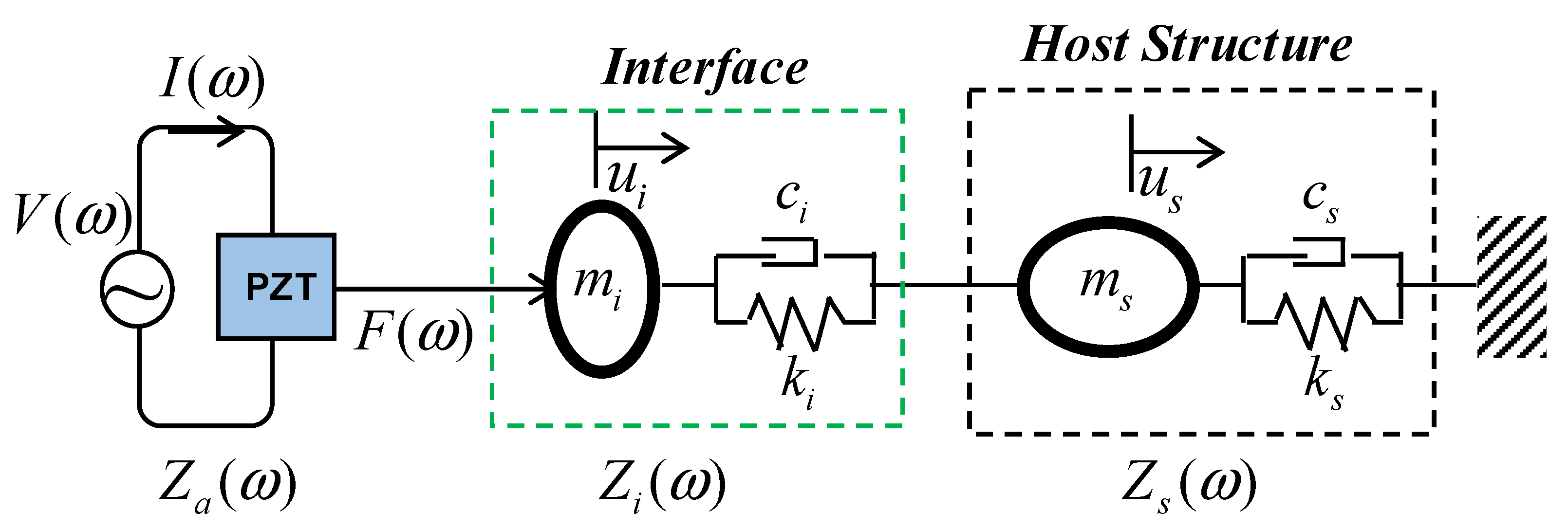
Figure 1 shows a simplified one-dimensional (1-D) impedance model that describes the coupling between the PZT patch and the host structure during the PZT’s excitation. The host structure is represented by dynamic parameters such as the mass (ms), the damping coefficient (cs), and the stiffness parameter (ks). When the harmonic voltage is applied, the PZT is deformed due to the inverse piezoelectric effect. Since the PZT is bonded to the host structure, this piezoelectric deformation induces a harmonic force F(ω) into the host structure. The ability of the host structure to resist this harmonic motion is defined as the mechanical impedance Zs(ω). For the 1-D impedance model shown in Figure 1, the mechanical impedance of the host structure is computed as the ratio of force F(ω) to velocity, as follows [36]:
Z s ( ω ) = F ( ω ) u ˙ s ( ω ) = c s + m s ω 2 k s / m s ω i
Where u ˙ s (ω) is the velocity of the host structure at the PZT’s driving point, ω is the angular frequency of the excitation voltage; i is the imaginary unit.
The measured electromechanical impedance, Z(ω), is a combined function of the structural impedance of the host structure (Zs(ω)) and the structural impedance of the PZT patch (Za(ω)), as follows [36]:
Z ( ω ) = V ( ω ) I ( ω ) = { i ω w a l a t a [ ε ^ 33 T 1 Z a ( ω ) / Z s ( ω ) + 1 d 3 x 2 Y ^ x x E ] } 1
where Y ^ x x E = ( 1 + i η ) Y x x E is the complex Young’s modulus of the PZT patch at zero electric field; ε ^ x x T = ( 1 i δ ) ε x x T is the complex dielectric constant at zero stress; the parameters η and δ are structural damping loss factor and dielectric loss factor of the PZT, respectively; d3x is the piezoelectric coupling constant in x-direction at zero stress; and w a , la, and ta are the width, length, and thickness of the PZT, respectively.
By substituting Equation (1) for Equation (2), the following expression is obtained:
Z ( ω ) = { i ω w a l a t a [ ε ^ 33 T 1 Z a ( ω ) / ( c s + m s ω 2 k s / m s ω i ) + 1 d 3 x 2 Y ^ x x E ] } 1
From Equation (3), it can be theoretically demonstrated that the measured electromechanical impedance at any swept frequency point consists of the information of the host structure (i.e., the mass, the damping, and the stiffness). Since the structural damage causes the change in those structural parameters, it is feasible to detect the structural damage by monitoring the alternation in the electromechanical impedance response.
It is noted that the electromechanical impedance response is a complex number, and the real part is often employed for damage detection since it contains more structural information than the imaginary part [13,14,37]. Meanwhile, the imaginary part mainly contains information about the PZT’s status, so it is often employed to diagnose the functionality of the PZT during structural health monitoring [37,38,39,40]. Furthermore, to effectively capture the initial stage of damage occurrence, the electromechanical impedance should be monitored in the resonant frequency band of the host structure [26].
To detect damage, the signature of post-damage impedance is often compared with the pre-damage impedance signature (i.e., the reference) by using statistical damage metrics. The root-mean-square deviation (RMSD) is one of the most widely used damage metrics in impedance-based damage detection. The RMSD index is calculated by [41,42]:
R M S D ( Z , Z * ) = j = 1 N [ Z * ( ω j ) Z ( ω j ) ] 2 / j = 1 N [ Z ( ω j ) ] 2
in which Z(ωj) is the impedance signature measured for the jth frequency at the reference state and Z*(ωj) is the impedance signature at the unknown stage (e.g., damaged stage), and N denotes the number of swept frequency points. Ideally, the RMSD index is equal to 0 if the two impedance signatures are identical, and therefore the structure is undamaged. The RMSD index is over 0 in the case of damage occurrence.

3. Design of Single-Point Mount PZT Interface and Its Numerical Feasibility

3.1. Conceptual Design of Single-Point Mount PZT Interface and Its Electromechanical Impedance

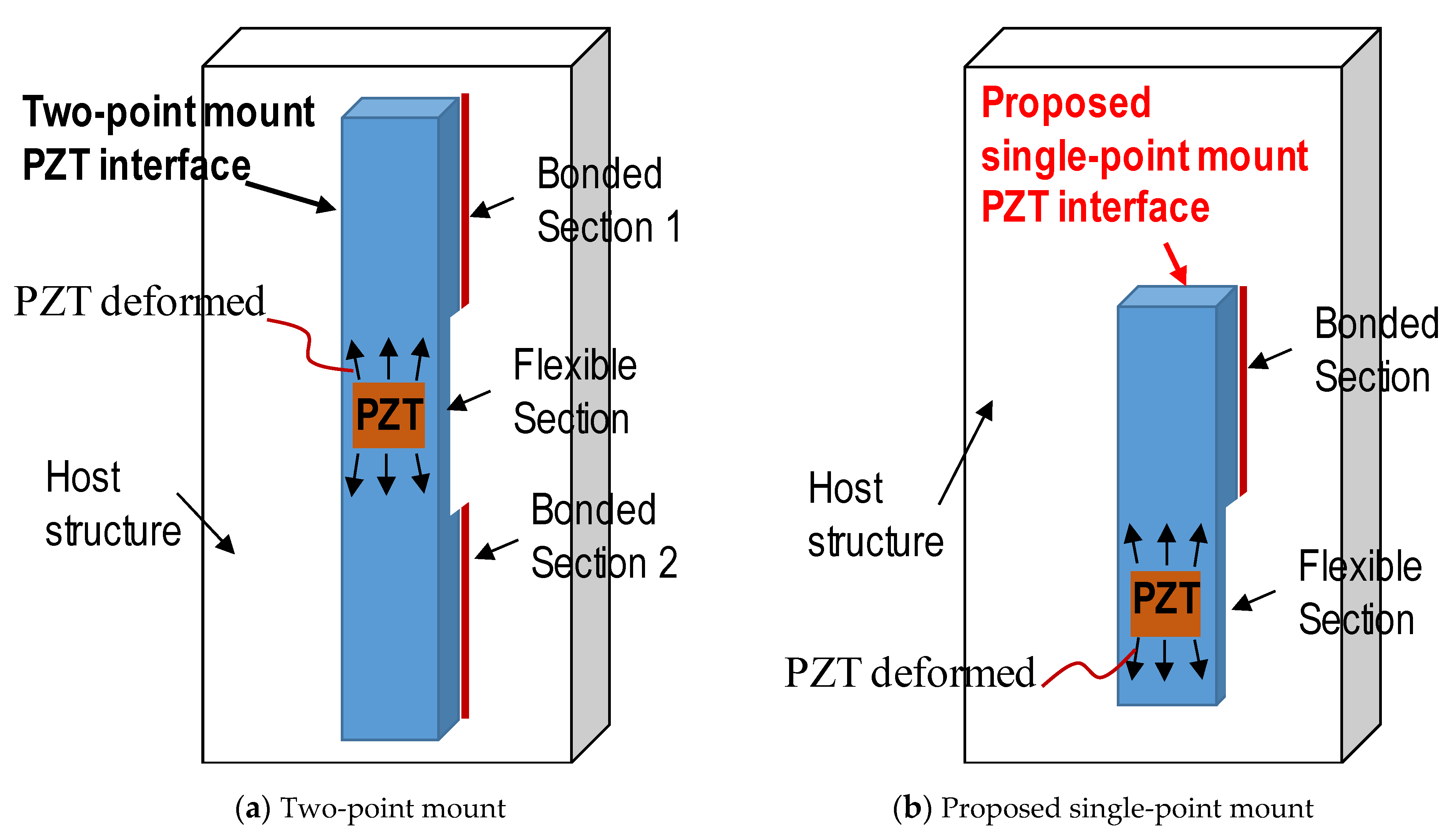
Figure 2a illustrates the conceptual design of the two-point mount PZT interface, which was previously developed in [27,28,43]. This design consists of three segments: two outside bonded parts and a middle unbonded part. The two outside parts allow the device to be easily mounted on and removed from the host structure, and the middle part is equipped with a PZT and designed as a flexural section to create strong vibrational responses during the PZT’s excitation. By controlling the geometrical and structural parameters of the flexural part, we can create strong impedance signals in any predefined frequency band. However, using two bonded sections could cause inconveniences during installation and replacement processes because it is hard to ensure the same bonding layers in the field. In addition, during its operation under varying ambient temperatures, additional stresses can be easily induced in the interface body due to the constraints of the two bonded sections [34]. This could cause bond degradation and significant changes in the resonant peaks.
To overcome this drawback, we created a novel design of the mountable PZT interface that uses a single-point mount, as conceptually sketched in Figure 2b. In this new design, the flexible section of the previous interface is kept to create strong resonances and one bonded section is eliminated. With only one bonded section, the PZT interface can be more conveniently installed on the existing structure or more easily replaced when it is degraded. Furthermore, the risk of bond degradation can be also reduced due to fewer bonding layers and free thermal expansion of the flexible part under variation in ambient temperature.
The interaction of the PZT interface and the host structure during the PZT’s excitation can be described by the 2-degree-of-freedom (dof) model [34], as sketched in Figure 3. The dynamic properties of the interface body include the mass (mi), the damping coefficient (ci), and the stiffness parameter (ki). In Figure 3, ui is the displacement of the interface at the PZT’s driving point, Zi(ω) is the mechanical impedance of the interface. During the PZT’s excitation, there are coupling responses between the PZT and the interface and between the interface and the host structure. By using the 2-dof model, the equivalent mechanical impedance of the interface–host structure system Z ¯ ( ω ) can be expressed by [34]:
Z ¯ ( ω ) = K 11 ( ω ) K 22 ( ω ) K 12 2 ( ω ) i ω K 22 ( ω )
where the terms (Kmn(ω)), in which m, n = 1, 2, are the “dynamic stiffness” terms and are expressed by:
[ K 11 ( ω ) K 12 ( ω ) K 12 ( ω ) K 22 ( ω ) ] = [ ω 2 m i + i ω c i + k i i ω c i k i i ω c i k i ω 2 m s + i ω ( c i + c s ) + ( k i + k s ) ]
By replacing Zs in Equation (2) with Z ¯ ( ω ) in Equation (5), we can obtain the overall electromechanical impedance of the PZT interface–host structure system as follows:
Z ( ω ) = { i ω w a l a t a [ ε ^ 33 T 1 Z a ( ω ) / ( K 11 ( ω ) K 22 ( ω ) K 12 2 ( ω ) i ω K 22 ( ω ) ) + 1 d 3 x 2 Y ^ x x E ] } 1
Equation (7) shows that if the structural parameters of the host structure are altered due to the structural damage, the electromechanical impedance measured from the PZT interface at any frequency points change. Therefore, it is feasible to detect the structural damage by tracking the change in the impedance signature of the PZT interface.

3.2. Numerical Feasibility of Single-Point Mount PZT Interface

The numerical impedance simulations were conducted to verify the feasibility of the proposed PZT interface prototype for detecting stress change in a beam-like structure. We used a commercial finite element program, COMSOL Multiphysics, to perform the simulations. Figure 4 shows the geometry and the clamped–clamped boundary conditions of the beam. The beam had a uniform cross-section of 50 × 5 mm and a length of 300 mm. To simulate the effect of the prestress on the impedance response, a concentrated load was placed on the middle of the beam. Three levels of the concentrated load P = 0, 1, and 2 kN were investigated sequentially. A finite element model of the beam equipped with a single-point PZT interface was constructed in COMSOL, as shown in Figure 5a. In the finite element model, the PZT interface was installed in the middle of the beam. It was designed with a bonded section of 35 × 33 × 5 mm, a flexible section of 30 × 33 × 4 mm, and a PZT of 20 × 20 × 0.51 mm. The interface bodies and the beam were assigned by aluminum with the mechanical properties listed in Table 1 [35]. The PZT patches were added by the piezoelectric material PZT-5A, with the properties listed in Table 2 [35]. To acquire the impedance responses, a harmonic excitation voltage with an amplitude of 1 V was simulated on the top surface of the PZT patch, and the ground electrode was applied to the bottom surface.
Figure 5b shows the finite element model meshed by hexahedral solid elements (8-nodes). The finer meshing was used for the PZT to accurately simulate the stress wave. Two modules of COMSOL, piezoelectric devices and solid mechanics, were coupled to simulate the electromechanical impedance response of the PZT interfaces. Figure 5c shows the deformation of the PZT interface–beam system under a piezoelectric excitation at 10 kHz. It is shown that the interface was strongly coupled with the beam during the excitation, as explained in the previous section. When the beam was stressed or damaged, this coupled vibration response was altered, making the variation of the electromechanical impedance at that frequency.
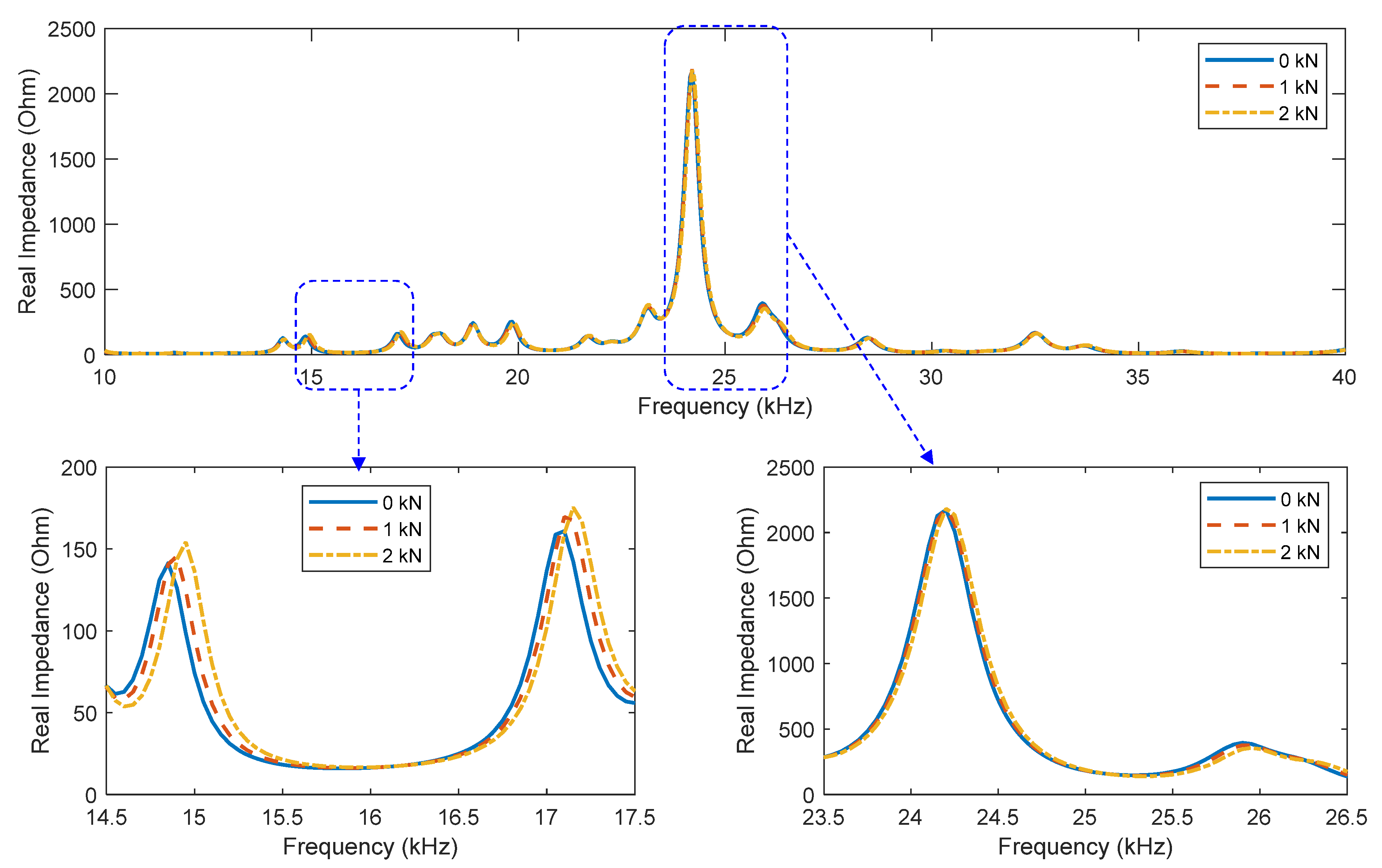
The real part of the electromechanical impedance in the frequency band of 10–40 kHz is plotted in Figure 6. Many resonant peaks were observed in the examined frequency band, showing strong coupling responses between the PZT interface and the host beam. The figure shows that the impedance signature was sensitively altered by the increment of the applied load. Specifically, the impedance peaks shifted towards the right, implying the enhancement of the modal stiffness of the beam. This is reasonable because the examined beam was thin and therefore it gained tensile stiffness under the effect of the concentrated load.
The RMSD indices of the impedance signatures were computed using the frequency band of 10–40 kHz and are plotted in Figure 7. The result shows that the RMSD index increased with the applied load quite linearly. By using the RMSD index, it was feasible to detect the stress change in the beam. The numerical simulation verified the feasibility of the proposed single-point mount PZT interface for impedance-based stress monitoring.

4. Experimental Feasibility Study

4.1. Experimental Setup

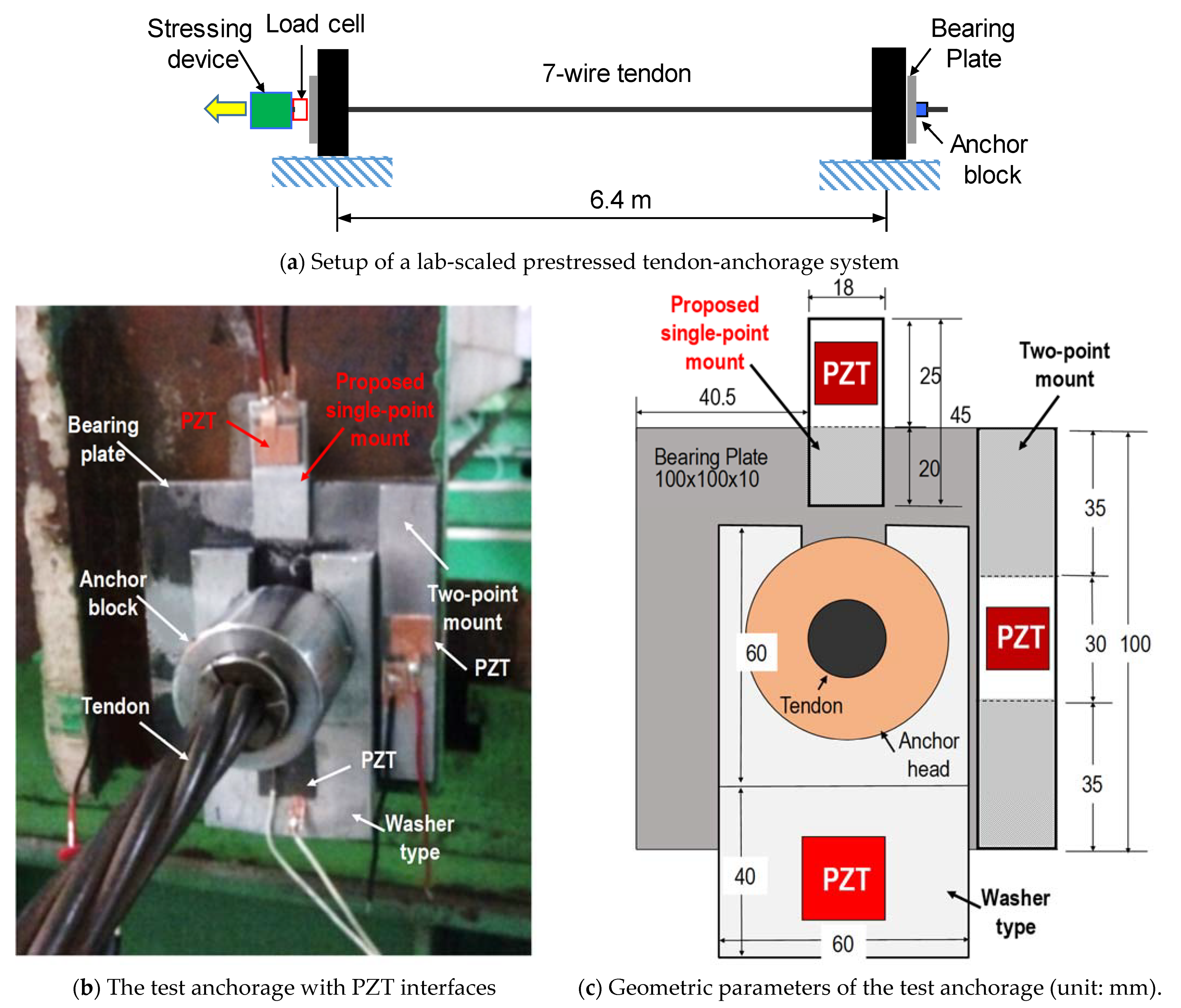
An experiment was carried out for a lab-scale cable-anchorage system to validate the implementation of the proposed PZT interface for impedance-based anchor force monitoring. As shown in Figure 8a, a steel tendon with a length of 6.4 m was anchored by two bearing plates at two ends. A stressing device was instrumented at the left end to control the prestress force. The stressing device included a double acting cylinder hydraulic jack (Shinjin Hydrotec, model: DRW-50150, capacity 50 ton) and a pump (model: DP-2A, capacity 700 kg/cm2). A load cell was also installed at the left anchorage to measure the tendon force. The experimental setup of the right anchorage is depicted in Figure 8b. The anchorage was equipped with three PZT interfaces (i.e., the washer type, the two-point mount, and the proposed single-point mount models). The interface bodies were fabricated from aluminum and the transducers were prepared using PZT-5A. The geometric parameters of the PZT interfaces and their locations on the bearing plate are sketched in Figure 8c. The PZT on the washer-type model had a size of 20 × 20 × 0.51 mm and the others had the same size of 15 × 15 × 0.51 mm.
To obtain the electromechanical impedance, the PZT patches were excited by a harmonic voltage of 1V amplitude, and the impedance responses were measured by a commercial impedance analyzer, HIOKI 3532. The anchorage was initially prestressed by the stressing device to the level of 5 ton (T1), and this prestress level was considered the healthy state. Next, the prestress force was sequentially reduced to 4 ton (T2), 3 ton (T3), and 2 ton (T4) to simulate the prestress-loss cases. For each level of prestress force, five impedance signals in the frequency range of 10–100 kHz (501 swept points) were sampled. For the impedance measurement analyzer HIOKI-3532, we selected sampling rates as “FAST” with the most rapid measurement time of 5 ms (sampling rate of 200 Hz). The laboratory temperature was controlled within 23–24 °C during the experiment to avoid the temperature effect on the measured electromechanical impedance of the PZT interfaces.

4.2. Electromechanical Impedance Responses

The real part of the electromechanical impedance of the three transducer models is plotted in Figure 9a. Many resonant peaks with different frequencies were observed in the examined frequency band (see Figure 9a). The impedance signature of the washer-type model showed two strong peaks around 17 kHz and 60 kHz, whereas the two-point mount model showed two significant peaks around 18 kHz and 81 kHz [28]. The proposed single-point mount model produced a few impedance peaks with considerable magnitudes in the band of 10–100 kHz (see Figure 9a). They were identified around 26 kHz, 30 kHz, 35 kHz, 74 kHz, and 93 kHz.
Figure 9b shows the imaginary part of the electromechanical impedance of the three transducer models. It is shown that the curves of the imaginary part of the two-point mount model and the proposed single-point mount model were quite consistent, whereas the curve of the washer-type model showed a downward deviation. The first and the second models used the same size of PZT, whereas the third model used a larger size of the PZT. The larger size of the PZT caused the lower curve of the imaginary part of the electromechanical impedance, as experimentally demonstrated in [38].

4.3. Monitoring of Anchor Force Reduction Using Electromechanical Impedance Responses

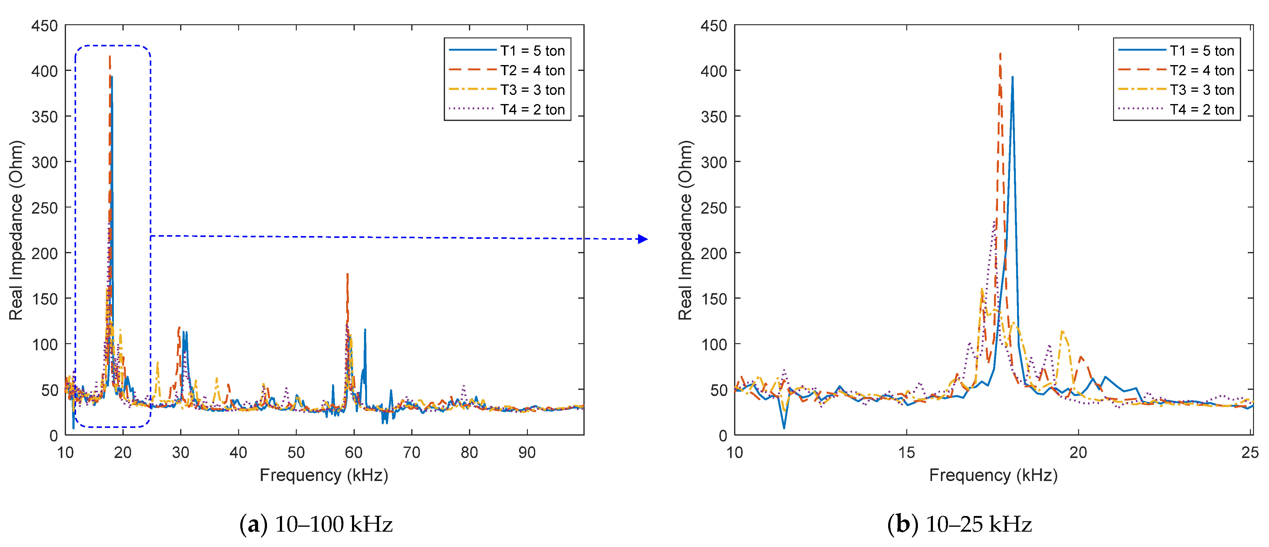
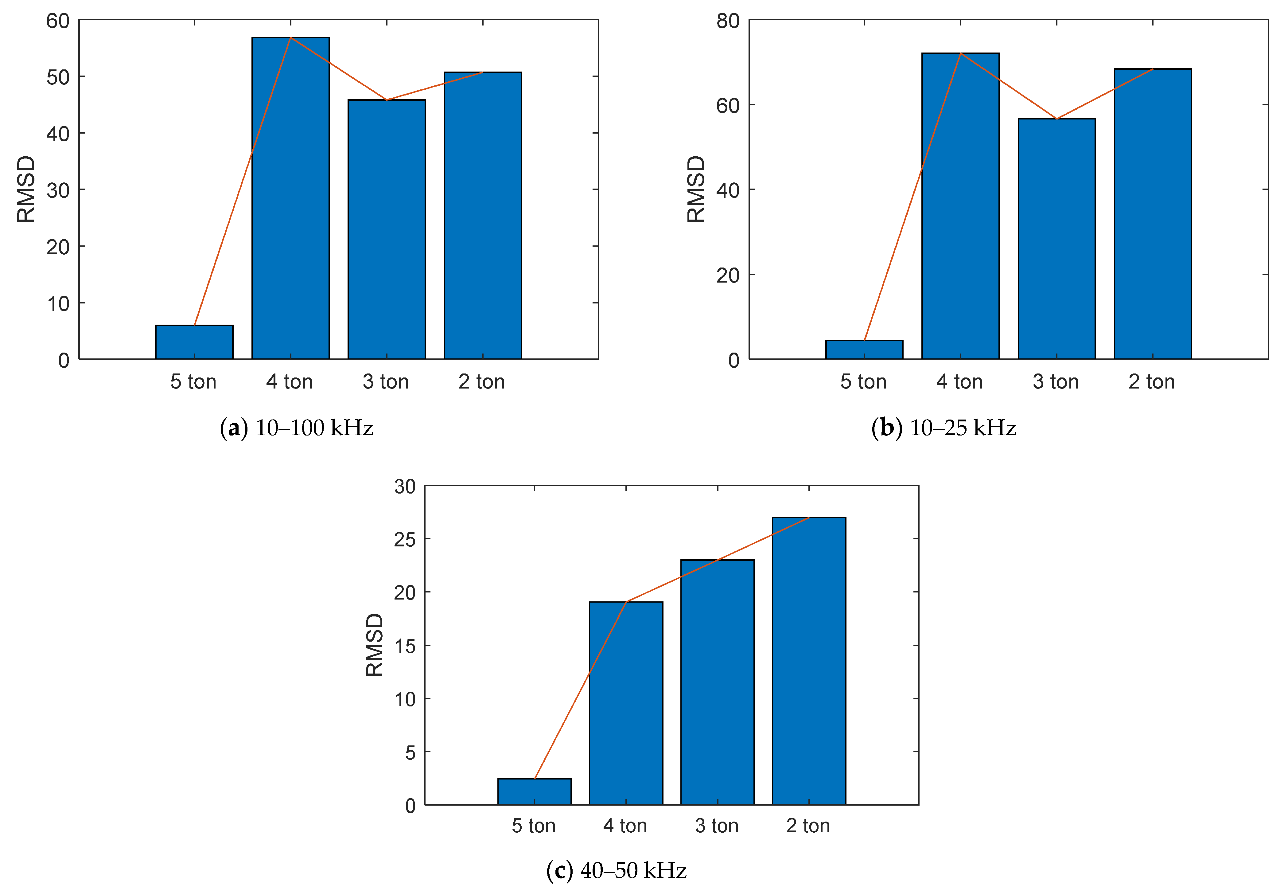
Figure 10a shows the real impedance responses in 10–100 kHz of the washer-type PZT interface under different prestress levels. As zoomed in on in Figure 10b, the real impedance in 10–25 kHz was sensitively varied with the reduction of the prestress force. Particularly, the impedance peaks were shifted to the left as the prestress force was decreased. To detect the change in the prestress force, the RMSD index of the real impedance was computed using the whole frequency range of 10–100 kHz, as plotted in Figure 11a. It is shown that the RMSD was altered when the prestress force was reduced; however, the relationship between them was considerably nonlinear. The real impedance in a subrange of 10–25 kHz, which contained the most significant peaks, was examined. As shown in Figure 11b, the RMSD of the subrange 10–25 kHz also showed a high level of nonlinearity with the prestress force. There was a sharp drop in the RMSD at the prestress force T3 = 3 ton. This means that the reduction of the prestress force from T4 = 4 ton to T3 = 3 ton was not successfully detected. We analyzed different subranges within 10–100 kHz, and found that the result was improved when the frequency band of 40–50 kHz was employed. As shown in Figure 11c, there was no drop in the RMSD index and three prestress-loss cases could be classified. However, the relationship between the RMSD and the prestress force was pretty nonlinear.
Next, the impedance response of the two-point mount PZT interface was analyzed. Figure 12a shows the real impedance signatures in 10–100 kHz under different prestress forces. The real impedance was altered as the prestress force went down, as seen in Figure 12b. The impedance peaks tended to shift to the left side. The RMSD indices were computed for the whole frequency band of 10–100 kHz and the narrow band of 78–85 kHz (which contained the second significant peak), as shown in Figure 13a,b, respectively. The figures show that the relationships between the RMSD and the prestress force were pretty linear.
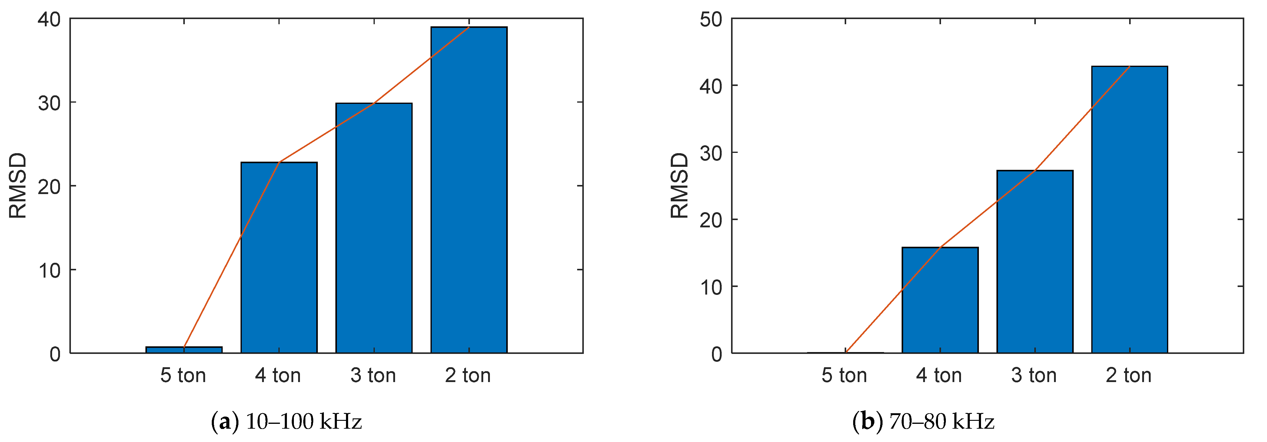
Lastly, the impedance response of the proposed single-point mount model was analyzed. The real impedance signatures in 10–100 kHz for different prestress forces were shown in Figure 14a. The real impedance of the resonant peaks was sensitively changed with the decreased prestress force, as seen in Figure 14b. Similar to the above models, the impedance peaks were shifted leftward. The RMSD was computed for the whole frequency band of 10–100 kHz and plotted in Figure 15a. It is shown that all prestress-loss cases were well classified using the RMSD index and the relationship between the RMSD and the prestress force was found to be pretty linear. This is similar to the previous observation by finite element modeling in Section 3.2. However, we found that when the narrow band of 70–80 kHz (which contained the second significant peak) was employed, the result was much enhanced. In particular, the RMSD of the impedance signatures of 70–80 kHz showed a strong linear relationship with the prestress force, as seen in Figure 15b.
In our method, the proposed PZT interface was mounted on the bearing plate. In general, any changes in the structural parameters of the bearing plate lead to variations in the electromechanical impedance of the PZT interface, as previously explained in Section 3.1. In the experiment, because the bearing plate was clamped by the anchor block, the electromechanical impedance was varied with the prestress force. If the bearing plate is cracked, its structural parameters change, and this also leads to variations in the electromechanical impedance of the PZT interface. In reality, the electromechanical impedance of the PZT interface is also influenced by the variation in environmental temperatures. The impedance is shifted even when there is no structural damage [34,44]. Therefore, to secure the reliability of the damage detection results, temperature-compensated algorithms are often adopted to filter the effects of temperature change from the electromechanical impedance [15,22,43,45]. This remains to be studied in the future.

5. Summary and Conclusions

In this study, we newly proposed a single-point mount PZT interface for the anchor force monitoring problem. The proposed device uses a single-point mount technique to overcome the limitation of the previous two-point mount model. The electromechanical impedance response of the proposed device was theoretically explained by using a 2-dof impedance model of the PZT interface–host structure system. The proof-of-concept of the proposed PZT interface for impedance monitoring was demonstrated by finite element modeling. To demonstrate the practical application feasibility of the proposed method, a lab-scaled experiment was carried out on an anchor system. Three PZT interface models were designed and installed at the anchorage, including the proposed model, the two-point mount model, and the washer-type model. The electromechanical impedance responses of the models were analyzed and the RMSD was calculated for the prestress force monitoring.
From the finite element and experimental analyses, it is concluded that (1) the proposed single-point mount PZT interface can produce strong resonant impedance responses that are sensitive to the prestress force changes, (2) the RMSD index indicates that the proposed single-point mount model is concretely linear with the prestress-loss when a proper frequency band is used (e.g., the frequency band of 70–80 kHz in the experimentation), (3) the performance of the proposed model for the prestress force monitoring is at least comparable with the previous models (i.e., the washer-type mount and the two-point mount), and (4) the proposed PZT interface prototype is simple and convenient for on-site installation or replacement and therefore promising for future development of impedance-based anchor force monitoring systems.
This is a preliminary study to show the feasibility of the proposed single-point mount PZT interface, and remaining work includes (1) analyzing the geometric effect of the proposed device and optimizing its dimensional parameters, (2) analyzing the local dynamics characteristics of the proposed PZT interface, and (3) evaluating the performance of the device under varying ambient conditions such as temperature change.

Author Contributions

Conceptualization, T.-C.H., D.-D.H. and T.-C.L.; methodology, T.-C.H. and D.-D.H.; validation, T.-C.H., D.-D.H. and T.-C.L.; formal analysis, T.-C.H. and D.-D.H.; writing—original draft preparation, T.-C.H., D.-D.H. and T.-C.L.; writing—review and editing, T.-C.H. All authors have read and agreed to the published version of the manuscript.

Funding

This research received no external funding.

Data Availability Statement

The data are available upon request.

Acknowledgments

We acknowledge the support of time and facilities from Ho Chi Minh City University of Technology (HCMUT), VNU-HCM, for this study.

Conflicts of Interest

The authors declare no conflict of interest.

References

  1. Chandrasekar, P.; Dayaratnam, P. Analysis of probability of failure of prestressed concrete beams. Build. Sci. 1975, 10, 161–167. [Google Scholar] [CrossRef]
  2. Yuyama, S.; Yokoyama, K.; Niitani, K.; Ohtsu, M.; Uomoto, T. Detection and evaluation of failures in high-strength tendon of prestressed concrete bridges by acoustic emission. Constr. Build. Mater. 2007, 21, 491–500. [Google Scholar] [CrossRef]
  3. Onyemelukwe, O.; Kunnath, S. Field Measurement and Evaluation of Time-Dependent Losses in Prestressed Concrete Bridges; Final Report, Project Number: WPI-0510735; Florida Department of Transportation: Tallahassee, FL, USA, 1997. [Google Scholar]
  4. Guo, T.; Chen, Z.; Lu, S.; Yao, R. Monitoring and analysis of long-term prestress losses in post-tensioned concrete beams. Measurement 2018, 122, 573–581. [Google Scholar] [CrossRef]
  5. Meissner, J.; Nowak, W.; Slowik, V.; Klink, T. Strain Monitoring at a Prestressed Concrete Bridge. In Proceedings of the 12th International Conference on Optical Fiber Sensors, Williamsburg, VA, USA, 28 October 1997. [Google Scholar]
  6. Nellen, P.; Broennimann, R.; Frank, A.; Mauron, P.; Sennhauser, U. Structurally Embedded Fiber Bragg Gratings: Civil Engineering Applications; SPIE: Boston, MA, USA, 1999; Volume 3860. [Google Scholar]
  7. Suhartomo, A.; Simatupang, J.W.; Widjaja, B.; Gapsari, F. Feasibility Study on Structural Health Monitoring Systems Using Fiber-Optic Sensors (FOS) Technology for Transportation Infrastructures in Indonesia. IOP Conf. Ser. Mater. Sci. Eng. 2019, 494, 012054. [Google Scholar] [CrossRef]
  8. Kim, S.T.; Park, Y.; Park, S.Y.; Cho, K.; Cho, J.R. A sensor-type PC strand with an embedded FBG sensor for monitoring prestress forces. Sensors 2015, 15, 1060–1070. [Google Scholar] [CrossRef] [Green Version]
  9. Huynh, T.-C.; Kim, J.-T. FOS-Based Prestress Force Monitoring and Temperature Effect Estimation in Unbonded Tendons of PSC Girders. J. Aerosp. Eng. 2017, 30, B4016005. [Google Scholar] [CrossRef]
  10. Kim, Y.-S.; Sung, H.-J.; Kim, H.; Kim, J.-M. Monitoring of tension force and load transfer of groundanchor by using optical FBG sensors embedded tendon. Smart Struct. Syst. 2011, 7, 303–317. [Google Scholar] [CrossRef]
  11. Ai, D.; Zhu, H.; Luo, H.; Yang, J. An effective electromechanical impedance technique for steel structural health monitoring. Constr. Build. Mater. 2014, 73, 97–104. [Google Scholar] [CrossRef]
  12. Bhalla, S.; Soh, C.K. Electro-Mechanical Impedance Technique. In Smart Materials in Structural Health Monitoring, Control and Biomechanics; Soh, C.-K., Yang, Y., Bhalla, S., Eds.; Springer: Berlin/Heidelberg, Germany, 2012; pp. 17–51. [Google Scholar] [CrossRef]
  13. Park, G.; Sohn, H.; Farrar, C.R.; Inman, D.J. Overview of piezoelectric impedance-based health monitoring and path forward. Shock Vib. Dig. 2003, 35, 451–464. [Google Scholar] [CrossRef] [Green Version]
  14. Min, J.; Park, S.; Yun, C.-B. Impedance-based structural health monitoring using neural networks for autonomous frequency range selection. Smart Mater. Struct. 2010, 19, 125011. [Google Scholar] [CrossRef]
  15. Lim, H.J.; Kim, M.K.; Sohn, H.; Park, C.Y. Impedance based damage detection under varying temperature and loading conditions. NDT E Int. 2011, 44, 740–750. [Google Scholar] [CrossRef]
  16. Ho, D.D.; Lee, P.Y.; Nguyen, K.D.; Hong, D.S.; Kim, J.T.; Shin, S.W.; Yun, C.B.; Shinozuka, M. Solar-powered multi-scale sensor node on Imote2 platform for hybrid SHM in cable-stayed bridge. Smart Struct. Syst. 2012, 9, 145–164. [Google Scholar] [CrossRef]
  17. Campeiro, L.M.; da Silveira, R.Z.; Baptista, F.G. Impedance-based damage detection under noise and vibration effects. Struct. Health Monit. 2018, 17, 654–667. [Google Scholar] [CrossRef]
  18. Singh, S.K.; Soman, R.; Wandowski, T.; Malinowski, P. A Variable Data Fusion Approach for Electromechanical Impedance-Based Damage Detection. Sensors 2020, 20, 4204. [Google Scholar] [CrossRef]
  19. Chen, Y.; Xue, X. Advances in the Structural Health Monitoring of Bridges Using Piezoelectric Transducers. Sensors 2018, 18, 4312. [Google Scholar] [CrossRef] [Green Version]
  20. Kim, J.-T.; Park, J.-H.; Hong, D.-S.; Park, W.-S. Hybrid health monitoring of prestressed concrete girder bridges by sequential vibration-impedance approaches. Eng. Struct. 2010, 32, 115–128. [Google Scholar] [CrossRef]
  21. Abdel-Jaber, H.; Glisic, B. Monitoring of prestressing forces in prestressed concrete structures—An overview. Struct. Control Health Monit. 2019, 26, e2374. [Google Scholar] [CrossRef] [Green Version]
  22. Huynh, T.C.; Kim, J.T. RBFN-based temperature compensation method for impedance monitoring in prestressed tendon anchorage. Struct. Control Health Monit. 2018, 25, e2173. [Google Scholar] [CrossRef]
  23. Kim, J.-T.; Park, J.-H.; Hong, D.-S.; Cho, H.-M.; Na, W.-B.; Yi, J.-H. Vibration and impedance monitoring for prestress-loss prediction in PSC girder bridges. Smart Struct. Syst. 2009, 5, 81–94. [Google Scholar] [CrossRef]
  24. Huynh, T.-C.; Lee, S.-Y.; Dang, N.-L.; Kim, J.-T. Sensing region characteristics of smart piezoelectric interface for damage monitoring in plate-like structures. Sensors 2019, 19, 1377. [Google Scholar] [CrossRef] [Green Version]
  25. Huynh, T.-C.; Dang, N.-L.; Kim, J.-T. Advances and challenges in impedance-based structural health monitoring. Struct. Monit. Maint. 2017, 4, 301–329. [Google Scholar] [CrossRef]
  26. Nguyen, K.-D.; Kim, J.-T. Smart PZT-interface for wireless impedance-based prestress-loss monitoring in tendon-anchorage connection. Smart Struct. Syst. 2012, 9, 489–504. [Google Scholar] [CrossRef]
  27. Huynh, T.-C.; Kim, J.-T. Impedance-Based Cable Force Monitoring in Tendon-Anchorage Using Portable PZT-Interface Technique. Math. Probl. Eng. 2014, 2014, 11. [Google Scholar] [CrossRef]
  28. Huynh, T.-C.; Park, Y.-H.; Park, J.-H.; Kim, J.-T. Feasibility verification of mountable PZT-interface for impedance monitoring in tendon-anchorage. Shock Vib. 2015, 2015, 262975. [Google Scholar] [CrossRef] [Green Version]
  29. Ryu, J.-Y.; Huynh, T.-C.; Kim, J.-T. Tension force estimation in axially loaded members using wearable piezoelectric interface technique. Sensors 2019, 19, 47. [Google Scholar] [CrossRef] [Green Version]
  30. Tawie, R.; Park, H.B.; Baek, J.; Na, W.S. Damage Detection Performance of the Electromechanical Impedance (EMI) Technique with Various Attachment Methods on Glass Fibre Composite Plates. Sensors 2019, 19, 1000. [Google Scholar] [CrossRef] [Green Version]
  31. Huynh, T.-C.; Kim, J.-T. Quantitative damage identification in tendon anchorage via PZT interface-based impedance monitoring technique. Smart Struct. Syst. 2017, 20, 181–195. [Google Scholar]
  32. Dang, N.L.; Huynh, T.C.; Pham, Q.Q.; Lee, S.Y.; Kim, J.T. Damage-sensitive impedance sensor placement on multi-strand anchorage based on local stress variation analysis. Struct. Control Health Monit. 2020, 27, e2547. [Google Scholar] [CrossRef]
  33. Dang, N.-L.; Huynh, T.-C.; Kim, J.-T. Local strand-breakage detection in multi-strand anchorage system using an impedance-based stress monitoring method—Feasibility study. Sensors 2019, 19, 1054. [Google Scholar] [CrossRef] [Green Version]
  34. Huynh, T.-C.; Kim, J.-T. Quantification of temperature effect on impedance monitoring via PZT interface for prestressed tendon anchorage. Smart Mater. Struct. 2017, 26, 125004. [Google Scholar] [CrossRef]
  35. Huynh, T.-C.; Lee, K.-S.; Kim, J.-T. Local dynamic characteristics of PZT impedance interface on tendon anchorage under prestress force variation. Smart Struct. Syst. 2015, 15, 375–393. [Google Scholar] [CrossRef]
  36. Liang, C.; Sun, F.P.; Rogers, C.A. Coupled Electro-Mechanical Analysis of Adaptive Material Systems—Determination of the Actuator Power Consumption and System Energy Transfer. J. Intell. Mater. Syst. Struct. 1994, 5, 12–20. [Google Scholar] [CrossRef]
  37. Park, G.; Farrar, C.R.; di Scalea, F.L.; Coccia, S. Performance assessment and validation of piezoelectric active-sensors in structural health monitoring. Smart Mater. Struct. 2006, 15, 1673. [Google Scholar] [CrossRef]
  38. Nguyen, B.-P.; Tran, Q.H.; Nguyen, T.-T.; Pradhan, A.M.S.; Huynh, T.-C. Understanding Impedance Response Characteristics of a Piezoelectric-Based Smart Interface Subjected to Functional Degradations. Complexity 2021, 2021, 5728679. [Google Scholar] [CrossRef]
  39. Park, G.; Farrar, C.R.; Rutherford, A.C.; Robertson, A.N. Piezoelectric Active Sensor Self-Diagnostics Using Electrical Admittance Measurements. J. Vib. Acoust. 2006, 128, 469–476. [Google Scholar] [CrossRef]
  40. Park, S.; Park, G.; Yun, C.-B.; Farrar, C.R. Sensor Self-diagnosis Using a Modified Impedance Model for Active Sensing-based Structural Health Monitoring. Struct. Health Monit. 2009, 8, 71–82. [Google Scholar] [CrossRef]
  41. Sun, F.P.; Chaudhry, Z.; Liang, C.; Rogers, C.A. Truss Structure Integrity Identification Using PZT Sensor-Actuator. J. Intell. Mater. Syst. Struct. 1995, 6, 134–139. [Google Scholar] [CrossRef]
  42. Saravanan, T.J.; Balamonica, K.; Priya, C.B.; Gopalakrishnan, N.; Murthy, S.G.N. Piezoelectric EMI–Based Monitoring of Early Strength Gain in Concrete and Damage Detection in Structural Components. J. Infrastruct. Syst. 2017, 23, 04017029. [Google Scholar] [CrossRef]
  43. Nguyen, T.T.; Kim, J.T.; Ta, Q.B.; Ho, D.D.; Phan, T.T.V.; Huynh, T.C. Deep learning-based functional assessment of piezoelectric-based smart interface under various degradations. Smart Struct. Syst. 2021, 28, 69–87. [Google Scholar]
  44. Li, X.; Qu, W.; Xiao, L.; Lu, Y. Removal of temperature effect in impedance-based damage detection using the cointegration method. J. Intell. Mater. Syst. Struct. 2019, 30, 2189–2197. [Google Scholar] [CrossRef]
  45. Krishnamurthy, K.; Lalande, F.; Rogers, C.A. Effects of temperature on the electrical impedance of piezoelectric sensors. In Proceedings of the SPIE Smart Structures and Materials 1996: Smart Structures and Integrated Systems, San Diego, CA, USA, 25 February 1996. [Google Scholar]
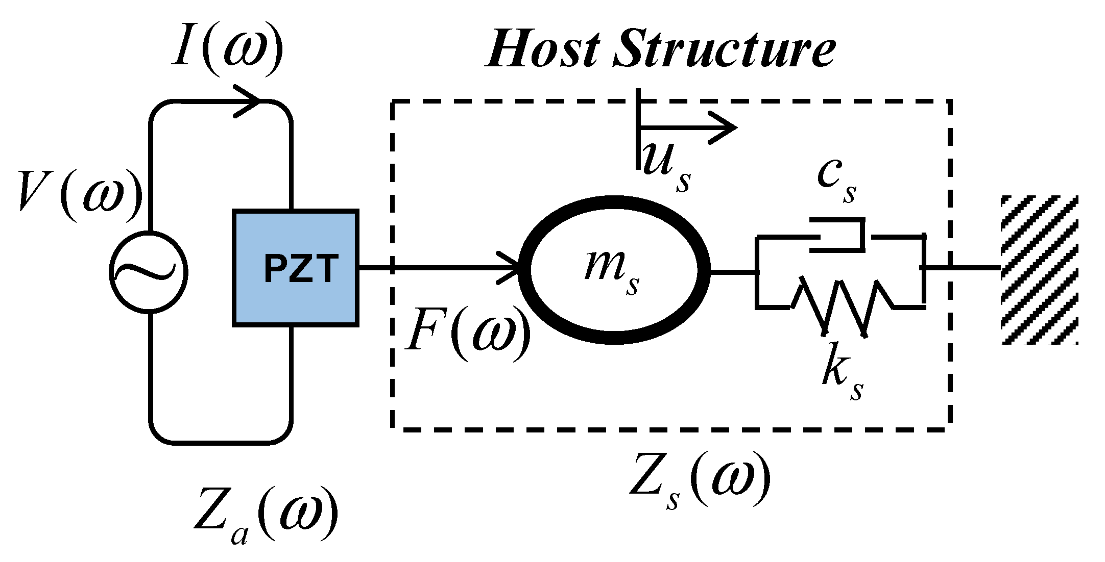
Figure 1. The one-dimensional model of PZT–host structure interaction (us is the displacement, I(ω) is the output current, V(ω) is the applied voltage).
Buildings 11 00382 g001
Figure 2. Conceptual design of the mountable PZT interface: two-point mount vs. single-point mount.
Buildings 11 00382 g002
Figure 3. The 2-dof electromechanical impedance model of the PZT interface–host structure system.
Buildings 11 00382 g003
Figure 4. Geometrical parameters and boundary conditions of the host beam (unit: mm).
Buildings 11 00382 g004
Figure 5. The finite element model of the beam equipped with a single-point mount PZT interface.
Buildings 11 00382 g005aBuildings 11 00382 g005b
Figure 6. Impedance responses of two PZT interfaces under an ascending concentrated load.
Buildings 11 00382 g006
Figure 7. The RMSD index of the impedance signatures under an ascending concentrated load.
Buildings 11 00382 g007
Figure 8. Setup of the lab-scaled prestressed anchorage.
Buildings 11 00382 g008
Figure 9. Measured electromechanical impedance responses of three PZT interface models.
Buildings 11 00382 g009
Figure 10. Real electromechanical impedance responses of the washer-type PZT interface.
Buildings 11 00382 g010
Figure 11. The RMSD index of the electromechanical impedance of the washer-type PZT interface.
Buildings 11 00382 g011
Figure 12. Real electromechanical impedance responses of the two-point mount PZT interface.
Buildings 11 00382 g012
Figure 13. The RMSD index of the electromechanical impedance of the two-point mount PZT interface.
Buildings 11 00382 g013
Figure 14. Real electromechanical impedance responses of the single-point mount PZT interface.
Buildings 11 00382 g014
Figure 15. The RMSD index of the electromechanical impedance of the single-point mount PZT interface.
Buildings 11 00382 g015
Table 1. Mechanical properties of the aluminum [35].
ParametersThe Interface and the Beam
Young’s modulus, E (GPa)70
Poisson’s ratio, υ0.33
Mass density, ρ (kg/m3)2700
Damping loss factor, η0.02
Table 2. Properties of the PZT-5A patch [35].
ParametersValue
Elastic compliance, s i j k l E (m2/N) ( 16.4 5.74 7.22 0 0 0 5.74 16.4 7.22 0 0 0 7.22 7.22 18.8 0 0 0 0 0 0 47.5 0 0 0 0 0 0 47.5 0 0 0 0 0 0 44.3 ) × 10 12
Dielectric coupling constant, d k i j (C/N) ( 0 0 171 0 0 171 0 0 374 0 584 0 584 0 0 0 0 0 ) × 10 12
Permittivity, ε j k T (Farad/m) ( 1730 0 0 0 1730 0 0 0 1700 ) × ( 8.854 × 10 12 )
Mass density, ρ (kg/m3)7750
Damping loss factor, η0.005
Dielectric loss factor, δ0.015
Publisher’s Note: MDPI stays neutral with regard to jurisdictional claims in published maps and institutional affiliations.