
Seismic Strengthening of RC Structures Using Wall-Type Kagome Damping System


Abstract
:1. Introduction

2. Kagome Damper and Wall-Type Kagome Damping System
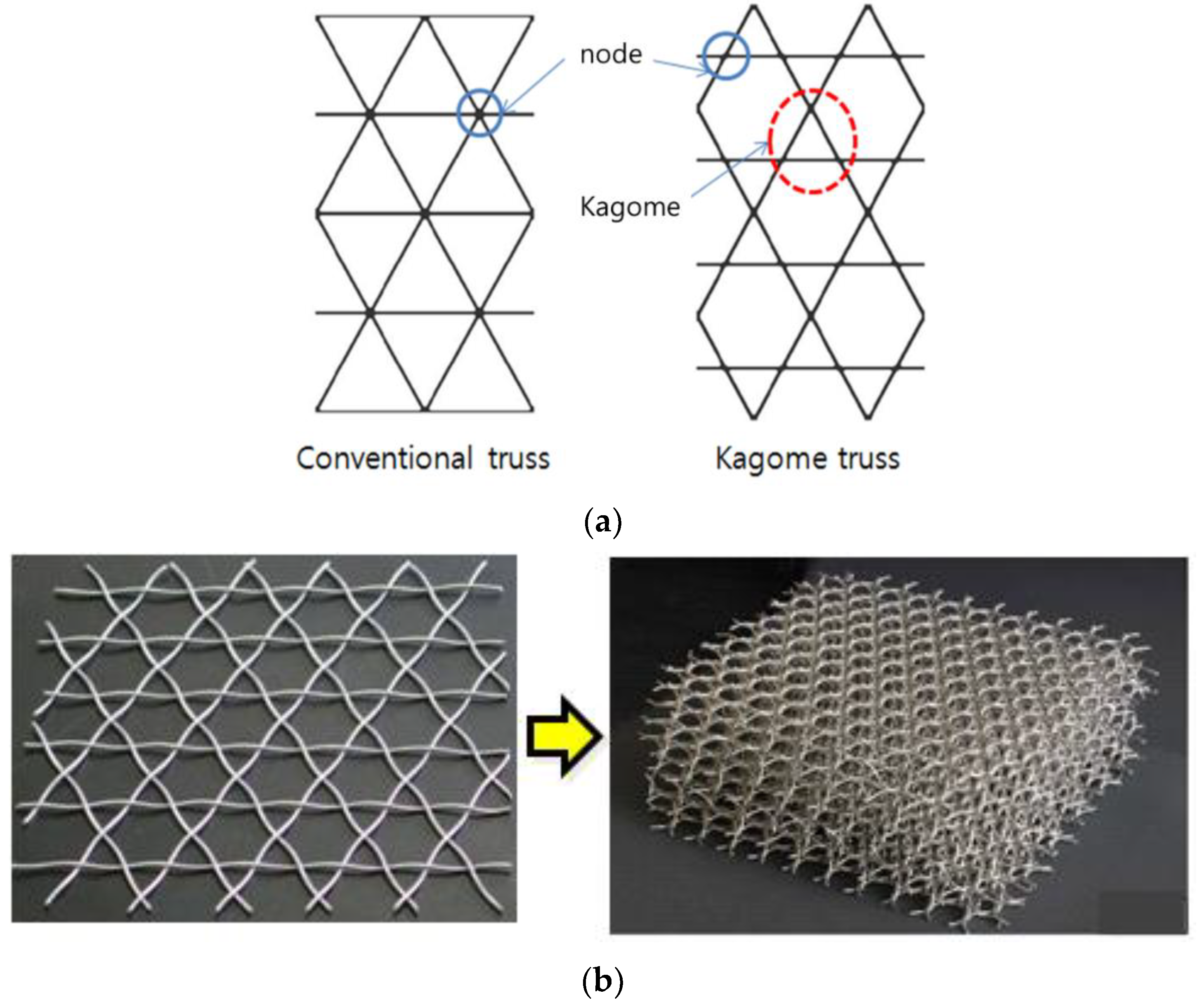
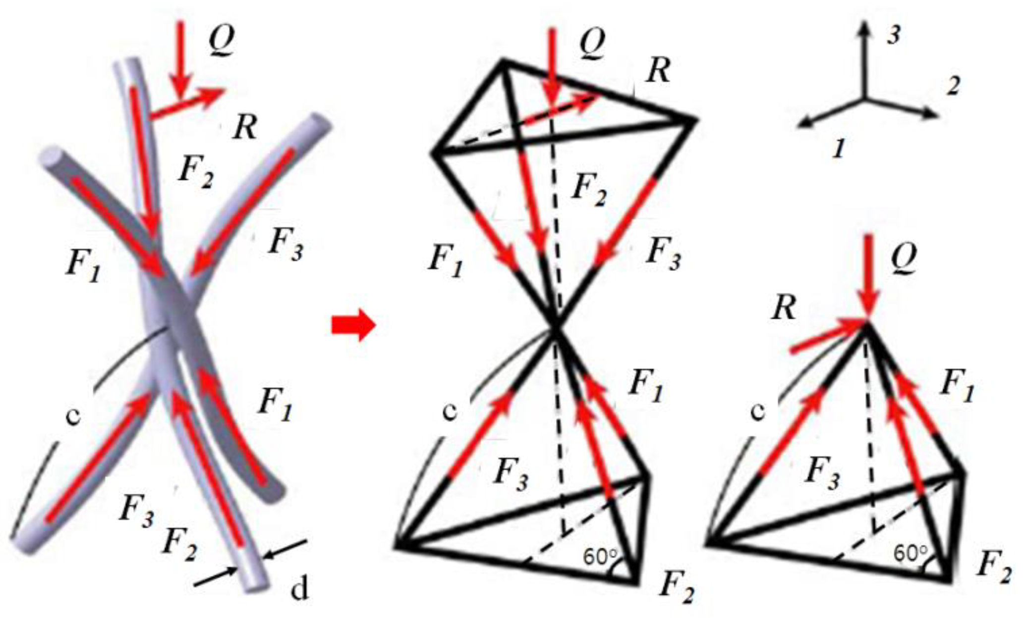
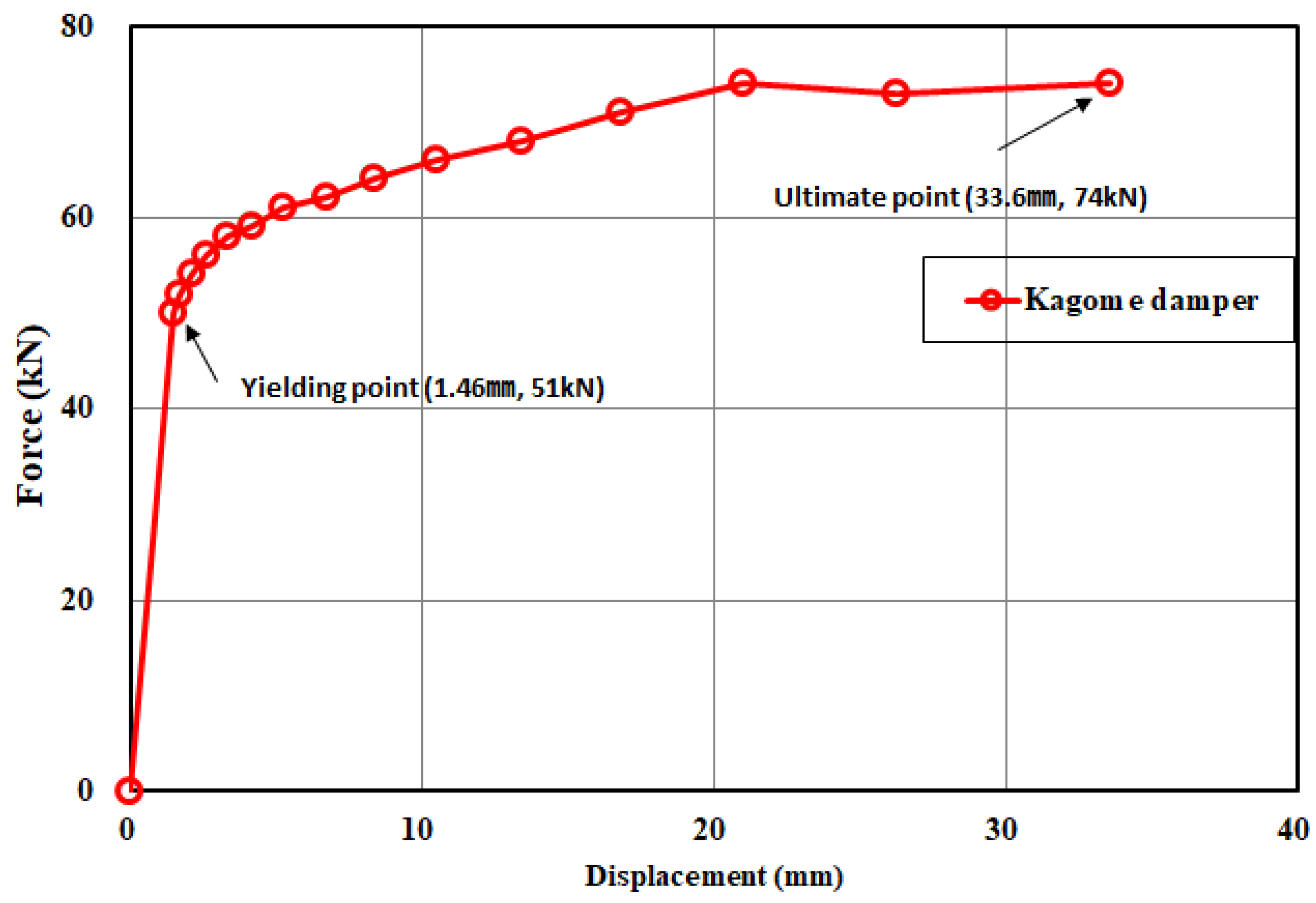
2.1. Metal-Wire Kagome Truss Damper
2.2. Properties of Idealized Shear Behavior
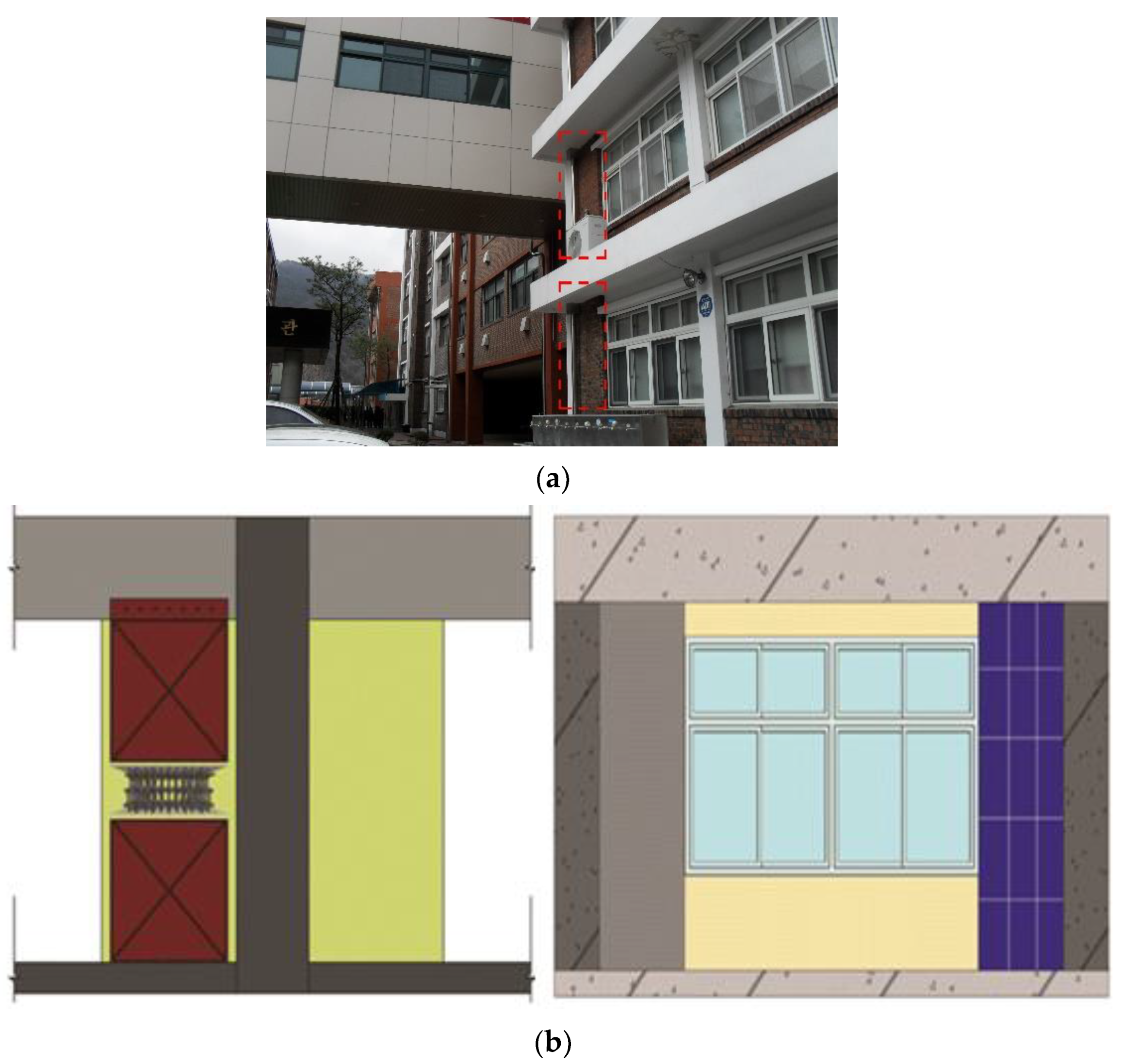
2.3. Model Structure and Test Specimen
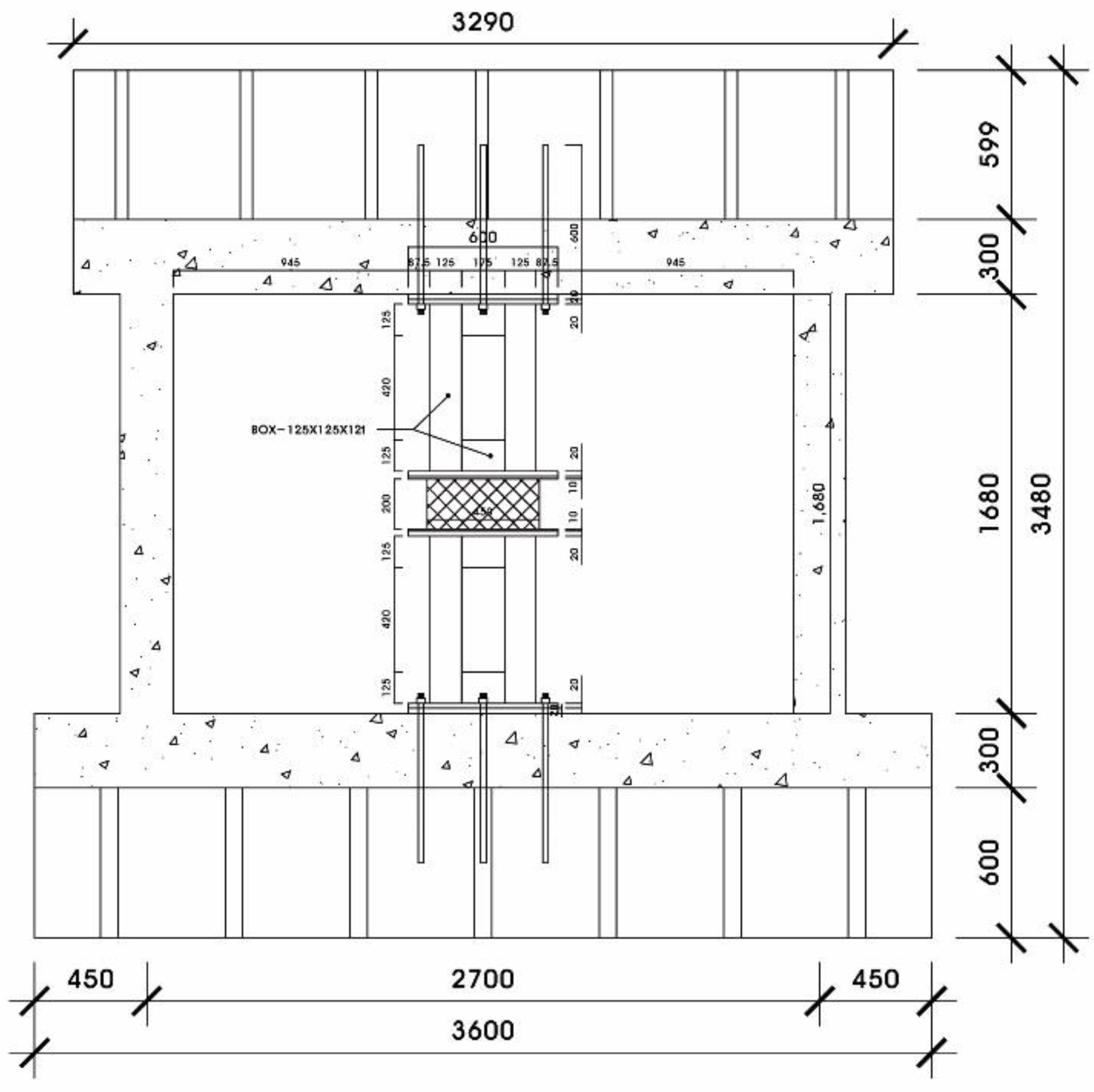
2.4. Design of the Kagome Damper
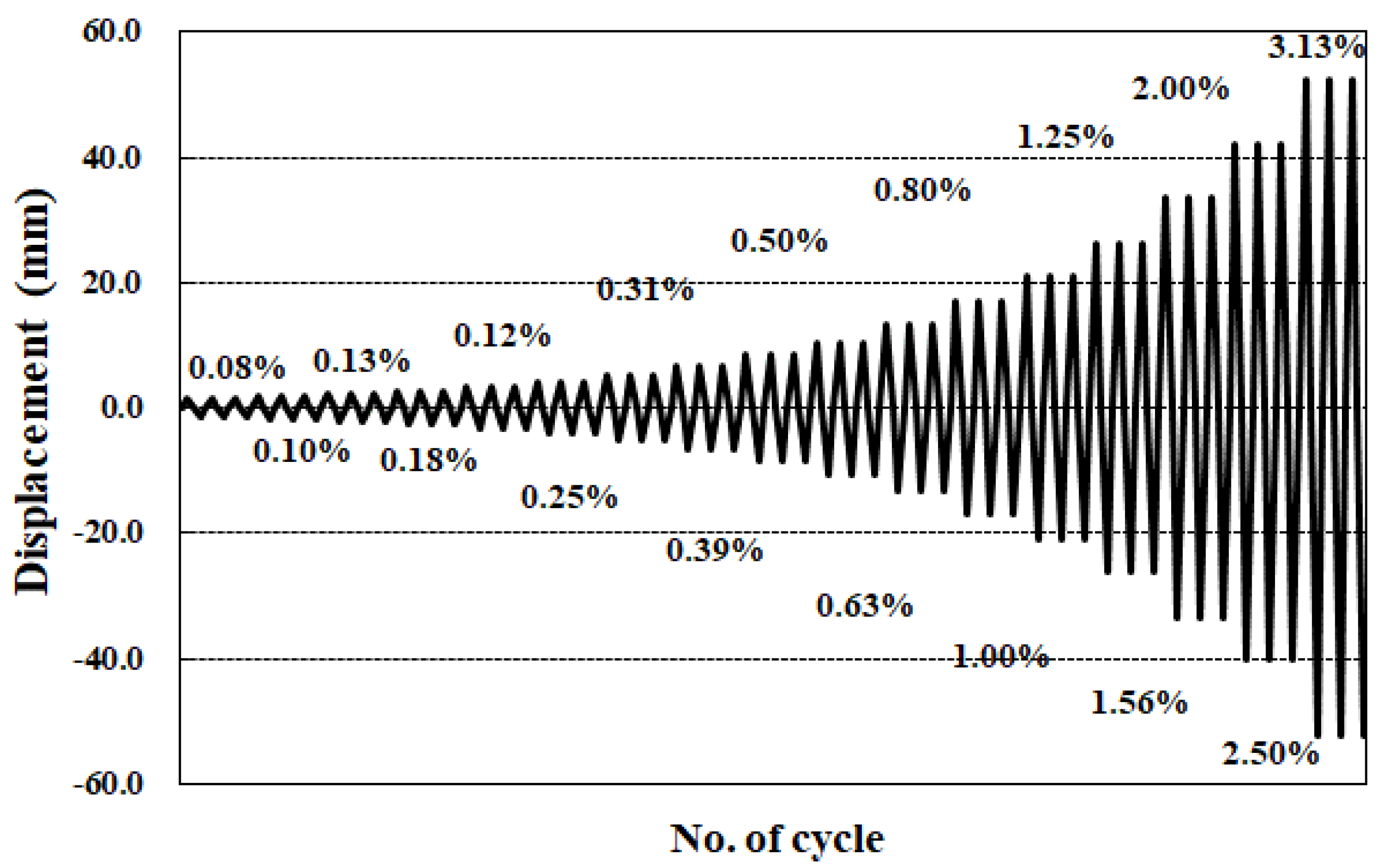
2.5. Test Setup
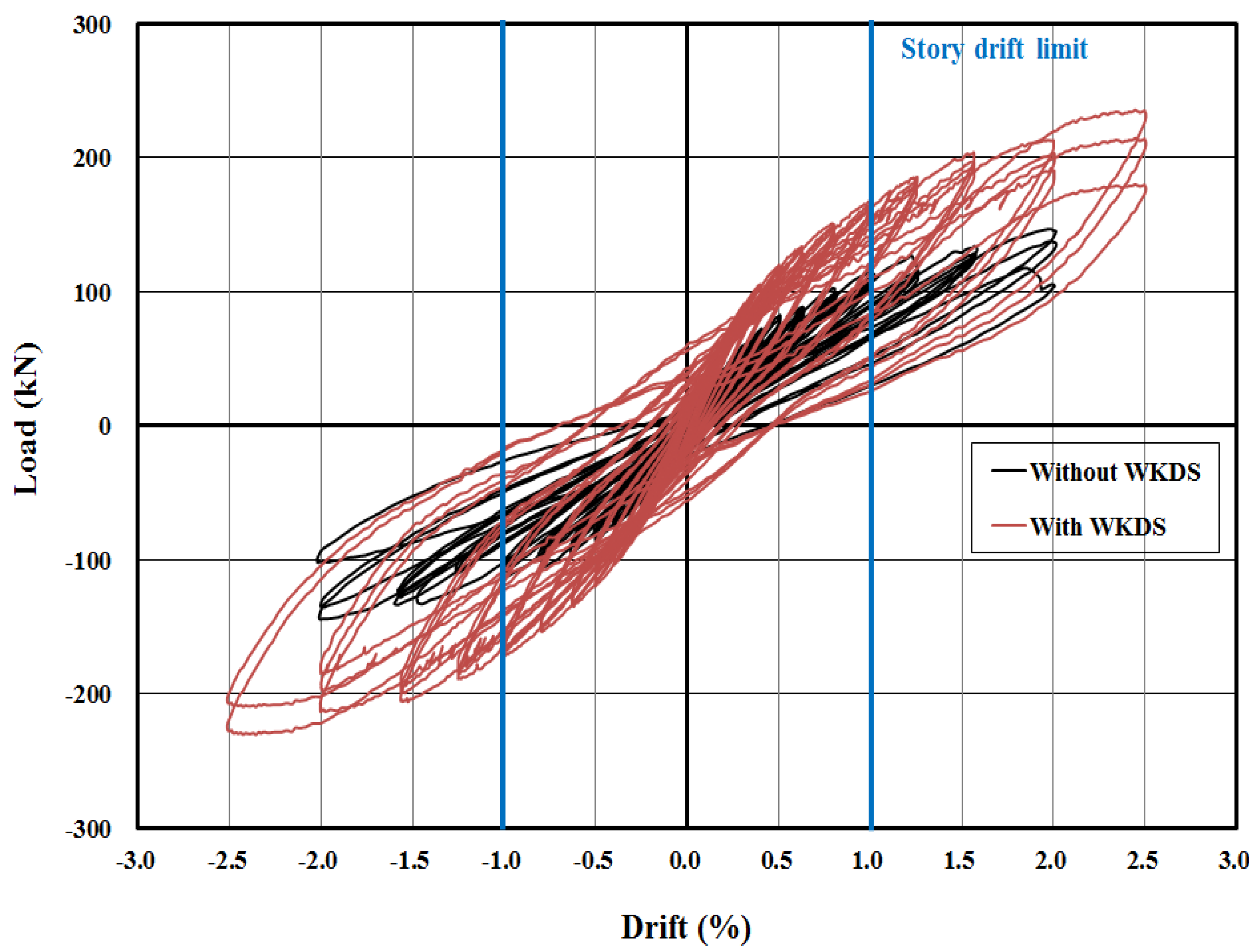
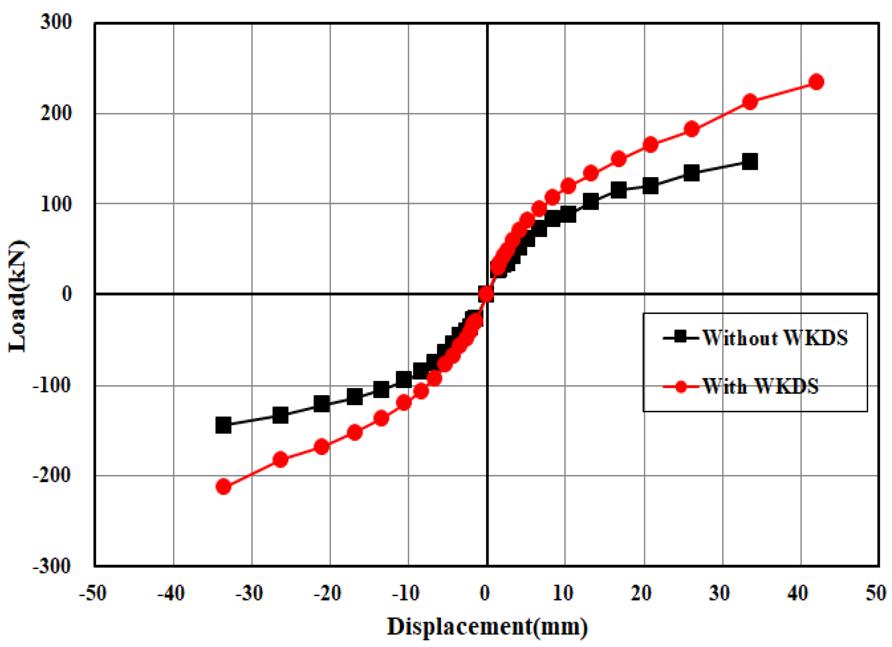
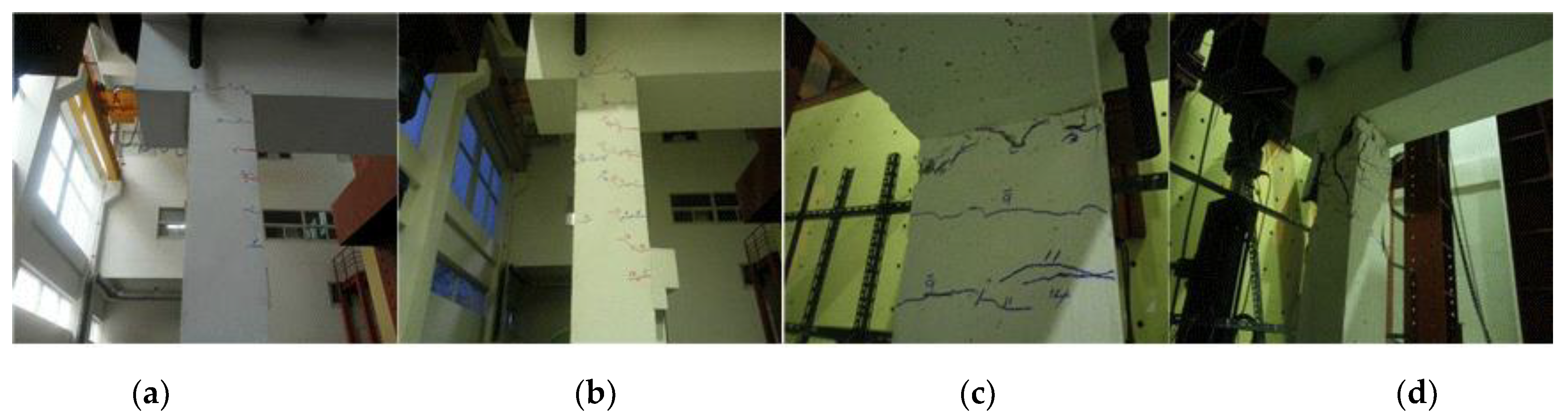
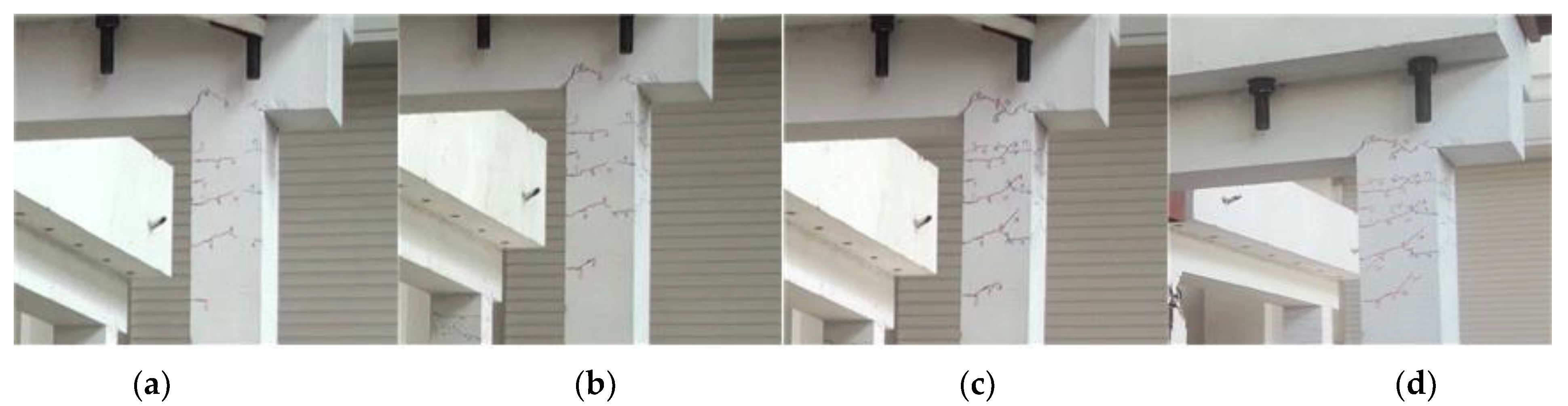
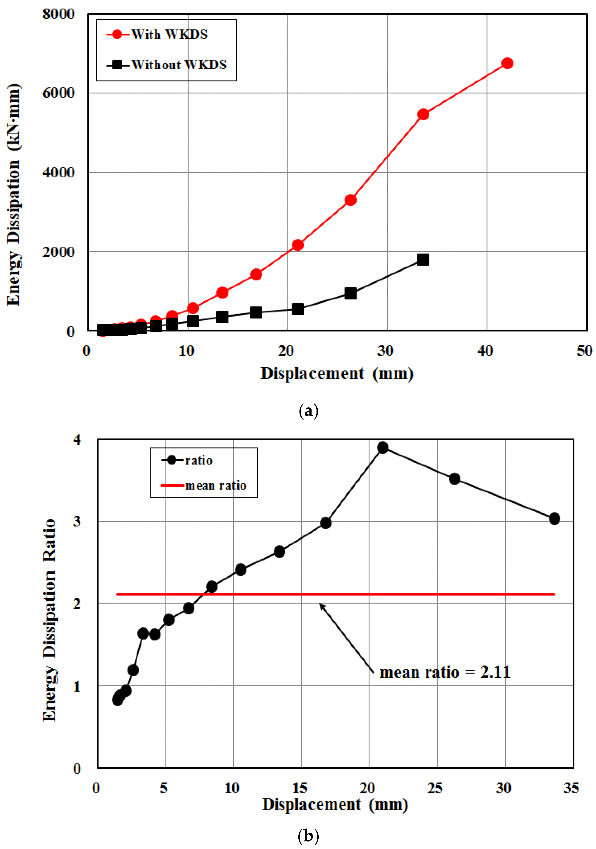
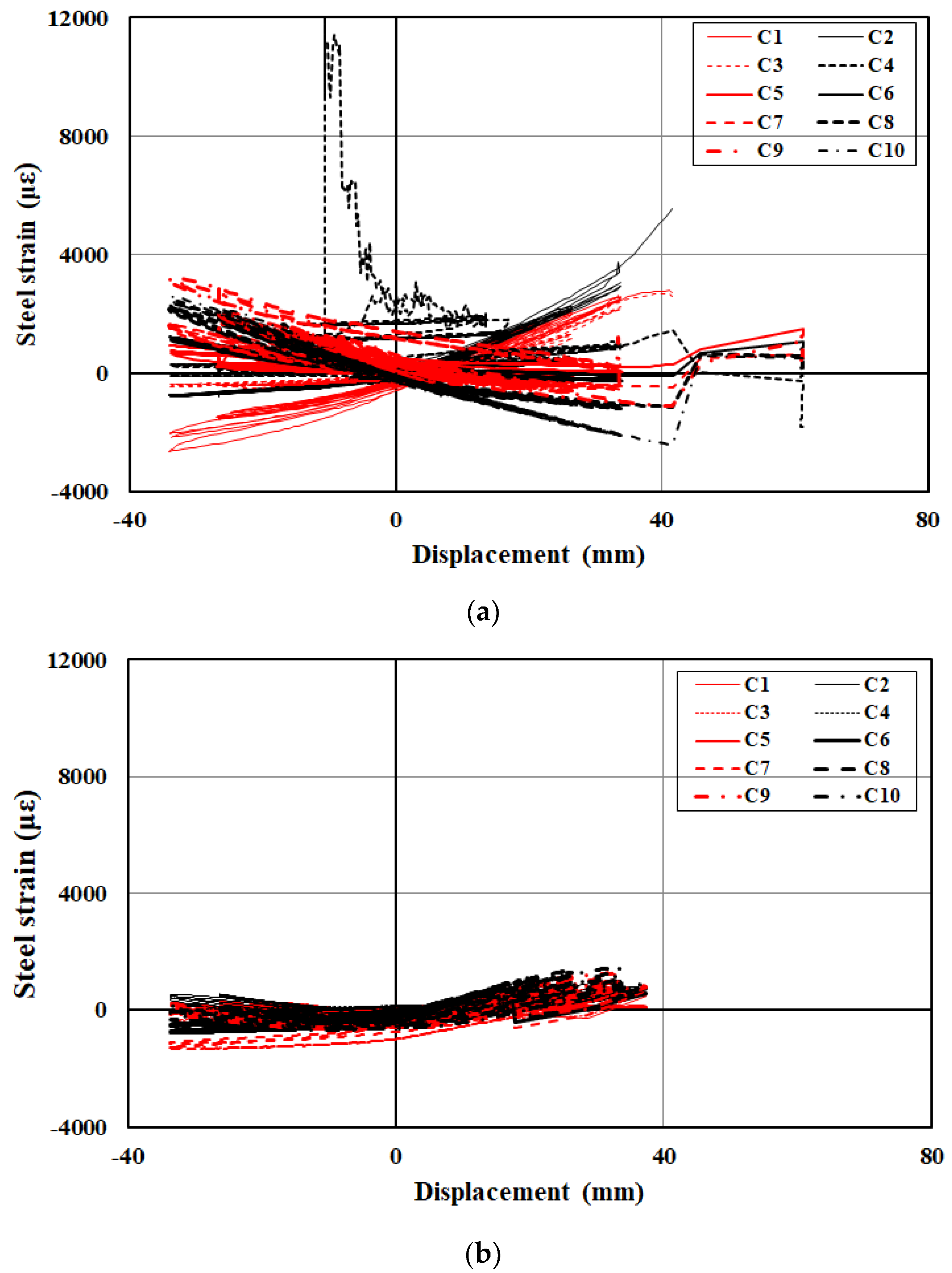
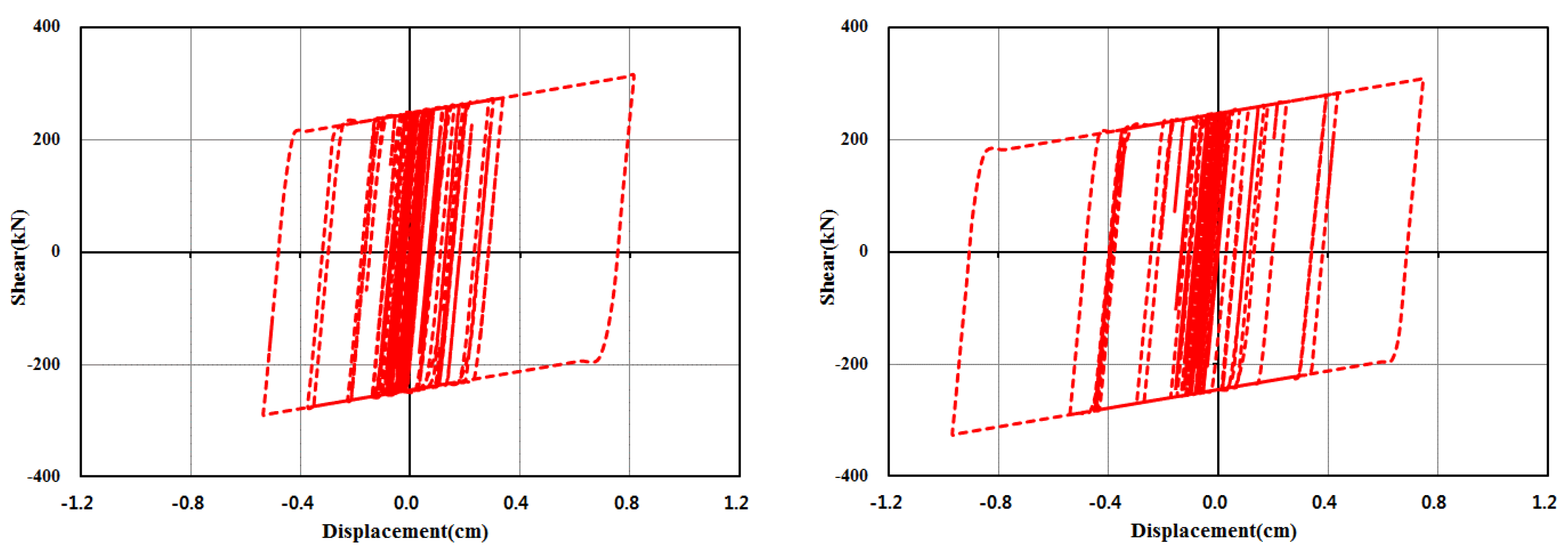
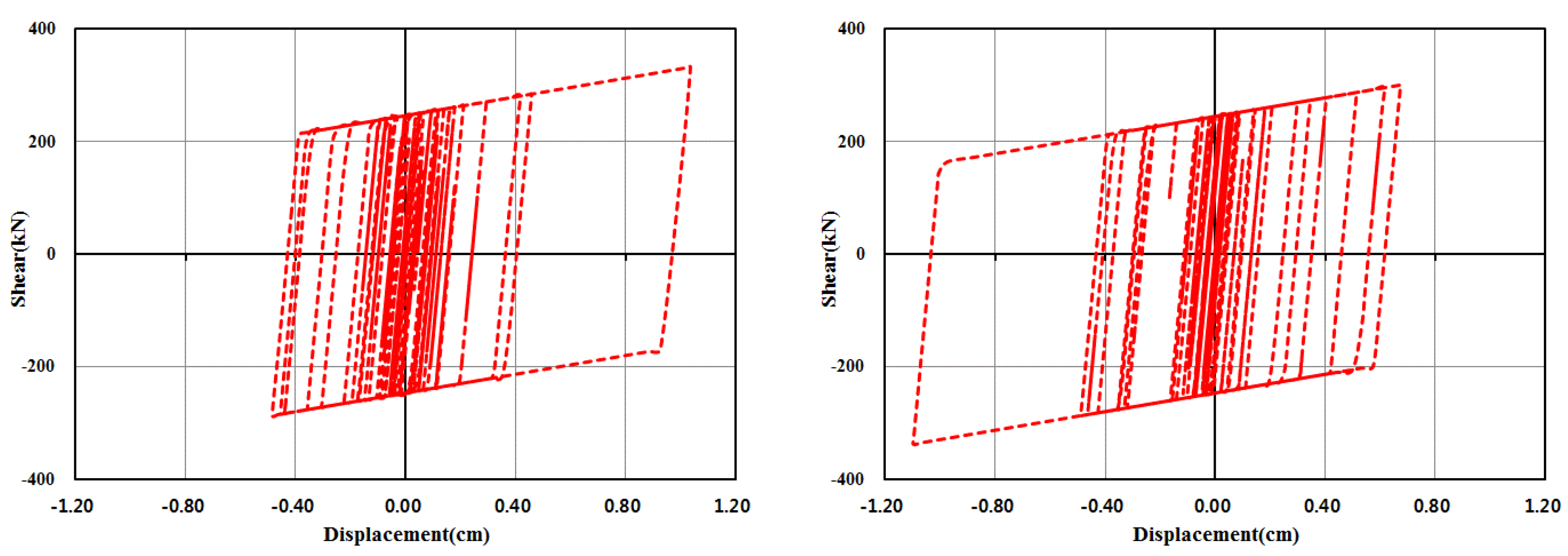
2.6. Test Results
3. Analytical Study
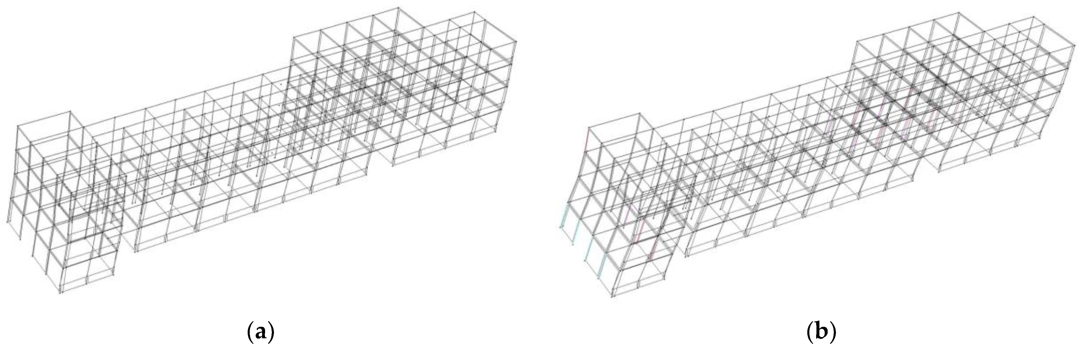
3.1. Building Model
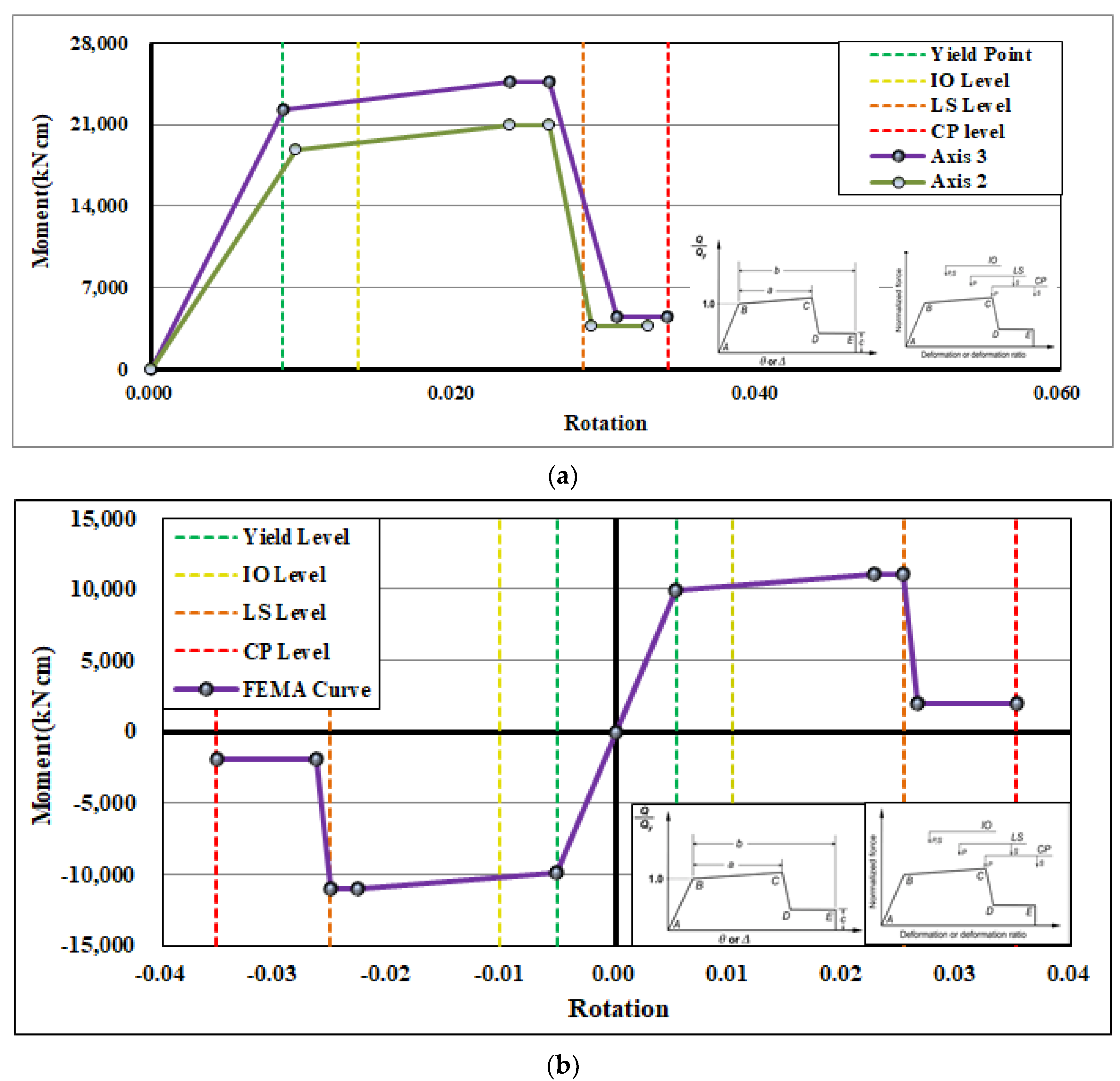
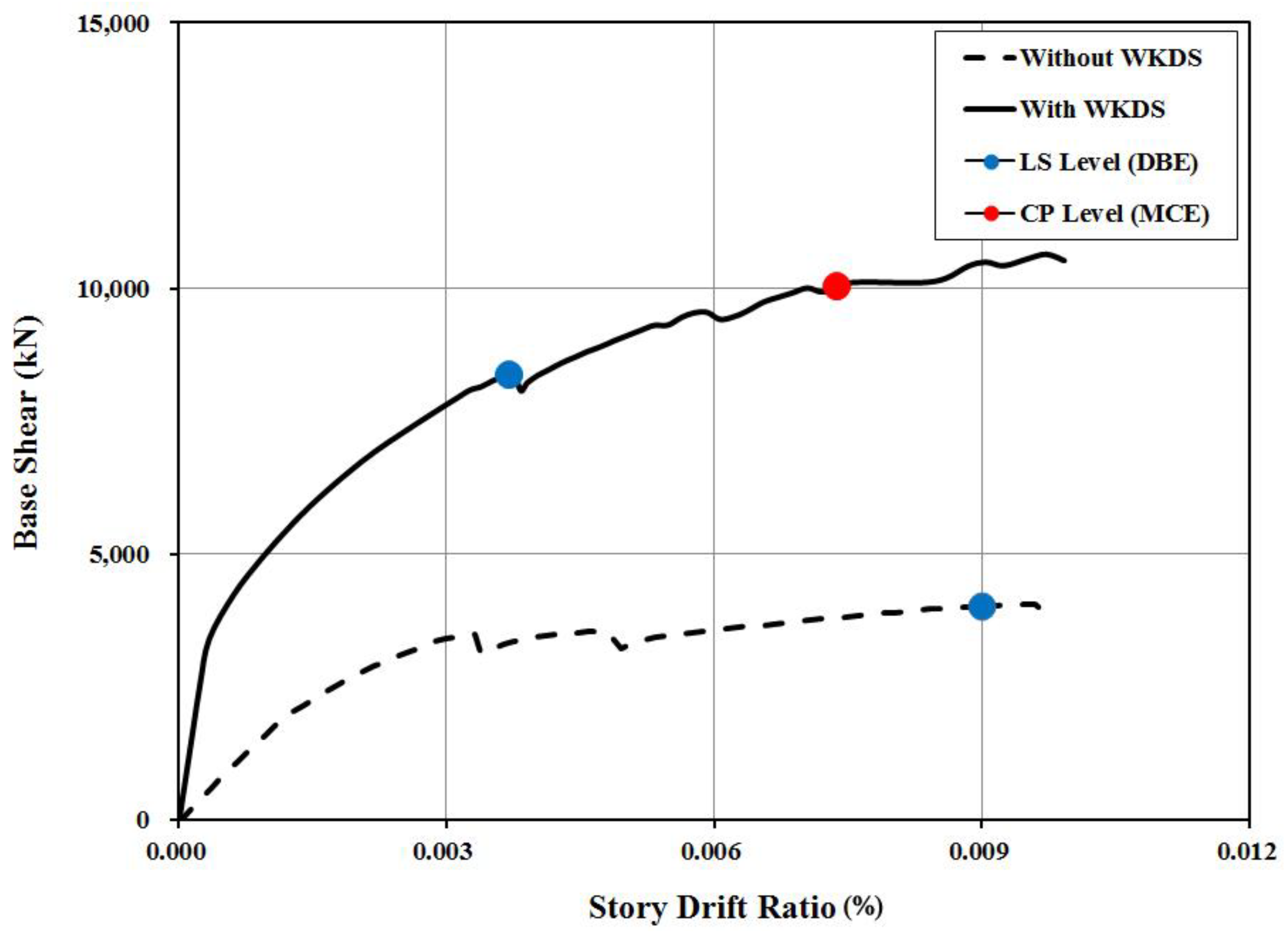
3.2. Nonlinear Static Analysis
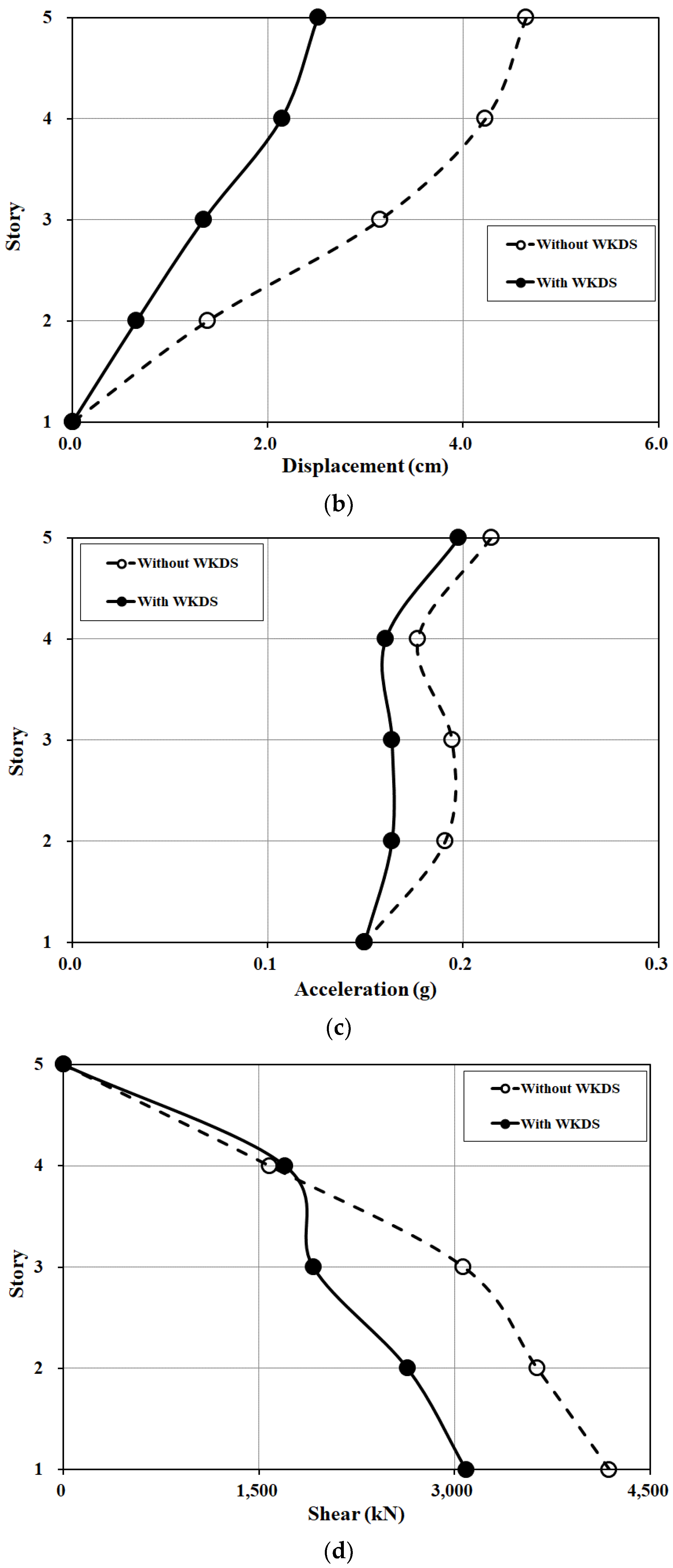
3.3. Nonlinear Dynamic Analysis
3.3.1. Earthquake Records
3.3.2. Result of Nonlinear Time-History Analysis
4. Concluding Remarks
- The results of cyclic loading test results indicate that both the stiffness and the strength of a RC frame structure could effectively be enhanced by the WKDS. The unreinforced structure suffered brittle shear failure at the end of the column at 2.0% as a drift ratio, while the retrofitted structure by the WKDS still had been dissipating energy stably by the same drift ratio. The maximal resisting lateral load of the retrofitted structure, as predicted in the numerical analysis, was increased by 1.5 times higher than that of the unreinforced structure. Ultimately, the results suggest that the WKDS is an effective apparatus to mitigate strength degradation improving energy dissipation capacity;
- It was analytically verified in the nonlinear static and dynamic analyses that the WKDS suppresses the seismic response of the building structure owing to its hysteretic characteristics, as identified in the cyclic loading test. Specifically, the WKDS effectively reduces the drift and displacement responses of the RC frame such that damage of existing buildings can be mitigated substantially even in cases of severe seismic events;
- In a numerical study of an existing four-story RC school building to verify the efficacy of WKDSs in reducing the seismic responses of building structures, it was clear that the drift and displacement of the structure rehabilitated by using WKDSs reduced by 50% of those of the unreinforced structure. The reductions of the absolute acceleration and the base shear were not as large as the displacement response reduction since the building was stiffened and strengthened by the WKDS.
Author Contributions
Funding
Data Availability Statement
Conflicts of Interest
References
- Tsionis, G.; Bossi, A.; Pinto, A.; Marazzi, F. The L’Aquila, Italy Earthquake of 6 April 2009. In Earthquake Engineering Report 2009; Institute for the Protection and Security of the Citizen: Ispra, Italy, 2011. [Google Scholar]
- Zhao, B.; Taucer, F.; Rossettob, T. Field investigation on the performance of building structures during the 12 May 2008 Wenchuan earthquake in China. Eng. Struct. 2009, 31, 1707–1723. [Google Scholar] [CrossRef]
- Sezen, H.; Elwood, K.J.; Whittaker, A.S.; Mosalan, K.M.; Wallace, J.W.; Stanton, J.F. Structural Engineering Reconnaissance of the August 17, 1999 Earthquake: Kocaeli (Izmit), Turkey; Technical Report; Pacific Engineering Research Center, University of California: Berkeley, CA, USA, 2000. [Google Scholar]
- Tsai, K.C.; Hsiao, C.P.; Bruneau, M. Overview of Building Damages in 921 Chi-Chi Earthquake. Earthq. Eng. Eng. Seismol. 2000, 2, 93–108. [Google Scholar]
- Verderame, G.M.; de Luca, F.; Ricci, P.; Manfredi, G. Preliminary analysis of a soft-story mechanism after the 2011 L’Aquila earthquake. Earthq. Eng. Struct. Dyn. 2011, 40, 925–944. [Google Scholar] [CrossRef] [Green Version]
- Skinner, R.I.; Kelly, J.M.; Heine, A.J. Hysteretic dampers for earthquake-resistant structures. Earthq. Eng. Struct. Dyn. 1974, 3, 287–296. [Google Scholar] [CrossRef]
- Whittaker, A.S.; Bertero, V.V.; Thompson, C.L.; Alonso, L.J. Seismic Testing of Steel Plate Energy Dissipation Devices. Earthq. Spectra 1991, 7, 563–604. [Google Scholar] [CrossRef]
- Tsai, K.C.; Chen, H.-W.; Hong, C.C.; Su, Y.F. Design of Steel Triangular Plate Energy Absorbers for Seismic-Resistant Construction. Earthq. Spectra 1993, 9, 505–528. [Google Scholar] [CrossRef]
- Benavent, C.A.; Oh, S.H.; Akiyama, H. Ultimate energy absorption capacity of slit-type steel plates subjected to shear deformation. J. Struct. Constr. Eng. 1998, 503, 139–147. [Google Scholar] [CrossRef] [Green Version]
- Bincy, V.; Usha, S. Seismic performance evaluation of steel building frames with modified dual-pipe damper. IOP Conf. Ser. Mater. Sci. Eng. 2021, 1114, 012004. [Google Scholar] [CrossRef]
- Saingam, P.; Sutcu, F.; Terazawa, Y.; Celik, O.C.; Takeuchi, T. Seismic Retrofit of RC Buildings with Viscous Dampers and Elastic Steel Frames including Effect of Composite Behavior. J. Struct. Eng. B 2021, 67, 569–580. [Google Scholar]
- Idels, O.; Lavan, O. Optimization-based seismic design of steel moment-resisting frames with nonlinear viscous dampers. Struct. Control Health Monit. 2021, 28, e2655. [Google Scholar] [CrossRef]
- Taiyari, F.; Mazzolani, F.M.; Bagheri, S. A proposal for energy dissipative braces with U-shaped steel strips. J. Constr. Steel Res. 2019, 154, 110–122. [Google Scholar] [CrossRef]
- Lin, X.; Wu, K.; Skalomenos, K.A.; Lu, L.; Zhao, S. Development of a buckling-restrained shear panel damper with demountable steel-concrete composite restrainers. Soil Dyn. Earthq. Eng. 2019, 118, 221–230. [Google Scholar] [CrossRef]
- Yamazaki, S.; Usami, T.; Nonaka, T. Developing a new hysteretic type seismic damper (BRRP) for steel bridges. Eng. Struct. 2016, 124, 286–301. [Google Scholar] [CrossRef]
- Tagawa, H.; Yamanishi, T.; Takaki, A.; Chan, R.W.K. Cyclic behavior of seesaw energy dissipation system with steel slit dampers. J. Constr. Steel Res. 2016, 117, 24–34. [Google Scholar] [CrossRef]
- Chan, R.W.K.; Yuen, J.K.K.; Lee, E.W.M.; Arashpour, M. Application of Nonlinear-Autoregressive-Exogenous model to predict the hysteretic behaviour of passive control systems. Eng. Struct. 2015, 85, 1–10. [Google Scholar] [CrossRef]
- Infanti, S.; Papanikolas, P.; Benzoni, G.; Castellano, M.G. RION-ANTIRION bridge: Design and full-scale testing of the seismic protection devices. In Proceedings of the 13th World Conference on Earthquake Engineering, Vancouver, BC, Canada, 1–6 August 2004. [Google Scholar]
- Milani, A.S.; Dieleli, M. Systematic development of a new hysteretic damper based on torsional yielding: Part-Ι—Design and development. Earthq. Eng. Struct. Dyn. 2015, 45, 845–867. [Google Scholar] [CrossRef]
- Wadley, H.N.G.; Fleck, N.A.; Evans, A.G. Fabrication and structural performance of periodic cellular metal sandwich structures. Compos. Sci. Technol. 2003, 63, 2331–2343. [Google Scholar] [CrossRef]
- Kang, K.J. Development of Production Technology of Truss Type Periodic Cellular Metal; National Designated Laboratory Project, Korea Science and Engineering Foundation: Daejeon, Korea, 2011. [Google Scholar]
- Lee, B.K.; Kang, K.J. A parametric study on compressive characteristics of Wire-woven bulk Kagome truss cores. Compos. Struct. 2010, 92, 445–453. [Google Scholar]
- Lee, B.K.; Choi, J.E.; Jeon, I.S.; Kang, K.J. Analysis of Compressive Characteristics of Wire-woven Bulk Kagome. J. Korean Soc. Mech. Eng. 2008, 32, 70–76. [Google Scholar] [CrossRef]
- Lee, M.J. Compressive Characteristics of Two New Types of Periodic Cellular Metals. Master’s Thesis, Graduate School, Chonnam National University, Gwangju, Korea, August 2009. [Google Scholar]
- Park, J.S.; Joo, J.H.; Lee, B.C.; Kanf, K.J. Mechanical behaviour of tube-woven Kagome truss cores under compression. Int. J. Mech. Sci. 2010, 53, 65–73. [Google Scholar] [CrossRef]
- Lee, Y.H.; Kang, K.J. An Optimal Design of Sandwich Panels with Wire-woven Bulk Kagome Cores. J. Korean Soc. Mech. Eng. 2008, 32, 782–787. [Google Scholar] [CrossRef]
- Hwang, J.S.; Lee, K.S. Seismic Strengthening Effects Based on Pseudodynamic Testing of a Reinforced Concrete Building Retrofitted with a Wire-Woven Bulk Kagome Truss Damper. Shock. Vib. 2016, 2016, 3956126. [Google Scholar] [CrossRef]
- Hwang, J.S.; Lee, K.S.; Hur, M.W.; Lee, S.H. Mechanical hysteresis model of a metal-wire Kagome truss for seismic strengthening for building systems. J. Asian Archit. Build. Eng. 2019, 18, 112–120. [Google Scholar] [CrossRef]
- Beak, E.L.; Oh, S.H.; Lee, S.H. Seismic performance of an Existing Low-Rise Reinforced Concrete Piloti Building Retrofitted by Steel Rod Damper. J. Earthq. Eng. Soc. Korea 2014, 18, 241–251. [Google Scholar] [CrossRef] [Green Version]
- ASCE. ASCE/SEI 41-17. Seismic Evaluation and Retrofit of Existing Buildings; American Society of Civil Engineers: Reston, VA, USA, 2017. [Google Scholar]
- Applied Technology Council. Improvement of Static Seismic Analysis Procedures; FEMA 440 Report 2005; Applied Technology Council: Redwood City, CA, USA, 2005. [Google Scholar]


| Content | Full Scale | 60% Scale | Remarks |
|---|---|---|---|
| Column | 500 × 350 mm | 300 × 210 mm | - |
| Story | 3300 mm | 1980 mm | Beam included |
| Axial load | 5060 kN: (2530 kN/column) | 180 kN (90 kN/column) |
|
| Span | 4500 mm | 2700 mm |
| No | Concrete Strength | Modulus of Elasticity | Bar Size | Yield Strength | Yield Strain (×10−5) | Tensile Strength | Elongation (%) | |
|---|---|---|---|---|---|---|---|---|
| fck | fck. ave. | |||||||
| 1 | 20.45 | 20.53 | 1.96 × 10⁴ | D13 | 348.03 | 2960.3 | 517.41 | 36.0 |
| 2 | 21.21 | |||||||
| 3 | 19.45 | D10 | 299.55 | 4205.8 | 418.6 | 26.8 | ||
| 4 | 18.37 | |||||||
| 5 | 22.56 | 12T | 332.01 | 1919.0 | 477.3 | 26.8 | ||
| 6 | 21.12 | |||||||
| Specimen | Loading Direction | Yield Load (kN) | Yield Displacement (δy, mm) | Maximum Load (kN) | Maximum Displacement (δmax, mm) |
|---|---|---|---|---|---|
| Without WKDS | + | 82.7 | 8.4 | 146.9 | 33.6 |
| − | −85.2 | −8.4 | −144.2 | −33.6 | |
| With WKDS | + | 107.0 | 8.4 | 234.0 | 42.0 |
| − | −106.6 | −8.4 | −226.9 | −42.0 |
| Element | a | b | c | IO | LS | CP | |
|---|---|---|---|---|---|---|---|
| Column (350 × 400 mm) | Axis 3 | 0.032 | 0.060 | 0.20 | 0.005 | 0.045 | 0.060 |
| Axis 2 | 0.032 | 0.060 | 0.20 | 0.005 | 0.045 | 0.060 | |
| Girder (350 × 400 mm) | Upper | 0.032 | 0.060 | 0.20 | 0.005 | 0.045 | 0.060 |
| Bottom | 0.032 | 0.060 | 0.20 | 0.005 | 0.045 | 0.060 | |
| Building | Displacement | Acceleration | Shear (kN) | Drift Ratio |
|---|---|---|---|---|
| Without WKDS (a) | 46.4 mm | 0.214 g | 4185 kN | 0.0056 |
| With WKDS (b) | 25.2 mm | 0.198 g | 3088 kN | 0.0026 |
| Reduction Ratio (b/a) | 0.54 | 0.92 | 0.74 | 0.47 |
Publisher’s Note: MDPI stays neutral with regard to jurisdictional claims in published maps and institutional affiliations. |
© 2022 by the authors. Licensee MDPI, Basel, Switzerland. This article is an open access article distributed under the terms and conditions of the Creative Commons Attribution (CC BY) license (https://creativecommons.org/licenses/by/4.0/).
Share and Cite
Hur, M.-W.; Lee, Y.; Jeon, M.-J.; Lee, S.-H. Seismic Strengthening of RC Structures Using Wall-Type Kagome Damping System. Buildings 2022, 12, 41. https://doi.org/10.3390/buildings12010041
Hur M-W, Lee Y, Jeon M-J, Lee S-H. Seismic Strengthening of RC Structures Using Wall-Type Kagome Damping System. Buildings. 2022; 12(1):41. https://doi.org/10.3390/buildings12010041
Chicago/Turabian StyleHur, Moo-Won, Yonghun Lee, Min-Jun Jeon, and Sang-Hyun Lee. 2022. "Seismic Strengthening of RC Structures Using Wall-Type Kagome Damping System" Buildings 12, no. 1: 41. https://doi.org/10.3390/buildings12010041