Article

Selection of Ground Motion Intensity Measures in Fragility Analysis of a Mega-Scale Steel Frame Structure at Separate Limit States: A Case Study

1
College of Civil Engineering, Nanjing Forestry University, Nanjing 210037, China
2
College of Civil and Transportation Engineering, Hohai University, Nanjing 210098, China
3
College of Civil Engineering and Architecture, Shandong University of Science and Technology, Qingdao 266590, China
4
Arup International Consultants (Shanghai) Co., Ltd., Shanghai 200031, China
*
Author to whom correspondence should be addressed.
Buildings 2022, 12(10), 1530; https://doi.org/10.3390/buildings12101530
Submission received: 3 September 2022 / Revised: 18 September 2022 / Accepted: 21 September 2022 / Published: 26 September 2022
(This article belongs to the Special Issue New Trends in Seismic Performance Evaluation)

Abstract

:
Selecting an appropriate ground motion intensity measure (IM) to estimate the aleatory uncertainty produced by ground motion variability is the first and crucial step in fragility analysis. The choice of IM is influenced not only by the structural system type itself but also by the limit state of the structural damage. In this study, an investigation of the selection of IM in fragility analysis with respect to different limit states is developed for a 48-story mega-scale steel frame structure with buckling restrained braces. A comparative study of the efficiency of 27 IMs is conducted at four structural damage limit states, i.e., negligible, light, moderate, and severe, through the lognormal standard deviation estimated in fragility equations. In addition, for the purpose of considering the influence of different earthquake characteristics, two completely different sets of ground motions are selected, namely near-field pulse-like and far-field earthquakes. The research shows that the ground motion characteristics and structural damage limit states have nonnegligible effects on the flexibility of intensity measures. For combination-type IMs, the number of combined terms and the combined power index have a significant impact on their performance; thus, an optimized dual-parameter combination-type intensity measure is recommended.

1. Introduction

Over the past 40 years of economic development, super tall buildings have been extensively developed in China. As a kind of super high-rise building structure system, a mega-scale frame structure, which is composed of mega columns and beams with larger column spacing, has been applied due to its excellent architectural and structural performance. The primary and secondary structures of the mega-scale frame structure system have clear transmission of forces and flexible layout, which can meet the requirements of special architectural forms and functions. Therefore, it is logical to implement a seismic fragility analysis for such structures and to grasp the seismic performance of such structures [1,2,3,4,5,6,7,8,9,10,11,12,13]. However, there is less efficient analysis of the seismic fragility for mega-scale frame structures.
Selecting an appropriate intensity measure (IM), which describes the record-to-record uncertainty, is the principal and crucial step in seismic fragility analysis. As an intermediate variable, the ground motion IM links the seismic hazard and building performance demand measure (DM) in the process of analysis. To date, various IMs have been recommended for diverse building structures [14,15,16,17,18,19,20,21]. Meanwhile, the selection of measures depends on both the structural system and the DM concerned. For super tall buildings, research has been conducted on the flexibility of IMs in the estimation of DM. For distinctive frame core-tube structural systems, the performance of ground motion IMs in estimating the floor acceleration [20] and structural damage demand [18,19,21] is explored. The choice of ground motion IMs is also related to the seismic structural damage limit state of concern [22,23]. Nevertheless, exploration of the seismic fragility of mega-scale frame structures is seldom conducted in-depth.
The choice of the appropriate IM in the seismic structural fragility analysis of mega-scale frame structures in four different limit states is analyzed in this study. The influence of earthquake characteristics is considered; that is, near-field pulse-like and far-field records are selected. A 192-m-high and 48-story mega-scale steel frame structure is selected here as the analysis object. The results are obtained by the multiple stripes analysis (MSA) method [24], which requires less computational effort in this scenario compared to the incremental dynamic analysis (IDA) method [25]. The appropriate ground motion IM is screened by analyzing the logarithmic standard deviation βRTR obtained in the fragility equations corresponding to each limit state. Through an in-depth analysis of the correlation between structural damage and spectral acceleration over the whole domain, the combination-type intensity measure is optimized, and the corresponding parameters are suggested for different types of ground motion.

2. Basic Information

2.1. 48-Story Mega-Scale Steel Frame Structure

A 192-m-high and 48-story mega-scale steel frame structure is selected, as shown in Figure 1, which consists of five bays in each direction, with a span distance of 8 m, and each story’s height of the building is 4 m. To better ensure the seismic performance, the structure is strengthened with the mass of buckling restrained braces (BRBs). The structure is designed according to the Chinese Seismic Design of Buildings Code GB50011-2010 [26]. Details, including structural dimensions and material parameters, are listed in Table 1. The live load generated on each slab is 2.0 kN/m2, the self-weight dead load applied on each slab and the roof is 3.5 kN/m2, and the roof has an additional dead load of 3.32 kN/m2. The frame is located in an earthquake high risk area with seismic fortification intensity of 8 (0.2 g), site soil of class II, and design group of 1. More information is available in Sun et al. [27].
The frame structure is modeled using the open-source software platform OpenSEES, which is developed by the Pacific Earthquake Engineering Research (PEER) Center [28,29]. All columns and beams are simulated using a dispBeamColumn element in OpenSEES, which is based on the displacement-based Euler–Bernoulli beam theory. In addition, the BRB portions are simulated using truss elements, in which the uniaxial stress–strain relationship is described by utilizing the Giuffre–Menegotto–Pinto (GMP) model. A damping ratio of 0.02 is assumed during Rayleigh damping. More information on numerical modeling can be found in Sun et al. [27]. The first five periods corresponding to the N–S direction of the steel frame building are provided in Table 2.

2.2. Selection of Ground Motions

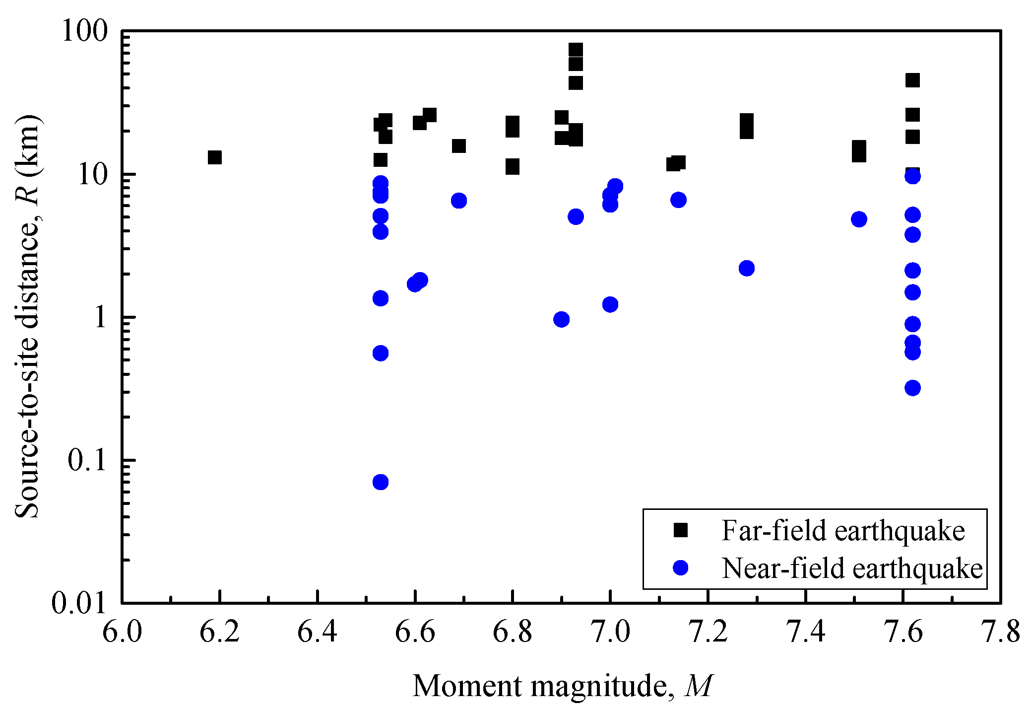
To fully reflect the ground motion randomness, two groups’ records with different properties, i.e., far-field and near-field pulse-like, are screened out, with 30 ground motions in each group, as shown in Table 3, from the Pacific Earthquake Engineering Research Center (PEER) ground motion database [30]. Detailed information on the selected records, for instance, the corresponding peak ground acceleration (PGA), can be found in Zhang et al. [18,20]. The wavelet analysis theory recommended by Baker [31] was employed to screen near-field pulse-like records. The selection criteria for these two groups of ground motion records follow the method provided in FEMA P695 [32] and take the dynamic characteristics of tall buildings into account. The source-to-site distance limit of far-field and near-field records is set to 10 km, and the moment magnitude is above 6, as shown in Figure 2. The lowest frequency at a maximum of 0.1 Hz of the selected record is lower than the frequency of the structure [18,20]. The lowest frequency refers to the frequency at which the frequency spectrum of the data after high-pass filtering is relatively unaffected by the filter. The strong earthquake records recommended by FEMA P695 that meet these requirements are retained.

2.3. Selection of Optimal Intensity Measures

In this study, 27 IMs are selected for comparative investigation, as shown in Table 4. The IMs associated with the amplitude of ground motion, i.e., peak ground acceleration (PGA), peak ground velocity (PGV), peak ground displacement (PGD), sustained maximum acceleration (SMA), sustained maximum velocity (SMV), effective design acceleration (EDA), and V/A (i.e., PGV/PGA [33]), are included. The sustained maximum acceleration (SMA) and sustained maximum velocity (SMV) define the third peak in the time history of ground motions [34]. Benjamin and associates [35] believe that high-frequency ground motion components have little impact on the seismic damage of the structure, and components with a frequency higher than 8–9 Hz in the acceleration time history are filtered out. The peak value of the filtered acceleration time history is defined as the effective design acceleration (EDA).
Many spectrum-based IMs are also considered. The maximum response of a single degree of freedom structure corresponding to the fundamental period is often used to describe the spectral characteristics of records, i.e., the spectral acceleration Sa(T1), spectral velocity Sv(T1), and spectral displacement Sd(T1) at the first vibration period. The ground motion IMs in integral form over multiple frequency spectral values, i.e., HI [36], ASI, and VSI [37], are selected. Similarly, the combination-type ground motion IMs based on Sa(T1) are also considered. Among them, some reflect the influence of higher mode shapes, i.e., S a 12 * , S a 123 * , IM12, IM123, SN2, S12, S123, and S ¯ a [38,39,40,41,42], and some consider the effect of the softened period, i.e., S*, IM-CR, IM-SR, INP, SN1 [42,43,44,45], or both effects, i.e., Sa,gm(Ti) [46]. In particular, the ground motion IM considering the higher mode shape is proved to be efficient in the structural damage assessment of high-rise buildings [18,19].
The parameter values of each IM will be determined in combination with the structural characteristics of the 48-story building. For S*, Tf = 2T1; for both IM-CR and IM-SR, RIM is set to be 2; for INP, α = 0.5 and TN = 2T1; for IM12, τa = T1, τb = T2, and β = 1/2; for IM123, τa = T1, τb = T2, τc = T3, β = 1/3, and γ = 1/3; for SN1, C = 1.5 and α = 0.5; SN2, β = 0.5; for S12, the values used for α and β are the values in S a 12 * , i.e., 0.8 and 0.2; for S123, the values used for α, β, and γ are the values in S a 123 * , i.e., 0.8, 0.15, and 0.05; for S ¯ a , according to the equation between the structural fundamental period T1 and the combination term n, the first three vibration periods are adopted, i.e., n = 3; for Sa,gm(Ti), five combination items are adopted, as shown in Table 3, in which T1m is taken as T1 and T2m is taken as T2.
Table 4. Selected ground motion intensity measures.
No.IMDefinitionReference
1PGAPeak ground accelerationN.A.
2PGVPeak ground velocityN.A.
3PGDPeak ground displacementN.A.
4SMAThe third peak in the acceleration time history[34]
5SMVThe third peak in the velocity time history
6EDAThe peak acceleration after filtering out components higher than 9 Hz[35]
7V/AThe ratio of peak ground velocity to peak ground acceleration[33]
8Sa(T1)Spectral acceleration at the first vibration period T1N.A.
9Sv(T1)Spectral velocity at the first vibration period T1N.A.
10Sd(T1)Spectral displacement at the first vibration period T1N.A.
11HI H I = 0.1 2.5 P S v ( t ) d t   ,
PSv(t): pseudospectral velocity
[36]
12ASI A S I = 0.1 0.5 S a ( t ) d t [37]
13VSI V S I = 0.1 2.5 S v ( t ) d t
14S* S = ( S a ( T 1 ) ) 1 α ( S a ( T f ) ) α , Tf: softened period[43]
15IM-CR IM - CR = S a ( T 1 ) 1 α S a ( R IM 3 T 1 ) α
RIM: self-adaptive parameter
[44]
16IM-SR IM - SR = S a ( T 1 ) 1 α S a ( R IM T 1 ) α
17INP I N p = S a ( T 1 ) N p a ,   N p = S a ( T 1 ) S a ( T N ) N / S a ( T 1 )
TN: the maximum period of interest
[45]
18 S a 12 * S a 12 * = 0.80 S a ( T 1 ) + 0.20 S a ( T 2 )
T2: the second vibration period
[38]
19 S a 123 * S a 123 * = 0.80 S a ( T 1 ) + 0.15 S a ( T 2 ) + 0.05 S a ( T 3 )
T3: the third vibration period
20IM12 I M 12 = S a ( τ a , 5 % ) 1 β S a ( τ b , 5 % ) β [39]
21IM123 I M 123 = S a ( τ a , 5 % ) 1 β γ S a ( τ b , 5 % ) β S a ( τ c , 5 % ) γ
22SN1 S N 1 = S a ( T 1 ) α S a ( C T 1 ) 1 α [42]
23SN2 S N 2 = S a ( T 1 ) β S a ( T 2 ) 1 β
24S12 S 12 = [ S a ( T 1 ) ] α [ S a ( T 2 ) ] β [40]
25S123 S 123 = [ S a ( T 1 ) ] α [ S a ( T 2 ) ] β [ S a ( T 3 ) ] γ
26 S ¯ a S ¯ a = i = 1 n S a ( T 1 ) n ,   n = { 0.39 T 1 + 1.15 , 1 s < T 1 10 s 1 , T 1 1 s [41]
27Sa,gm(Ti) S a , g m ( T i ) = [ i = 1 n S a ( T i ) ] 1 / n
(Ti)5 = {T2m,min[(T2m + T1m)/2,1.5T2m],T1m,1.5T1m,2T1m}
[46]

3. Seismic Fragility Analysis Using the MSA Method

3.1. MSA Method

Since estimation of fragility curves involves considerable computational work, it is critical to select an efficient fragility analysis method. Compared with methods such as IDA and truncated IDA, the MSA method is an efficient analysis method [24,47,48]. However, since this model is not supposed to scale the amplitude of all the records to a level that contributes to the damage limit state of concern, it only analyze the structural model at particular intensity levels [24,49]. The fragility function parameters at a specific limit state, i.e., lognormal standard deviation βRTR and median capacity η, can be acquired easily using the maximum likelihood estimation method:
{ η ^ , β ^ RTR } = arg max η , β RTR j = 1 m { ln ( n j z j ) + z j ln Φ ( ln ( I M j / η ) β RTR ) + ( n j z j ) ln [ 1 Φ ( ln ( I M j / η ) β RTR ) ] }
where Φ( ) is the standard normal cumulative distribution function; m is the number of IM levels; zj is the number of observations of reaching the limit state out of nj records in the case of intensity level IMj.
To acquire the fragility equations at these four limit states by means of the MSA method introduced above, the unidirectional records listed in Table 3 are used in the N–S direction of the 48-story building. In the fragility analysis, the criteria of these four damage limit states are determined according to Güneyisi [50], as shown in Table 5. For the negligible damage limit state, the maximum interstory drift ratio θmax of the steel frame is set as 0.5%; to the light damage limit state, the θmax is recommended as 1.5%; for the moderate damage limit state, θmax is suggested as 2.5%; and, for the severe damage limit state, θmax is set as 3.8%. In Equation (1), the selection of the number of IM levels m is a crucial parameter for the fitted fragility functions in the MSA method. To efficiently obtain an accurate result that is consistent with past experience, more attention is given to the lower part of the fragility [24,47,51]. That is, six IM levels with PGAs equal to 0.1, 0.2, 0.6, 1.0, 1.8, and 3.0 g are used in the MSA of these four damage limit states. This strategy guarantees no fewer than two fractional points in the lower part of the fragility functions at each of the four limit states, thus ensuring the accuracy of the fragility curve [47].

3.2. Seismic Fragility Analysis

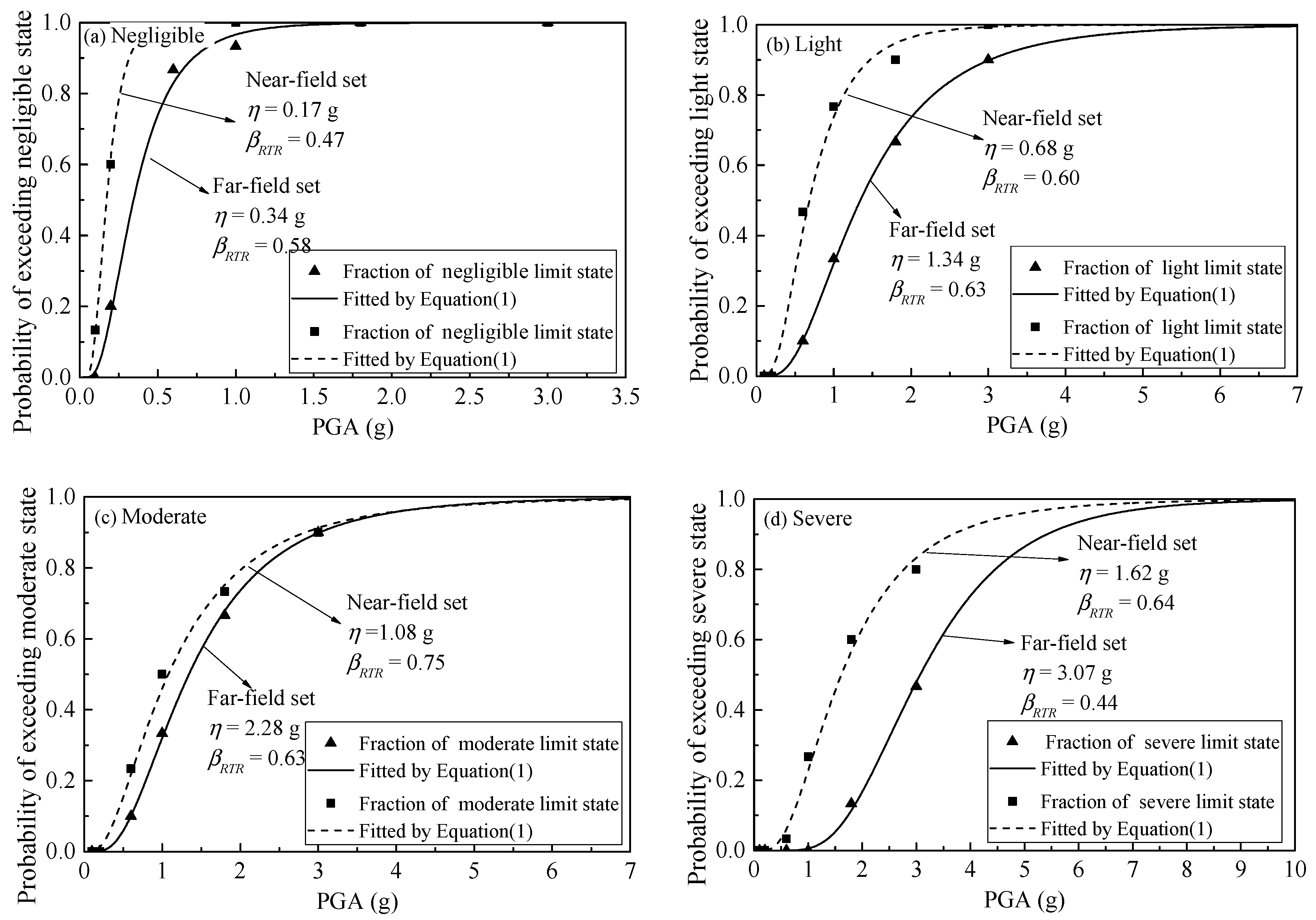
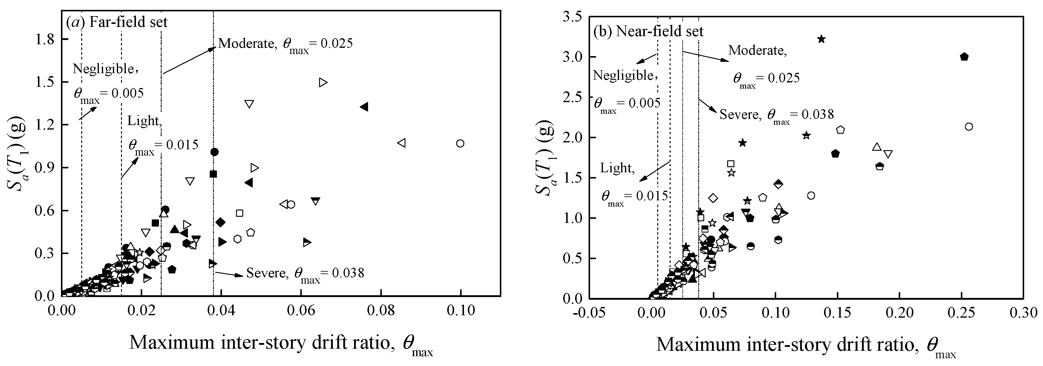
Figure 3 shows the θmax of the 48-story mega-scale frame structure under these six ground motion intensity levels of the two record sets. It can be seen from the figure that the structure reaches a larger θmax under the motivation of near-field records. The process of seismic fragility analysis is illustrated in Figure 4 for far-field and near-field earthquakes, respectively, in which the fragility curves are characterized by PGA. In the far-field set, the median capacity η from the negligible limit state to the severe limit state for the building is 0.34 g, 1.34 g, 2.28 g, and 3.07 g, respectively. In the near-field set, these values are reduced to 0.17 g, 0.68 g, 1.08 g, and 1.62 g, respectively. In addition, it is clearly seen in four figures that the lognormal standard deviation βRTR increases from the negligible limit state to the severe limit state and then decreases at the severe limit state for both near-field and far-field conditions.

4. Influence of IMs on the Estimation of Fragility Curves

4.1. Comparative Analysis between PGA and Sa(T1)

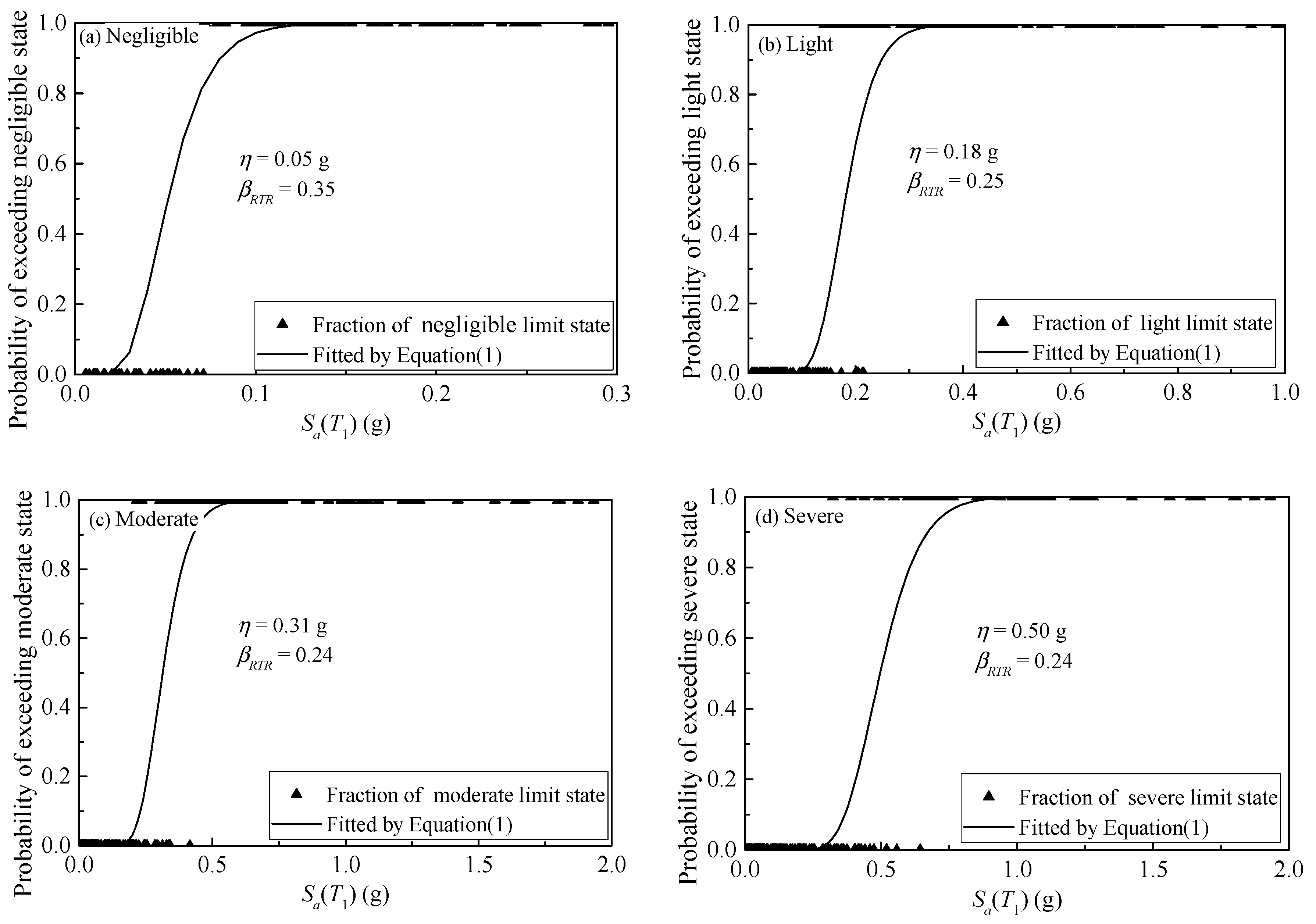
Ground motion intensity IMs have important effects on the results of probabilistic analysis based on seismic fragility; that is, they affect the correlation between seismic hazard intensity level and structural damage. Figure 4 shows that the discreteness represented by PGA is obviously high, and the βRTR value is approximately 0.6. Sa(T1) are used here for fragility comparative analysis with PGA. As shown in Figure 5, when the PGA is converted to Sa(T1), each record has a different seismic intensity level. Note that, to obtain the fragility curves using the MSA method, nj in Equation (1) is fixed to 1. When θmax is larger than the threshold of the corresponding limit state, the probability of exceeding the limit state is set to 1.
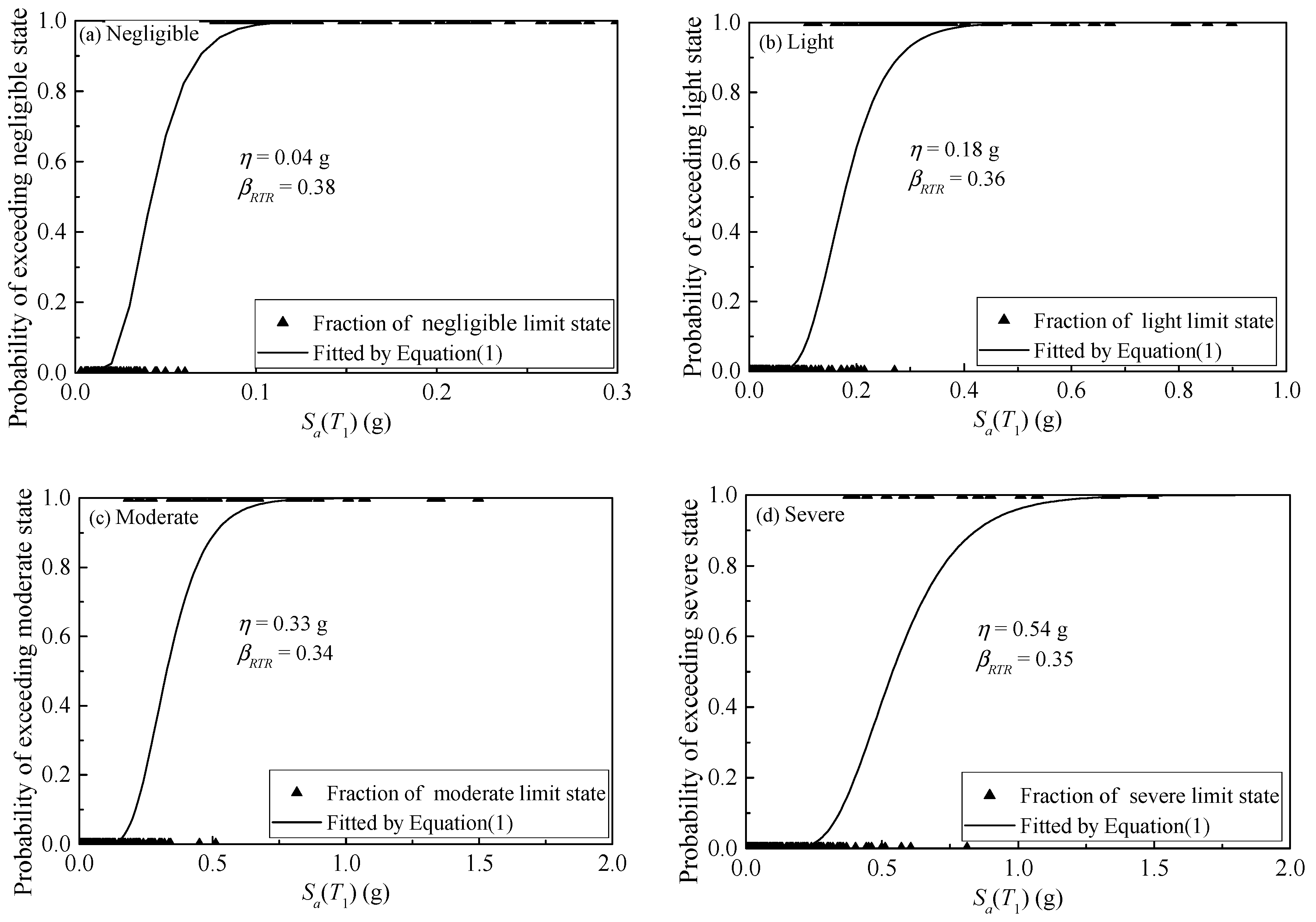
The fragility analysis results defined by Sa(T1) at these four limit states for both set earthquakes are presented in Figure 6 and Figure 7, respectively. The difference in the median capacity η obtained in these four limit states of the 48-story structure for both sets is not particularly large, while the use of Sa(T1) reduces the sensitivity of the structural damage to the ground motion characteristics compared to Figure 4. More importantly, the discreteness βRTR estimated by Sa(T1) under each limit state is approximately 0.3, which is much smaller than that estimated by PGA. Compared with the use of PGA, it can significantly reduce the dispersion βRTR between ground motions by up to 34%, 43%, 46%, and 20% from negligible to severe limit states, respectively, in the case of far-field earthquakes. In the near field, these reductions are 26%, 58%, 68%, and 63%, respectively.

4.2. Influence of Intensity Measures on the Estimation of βRTR

The 27 IMs selected in Table 3 are used here for comparative analysis. Figure 8 and Figure 9 illustrate the lognormal standard deviation βRTR estimated at each limit state under far-field and near-field earthquakes, respectively. Notably, Sa(T1) and its improved measures show thought-provoking performance characteristics. Sa(T1) exhibits better performance than PGA because Sa(T1) considers the dynamic properties of the structure and is more closely related to the structural characteristics. It can be clearly seen that the IMs considering the effect of the softened period (i.e., S*, IM-CR, IM-SR, INP, and SN1) are not better than the IMs considering the effect of higher modes (i.e., S a 12 * , S a 123 * , IM12, IM123, SN2, S12, S123, and S ¯ a ).
In addition, it can be observed that, among the four limit states, the ground motion IMs considering the softened period have the best performance in the severe limit state because the severe limit state has stronger structural nonlinearity, and the effect of the softened period is obvious. Most IMs considering higher mode shapes perform best in the negligible or light limit states among the four limit states in far-field earthquakes. This is because the nonlinearity of the structure is not strong at the negligible limit state, and the effect of the high-order mode shape is obvious. However, this result is not prominent in the near-field ground motion. Some higher-mode IMs, such as SN2, S12, and S123, perform best in the severe limit state instead, which may be related to the ground motion characteristics. The IM Sa,gm(Ti), which considers both the softened period effect and the higher mode effect, has excellent performance in both near-field and far-field earthquakes, and the performance is stable.
The number of combined terms and the combined power index have a significant impact on the flexibility of the combination-type IMs. Due to considering the three combination modes, the performance of IM123 and S ¯ a in the near-field earthquakes is worse than that of other IMs considering two modes, which is very different from the performance in the far-field earthquakes. Similarly, due to the difference in the combined power exponents, for example, IM12 corresponds to S12, and IM123 corresponds to S123, and their performances are quite different under different ground motions and limit states. In addition, due to the different softened periods considered in S* and SN1, the former is two times T1 and the latter is 1.5 times T1, and their estimated βRTR at different limit states are different.
Among the three magnitude-type ground motion IMs, PGV shows larger advantages over PGA and PGD. Similarly, the velocity-related IMs SMV and Sv(T1) are more superior than other IMs of the same type. However, the velocity-related IMs HI and VSI do not show low discreteness, especially in the near-field motion. This is because, compared with other velocity-type IMs, the spectral velocity integrals involved in HI and VSI focus on the 0.1 s to 2.5 s period. SMV and Sv(T1) focus on a single period closely related to structure. It is also due to the consideration of structural properties that Sv(T1) outperforms PGV. In addition, V/A exhibits lower dispersion in far-field vibrations. The acceleration-related IMs PGA, SMA, EDA, and ASI all have poor performance, with high discreteness, and their performance in these four damage limit states under the excitations of the two groups of records is not regular, showing strong sensitivity to ground motion characteristics. Displacement-related ground motion intensity measures PGD and Sd(T1) perform better than these acceleration-related IMs, especially Sd(T1) in the cases of far-field ground motions, showing that Sd(T1) has a stronger sensitivity to ground motion characteristics.

4.3. Optimal IM at Different Limit States

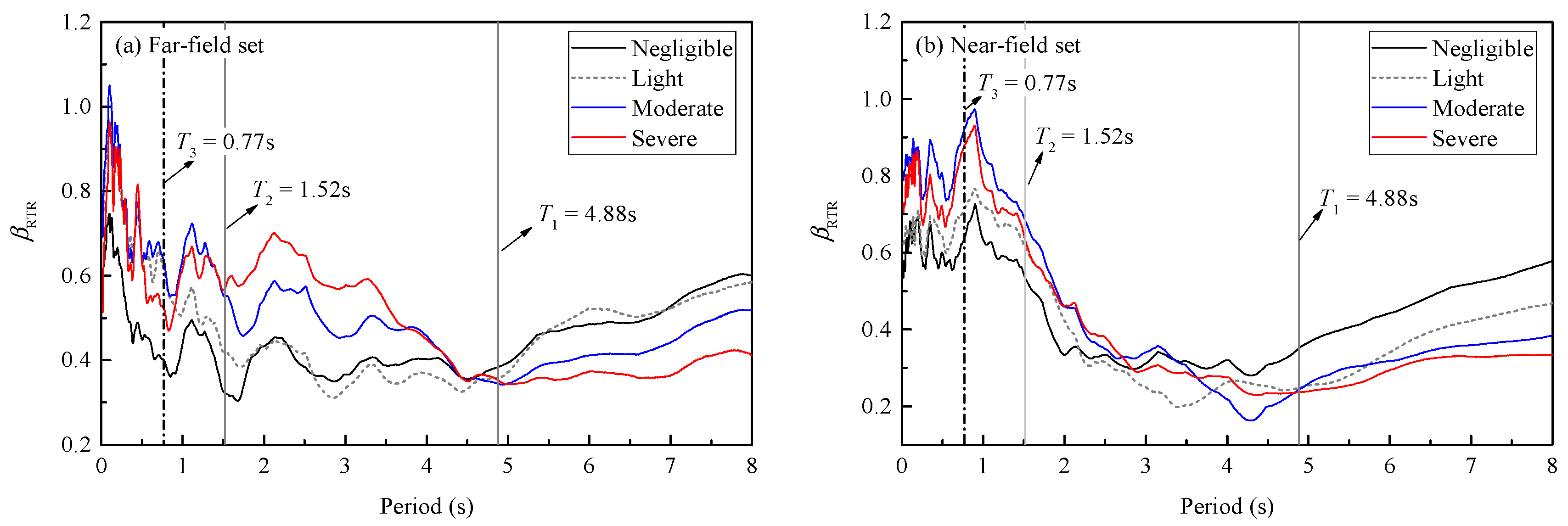
Combining the analysis results above, different types of ground motion IMs show their respective regularity in the two set ground motions, and there are certain differences in different damage limit states. It can be seen from the above analysis that the combination-type IMs based on Sa(T1) considering the effect of higher mode shape have better applicability in each limit state. Figure 10 shows the dispersion βmax of Sa(T1), IM12, IM123, S12, and S123 estimated at each limit state. Under far-field earthquakes, the estimated βRTR of the four improved IMs based on Sa(T1) are lower than those of Sa(T1) in each limit state. However, not all improved IMs are better than Sa(T1) in each limit state under near-field earthquakes. Obviously, this is related to the ground motion characteristics, the combination term and the combination power index of the improved measure.
Figure 11 shows the correlation between the spectral acceleration at an arbitrary period and the maximum drift ratio θmax, which is measured here by βRTR. It can be seen from the figure that there is a lower dispersion in the left part of the fundamental period T1, especially in the near-field earthquakes. This is why the combination-type intensity measures considering higher mode shapes can achieve lower dispersion in near-field earthquakes (see Figure 10). In addition, the discrete trends in each limit state are distinct. For the severe limit state, lower dispersion is obtained on the right of T1 and higher dispersion is obtained on the left side. For both negligible and light limit states, especially in far-field earthquakes, lower dispersion is obtained on the left side of T1 and higher dispersion is obtained on the right side. This may be because the softened period effect is more pronounced in the limit state with a higher damage degree, while the effect of the higher mode is more obvious in the limit state with a low damage degree.
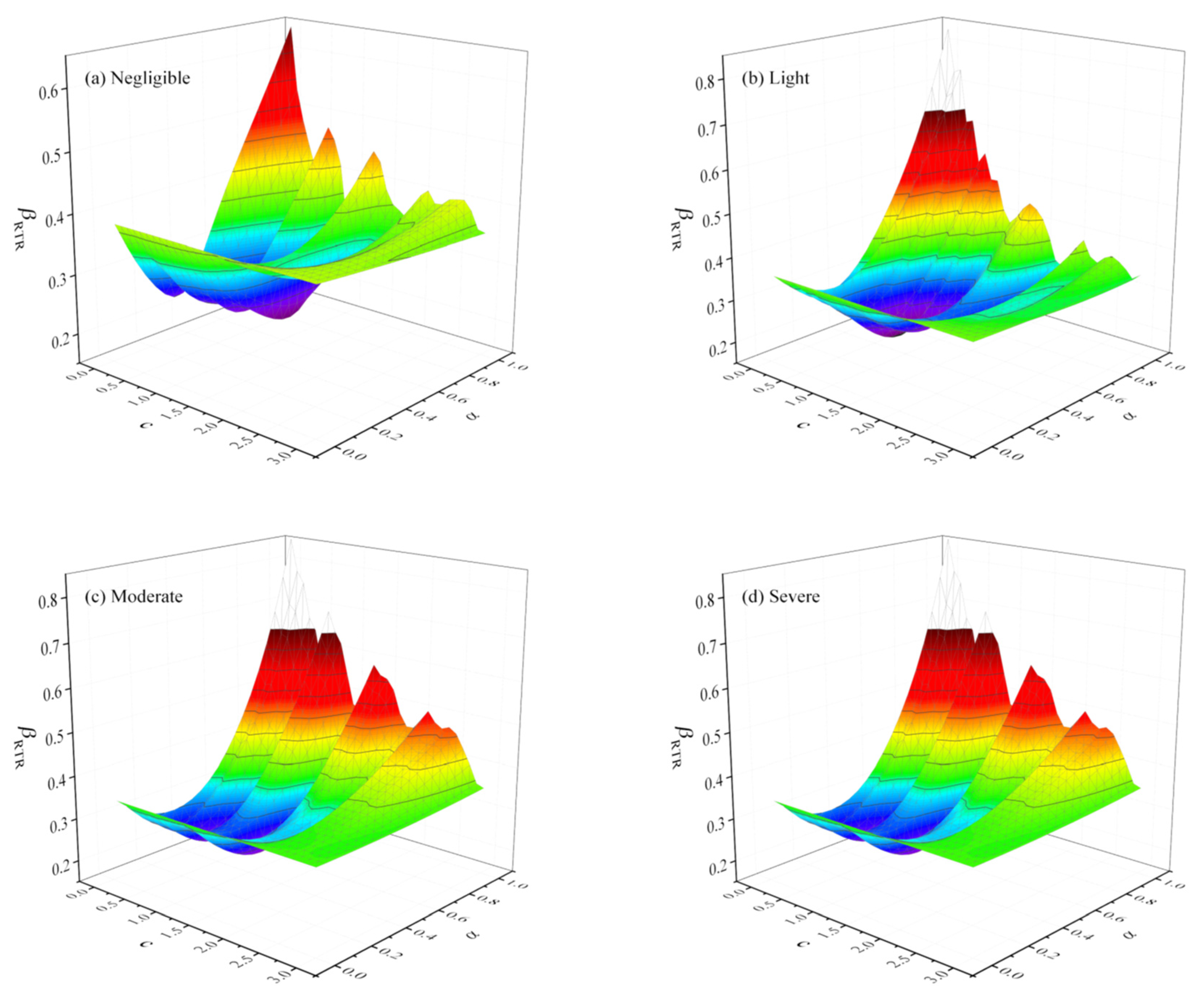
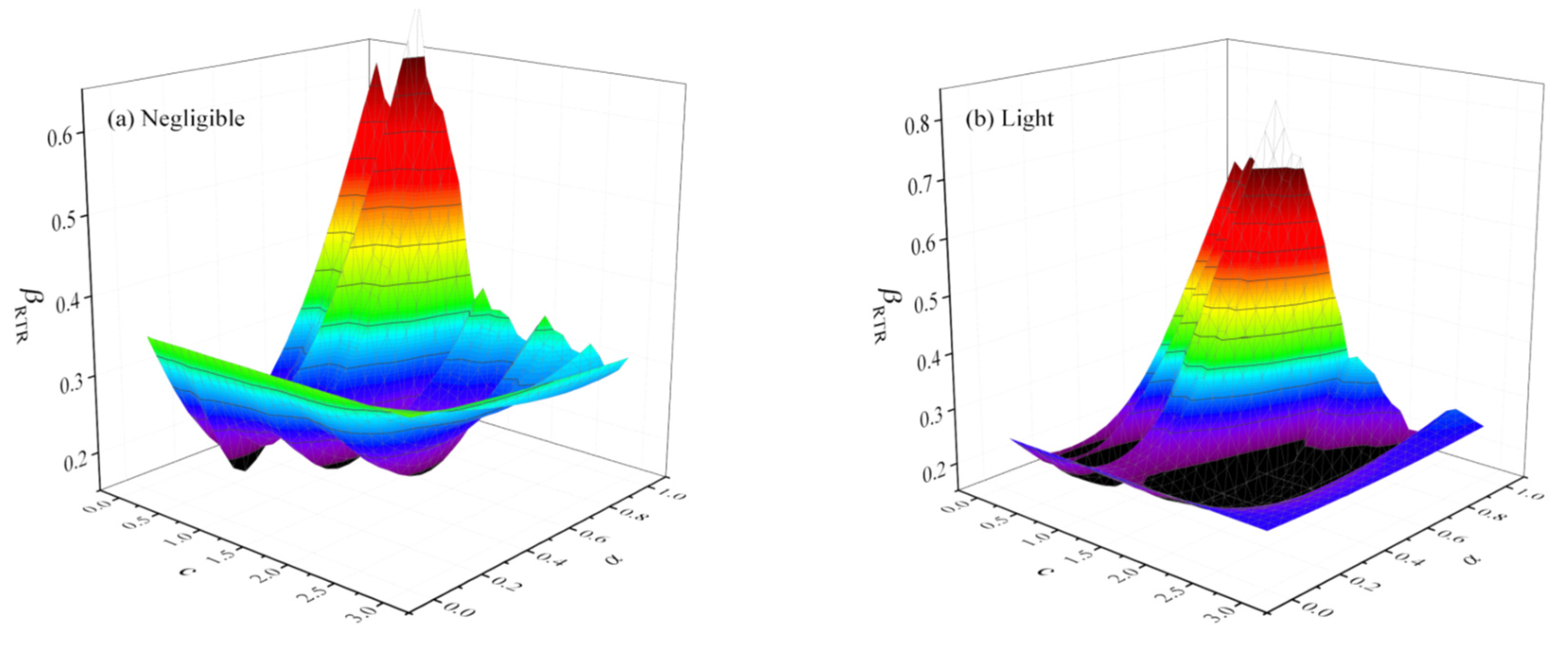
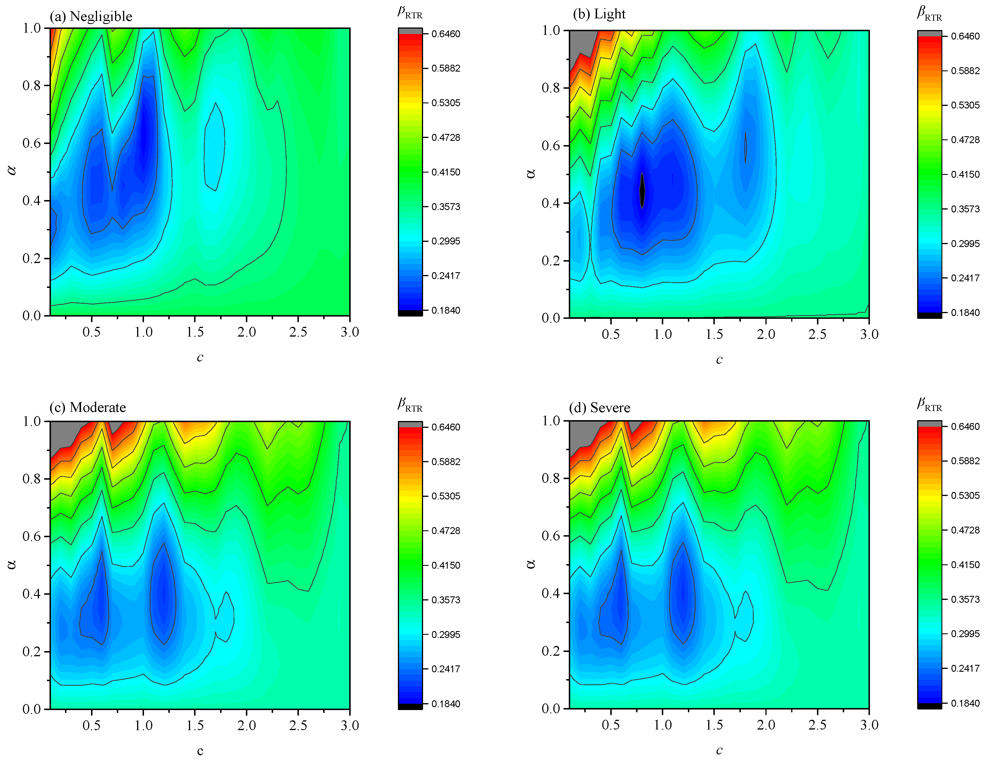
To obtain lower dispersion, the optimal combination term Sa(cT2) and power exponent α are obtained based on I M 12 * considering the two combination modes. Figure 12 and Figure 13 show the estimated discreteness βRTR using I M 12 * under different parameters c and α. It can be seen from the figures that the discreteness estimated by I M 12 * under different parameters varies greatly, and smaller βRTR values are produced in some areas. From the changing trend, both the far-field and near-field sets achieve the maximum discreteness βRTR when c is small and α is large. Under far-field vibration, when c is approximately 1 and α is approximately 0.4, a small βRTR is obtained. However, under the near-field vibration, the range of obtaining a small dispersion is very wide, especially at high levels of damage limit states, and it is not as concentrated as far-field.
I M 12 * = S a ( T 1 ) 1 α S a ( c T 2 ) α
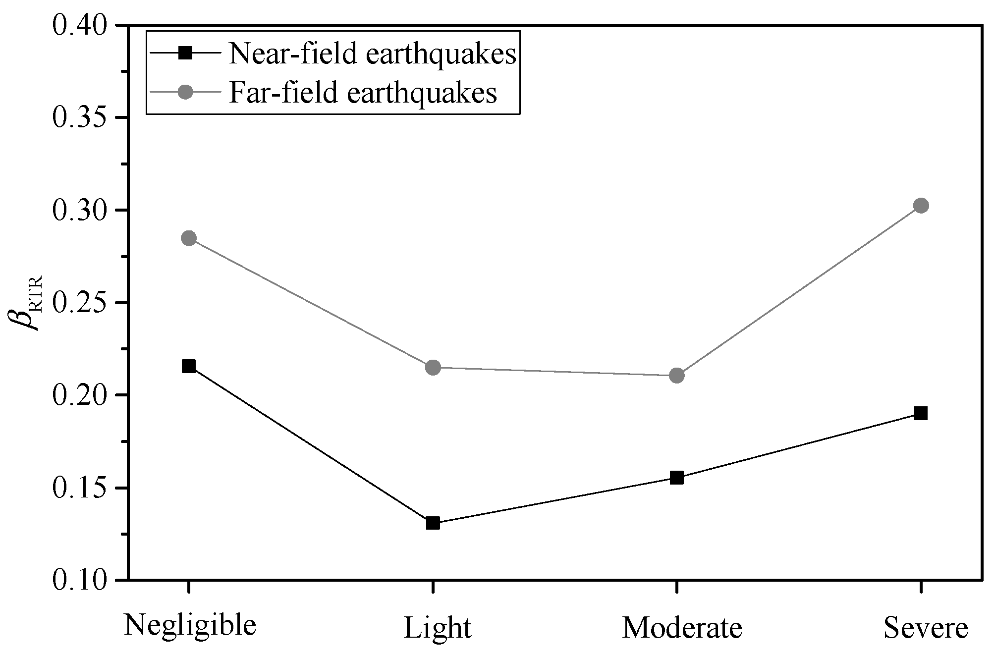
To clearly detect the change trend, the three-dimensional Figure 12 and Figure 13 are converted into two-dimensional figures, which are Figure 14 and Figure 15, respectively. Higher βRTR values are obtained in the upper left corner, accompanied by a smaller c and a larger α. Figure 14 illustrates that, for far-field earthquakes, it is recommended that I M 12 * take c as 1.2 and α as 0.4. For near-field earthquakes, it is better for c to be 1.4 in Figure 15. This may be due to the more destructive near-field earthquakes and the weakening of the effect of higher mode shapes. Figure 16 shows the estimated βRTR values for I M 12 * using the recommended parameters. Compared with Figure 10, lower dispersion and higher stability (i.e., closer values for each limit state) can be obtained by the proposed IM, especially under near-field earthquakes.

5. Conclusions

The flexibility of 27 ground motion IMs in the seismic fragility analysis of a 48-story super tall building under four different damage limit states excited by two sets of ground motions with different characteristics is investigated. The results show that the ground motion characteristics and damage limit states have nonnegligible effects on the flexibility of the ground motion intensity measures. Through in-depth analysis of the correlation between spectral acceleration and maximum interstory drift ratio, the combination-type intensity measure is optimized. The conclusions of the study are as follows:
(1)
Among these 27 IMs, those that are not closely related to structural dynamic parameters tend to perform poorly. For example, Sa(T1) exhibits better performance than PGA, and the velocity-related IMs SMV and Sv(T1) are superior to other IMs of the same type. However, for velocity-type IM PGV, even though they are not closely related to structural dynamic parameters, lower discreteness can still be obtained. For combination-type IMs, the number of combined terms and the combined power index have a significant impact on their performance.
(2)
The IMs considering the effect of the higher modes perform better than IMs considering the effect of the softened period. Among the four limit states, the ground motion IMs considering the softened period present the best performance in the severe limit state. Most ground motion IMs considering higher mode shapes perform best in the negligible or light limit states among the four limit states in far-field earthquakes.
(3)
The correlation between structural damage and spectral acceleration is affected by the damage limit state and ground motion characteristics. Based on this result, the combination-type ground motion intensity measure is improved, and different parameter values for near-field and far-field earthquakes are proposed. Perhaps, because of the weakening of the effect of higher mode shapes under near-field earthquakes, a larger value of c is adopted in near-field earthquakes.
Note that only one super high-rise building was used for analysis here, and the ground motion samples used were also limited, so the relevant conclusions have certain limitations.

Author Contributions

Conceptualization, Y.Z., R.S. and B.S.; Data curation, T.L., Y.S. and L.L.; Formal analysis, Y.Z. and Y.S.; Investigation, Y.Z. and T.L.; Methodology, T.L.; Project administration, Y.Z. and B.S.; Software, R.S. and Y.S.; Validation, Y.Z.; Visualization, L.L.; Writing—original draft, Y.Z., B.S., T.L. and Y.S.; Writing—review & editing, Y.Z., B.S. and Y.S. All authors have read and agreed to the published version of the manuscript.

Funding

This research was financially supported by the National Natural Science Foundation of China Youth Fund (52108133, 52108457), the Jiangsu Province Natural Science Foundation (BK20210371), the Natural Science Foundation of the Jiangsu Higher Education Institutions of China (20KJB560014), High-level Talent Research Fund of Nanjing Forestry University (163050115), the Fundamental Research Funds for the Central Universities (B210201019), the Opening Funds of State Key Laboratory of Building Safety and Built Environment & National Engineering Research Center of Building Technology (BSBE2021-12), Nanjing Forestry University Undergraduate Innovation Training Program (2021NFUSPITP0221, 2022NFUSPITP0128, and 2022NFUSPITP0124), and Jiangsu Undergraduate Innovation Training Program (202110298079Y and 202210298025Z).

Institutional Review Board Statement

Not applicable.

Informed Consent Statement

Not applicable.

Data Availability Statement

The raw data supporting the conclusions of this article will be made available by the authors without undue reservation.

Conflicts of Interest

The authors declare no conflict of interest.

References

  1. Fu, X.; Li, H.N.; Li, G.; Dong, Z.Q. Fragility analysis of a transmission tower under combined wind and rain loads. J. Wind Eng. Ind. Aerodyn. 2020, 199, 104098. [Google Scholar] [CrossRef]
  2. Dong, Z.Q.; Li, G.; Song, B.; Lu, G.H.; Li, H.N. Failure risk assessment method of masonry structures under earthquakes and flood scouring. Mech. Adv. Mater. Struct. 2022, 29, 3055–3066. [Google Scholar] [CrossRef]
  3. Aloisio, A.; Contento, A.; Alaggio, R.; Briseghella, B.; Fragiacomo, M. Probabilistic Assessment of a Light-Timber Frame Shear Wall with Variable Pinching under Repeated Earthquakes. J. Struct. Eng. 2022, 148, 04022178. [Google Scholar] [CrossRef]
  4. Huang, L.; Zhou, Z.; Wei, Y.; Xie, Q.; Sun, X. Seismic performance and resilience assessment of friction damped self-centering prestressed concrete frames. Eng. Struct. 2022, 263, 114346. [Google Scholar] [CrossRef]
  5. Huang, L.; Clayton, P.M.; Zhou, Z. Seismic design and performance of self-centering precast concrete frames with variable friction dampers. Eng. Struct. 2021, 245, 112863. [Google Scholar] [CrossRef]
  6. Zhang, Q.; Wei, Z.Y.; Gu, X.L.; Yang, Q.C.; Li, S.Y.; Zhao, Y.S. Confinement behavior and stress-strain response of square concrete columns strengthened with carbon textile reinforced concrete (CTRC) composites. Eng. Struct. 2022, 266, 114592. [Google Scholar] [CrossRef]
  7. Zhang, Q.; Zheng, N.H.; Gu, X.L.; Wei, Z.Y.; Zhang, Z. Study of the confinement performance and stress-strain response of RC columns with corroded stirrups. Eng. Struct. 2022, 266, 114476. [Google Scholar] [CrossRef]
  8. Sun, B.; Gu, Q.; Zhang, P.; Ou, J. A practical numerical substructure method for seismic nonlinear analysis of tall building structures. Struct. Des. Tall Spec. Build. 2017, 26, 1377. [Google Scholar] [CrossRef]
  9. Chen, X.; Xiang, N.; Guan, Z.; Li, J. Seismic vulnerability assessment of tall pier bridges under mainshock-aftershock-like earthquake sequences using vector-valued intensity measure. Eng. Struct. 2022, 253, 113732. [Google Scholar] [CrossRef]
  10. Chen, X.; Xiong, J. Seismic resilient design with base isolation device using friction pendulum bearing and viscous damper. Soil Dyn. Earthq. Eng. 2022, 153, 107073. [Google Scholar] [CrossRef]
  11. Chen, X.; Ikago, K.; Guan, Z.; Wang, X. Lead-Rubber-Bearing with Negative Stiffness Springs (LRB-NS) for Base-Isolation Seismic Design of Resilient Bridges: A Theoretical Feasibility Study. Eng. Struct. 2022, 266, 114601. [Google Scholar] [CrossRef]
  12. Wang, Y.; Zhou, Z.; Huang, L. Effects of loading rates on the hysteretic response of resilient variable friction dampers. Int. J. Steel Struct. 2021, 21, 1550–1563. [Google Scholar] [CrossRef]
  13. Sun, B.Y.; Zhang, Y.T.; Dai, D.H.; Wang, L.; Ou, J.P. Seismic fragility analysis of large-scale frame structures with local nonlinearities using an efficient reduced-order NR method. Soil Dyn. Earthq. Eng. 2022; accepted. [Google Scholar]
  14. Lai, X.; He, Z.; Chen, Y.; Zhang, Y.; Li, Z.; Guo, Z.; Ma, L. A modified spectral-velocity-based earthquake intensity measure for super high-rise buildings. Soil Dyn. Earthq. Eng. 2022, 162, 107504. [Google Scholar] [CrossRef]
  15. Riddell, R. On ground motion intensity indices. Earthq. Spectra 2007, 23, 147–173. [Google Scholar] [CrossRef]
  16. Ye, L.P.; Ma, Q.L.; Miao, Z.W.; Guan, H.; Zhuge, Y. Numerical and comparative study of earthquake intensity indices in seismic analysis. Struct. Design Tall Spec. Build. 2013, 22, 362–381. [Google Scholar] [CrossRef]
  17. Kostinakis, K.; Fontara, I.K.; Athanatopoulou, A.M. Scalar structure-specific ground motion intensity measures for assessing the seismic performance of structures: A review. J. Earthq. Eng. 2018, 22, 630–665. [Google Scholar] [CrossRef]
  18. Zhang, Y.T.; He, Z.; Yang, Y.F. A spectral-velocity-based combination-type earthquake intensity measure for super high-rise buildings. Bull. Earthq. Eng. 2018, 16, 643–677. [Google Scholar] [CrossRef]
  19. Zhang, Y.T.; He, Z.; Lu, W.; Yang, Y. A spectral-acceleration-based linear combination-type earthquake intensity measure for high-rise buildings. J. Earthq. Eng. 2018, 22, 1479–1508. [Google Scholar] [CrossRef]
  20. Zhang, Y.T.; He, Z. Appropriate ground motion intensity measures for estimating the earthquake demand of floor acceleration-sensitive elements in super high-rise buildings. Struct. Infrastruct. Eng. 2019, 15, 467–483. [Google Scholar] [CrossRef]
  21. Lu, X.; Lu, X.; Guan, H.; Ye, L. Comparison and selection of ground motion intensity measures for seismic design of super high-rise buildings. Adv. Struct. Eng. 2013, 16, 1249–1262. [Google Scholar] [CrossRef] [Green Version]
  22. Ouyang, X.Y.; Zhang, Y.T.; Ou, X.Y.; Shi, Y.A.; Liu, S.Y.; Fan, J.X. Seismic fragility analysis of buckling-restrained brace-strengthened reinforced concrete frames using a performance-based plastic design method. Structures 2022, 43, 338–350. [Google Scholar] [CrossRef]
  23. Zhang, Y.T.; Ouyang, X.Y.; Sun, B.Y.; Shi, Y.A.; Wang, Z. A comparative study on seismic fragility analysis of RC frame structures with consideration of modeling uncertainty under far-field and near-field ground motion excitation. Bull. Earthq. Eng. 2022, 20, 1455–1487. [Google Scholar] [CrossRef]
  24. Baker, J.W. Efficient analytical fragility function fitting using dynamic structural analysis. Earthq. Spectra 2015, 31, 579–599. [Google Scholar] [CrossRef]
  25. Vamvatsikos, D.; Cornell, C.A. Incremental dynamic analysis. Earthq. Eng. Struct. Dyn. 2002, 31, 491–514. [Google Scholar] [CrossRef]
  26. GB50011-2010; Code for Seismic Design of Buildings. China Architecture & Building Press: Beijing, China, 2010. (In Chinese)
  27. Sun, B.; Zhang, Y.; Huang, C. Machine learning-based seismic fragility analysis of large-scale steel buckling restrained brace frames. CMES-Comput. Model. Eng. Sci. 2020, 125, 755–776. [Google Scholar] [CrossRef]
  28. Mazzoni, S.; McKenna, F.; Scott, M.H.; Fenves, G.L. Open System for Earthquake Engineering Simulation (OpenSees) Command Language Manual. Available online: http://opensees.berkeley.edu/wiki/index.php/Command_Manual (accessed on 2 March 2011).
  29. Zhu, M.; McKenna, F.; Scott, M.H. OpenSeesPy: Python library for the OpenSees finite element framework. SoftwareX 2018, 7, 6–11. [Google Scholar] [CrossRef]
  30. Ancheta, T.D.; Darragh, R.B.; Stewart, J.P.; Seyhan, E.; Silva, W.J.; Chiou, B.S.J.; Wooddell, K.E.; Graves, R.W.; Kottke, A.R.; Boore, D.M.; et al. NGA-West2 database. Earthq. Spectra 2014, 30, 989–1005. [Google Scholar] [CrossRef]
  31. Baker, J.W. Quantitative classification of near-fault ground motions using wavelet analysis. Bull. Seismol. Soc. Am. 2007, 97, 1486–1501. [Google Scholar] [CrossRef]
  32. Quantification of Building Seismic Performance Factors; FEMA P695; FEMA: Washington, DC, USA, 2009.
  33. Sucuoǧlu, H.; Nurtuǧ, A. Earthquake ground motion characteristics and seismic energy dissipation. Earthq. Eng. Struct. Dyn. 1995, 24, 1195–1213. [Google Scholar] [CrossRef]
  34. Nuttli, O.W. The Relation of Sustained Maximum Ground Acceleration and Velocity to Earthquake Intensity and Magnitude; Miscellaneous Paper S-71-1, Report 16; U.S. Army Corps of Engineers, Waterways Experiment Station: Vicksburg, MS, USA, 1979.
  35. Benjamin, J.R.; Associates, Inc. A Criterion for Determining Exceedances of the Operating Basis Earthquake; EPRI Report NP-5930; Electric Power Research Institute: Palo Alto, CA, USA, 1988. [Google Scholar]
  36. Housner, G.W. Spectrum Intensity of Strong Motion Earthquakes. In Proceedings of the Symposium on Earthquakes and Blast Effects on Structures, Los Angeles, CA, USA, 21 June 1952. [Google Scholar]
  37. Von Thun, J.L.; Roehm, L.H.; Scott, G.A.; Wilson, J. Earthquake Ground Motions for Design and Analysis of Dams. In Earthquake Engineering and Soil Dynamics II; Recent Advances in Ground-Motion Evaluation; ASCE Library: Reston, VA, USA, 1988; pp. 463–481. [Google Scholar]
  38. Shome, N.; Cornell, C.A. Probabilistic Seismic Demand Analysis of Non-Linear Structures (Report No. RMS-35); Stanford University: Stanford, CA, USA, 1999. [Google Scholar]
  39. Vamvatsikos, D.; Cornell, C.A. Developing efficient scalar and vector intensity measures for IDA capacity estimation by incorporating elastic spectral shape information. Earthq. Eng. Struct. Dyn. 2005, 34, 1573–1600. [Google Scholar] [CrossRef]
  40. Zhou, Y.; Su, N.; Lu, X. Study on intensity measure of incremental dynamic analysis for high-rise structures. J. Build. Struct. 2013, 34, 53–60. (In Chinese) [Google Scholar]
  41. Lu, X.; Ye, L.; Lu, X.; Li, M.; Ma, X. An improved ground motion intensity measure for super high-rise buildings. Sci. China Technol. Sci. 2013, 56, 1525–1533. [Google Scholar] [CrossRef]
  42. Lin, L.; Naumoski, N.; Saatcioglu, M.; Foo, S. Improved intensity measures for probabilistic seismic demand analysis. Part 1: Development of improved intensity measures. Can. J. Civ. Eng. 2011, 38, 79–88. [Google Scholar] [CrossRef]
  43. Cordova, P.P.; Deierlein, G.G.; Mehanny, S.S.; Cornell, C.A. Development of a two-parameter seismic intensity measure and probabilistic assessment procedure. In Proceedings of the Second US–Japan Workshop on Performance-Based Earthquake Engineering Methodology for Reinforced Concrete Building Structures, Sapporo, Hokkaido, 11–13 September 2001; pp. 187–206. [Google Scholar]
  44. Mehanny, S.S. A broad-range power-law form scalar-based seismic intensity measure. Eng. Struct. 2009, 31, 1354–1368. [Google Scholar] [CrossRef]
  45. Bojórquez, E.; Iervolino, I. Spectral shape proxies and nonlinear structural response. Soil Dyn. Earthq. Eng. 2011, 31, 996–1008. [Google Scholar] [CrossRef]
  46. Kazantzi, A.K.; Vamvatsikos, D. Intensity measure selection for vulnerability studies of building classes. Earthq. Eng. Struct. Dyn. 2015, 44, 2677–2694. [Google Scholar] [CrossRef]
  47. Zhang, Y.T.; He, Z. Seismic collapse risk assessment of super high-rise buildings considering modeling uncertainty: A case study. Struct. Des. Tall Spec. Build. 2020, 29, e1687. [Google Scholar] [CrossRef]
  48. Zentner, I.; Gündel, M.; Bonfils, N. Fragility analysis methods: Review of existing approaches and application. Nucl. Eng. Des. 2017, 323, 245–258. [Google Scholar] [CrossRef]
  49. Shinozuka, M.; Feng, M.Q.; Lee, J.; Naganuma, T. Statistical analysis of fragility curves. J. Eng. Mech. ASCE 2000, 126, 1224–1231. [Google Scholar] [CrossRef]
  50. Güneyisi, E.M. Seismic reliability of steel moment resisting framed buildings retrofitted with buckling restrained braces. Earthq. Eng. Struct. Dyn. 2012, 41, 853–874. [Google Scholar] [CrossRef]
  51. Eads, L.; Miranda, E.; Krawinkler, H.; Lignos, D.G. An efficient method for estimating the collapse risk of structures in seismic regions. Earthq. Eng. Struct. Dyn. 2013, 42, 25–41. [Google Scholar] [CrossRef]
Figure 1. Elevation and plan views of the 48-story building.
Buildings 12 01530 g001
Figure 2. Information on the source-to-site distance and moment magnitude for both sets.
Buildings 12 01530 g002
Figure 3. Maximum interstory drift ratios θmax obtained at six IM levels in both record sets.
Buildings 12 01530 g003
Figure 4. Fragility curves characterized by PGA for the four damage limit states in cases of far-field and near-field sets.
Buildings 12 01530 g004
Figure 5. Discrete points θmax-Sa(T1) for both record sets.
Buildings 12 01530 g005
Figure 6. Fragility curves characterized by Sa(T1) for the four damage limit states in cases of far-field set.
Buildings 12 01530 g006
Figure 7. Fragility curves characterized by Sa(T1) for the four damage limit states in cases of near-field set.
Buildings 12 01530 g007
Figure 8. βRTR estimated at different limit states under far-field ground motions.
Buildings 12 01530 g008
Figure 9. βRTR estimated at different limit states under near-field ground motions.
Buildings 12 01530 g009
Figure 10. βRTR estimated by Sa(T1), IM12, IM123, S12, and S123 at different limit states.
Buildings 12 01530 g010
Figure 11. Dispersion between θmax and spectral acceleration corresponding to arbitrary periods.
Buildings 12 01530 g011
Figure 12. βRTR obtained using I M 12 * with different values of c and α under far-field earthquakes.
Buildings 12 01530 g012
Figure 13. βRTR obtained using I M 12 * with different values of c and α under near-field earthquakes.
Buildings 12 01530 g013aBuildings 12 01530 g013b
Figure 14. βRTR obtained using I M 12 * under far-field earthquakes.
Buildings 12 01530 g014
Figure 15. βRTR obtained using I M 12 * under near-field earthquakes.
Buildings 12 01530 g015
Figure 16. βRTR obtained using I M 12 * that uses the recommended parameters.
Buildings 12 01530 g016
Table 1. Section geometries and materials of structural components (units: m).
ComponentFloorSectionSection GeometryMaterial
Mega column1–12box-type0.9 × 0.9 × 0.065 × 0.065Q345
13–24box-type0.9 × 0.9 × 0.04 × 0.04Q345
25–36box-type0.8 × 0.8 × 0.04 × 0.04Q235
37–48box-type0.7 × 0.7 × 0.03 × 0.03Q235
Secondary column1–24box-type0.8 × 0.8 × 0.06 × 0.06Q345
25–48box-type0.75 × 0.75 × 0.05 × 0.05Q235
Mega beam1–48I-type0.8 × 0.3 × 0.019 × 0.035Q235
Secondary beam1–48I-type0.692 × 0.3 × 0.013 × 0.02Q235
Mega-column beam1–48I-type0.7 × 0.3 × 0.013 × 0.024Q235
Mega-column brace1–24box-type0.25 × 0.25 × 0.018 × 0.018Q235
25–48box-type0.25 × 0.25 × 0.014 × 0.014Q235
Mega-beam brace19–20box-type0.35 × 0.35 × 0.02 × 0.02Q235
36–37, 48box-type0.35 × 0.35 × 0.018 × 0.018Q235
Slab1–48/40 × 40 × 0.12C30
Table 2. First five periods of the mega-scale frame structure.
Order12345
Period (s)T1 = 4.88T2 = 1.52T3 = 0.77T4 = 0.50T5 = 0.36
Table 3. Selected ground motions.
No.Far-Field SetNear-Field Set
YearEarthquakeFile NamesLowest
Frequency (Hz)
YearEarthquakeFile NamesLowest
Frequency (Hz)
11971San FernandoSFERN/PEL0900.11971SanFernandoSFERN/PUL1640.0875
21979Imperial Valley-06IMPVALL.H/H-DLT2620.08751979ImperialValley-06IMPVALL.H/H-EMO0000.1
31979Imperial Valley-06IMPVALL.H/H-E111400.11979ImperialValley-06IMPVALL.H/H-E041400.0625
41984Morgan HillMORGAN/G030900.11979ImperialValley-06IMPVALL.H/H-E061400.0625
51987Superstition Hills-02SUPER.B/B-ICC0000.08751979ImperialValley-06IMPVALL.H/H-E071400.075
61987Superstition Hills-02SUPER.B/B-IVW3600.11992CapeMendocinoCAPEMEND/PET0000.07
71989Loma PrietaLOMAP/A020430.0751994Northridge-01NORTHR/RRS2280.1
81989Loma PrietaLOMAP/AND2500.11995Kobe/JapanKOBE/KJM0000.0625
91989Loma PrietaLOMAP/OHW0000.11999Kocaeli/TurkeyKOCAELI/YPT0600.0875
101989Loma PrietaLOMAP/SFO0000.0751999Chi-Chi/TaiwanCHICHI/TCU052-E0.05
111992LandersLANDERS/CLW-LN0.11999Chi-Chi/TaiwanCHICHI/TCU065-E0.075
121992LandersLANDERS/YER2700.071999Chi-Chi/TaiwanCHICHI/TCU068-E0.0375
131995Kobe/JapanKOBE/ABN0900.0251999Chi-Chi/TaiwanCHICHI/TCU101-E0.05
141995Kobe/JapanKOBE/FKS0900.11999Chi-Chi/TaiwanCHICHI/TCU102-E0.0625
151999Kocaeli/TurkeyKOCAELI/ARE0000.08751999Duzce/TurkeyDUZCE/DZC1800.1
161999Kocaeli/TurkeyKOCAELI/DZC1800.11989LomaPrietaLOMAP/LEX0000.1
171999Chi-ChiCHICHI/CHY101-E0.052003Bam/IranBAM/BAM-L0.0625
181999Chi-ChiCHICHI/TCU045-E0.052010Darfield/NewZealandDARFIELD/GDLCN55W0.0625
191999Duzce/TurkeyDUZCE/BOL0000.06252010Darfield/NewZealandDARFIELD/LINCN23E0.075
201999Hector MineHECTOR/HEC0000.03752010Darfield/NewZealandDARFIELD/TPLCN27W0.0625
211989Loma PrietaLOMAP/WAH0000.11979ImperialValley-06IMPVALL.H/H-ECC002.AT20.075
221994Northridge-01NORTHR/TAR3600.11979ImperialValley-06IMPVALL.H/H-E10050.AT20.075
231999Chi-ChiCHICHI/TCU088-E0.11979ImperialValley-06IMPVALL.H/H-E05140.AT20.05
241999Chi-ChiCHICHI/TCU095-E0.051979ImperialValley-06IMPVALL.H/H-EDA270.AT20.02875
252004Niigata/JapanNIIGATA/NIG023EW0.0751979ImperialValley-06IMPVALL.H/H-HVP225.AT20.075
262007Chuetsu-oki/JapanCHUETSU/65005EW0.0751992LandersLANDERS/LCN260.AT20
272007Chuetsu-oki/JapanCHUETSU/65025EW0.06251999Chi-Chi_TaiwanCHICHI/CHY024-E.AT20.025
282007Chuetsu-oki/JapanCHUETSU/65056EW0.0751999Chi-Chi_TaiwanCHICHI/TCU049-E.AT20.025
292007Chuetsu-oki/JapanCHUETSU/65057EW0.11999Chi-Chi_TaiwanCHICHI/TCU075-E.AT20.05
302007Chuetsu-oki/JapanCHUETSU/6CB51EW0.11999Chi-Chi_TaiwanCHICHI/TCU082-E.AT20.05
Table 5. Criteria for four damage limit states.
Damage Limit Stateθmax
Negligible0.5%
Light1.5%
Moderate2.5%
Severe3.8%
Publisher’s Note: MDPI stays neutral with regard to jurisdictional claims in published maps and institutional affiliations.