Article

Semi-Transparent Water-Based Trombe Walls for Passive Air and Water Heating

Department of Mechanical Engineering, Lassonde School of Engineering, York University, Toronto, ON M3J 1P3, Canada
*
Author to whom correspondence should be addressed.
Buildings 2022, 12(10), 1632; https://doi.org/10.3390/buildings12101632
Submission received: 13 August 2022 / Revised: 1 October 2022 / Accepted: 5 October 2022 / Published: 8 October 2022
(This article belongs to the Special Issue Building Energy Retrofit for Sustainable Urban Renewal)

Abstract

:
Trombe walls provide a passive source of heating and ventilation for buildings. However, Trombe walls can also cause overheating during hot and sunny weather conditions. In this work, we investigate the potential of a multifunctional Trombe wall design, comprising a tinted acrylic sheet submerged in a water wall that functions as a thermal storage medium. The tinted acrylic sheet absorbs incident light, which is then converted to heat and absorbed by the water. The proposed Trombe wall can function as a tinted semi-transparent window to add aesthetic value. Furthermore, heated water rises to the top of the Trombe wall where it can be removed, which provides the dual benefit of preventing overheating and providing a source of preheated water for applications within the building. Experimental results performed on a laboratory-scale Trombe wall prototype showed that the percentage of solar-simulated light energy incident onto the Trombe wall prototype, over a period of five hours, that was stored as thermal energy in the water increased from 60.3% to 83.2% when tinted glass was inserted in the water storage wall. Furthermore, the temperature of the water at the top of the Trombe wall reached ~56 °C, which is suitable to be used as pre-heated water in building applications.

1. Introduction

It is important to integrate renewable energy into the building sector to the greatest extent possible because it accounts for 30% of the global energy consumption. Furthermore, more than half of the energy used in buildings is for space and water heating, and buildings can require more than 500 kWh per square meter of floor space annually. Moreover, going forward, it will be challenging for energy infrastructures to keep up with, and continue to provide for, increasing urban energy densities [1,2,3,4,5]. Trombe walls are a passive solar energy technology with high potential for reducing building energy loads because they are simple to build, easy to maintain, have very little operational costs, are highly efficient, and cost-effective. Indeed, it has been reported that a Trombe wall can reduce a building’s heating demands by 30% [6,7,8]. The classic Trombe wall consists of an air channel situated between a thermal storage wall and a glazed window. Sunlight passes through the glazed window and heats up the storage wall, which, in turn, heats up the air in the channel. Building air moves from indoors to the channel through a vent at the bottom of the thermal storage wall and is heated as it moves up the channel. Heated air returns to the building through a vent at the top of the thermal storage wall. The vents can be closed to prevent overheating, which is not uncommon when Trombe walls are operating in hot weather under sunny conditions. The thermal storage wall is typically made of high thermal capacity materials, such as bricks, concrete, and stone. The surface of the wall is usually painted black to increase the absorption of solar radiation.
Researchers have investigated the benefits of using different materials for Trombe walls. For example, numerous studies have investigated the performance of Trombe walls wherein the thermal storage wall comprises a Phase Change Material (PCM) [9]. PCMs can store solar thermal energy in the form of latent heat, which makes them a high-performance lightweight alternative to heavy Trombe walls. Sun et al. showed that indoor air temperature fluctuations during winter can be reduced by integrating paraffin-based PCMs with a phase temperature and latent heat of 19.45 °C, and 128.46 J/g, respectively [10]. Furthermore, Li et al. numerically investigated a Trombe wall with a thermal storage wall made of encapsulated PCMs (with a melting temperature of 27.5 °C and latent heat of 127 kJ/kg). Simulations were performed to study the performance of Trombe walls with and without PCMs. The results showed that using the Trombe wall with PCMs allowed for ~20% increase in the indoor temperature at night, as compared to the case when the Trombe wall without PCMs was used [11].
Trombe walls provide effective passive heating during the winter. However, they can also cause overheating during the summer months. Pittaluga performed a numerical analysis to study the performance of Trombe walls with an electrochromic glazing (EG). The transmittance of an EG can be reduced during summer months to prevent overheating. Numerical analysis revealed that the Trombe wall equipped with an EG provided an energy saving of about 17% [12]. Another way to reduce overheating from Trombe walls during summer weather conditions is to use water as the thermal storage medium. Water has a high heat capacity and can store more thermal energy than other thermal storage walls on a per volume basis. The high heat capacity also keeps the temperature of the water Trombe wall lower than other Trombe walls, which can help reduce thermal losses to the surroundings. Additionally, the water can potentially be removed from the Trombe wall and used as a source of hot water for the building. The ability to remove hot water from the Trombe wall during summer months is especially attractive for preventing overheating during hot weather conditions. Furthermore, the transparent property of water can be utilized in making aesthetically pleasing designs when architecting buildings. Indeed, translucent materials of different colors have been integrated into water Trombe walls, giving them a vibrant appearance [13]. Despite their unique combination of advantages, a limited amount of research has been done on water Trombe walls in comparison to other Trombe walls.
Weiliang et al. analyzed the thermal performance of a Trombe wall consisting of water as a thermal energy storage medium. A south-facing water Trombe wall prototype with a single-story house with floor area of 700 m2 and shape coefficient 0.374 (which is the ratio of the external surface area and inner volume) was set up in North China for experimental analysis, and a simulation model was set up in TRNSYS. The outer layer of the Trombe wall was made of a steel plate. A total of 29 small modules of water (with dimensions of 1.1 m × 0.4 m × 2.5 m) were placed along the inner side of the wall. Numerical and experimental analyses were conducted and compared with the traditional Trombe wall. The results showed a reduction in energy consumption per year by 8.6% and the indoor thermal comfort evaluation index was improved by approximately 13%, as compared to the classic Trombe wall [14]. Nayak did a numerical analysis of the thermal performance between a south-facing drum water wall and a water transwall. The drum wall consisted of metallic containers of water stacked upon each other. One surface of the wall was colored black and had glazing on it, but the other surface could be separated from the room by a concrete wall or insulating layer. The transwall consisted of water in containers that were made of parallel glass walls. Each wall had a semi-transparent material kept between the water column and the room, between the glazing and the water column, or in the water column itself. The results showed that the transwall met the daytime heating load more effectively than the drum wall, whereas the drum wall performed better in terms of load levelling and day–night performance [15]. Turner et al. studied the performance of a water Trombe wall consisting of 7.6 cm diameter plastic tubes embedded into a studded wall. During the winter season, the system was charged for 6 h with hot ambient air and then passively discharged for 18 h. The results showed that the Trombe wall temperature remained approximately 2.6 °C higher, even after the discharging cycle completed, which helped in reducing the heating load of the house. Further, it was noted that during the summer season, water walls can be charged using cool ambient air at night to achieve thermal comfort during the daytime [16]. Tiwari et al. did a comparative study of the total heat gain of different south facing Trombe walls, such as a glass wall, a water wall, an active air collector wall, and a transwall. Several design parameters were taken into consideration, such as the thickness of the water wall and transwall, and the flow rate of the air collector wall. The design parameters were varied for a heated room under winter weather conditions to conduct different experiments. The results showed that the performance of the water wall and the transwall were better for space heating during nighttime because of their greater thermal storage capacity. On the other hand, the glass wall and the air collector wall were efficient for space heating during sunshine hours. It was also observed that the air temperature of the room was higher during the extreme winter conditions in Srinagar, India, when a transwall was used in a non-conditioned passive solar house in comparison to when a water wall was used [17]. Mohamad et al. designed a novel Trombe wall to reduce the heating and cooling loads in the winter and summer seasons, respectively. The Trombe wall consisted of a water tank that acted as a thermal energy storage medium and could also supply hot water if required. The proposed Trombe wall model could be used for space heating during day and night, and excess heat could be used for domestic hot water supply in the summer season. The excess heat could be extracted out of the building through vents or could be used for domestic water heating purposes to reduce the cooling load. Their numerical results showed that the proposed system was more efficient in charging and discharging thermal energy, as compared to a classical Trombe wall. The thermal storage efficiency of the proposed system reached ~80% [18].
In this work we conducted experiments to investigate if water-based Trombe walls can be designed to provide multiple functions including the following: (1) to provide a passive source of heating, (2) to function as a window or tinted semi-transparent window, and (3) to provide heated water. Semi-transparent Trombe walls that can provide heated water for building applications have yet to be reported in the literature. We experimentally measured the thermal performance of a laboratory-scale Trombe wall prototype consisting of a tinted acrylic sheet integrated into a water storage wall. Specifically, a tinted acrylic sheet was integrated into the water wall, such that it was semi-transparent, which is desirable for the design of aesthetically pleasing Trombe walls. The Trombe wall design proposed in this work can provide passive heating throughout the year, and heated water during the summer months. Results from the experiments conducted in this work showed that the percentage of solar-simulated light energy incident onto the Trombe wall prototype for five hours, that was stored as thermal energy in the water, increased from 60.3% to 83.2% when tinted glass was inserted in the water storage wall. Furthermore, the temperature of the water at the top of the Trombe wall reached ~56 °C, which is suitable to be used as pre-heated water in building applications.

2. Materials and Methods

In previous work, we built a small Trombe wall prototype to study the effects of managing the airflow through Trombe wall vents on the amount of thermal energy stored in the thermal storage wall [
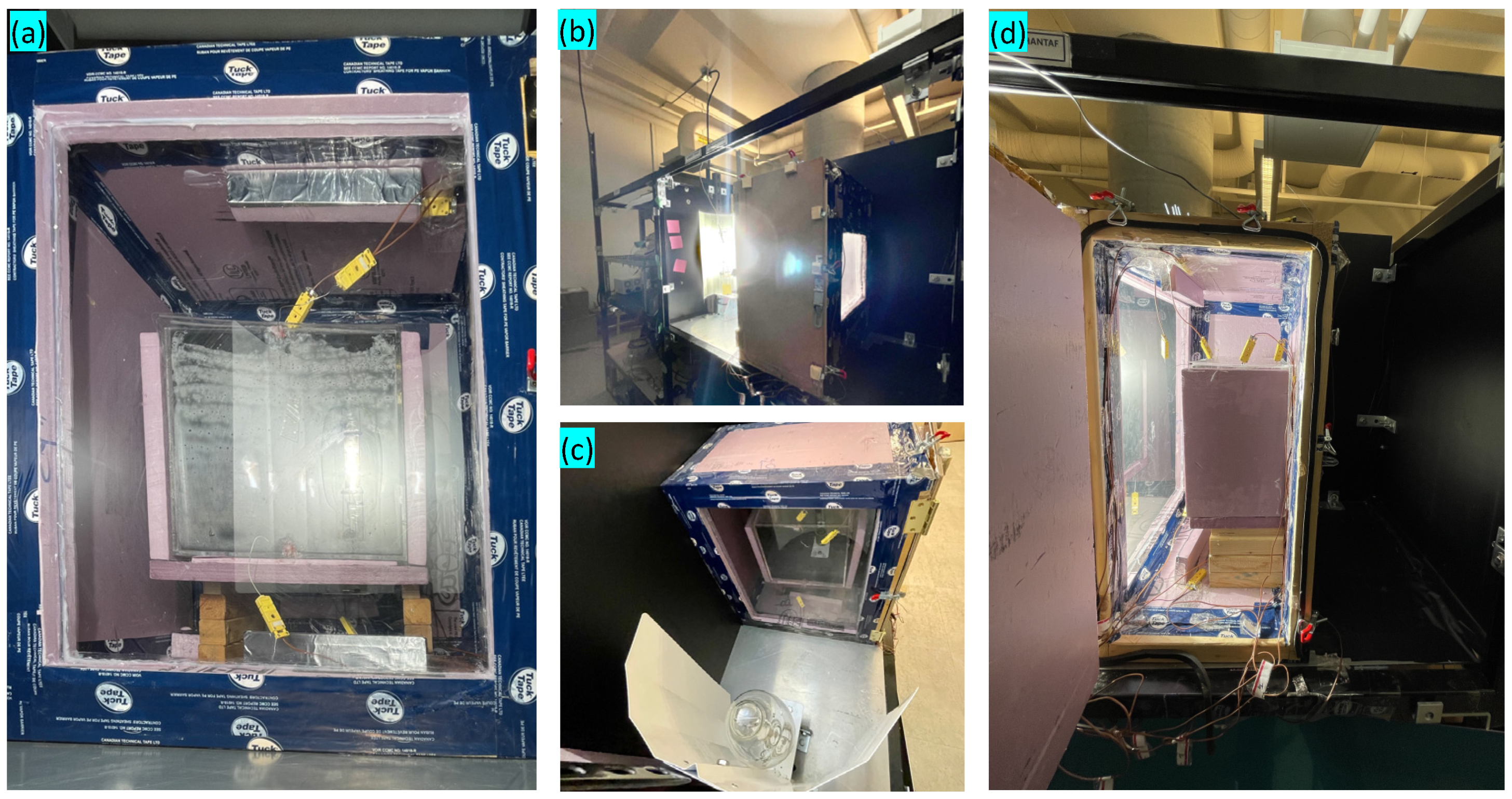
19]. In this work, we have modified this Trombe wall prototype, shown in Figure 1, to experimentally investigate and compare the ability to store solar thermal energy in water storage walls with and without tinted glass. The Trombe wall prototype was built using 3.8 × 3.8 cm wooden frames because of their low thermal conductivity. The overall dimensions of the model frame were 58.4 × 38.1 × 66.0 cm. The frame wa insulated using 1.5-inch thick FOAMULAR extruded polystyrene insulation boards (which have a thermal conductivity of 0.029 W/m·K). Silicon sealant was used to assemble the prototype.
The front surface of the Trombe wall prototype was made from a 3 mm thick clear acrylic sheet that was tightly fitted in the insulation board frame and then sealed using silicon sealant at its edges. These seals were subsequently covered with sheathing tape. The reflectance (R) and transmittance (T) of this clear acrylic sheet was measured over the wavelength range extending from 300 nm to 1400 nm using a UV-VIS spectrophotometer (Shimadzu 2600i). The reflectance and transmittance of the clear acrylic sheet over the wavelength range from 1400 nm to 23 μm was measured using an FTIR spectrometer (VERTEX 70). The absorptance (A) of the clear acrylic sheet was determined using the reflectance and transmittance measurements and the equation A + R + T = 1. A 3 mm thick acrylic plexiglass sheet of dimensions 35 cm × 35 cm was integrated into the back side insulation of the prototype. This allowed light to pass through the Trombe wall prototype, as a desired feature of the water Trombe wall in this work was transparency or semi-transparency. The side of the Trombe wall prototype was designed as an insulated door to allow users to change the TES medium and adjust the position of the thermocouples. A 1000 W Hortilux Blue W Metal Halide bulb mounted vertically with a white reflector behind it was used to simulate solar radiation. This light source was 38 cm away from the front surface of the acrylic sheet. The Trombe wall consisted of a TES medium as water and the water was stored in a clear acrylic plexiglass container. The dimensions of the water container were 30 × 20 × 20 cm. Some experiments were run with a 5 mm thick tinted acrylic sheet (manufactured by Chemcast) integrated into the TES medium at the front of the water container. Similar to the clear acrylic sheet at the front of the Trombe wall prototype, the reflectance, transmittance and absorbance of the tinted acrylic sheet were determined using UV-VIS and FTIR measurements. The plexiglass container, with and without the tinted acrylic sheet, is shown in Figure 2. In addition, experiments were run with either one or two 3 mm thick clear plexiglass sheets at the rear side of the Trombe wall prototype to investigate the effects of having better insulation at the “inside” of the Trombe wall (the air gap between the two clear sheets acted as an insulative layer). These clear plexiglass sheets at the rear side of the Trombe wall prototype were separated by 2.5 cm.
Eight type-K thermocouples were placed in different locations within the water thermal storage medium, as shown in Figure 3. Thermocouples T1 and T7 were installed 2.5 cm away from the front (light-facing) side of the water storage medium at the top-center and bottom-center, respectively. Similarly, thermocouples T2 and T8 were installed close to the back side (2.5 cm away from the rear side at the center) at the top and bottom of the water container, respectively. Thermocouples T3, T4, and T5 were mounted in the horizontal mid-plane of the water container at 2.5 cm, 7.5 cm, and 17.5 cm from the front of the container, respectively, and 15 cm from the top of the water storage medium. Thermocouple T6 was mounted in the mid-plane of the container 2 cm from its right side (the side facing the door of the Trombe wall prototype, as shown in Figure 1d) and 15 cm from the top. A Labjack data acquisition system (T7-Pro) was used to capture the readings from the thermocouples. Experiments were conducted to determine the temperature profiles over time for thermocouples T1 through T8 for four cases of different thermal storage medium configurations, as summarized in Table 1.
Each experiment consisted of a charging period followed by a discharging period. The charging period was initiated by turning on the solar simulator lamp. The charging period lasted for 5 h and was completed by turning the lamp off. The temperature measurements were continued as the discharging phase proceeded with the lamp off. The total duration of each experiment was 24 h. The Trombe wall prototype door and vents were always closed for these experiments, which is the expected operating configuration for summer conditions.
The thermal storage efficiency of the Trombe wall prototype was estimated as the ratio of the thermal energy stored in the water-based storage medium at the end of the charging phase (when the light was switched off at the 5-h mark of the experiment) to the amount of light energy incident onto the plexiglass sheet at the front of the Trombe wall prototype. This thermal storage efficiency was expressed numerically in Equation (1):
η = Q TES Q i ,
where, Q T E S is the thermal energy stored in the water at the end of the charging phase and Q i is the total radiant energy incident onto the window of the Trombe wall prototype during the charging period. Equation (2) was used to estimate Q T E S :
Q T E S = m × c p × Δ T ,
where, m is the mass of the water in the storage medium, c p is the specific heat of water, and Δ T is the different between the average temperature of the water at the end and the beginning of the charging period. For Cases 2 and 4, wherein a tinted acrylic sheet was inserted into the water storage medium at its front face, the difference between the heat capacity of the acrylic in the water was not taken into consideration in the calculations (it was assumed the entire volume within the water container was occupied with water). This assumption was reasonable because the thickness of the tinted acrylic sheet was much less than that of the water storage medium (5 mm as compared to 20 cm). Furthermore, Q T E S was determined by first calculating the amount of thermal energy stored in the top and bottom halves of the water storage medium, and then summing the results together afterwards. The average temperature in top and bottom halves of the water storage medium were determined using Equations (3) and (4), respectively:
T a v g , t o p = T t o p + T m i d d l e 2 ,
T a v g , b o t t o m = T m i d d l e + T b o t t o m 2 ,
where Ttop, Tmiddle, and Tbottom are the average measurements from the thermocouples located at the top, middle and bottom of the water storage medium, respectively.
Equation (5) was used to calculate Q i :
Q i = a v e r a g e   i n c i d e n t   r a d i a n t   e n e r g y   f l u x × t i m e × a r e a ,
To calculate the average incident radiant energy from the solar-simulated light provided by the lamp, the plexiglass at the front of the Trombe wall prototype was considered to be divided into equal areas in a 3 × 3 mesh. The incident light intensity was then measured at the center of each of the nine areas in the mesh using a power meter (THORLABS, PM 100D), and the average of these measurements, which was 44.4 mW/cm2, was taken as the average incident radiation. The time used to calculate Q i was five hours, which was the time during which the lamp was on during the charging phase. The area of the acrylic sheet at the front of the Trombe wall prototype (57.2 cm × 43.2 cm = 2468 cm2) was used as the area in Equation (5).
The power meter was also used to measure the amount of radiant energy that passed through the window at the rear side of the Trombe wall prototype. Furthermore, the error values on the thermal energy stored and the thermal efficiency, reported in Table 2, were determined assuming the error on the thermocouple measurements was ±2.2 °C and the error on the power meter used to measure the light intensity was ±3% (these error values were in accordance with the technical specifications for the measuring devices used). The error on the other values used in the calculations (such as the area of the acrylic sheet, and the time the light was on) were much smaller in comparison and were assumed to be negligible.

3. Results

3.1. Temperature Profiles throughout the Trombe Wall Prototype

The resulting temperature profiles for Case 1, when the TES medium was water and there was a single sheet of plexiglass at the rear side of the Trombe wall prototype, are shown in Figure 4a. The temperature of the thermocouples at the top of the water container (T1 and T2) increased to ~47 °C during the 5-h charging period. After the lamp was turned off, the temperature of T1 and T2 gradually cooled down to ~26 °C by the end of the 19-h discharging period. The temperature of T3, T4, T5, and T6 at the middle of the water container increased to ~35 °C after the light was on for 5 h. The temperature at the end of the discharging period was also ~26 °C for the thermocouples located at the middle of the water container. The temperature of the thermocouples near the bottom of the water container (T7 and T8) increased to ~32 °C during the 5-h charging period. After the lamp was turned off, the temperature dropped down to ~25 °C by the end of the 19-h discharging period.
The temperature profiles for Case 2, wherein water with a tinted acrylic sheet was used as the storage medium and there was a single sheet of plexiglass at the rear side of the Trombe wall, are shown in Figure 4b. The temperature of the thermocouples at the top of the water storage medium, T1 and T2, were elevated to ~56 °C and ~54 °C after the 5-h charging period. After the lamp was turned off, the temperature at the top of the water storage medium had dropped to ~29 °C by the end of the 19-h discharging period. The temperature at the mid-plane of the water storage medium increased to ~39 °C after the light was on for 5 h. When the lamp was turned off, the temperature cooled and reached ~29 °C by the end of the discharging phase. The temperature at the bottom of the water storage medium increased up to ~32 °C during the 5-h charging period and then dropped to ~27 °C by the end of the 19-h discharging period.
The resulting temperature profiles, from the experiment when water was used as a TES medium and two clear plexiglass sheets resided at the rear side of the Trombe wall prototype, are shown in Figure 4c. The temperature at the top of the water container increased to ~52 °C during the 5-h charging period, and then decreased to ~27 °C by the end of the discharging period. The temperature at the middle of the water container increased to ~35 °C after the light was on for 5 h, and then dropped to ~28 °C by the end of the discharging period. The temperature near the bottom of the water container increased to ~34 °C during the 5-h charging period, and after the lamp was turned off the temperature had dropped down to ~27 °C by the end of the 19-h discharging period.
The resulting temperature profiles when water was used as the storage medium with a tinted acrylic sheet and double clear plexiglass sheet integrated at the back side of the Trombe wall are shown in Figure 4d. The temperature at the top of the water storage medium was elevated to ~56 °C and ~54 °C (as measured by T1 and T2, respectively) at the end of the 5-h charging period. After the lamp was turned off, the temperature of T1 and T2 dropped to ~29 °C by the end of the 19-h discharging period. Notably, there was flexibility in how the heated water at the top of the water storage medium could be used. The heated water could be removed from the storage medium as soon as it was no longer being heated (when the light was turned off in this experiment) or it could be stored and used to heat water or air at a later time. For example, for the case shown in Figure 4d the temperature at the top of the water storage medium was still 40 °C four hours after the light had been switched off. In practice, hot water could be used to supply hot air to the building for hours after sunset by opening the Trombe wall vents. Alternatively, pre-heated water might not be needed to satisfy building demands during the hours when sunlight is available, but might be useful hours after the sunset. In this scenario the water-based Trombe wall can act as a storage medium until the hot water is needed a few hours after sunset.
For case 4, as shown in Figure 4d, the temperature of the thermocouples at the mid-plane of the water storage medium (T3, T4, T5, and T6) increased to ~42 °C when the light was on for 5 h. When the lamp was turned off, the temperature at the mid-plane cooled and reached ~29 °C by the end of the discharging phase. The temperature of the thermocouples at the bottom of the water storage medium increased to ~35 °C during the 5-h charging period and then dropped down to ~27 °C by the end of the 19-h discharging period.
The temperature of the surrounding air (measured just behind the Trombe wall prototype) and the air inside the Trombe wall prototype were also measured and are reported in Figure S1 in the Supplementary Materials. The temperature of the surrounding air was elevated by about 4 °C during the five-hour period when the light was on for all four cases. Furthermore, for the four cases, the air at the bottom and top of the Trombe wall prototype reached temperatures in the ranges of 52–54 °C and 71–73 °C, respectively. These values were comparable to those reported in the literature. For example, Hernández-López et al. reported glass and thermal storage medium temperatures of 44.3 °C and 75.5 °C, respectively, for a Trombe wall under a solar irradiance of 500 W/m2 [20]. Notably, the temperature of the air in the channel between the glass and the thermal storage medium depends on the air flow rate. Considering the Trombe wall vents were closed in this work, heated air became trapped at the top of the Trombe wall prototype and temperature became elevated to as much as 71–73 °C. During summer operation, heat from the Trombe wall air channel can be prevented from entering the occupied zone within the building by keeping the vents closed and by using adequate insulation. Furthermore, for the Trombe wall prototype reported in this work, the air at the top of the Trombe wall was heated by the inside wall of the acrylic sheet at the front of the Trombe wall prototype. As described in Section 3.2, the clear acrylic sheet at the front of the Trombe wall prototype absorbed solar-simulated light from the metal halide lamp which generated heat, and this was transferred to the air in the Trombe wall prototype. Separate temperature measurements indicated the inside of the plexiglass sheet reached temperatures above 75 °C at its center when the lamp was on. The heated air inside the Trombe wall helped to elevate the temperature of the water in the storage wall, and the warm environment inside the Trombe wall allowed for higher thermal energy storage efficiencies to be achieved, although the thermal energy stored in the air within the Trombe wall was not included in the thermal storage efficiency calculations as determined using Equation (1). While it is possible to define other types of efficiencies to describe the performance of Trombe walls, in this work we were interested in the amount of energy stored as heated water and, thus, Equation (1) only considered the thermal energy stored in the water.

3.2. Reflectance, Transmittance and Absorptance

The transmittance, reflectance, and absorptance of the tinted acrylic sheet over the visible spectral range are shown, along with the CIE 1978 eye sensitivity function, in Figure 5a. The eye sensitivity function peaked at 555 nm and the transmittance of the acrylic sheet at this wavelength was 13.4%. The absorptance ranged from ~90% to ~70% over the visible wavelength range. The transmittance, reflectance and absorptance of the tinted acrylic sheet from 300 nm to 2800 nm is shown in Figure 5b. The absorptance was greater than 94% for wavelengths less than 380 nm and over the spectral region from 2200 nm to 2800 nm. The absorptance of the tinted glass sheet over the wavelength range from 800 nm to 1600 nm was relatively low (the average absorptance over this range was less than 60%). In practice, it would be desirable for the absorptance over this wavelength range to be higher, because, since light is not visible at these wavelengths it would be better if it were absorbed by the tinted glass to generate more heat that could be stored in the water, rather than for it to enter the interior of the building during hot weather conditions.
The transmittance, reflectance and absorptance of the clear acrylic sheet at the front of the Trombe wall prototype is plotted in Figure 5c. The absorptance values were greater than 90% for wavelengths less than 390 nm. Further, the absorptance of the clear acrylic also exhibited a peak value of 79% at ~1660 nm and had an average value of over 85% from 2100 nm to 2800 nm. With regards to these high absorptance values, it can be noted that the clear acrylic sheet absorbed a fair amount of solar-simulated light from the metal halide lamp, which, in turn, generated heat within the clear acrylic sheet and this could be transferred to the air within the Trombe wall prototype. Notably, the amount of energy absorbed by the tinted acrylic sheet in the water storage medium could be increased if the absorptance of the clear acrylic sheet at the front of the Trombe wall were to be reduced such that more light could be transmitted.

3.3. Thermal Energy Stored and Thermal Energy Storage Efficiency

The thermal energy stored in the thermal storage medium and the thermal storage efficiency of the Trombe wall prototype for Cases 1 through 4 are given in Table 2. The thermal efficiency for case 1 was 57.9%. The metal halide bulb used in the experiments emitted radiation in the infrared spectral region. Light with infrared wavelengths could be absorbed by the water and acrylic container which raised the temperature of the water. When tinted glass was inserted into the thermal storage medium (Case 2) the thermal efficiency of the Trombe wall prototype increased to 78.7%. When a second layer of plexiglass was used to increase the insulation at the rear side of the Trombe wall prototype (Case 3) the thermal efficiency increased from 57.9% to 60.3%. When tinted glass was inserted into the thermal storage medium and a second sheet of plexiglass was used at the rear side of the Trombe wall prototype the thermal efficiency increased from 57.9% to 83.2%.
As shown in Table 2, the thermal energy stored in the Trombe wall prototype could be increased either by inserting tinted glass into the water to absorb more of the incident light or by adding a second plexiglass sheet to increase the insulation at the rear side of the prototype. However, that the addition of the tinted plexiglass sheet increased the amount of thermal energy stored to a much greater extent than what is achieved by adding a second layer of plexiglass. Specifically, the amount of thermal energy stored increased by 4.4% (from 1.14 to 1.19 MJ) when a second plexiglass sheet was used at the rear side of the Trombe wall prototype, whereas the amount of thermal energy stored increased by 36.0% (from 1.14 to 1.55 MJ) when tinted glass was inserted into the water storage medium. The amount of thermal energy stored increased by 43.9% (from 1.14 to 1.64 MJ) when a tinted glass sheet and an additional plexiglass sheet were used in the water storage medium and at the rear side of the Trombe wall, respectively.
The radiant energy from the solar simulator that was transmitted through the Trombe wall prototype is provided in the last column of Table 2. As expected, there was a trade-off between the amount of thermal energy that could be stored in the water wall and the amount of light energy that could be transmitted through the Trombe wall prototype. Indeed, the amount of radiant energy transmitted over the five-hour duration when the lamp was on ranged from 0.01 MJ for Case 4 to 0.28 MJ for Case 1.

4. Discussion

The highest thermal efficiency estimate in this work was 83.2% for Case 4 when the Trombe wall prototype had tinted glass in the thermal storage medium and two plexiglass sheets at its rear side. It was expected that the thermal efficiency of the Trombe wall could be increased by using a tinted acrylic sheet with a higher absorptance. However, increased absorptance would also reduce the amount of light entering the building. The absorptance of the Trombe wall could also be made to be adjustable to adapt to changing weather conditions throughout the year, such as when a higher absorptance is required during summer months to heat water and reduce the amount of sunlight entering and heating the building. This could be accomplished by making the tinted acrylic sheet removable or by using strips of tinted acrylic that could be rotated (similarly to vertical blinds) to control the portion of light entering the building. Alternatively, using electrochromic windows instead of tinted acrylic sheets is another potential method to control the trade-off between the amount of sunlight used for heating water or used for indoor lighting.
It could also be noted that the efficiencies of the Trombe wall for the four cases reported in this work, which ranged from 57.9 to 83.2%, were comparable to efficiencies reported in the literature. For example, Kara et al. reported an efficiency of 20–36% for a thermal storage wall comprised of PCMs [21]. This efficiency was calculated as the ratio of the energy extracted from the PCM wall to the light energy incident onto the wall. Mohamad et al. defined the efficiency of a water-based Trombe wall as the ratio between the sum of the thermal energy absorbed by the water and the energy carried by the air divided by the amount of solar energy received by the system. Using this definition, the total efficiency was calculated to be greater than 80% for some cases [18]. Zhang et al. calculated an efficiency of 73.5% for a Trombe wall with an aluminum plate absorber located within the air channel. This efficiency was defined as the amount of heat transferred to the air divided by the total radiant solar energy received by the Trombe wall [22]. Hu et al. investigated a novel Trombe wall with blinds for shading and a water flowing channel that could be used to pre-heat water for building applications. The monthly average thermal efficiency was between 20% and 60% from April to September, and was 30% to 50% from December to March [23].
The density of the water in the Trombe wall decreases as it is heated by the solar-simulated light, and the hotter water moves to the top of the thermal storage container. As shown in Figure 4, the difference between the temperatures at the top and bottom of the water storage medium could be greater than 20 °C at the end of the charging period (e.g., for Cases 2 and 4). The capability of the water Trombe wall to move stored thermal energy to the top of the wall in the form of heated water allows for increased functionality that cannot be achieved using traditional Trombe wall materials. That is, the heated water at the top of the Trombe wall can be used for applications other than space heating, especially during the summer months. For example, it has been observed that dishwashers operate at temperatures as low as 38 °C, and comfortable temperatures for showering are between 37–40 °C. Furthermore, the recommended temperature in new washing machines for high efficiency is about 49 °C. Moreover, it is preferrable to store building water in hot water heaters at 60 °C or higher to minimize bacteria, although the water temperature at fixture outlets should be a maximum of 49 °C to prevent scalding injuries. Considering the inlet water temperature to building water tanks is typically less than 20 °C in the summer (and the temperature at the top of the Trombe wall prototype reached ~55 °C for the experiments reported in this work) the inlet water could be preheated in a water-based Trombe wall to help reduce water heating costs and energy consumption in buildings.

5. Conclusions

A laboratory-scale Trombe wall prototype, comprising a water storage medium, was built and tested in the laboratory. The experiments were performed so as to evaluate whether the proposed Trombe wall design could provide heated water during hot-weather operating conditions (when the vents at the top and bottom of the Trombe wall are closed). The best results were attained when a tinted acrylic sheet was placed in the water storage medium and when two clear plexiglass sheets were used at the rear side of the protype to increase insulation. Under these conditions, the thermal storage efficiency of the Trombe wall was 83.2% and the water at the top of the storage medium reached a temperature of ~56 °C after being subjected to illumination from solar-simulated light at an intensity of 44.4 mW/cm2 for 5 h. Future work will involve testing a full size Trombe wall under solar illumination to further verify that the water-based Trombe wall design proposed herein can simultaneously provide multiple functions including the following: (1) the provision of a passive source of heating without causing overheating during hot weather conditions (2) functioning as a window or tinted semi-transparent window, and (3) provision of pre-heated water for building applications.

Supplementary Materials

The following supporting information can be downloaded at: https://www.mdpi.com/article/10.3390/buildings12101632/s1, Figure S1: Temperature profile throughout the Trombe wall prototype for (a) Case 1, (b) Case 2, (c) Case 3 and (d) Case 4. This figure is similar to Figure 4 in the manuscript, however, for all cases the temperature of the air surrounding the Trombe wall prototype has been added as the dotted black line. Furthermore, the temperature of the air inside the Trombe wall prototype at its top and bottom are plotted as the green and brown dotted lines, respectively, for all cases.

Author Contributions

Conceptualization, H.S. and P.G.O.; methodology, H.S. and P.G.O.; formal analysis, H.S. and P.G.O.; investigation, H.S. and P.G.O.; writing—original draft preparation, H.S. and P.G.O.; writing—review and editing, H.S. and P.G.O.; supervision, P.G.O.; funding acquisition, P.G.O. All authors have read and agreed to the published version of the manuscript.

Funding

This research was funded by the Natural Sciences and Engineering Research Council of Canada (NSERC, RGPIN-2017-05987).

Data Availability Statement

Not applicable.

Acknowledgments

Assistance provided by Abdallah Alshantaf in fabricating the Trombe wall proto-type experimental setup is greatly appreciated. The authors also thank Atousa Pirvaram for assistance with the optical measurements.

Conflicts of Interest

The authors declare no conflict of interest.

References

  1. International Energy Agency. Energy Technology Perspectives 2020. Available online: https://www.iea.org/reports/energy-technology-perspectives-2020 (accessed on 7 July 2022).
  2. Güneralp, B.; Zhou, Y.; Urge-Vorsatz, D.; Gupta, M.; Sha, Y.; Patel, P.L.; Fragkias, M.; Li, X.; Seto, K.C. Global scenarios of urban density and its impacts on building energy use through 2050. Proc. Natl. Acad. Sci. USA 2017, 114, 8945–8950. [Google Scholar] [CrossRef] [Green Version]
  3. Howard, B.; Parshall, L.; Thompson, J.; Hammer, S.; Dickinson, J.; Modi, V. Spatial distribution of urban energy consumption by end use. Energy Build. 2012, 45, 141–151. [Google Scholar] [CrossRef]
  4. Vaisi, S.; Pilla, F.; McCormac, D.; McCormack, S.J. Towards urban energy density (UED) definition. In Proceedings of the Energy for Sustainability 2015–Sustainable Cities: Designing for People and the Planet, Coimbra, Portugal, 14–15 May 2015. [Google Scholar]
  5. Daigle, Q.; O’Brien, P.G. Heat Generated Using Luminescent Solar Concentrators for Building Energy Applications. Energies 2020, 13, 5574. [Google Scholar] [CrossRef]
  6. Wang, D.; Hu, L.; Du, H.; Liu, Y.; Huang, J.; Xu, Y.; Liu, J. Classification, experimental assessment, modeling methods and evaluation metrics of Trombe walls. Renew. Sustain. Energy Rev. 2020, 124, 109772. [Google Scholar] [CrossRef]
  7. Saadatian, O.; Sopian, K.; Lim, C.H.; Asim, N.; Sulaiman, M.Y. Trombe walls: A review of opportunities and challenges in research and development. Renew. Sustain. Energy Rev. 2012, 16, 6340–6351. [Google Scholar] [CrossRef]
  8. Hu, Z.; He, W.; Ji, J.; Zhang, S. A review on the application of the Trombe wall system in buildings. Renew. Sustain. Energy Rev. 2017, 70, 976–987. [Google Scholar] [CrossRef]
  9. De Gracia, A.; Navarro, L.; Castell, A.; Ruiz-Pardo, A.; Alvarez, S.; Cabeza, L.F. Solar absorption in a ventilated facade with PCM. Experimental results. Energy Procedia 2012, 30, 986–994. [Google Scholar] [CrossRef] [Green Version]
  10. Sun, D.; Wang, L. Research on heat transfer performance of passive solar collector storage wall system with phase change materials. Energy Build. 2016, 119, 183–188. [Google Scholar] [CrossRef]
  11. Li, W.; Chen, W. Numerical analysis on the thermal performance of a novel PCM encapsulated porous heat storage Trombe-wall system. Solar Energy 2019, 188, 706–719. [Google Scholar] [CrossRef]
  12. Pittaluga, M. The electrochromic wall. Energy Build. 2013, 66, 49–56. [Google Scholar] [CrossRef]
  13. Sun-Lite® Thermal Storage Tubes. 2019. Available online: http://www.solar-components.com/TUBES.HTM (accessed on 12 August 2022).
  14. Wang, W.; Tian, Z.; Ding, Y. Investigation on the influencing factors of energy consumption and thermal comfort for a passive solar house with water thermal storage wall. Energy Build. 2013, 64, 218–223. [Google Scholar] [CrossRef]
  15. Nayak, J.K. Thermal performance of a water wall. Build. Environ. 1987, 22, 83–90. [Google Scholar] [CrossRef]
  16. Turner, R.H.; Liu, G.; Cengel, Y.A.; Harris, C.P. Thermal storage in the walls of a solar house. J. Sol. Energy Eng. Trans. ASME 1994, 116, 183–193. [Google Scholar] [CrossRef]
  17. Upadhya, M.; Tiwari, G.N.; Rai, S.N. Optimum distribution of water-wall thickness in a transwall. Energy Build. 1991, 17, 97–102. [Google Scholar] [CrossRef]
  18. Mohamad, A.; Taler, J.; Ocłoń, P. Trombe wall utilization for cold and hot climate conditions. Energies 2019, 12, 285. [Google Scholar] [CrossRef] [Green Version]
  19. Alshantaf, A.; Singh, H.; O’Brien, P.G. Analysis of a Trombe Wall Prototype with Thermal Energy Storage and Air Vent Management. In Proceedings of the 5th International Conference on Energy Harvesting, Storage and Transfer (EHST’21), Niagara Falls, ON, Canada, 21–23 May 2021. [Google Scholar]
  20. Hernández-López, I.; Vázquez-Beltrán, E.; Xamán, J.; Chávez, Y.; Hinojosa, J.F.; Noh-Pat, F. Heating potential prediction of a trombe wall system under temperature under climate conditions of Mexico: Case of Cwa-Cwb Köppen classification. J. Build. Eng. 2021, 44, 103308. [Google Scholar] [CrossRef]
  21. Kara, Y.A.; Kurnuc, A. Performance of coupled novel triple glass and phase change material wall in the heating season: An experimental study. Solar Energy 2012, 86, 2432–2442. [Google Scholar] [CrossRef]
  22. Zhang, L.; Dong, J.; Sun, S.; Chen, Z. Numerical simulation and sensitivity analysis on an improved Trombe wall. Sustain. Energy Technol. Assess. 2021, 43, 100941. [Google Scholar] [CrossRef]
  23. Hu, Z.; Zhang, S.; Hou, J.; He, W.; Liu, X.; Yu, C.; Zhu, J. An experimental and numerical analysis of a novel water blind-Trombe wall system. Energy Convers. Manag. 2020, 205, 112380. [Google Scholar] [CrossRef]
Figure 1. (a) Front view of the Trombe wall prototype when water with acrylic tinted plexiglass was used (b) Rear view of the transparent Trombe wall prototype showing the plexiglass at its rear side (c) Trombe wall prototype with a 1000 W metal halide light functioning as a solar simulator (d) Side view of the Trombe wall prototype with the door open.
Buildings 12 01632 g001
Figure 2. (a) Acrylic plexiglass water container (front view) (b) Acrylic plexiglass water container (view of side and front) (c) Acrylic plexiglass water container with tinted acrylic sheet (front view) (d) Acrylic plexiglass water container with tinted acrylic sheet (view of side and front).
Buildings 12 01632 g002
Figure 3. Schematic of the experimental setup showing the location of the thermocouples inside the water storage medium.
Buildings 12 01632 g003
Figure 4. Temperature profiles throughout the Trombe wall prototype in (a) Case 1, (b) Case 2, (c) Case 3 and (d) Case 4 (The thermal storage medium for the different cases is described in Table 1 and are shown in the insets in this figure).
Buildings 12 01632 g004
Figure 5. (a) The transmittance, reflectance and absorptance of the tinted acrylic sheet shown along with the CIE 1978 Eye Sensitivity Function. The transmittance, reflectance and absorptance of (b) the tinted acrylic sheet and (c) the clear acrylic sheet at the front of the Trombe wall prototype over the wavelength range from 300 nm to 2800 nm.
Buildings 12 01632 g005
Table 1. The thermal storage wall designs experimentally investigated in this work.
CaseDiagramDescription
Case 1Buildings 12 01632 i001
  • The thermal storage wall was made of water in a plexiglass container.
  • The rear side of the Trombe wall had a single plexiglass sheet.
Case 2Buildings 12 01632 i002
  • The thermal storage wall was made of water in a plexiglass container with a tinted plexiglass sheet inserted at the inside of its front face.
  • The rear side of the Trombe wall had a single plexiglass sheet.
Case 3Buildings 12 01632 i003
  • The thermal storage wall was made of water in a plexiglass container.
  • The rear side of the Trombe wall had two plexiglass sheets separated by 2.5 cm.
Case 4Buildings 12 01632 i004
  • The thermal storage wall was made of water in a plexiglass container with a tinted plexiglass sheet inserted at the inside of its front face.
  • The rear side of the Trombe wall had two plexiglass sheets separated by 2.5 cm.
Table 2. Thermal energy stored, thermal storage efficiency, and radiant energy transmitted for the four Trombe-wall prototype cases investigated.
Thermal Energy Stored (MJ)Thermal Storage Efficiency η , (%)Radiant Energy Transmitted through the Trombe Wall Prototype (MJ)
Case 11.14 ± 0.1657.9 ± 10.00.28 ± 0.0084
Case 21.55 ± 0.1678.7 ± 10.70.10 ± 0.003
Case 31.19 ± 0.1660.3 ± 10.10.18 ± 0.0054
Case 41.64 ± 0.1683.2 ± 11.20.01 ± 0.0003
Publisher’s Note: MDPI stays neutral with regard to jurisdictional claims in published maps and institutional affiliations.

