Article

In-Plane Lateral Performance of AAC Block Walls Reinforced with CFPR Sheets

Civil Engineering Department, Australian University-Kuwait, P.O. Box 1411, Safat 13015, Kuwait
*
Author to whom correspondence should be addressed.
Buildings 2022, 12(10), 1680; https://doi.org/10.3390/buildings12101680
Submission received: 31 August 2022 / Revised: 9 October 2022 / Accepted: 11 October 2022 / Published: 13 October 2022
(This article belongs to the Section Building Structures)

Abstract

:
This study evaluates the structural behavior of aerated autoclave concrete (AAC) blocks laterally loaded in the in-plane direction under quasi-static loading. The study started with the evaluation of the basic physical properties of the AAC blocks, including its structural properties (individually and as part of an assembly), followed by large-scale testing of two (half-scaled) walls constructed with commercially available AAC blocks. The first wall was unreinforced, similar to the commonly used construction technique for low-rise houses where AAC blocks are utilized. The second one was internally reinforced with short dowels connecting the foundation to the walls through their lower block rows and externally reinforced with carbon-fiber-reinforced polymer (CFRP) sheets through the entire wall height. The reinforcement scheme was conducted in such a way that does not delay construction time. Reinforcing the wall significantly increased the strength of the wall in the in-plane direction. The reinforced wall exhibited increased initial stiffness, higher ductility, and larger energy dissipation, in addition to a change in the failure mode. The unreinforced wall failure mode was dominated by blocks sliding, while the reinforced wall failure was dominated by compressive shear failure with wall uplifting. The findings of this study can be implemented to increase the lateral strength of unreinforced new houses and can also be extended to strengthen existing houses built with unreinforced AAC blocks.

1. Introduction and Background

Since the mid-1900s, autoclave aerated concrete (AAC) blocks have gained great attention in the construction industry. AAC products are manufactured from a mixture of quartz sand, cement or lime, calcined gypsum, and water, in addition to aluminum powder, which reacts with calcium hydroxide to generate hydrogen gas. This gas then increases the size of the mixture to almost double, with high porosity. The process uses controlled pressures and temperatures of autoclave for the curing process of the blocks to maintain the introduced air voids and achieve high strength [1,2,3].
The main advantages of AAC blocks are: (1) their light weight, which allows the manufacturing and transporting of large block sizes so as to save construction time and transportation efforts, (2) their workability (allowing accurate on-site cutting), (3) their thermal efficiency (especially in hot areas), which results in a great environmental impact on the building life cycle due to the ability to conserve the building operational thermal energy, (4) their relatively high fire resistance, and (5) their great texture that can be exposed for aesthetic purposes, in addition to their great ability to adhere to mortar plasters if finished [1]. On the other hand, AAC blocks have disadvantages, for instance, (1) their relatively lower strength compared to other blocks, (2) their brittle nature, which does not easily allow fixture attachment (e.g., wall-hanging attachments, windows, and doors), and (3) their complicated manufacturing process compared to other types of blocks (e.g., concrete masonry units (CMU), adobe, and compressed earth blocks (CEB)).
Several countries with hot weather (e.g., Gulf Cooperation Council (GCC) countries) specify the use of AAC blocks for exterior walls of various skeleton buildings due to their great thermal insulation abilities (see Figure 1). Recently, houses entirely made of unreinforced AAC walls have been emerging in the construction industry due to their ability to be built faster, with reduced cost and high level of reliability. Figure 2 shows the exterior and interior of one of the houses in the gulf region, which was constructed with unreinforced AAC blocks. In this construction technique, the bottom 500 mm height of all walls is normally constructed using regular CMU blocks, due to their higher strength and moisture resistance, then AAC blocks are used for the remaining parts of the walls.
It should be noted that these houses are unreinforced, which makes them prone to high levels of damage under moderate to high lateral loading. This study suggested the use of carbon-fiber-reinforced polymer (CFRP) sheets as a low-cost technique that can enhance the performance of these walls by increasing their strength and resilience without delaying the construction process.
CFRPs consist of a combination of high stiffness, high strength, lightweight composite materials that have been widely used in different applications during the last few decades. The main advantages of CFRPs are their low cost, low density, high strength-to weight ratio, ability to be applied at any construction stage on structural members (even after the construction is complete for strengthening purposes), and high resistance to corrosion [4,5,6]. Carbon fiber polymers (sheets, strips, cables, and bars) have been used in civil/structural engineering applications (especially for retrofitting and strengthening usages) over the past 30 years for their reliability and durability [4,5,6,7]. Many successful projects have been accomplished with the use of CFRPs on large structures with excellent results (e.g., [7,8,9,10,11,12]).
Lateral behavior of masonry/brick walls had been extensively studied in the in-plane (e.g., [13,14,15,16,17,18]) and the out-of-plane (e.g., [15,19,20,21,22,23,24,25]) orientations. Several studies focused on the use of externally bonded carbon fiber polymers, during the construction phase or for rehabilitation purposes (e.g., [13,14,24,25,26,27]). CFRP lamination to structural members has proven to enhance wall lateral performance, in terms of strength, with reasonable added cost, minimal added self-weight, and with no significant construction time delays. The enhancement of the structural performance is not only limited to static load applications, but also to the dynamic load application. Much research has evaluated the performance of structural members with different CFRP strengthening techniques against dynamic load applications (e.g., seismic, impact, and blast loads). Seismic retrofitting of buildings and bridge columns/piers with various CFRP configurations have been heavily studied both experimentally and analytically (e.g., studies by [28,29,30,31]). The effect of CFRP strengthening on structural members against impact and blast loadings has also been assessed (e.g., studies by [32,33,34,35]) and was proven to increase the energy absorption and decrease the transmitted strains to the structural members with an overall enhanced performance of the members. The use of CFRPs on AAC block walls was also studied by [36,37,38,39] and was found to improve the structural performance of AAC block walls.

2. Research Methodology

The proposed methodology in this study utilizes CFRP laminates (sheets) to increase the in-plane strength of walls made with AAC blocks. At the beginning, the study evaluated the structural performance of AAC blocks and the used grout (i.e., mortar) to build the walls. This is an essential step to investigate and ensure the quality of the used AAC blocks and grout in this study. The structural performance of AAC blocks included compressive and shear bond strength tests for AAC blocks and compressive and tensile bond strength tests for the grout.
Afterwards, the study evaluated the structural performance of two half-scaled walls that were built with AAC blocks. One of the two walls was reinforced with CFRP sheets and the other one remained unreinforced. The walls were tested in their in-plane direction using quasistatic loading. The following sections explain the details and results of individual performance tests conducted for the AAC blocks and the two half-scaled walls.

3. Performance of the AAC Blocks

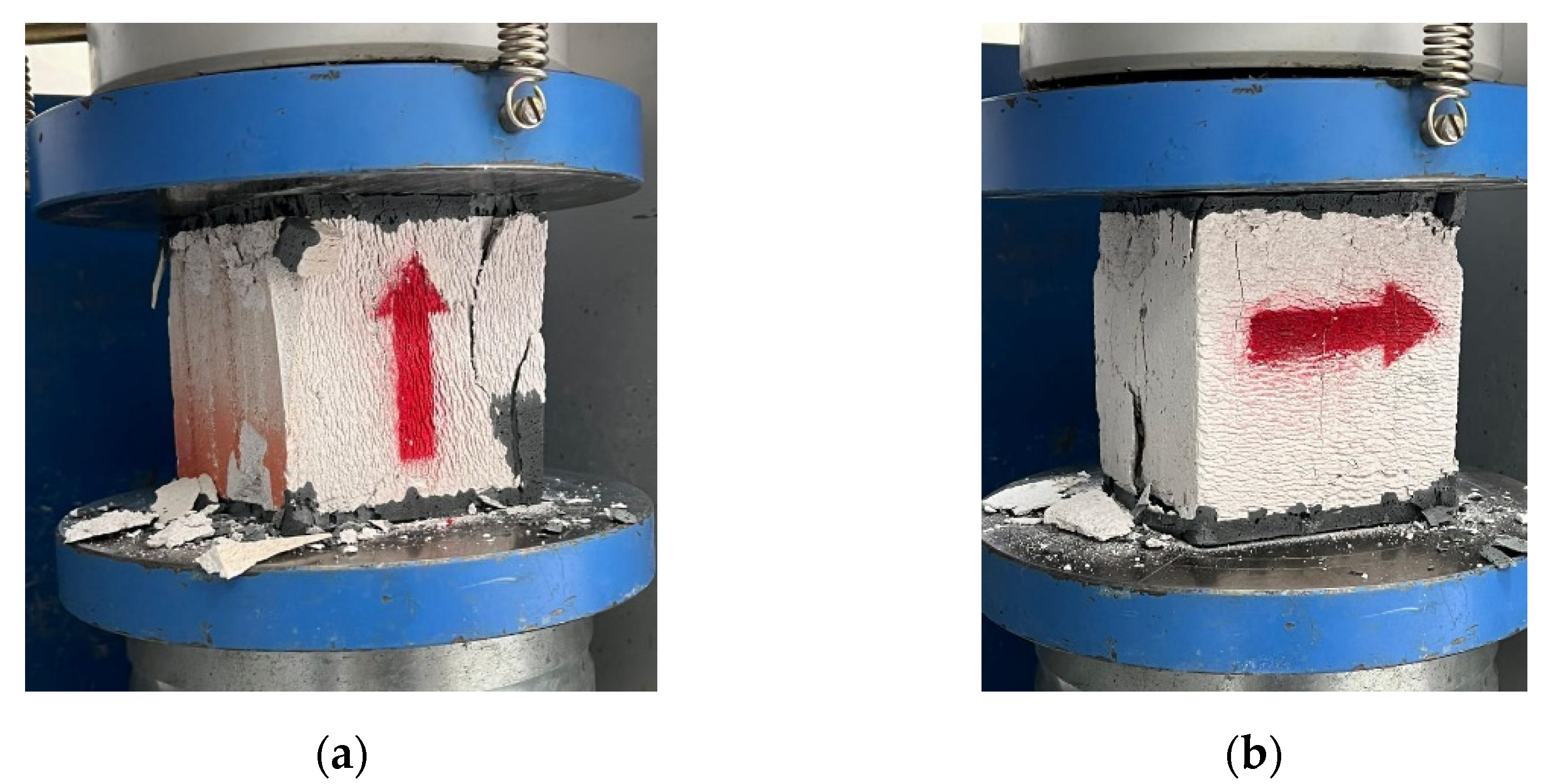
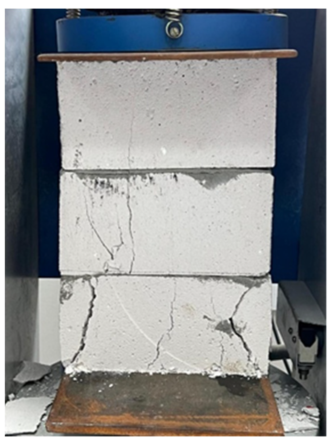
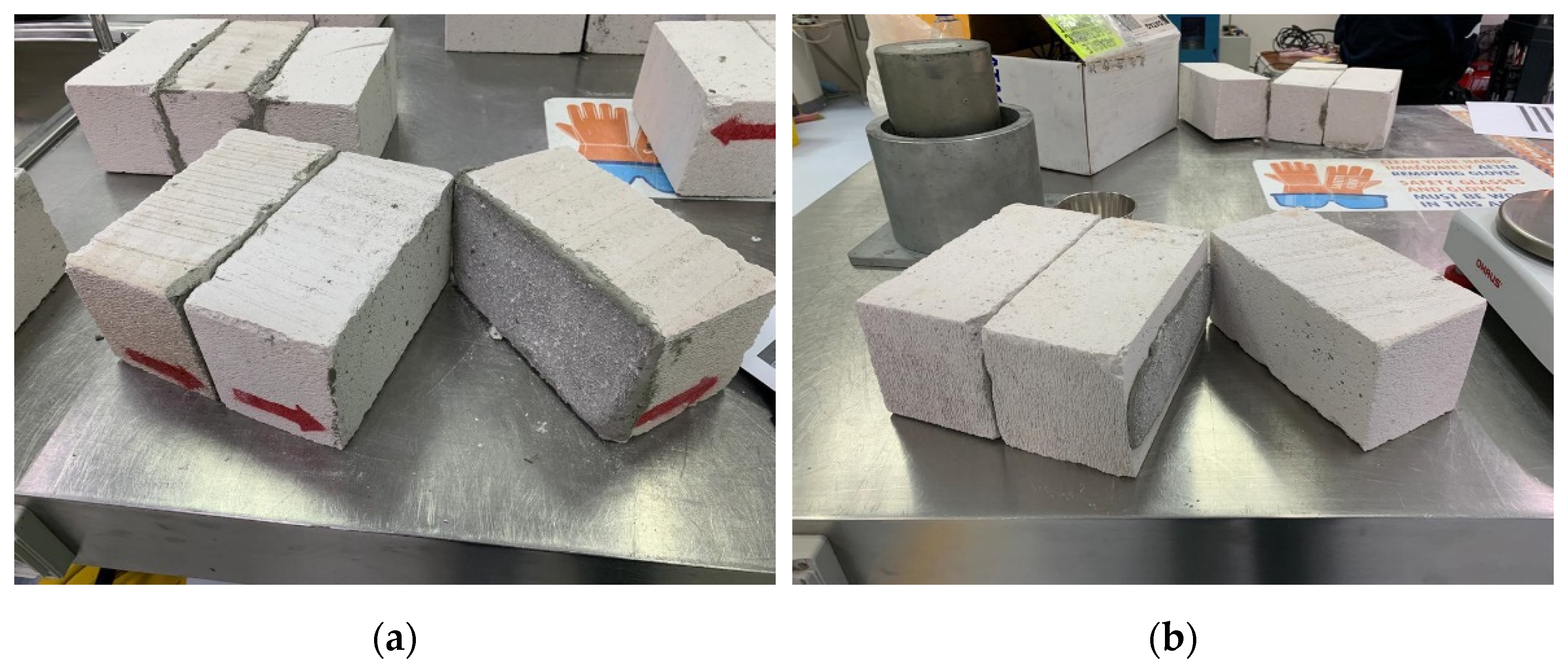
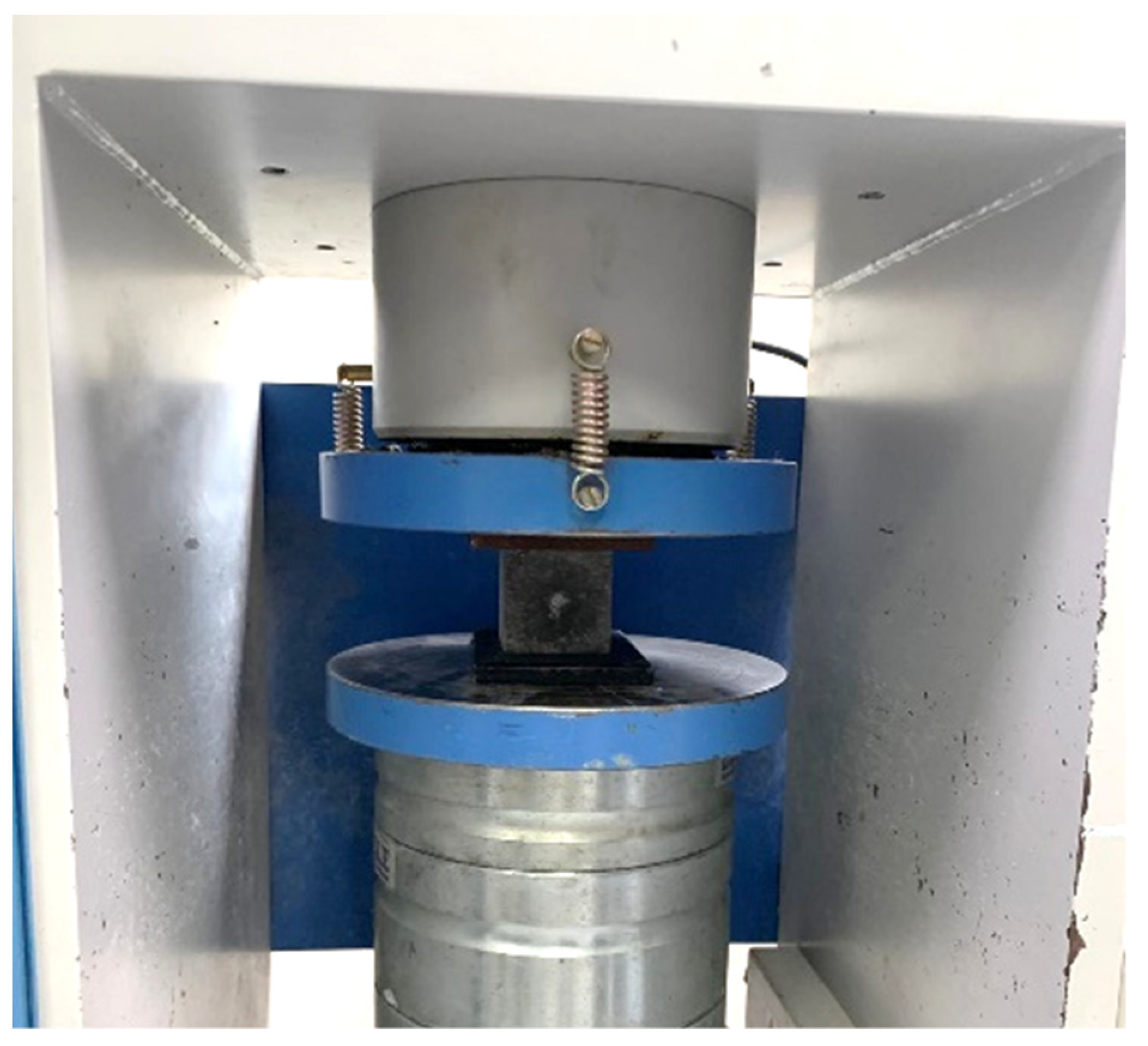
3.1. Compressive Strength

The first step in the evaluation of the AAC blocks was to assess their strength. Compressive strength tests were performed on the blocks in accordance with ASTM C1693 standard [40] under both dry and wet conditions. A total of twelve 100 mm cubes were cut from the AAC blocks and tested in compression (see Figure 3), and the blocks were capped with sulfur caps to ensure uniform distribution of the applied compressive stress during testing. Six of these blocks were tested in compression in the direction parallel to the direction of the wall loading, while the other six were tested in the direction perpendicular to the direction of the wall loading. The reason why the two directions were tested was because the manufacturing process of these blocks normally results in anisotropic behaviors. For each of the six cubes, three blocks were tested under wet condition by being immersed in water at room temperature for 24 h prior to testing. It shall be noted that the vertical direction of the wall loading is perpendicular to the direction of the wall rise, as explained in [41].
In addition, a triplet wall setup was assembled (see Figure 4) with the specified grout and tested for their compressive strength. For the triplet wall, three samples were tested under dry condition only. The compressive strength results of the triplet walls and the cubes are presented in Table 1.
It can be observed that the average compressive strength of the blocks in the parallel direction to the wall loading is about 70% higher than the average compressive strength for the perpendicular direction of the wall loading. This is typical for AAC blocks due to the effect of pore formation during the manufacturing process, which resulted in the anisotropic behaviors. Furthermore, the strength of the AAC blocks was reduced by 15–20%, after being moisture conditioned for 24 h. This indicates that the water has an adverse effect on the performance of AAC blocks since they contain air voids, which allows for capillary action to absorb water when wetted. When comparing the performance of the triplet block assembly to the individual cubes, the triplets exhibited lower compressive strength with higher coefficient of variation. This can be attributed to the fact that the assemblage is composed of grouted blocks, which facilitates the propagation of internal cracks during testing. The outcome of the compressive strength testing matches the results presented in [41].

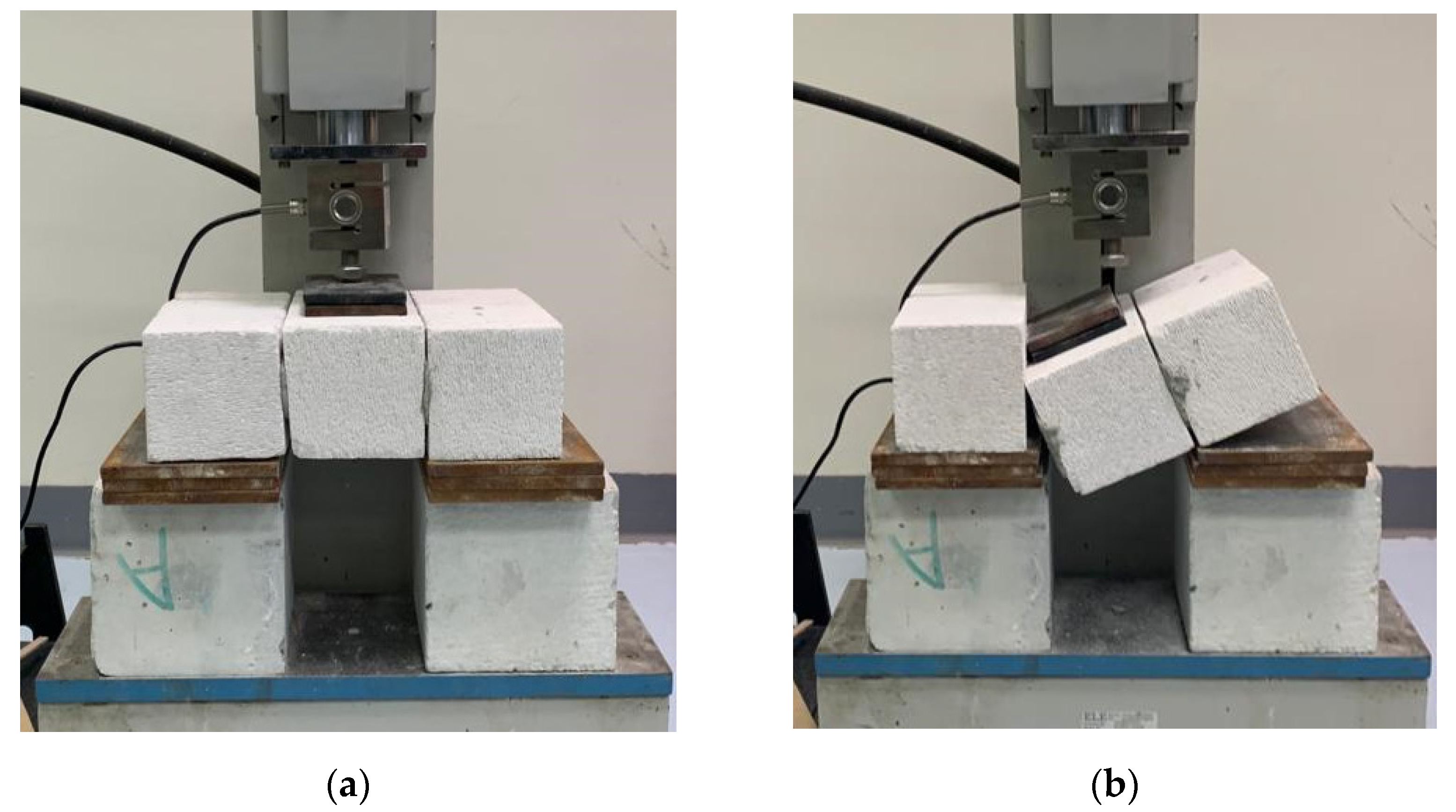
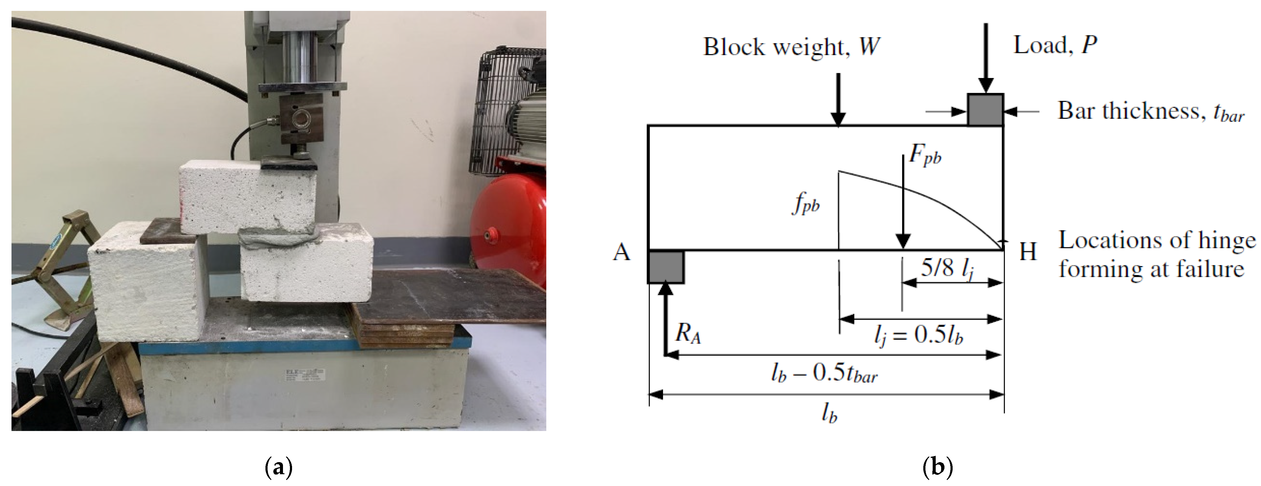
3.2. Shear Bond Strength

Shear bond strength of the block/mortar was evaluated through shear testing in accordance with the procedures outlined in [41]. Six different specimens were tested, and each specimen consisted of an assembly of three blocks that were grouted, as shown in Figure 5. The test was conducted on two different configurations: half-grouted specimens (total of three) and fully grouted specimens (total of three). This way, the two different practices were evaluated in terms of block/mortar bond under shear forces. The shear bond strength results of the tested specimens are presented in Table 2.
The test results showed that the fully grouted specimens exerted about 85% higher shear bond strength than the half-grouted specimens, with a smaller coefficient of variation. It is a practice to use the half-grouted configuration with nonbearing walls (infill walls), whereas, for bearing walls, the practice is to fully grout the blocks to ensure full continuation of the load between the blocks. Figure 6 shows the shear bond failure of the fully grouted and half-grouted tested block assemblies.

3.3. Mortar Testing

The used grout (mortar) was evaluated in both compressive strength and tensile bond strength with the blocks. The compressive strength test was performed in accordance with ASTM C109M [42]. Three 50 mm cubes were tested under compression at 7 days and another three at 28 days (see Figure 7), and the results are shown in Table 3. It was important to make sure that the used grout was not significantly stronger than the used AAC blocks. Therefore, the chosen grout in this study was only 5 to 10% stronger than the AAC blocks, as intended. Mortar tensile bond strength test was performed in accordance with the methodology proposed by [43], which was verified against the British Standards BS 5628 [44], where z-shaped specimens were prepared and tested as illustrated in Figure 8a. The bond strength test results are shown in Table 4. The parabolic stress distribution assumption of the reference was applied in the calculations of the tensile bond strength according to Equation (1) for the joint strength (fpb) and Equation (2) for the total joint force (Fpb) (see Table 4), with the parameters defined in Figure 8b. Two specimens failed through mortar separation, while one failed through AAC block split, which justifies the high value of the coefficient of variation within the test results. The results also showed that the used mortar (grout) is appropriate in building the walls for the large-scale testing of this study, since the attained bond strength (0.32 MPa) for the purpose of this study fell within the minimum required bond strength in various specifications (ranging between 0.2 and 0.8 MPa for different types of mortars) [45,46,47].

4. In-Plane Wall Performance
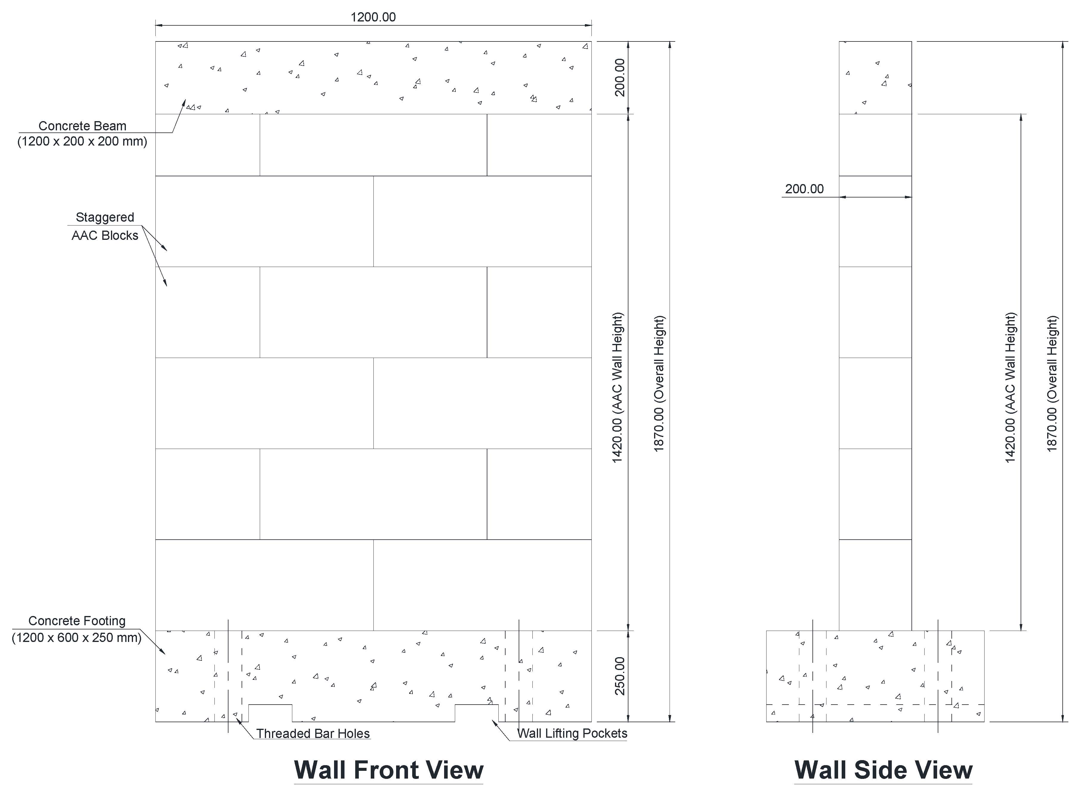
4.1. Wall Specimens

In this study, two half-scaled walls were tested along their in-plane directions using quasistatic loadings. The details of the walls and their construction methodology are explained below.

4.1.1. Unreinforced Wall

The unreinforced wall (shown in Figure 9) was constructed using AAC blocks in a staggered manner with a total height of 1420.00 mm.
The AAC block layers were grouted using a cement-based mortar that is commercially used in the AAC block construction. A reinforced concrete cap was then cast above the wall, and this cap was designed to allow for the distribution of the vertical load (preloading condition) and was also used for the application of the lateral load during testing.

4.1.2. Reinforced Wall

The reinforced wall was constructed using the same blocks (used in the unreinforced walls) connected to the footing using dowel bars that extended to two block layers (500 mm above the footing top level) (see Figure 10). The dowel bars ran through the block layers using predrilled holes with a diameter of 30 mm, which were filled with cementitious grout before the placement of the third block layer (see Figure 11). The dowel bars were eight No. 10 bars spaced equally through the wall width, resulting in a reinforcement ratio of 0.24%. A reinforced concrete cap was also cast above the wall for the same reasons as explained in the unreinforced wall section. Upon completion of the wall construction, vertical and horizontal sheets of CFRPs were laminated on the wall. The CFRPs were made with carbon fiber (CF) sheets that had a thickness of 0.42 mm and a width of 100 mm. The CF was made with 100% carbon fibers that are woven unidirectionally with an average ultimate strength of 400 MPa and an average elasticity modulus of 40 GPa in tension. It was laminated using epoxy-based resin, and then covered with another epoxy layer for protection and to represent the real-life application of CFRP sheets. Four 100 mm wide layers were applied vertically on each wall side, resulting in a vertical reinforcement ratio of 0.14%, and five sheets were applied horizontally on each wall side, resulting in a horizontal reinforcement ratio of 0.15%. The horizontal sheets were wrapped around the two edges of the wall, while the vertical sheets started at the footing top and were wrapped atop the cap beam to avoid slippage during testing (see Figure 10, Figure 11 and Figure 12).
The wall reinforcement methodology provided a more practical approach than placing full vertical reinforcing bars in the wall. Vertical wall reinforcement had always been challenging as it requires the bar placement with its full length, and then the placement of the hollowed blocks through these bars, which causes delays to the construction process. In the proposed methodology, hollowed blocks are only placed at the first two layers. Afterwards, the CFRP reinforcement is externally applied after the completion of the wall construction. Figure 12 shows the installation of the CFRP sheets to the wall after the construction was completed. The vertical sheets were laminated first and then the horizontal sheets.

4.2. Large-Scale Test Setup

The two walls were tested using a hand-operated hydraulic jack that applied the load on the top cap beam (see Figure 13). The walls were vertically preloaded with a compressive load of 48 kN through pre-tensioning the shown vertical threaded bars simultaneously before testing. This load was applied using two strong steel beams placed at one- and two-third locations above the concrete cap beam. Four steel trusses were placed on the sides of the cap beam to ensure that the load is unidirectional and to prevent out-of-plane wall movement.
The applied forces were recorded using a load cell placed at the location of the hydraulic jack. Horizontal displacements were recorded using unidirectional string pots placed at the hydraulic jack and at three other locations along different heights of the wall (lower, middle, and high). The lateral load application was performed very slowly (quasistatic loading) using a hand-operated jack until failure. Failure here was defined as the observation of a large drop in the wall strength with failure signs on the specimens.

4.3. In-Plane Lateral Performance of the Walls

The unreinforced wall experienced block sliding of the second row of blocks against the first row, followed by uplifting of the wall (at the tension side) above the first row and then compressive shear failure of the wall on the compression side. The compressive shear failure developed a vertical shear crack through the whole wall (see Figure 14). The high compressive force resulted in shearing the last block of the first row, along with spalling the concrete cover of the footing at the compression side of the wall (see Figure 15). The final residual displacement at the loading point of the wall was 30 mm.
On the other hand, the reinforced wall experienced high compressive forces on the compression side, resulting in localized failure of the blocks at the first and second rows, with local buckling of the vertical CFRP sheets on both sides of the wall (see Figure 16 and Figure 17). This behavior was followed by uplifting of the wall under the first row (at the intersection with the footing), which indicated the slippage of the dowel bars, with no signs of failure in the remaining parts of the wall or the CFRP sheets. No damage in the concrete footing or the dowel bars was observed. Upon the release of the jack force, the gap caused by the wall uplifting was closed, with smaller residual displacement compared to the unreinforced wall (24 mm at the loading point of the wall).
The force–displacement relationships for the tested walls are shown in Figure 18. It can be observed that reinforcing the AAC wall with the proposed methodology significantly enhanced the lateral performance of the wall in the in-plane direction. As illustrated in Table 5, the recorded initial stiffness of the reinforced wall was more than twice the recorded initial stiffness of the unreinforced wall. This observation is very promising in preventing damage under low to moderate levels of earthquake, especially given that the observed failure mode of the unreinforced walls was sliding of the blocks, which is costly and challenging in its repair. Moreover, the dissipated energy (the area under the force–displacement curve) of the reinforced wall was about four times the dissipated energy in the unreinforced wall, which indicates very good ability of this wall to prevent/reduce damage in other members in the building during an event of high levels of earthquakes. It was also observed that the ultimate force (@ failure force) was increased from 25.7 kN for the unreinforced wall to 62.2 kN for the reinforced wall. This significant increase is a great outcome of this study, as it shows that the CFRP reinforcement substantially enhanced the lateral performance of the unreinforced buildings with a methodology that is not costly and does not delay the construction process.
Furthermore, the observed damage, together with the residual displacement in the reinforced wall, was much less than the damage that occurred in the unreinforced wall. The unreinforced wall damage was spread over the whole wall (shear cracking and sliding), which implies costly repairs in post-earthquake events. In contrast, the damage in the reinforced wall was very minimal and localized, and this can be easily repaired at low cost compared to the unreinforced wall.

5. Cost Analysis of the Used Method

To assess the added cost of the used method, a simple scenario of a residential building is introduced in this section with real-life prices in the GCC region. The scenario is for a two-story residential house with a footprint of 300.0 m2, and the following assumptions were used based on the collected data from contractors in the region (Table 6 summarizes the total cost for reinforcing this residential house):
-
Building floor heights are of 4.0 m in addition to 1.0 m height between the footings and the ground floor, and the total height of the loading bearing walls is 9.0 m.
-
The average cost of construction is USD 500 per square meter for medium finishing criteria, resulting in a total price of construction equal to USD 300,000 for this building. This value includes the structural, civil, and architectural work, and excludes the land and furniture cost.
-
In this scenario, four (two-meter wide) walls are reinforced with CFRPs (to the full height) to increase the lateral resistance by following the proposed methodology of this study (two walls in each direction for symmetry).
-
The price of each 100 m roll of the CFRPs was USD 200, including shipping, which results in a price of USD 2.0 per meter of the CFRPs (100-mm-wide sheets).
-
The external walls are assumed to have a thickness of 200.0 mm and, hence, a reinforcement ratio of 0.15% (similar to the study walls) requires 7 × 100-mm-wide sheets on each side vertically (total of 14 sheets per wall).
-
Similarly, to reach the same ratio in the horizontal direction, a total of ten 100-mm-wide sheets are required on each side (total of 20 sheets per wall).
-
By multiplying the lengths and the number of sheets, the total length of the required CFRP sheets per wall is 126.0 m.
-
The cost of the used epoxy resin bucket in this study was USD 40 and was sufficient to laminate 10.0 m length of the 100 mm wide sheets, which results in a price of USD 4.0/m.
-
Assuming the use of 11 No. 16 mm bars as dowels, with a length of 1.5 m per dowel, results in 106 kg of reinforcing bars for all four walls.
The total added cost for reinforcing four walls in a small residential house was less than 1.5% of the total construction cost of the building, which is a negligible added cost for the added benefit to the lateral performance of the building. It shall be noted that these prices were obtained from the actual purchased items in the research project and by contacting several contractors in the GCC countries and may be different in different regions.

6. Conclusions

This study evaluated the structural performance of aerated autoclave concrete (AAC) blocks through large-scale testing. It started with assessing the structural performance of the induvial AAC blocks, and then tested the in-plane lateral performance of half-scaled walls subject to quasistatic loading. Two identical walls were built using AAC blocks: one was unreinforced, the other one was externally reinforced using carbon-fiber-reinforced polymer (CFRP) that was laminated on both sides of the wall vertically and horizontally. The reinforced wall was connected to the footing by dowel bars that were internally extended for 500 mm inside the wall, and the following conclusions were drawn:
  • Several performance tests were conducted on the used AAC blocks and grout in this research study. The tested AAC blocks, and the grout showed good structural performance, which confirmed the quality of the used materials before building the large-scale walls.
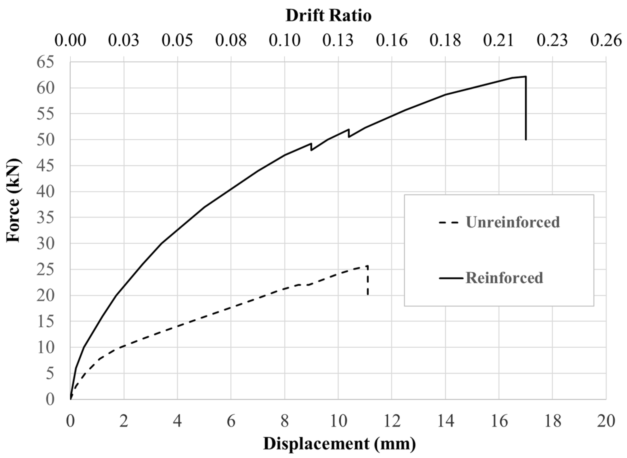
  • Reinforcing the AAC wall with CFRPs significantly enhanced their in-plane lateral performance. The initial stiffness of the tested wall was increased from 12.5 kN/mm to 30.0 kN/mm with a 140% increase, the dissipated energy was increased from 181.09 kN.mm to 741.54 kN.mm with a 300% increase, and the ultimate lateral force increased from 25.7 kN to 62.2 kN with a 142% increase.
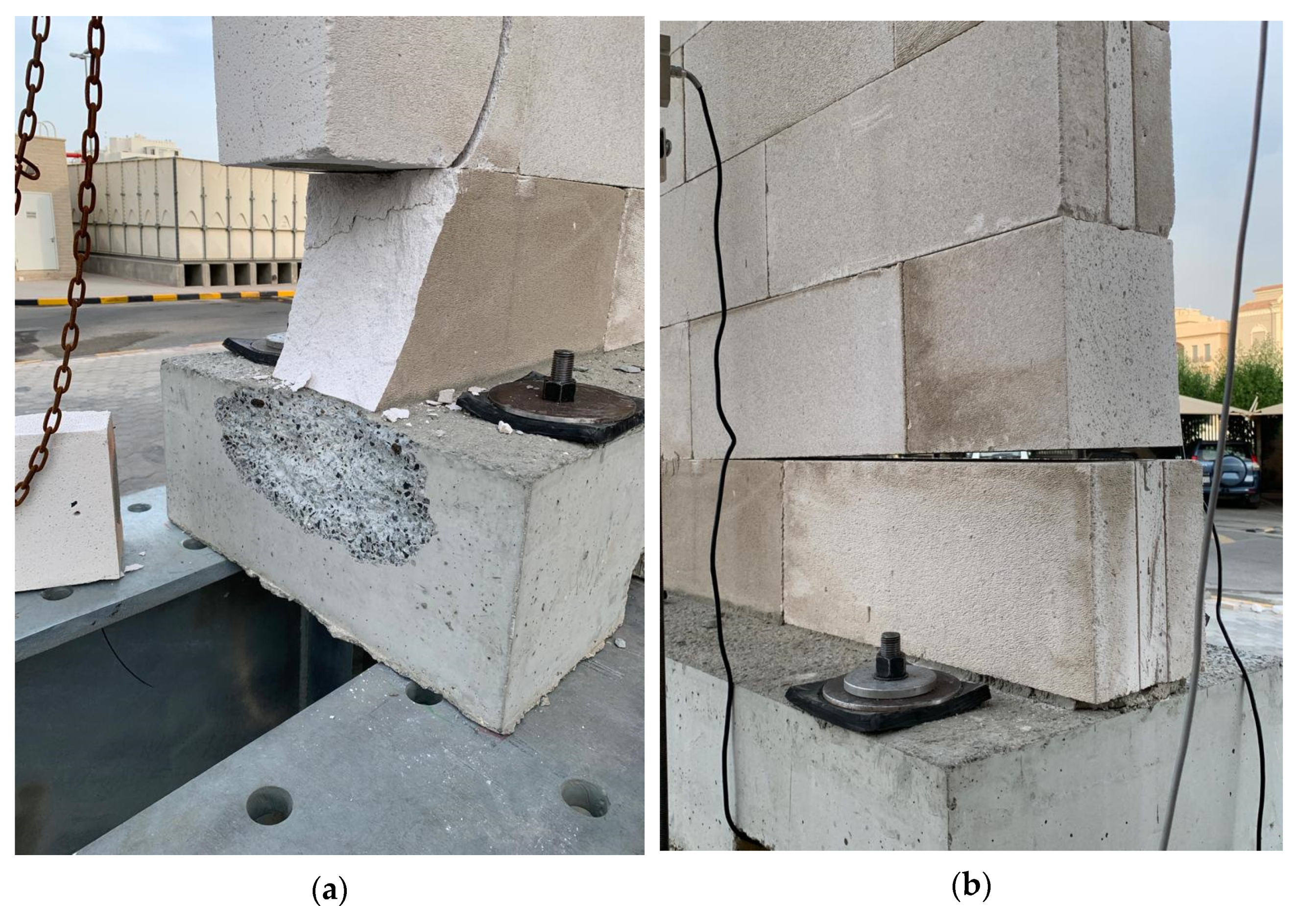
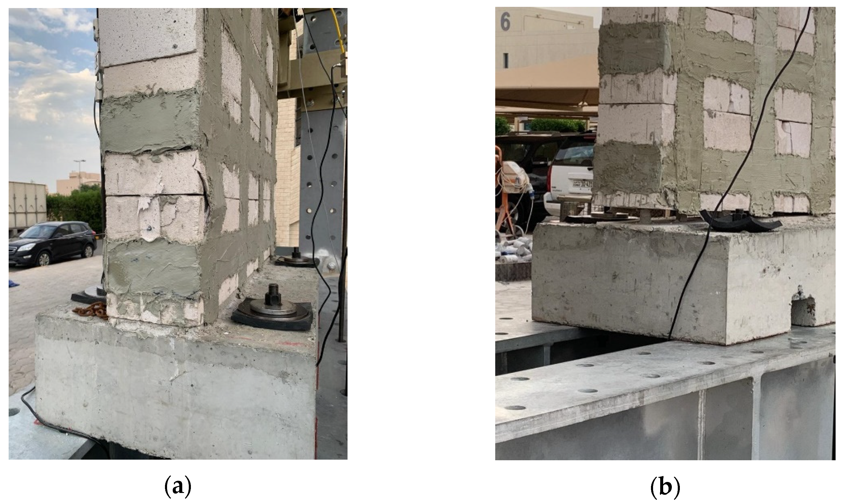
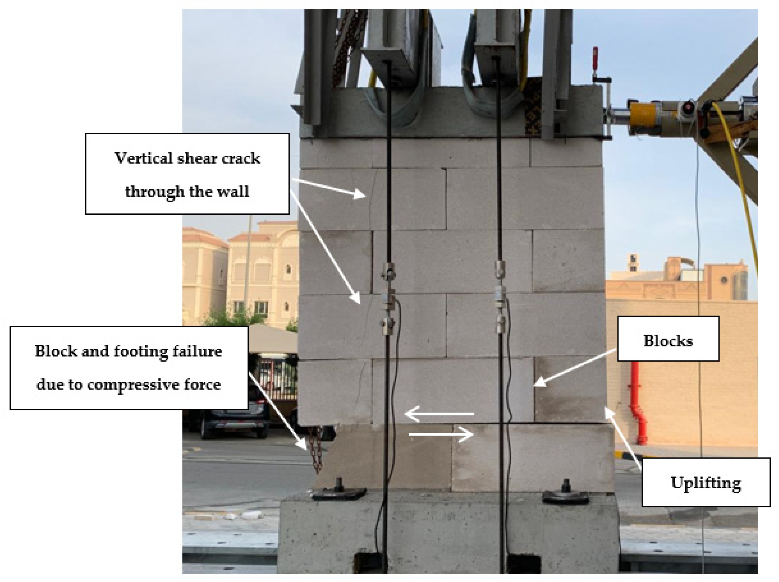
  • The failure mode of the unreinforced AAC wall was dominated by sliding of the block rows, followed by uplifting and compressive shear failure at the compression side, resulting in a shear crack that extended through the whole wall. Alternatively, the reinforced wall experienced much less damage and its failure was dominated by slippage of the dowel bars, causing wall uplifting at the tension side, followed by localized compressive shear failure and buckling of the CFRP sheets on the compression side of the wall. No signs of global damage to the reinforced wall were observed.
  • CFRP sheets also reduced the recorded residual displacements of the wall, which indicated reduced damage in post-lateral load application events.
  • Cost analysis showed that the total added cost for reinforcing the AAC walls with CFRPs was less than 1.5% of the total construction cost of the building, which was insignificant compared to the added value to the lateral performance of the building.
The proposed methodology in this study can be easily used for construction of new low-rise buildings, causing no delay in construction time, and can also be used in strengthening of existing unreinforced structures made with AAC blocks.

7. Recommendations for Future Work

Since the reinforced wall failure mode was dominated by its uplifting on the tension side, with slippage occurring at the dowels’ connections with the blocks, it is recommended to study the dowel length and their configurations at the wall connection. The authors recommend assessing different bar sizes and embedment lengths, in addition to grout (mortar) mix designs to determine the best possible configuration to embed dowels in AAC blocks. The orientation and reinforcement ratio of CFRPs shall also be assessed to optimize the performance of the reinforced wall against lateral loads. It is also recommended to test the proposed methodology under cyclic loading to assess its ability to withstand multiple cycles of lateral loading rather than a unidirectional loading. Furthermore, lateral building analyses can evaluate the added strength of this new methodology on a system level, rather than an individual wall level.

Author Contributions

Conceptualization, A.S.S. and T.A.A.; Data curation, A.I.R.; Formal analysis, A.S.S. and A.I.R.; Investigation, A.I.R.; Methodology, A.S.S. and T.A.A.; Writing—original draft, A.S.S.; Writing—review and editing, T.A.A. All authors have read and agreed to the published version of the manuscript.

Funding

This research received no external funding.

Data Availability Statement

The datasets generated during and/or analyzed during the current study are available from the corresponding author on reasonable request.

Conflicts of Interest

The authors declare no conflict of interest.

References

  1. Snow, C.A. A comprehensive Study of the Material Properties and Structural Behavior of AAC Products. Ph.D. Dissertation, University of Alabama at Birmingham, Birmingham, UK, 1999. [Google Scholar]
  2. Chen, Y.; Peng, M.; Zhang, Y.; Liu, Y. Mechanical properties of autoclaved aerated concrete with different densities. Adv. Civ. Eng. Mater. 2013, 2, 441–456. [Google Scholar] [CrossRef]
  3. The History of AAC. Available online: https://web.archive.org/web/20101204154720/http://www.hebel.co.nz:80/about/hebel%20history.php (accessed on 9 August 2019).
  4. Priestley, M.J.N.; Seible, F. Design of seismic retrofit measures for concrete and masonry structures. Constr. Build. Mater. 1995, 9, 365–377. [Google Scholar] [CrossRef]
  5. Bakis, C.E.; Bank, L.C.; Brown, V.; Cosenza, E.; Davalos, J.F.; Lesko, J.J.; Machida, A.; Rizkalla, S.H.; Triantafillou, T.C. Fiber-reinforced polymer composites for construction—State-of-the-art review. J. Compos. Constr. 2002, 6, 73–87. [Google Scholar] [CrossRef] [Green Version]
  6. Hollaway, L.C. A review of the present and future utilisation of FRP composites in the civil infrastructure with reference to their important in-service properties. Constr. Build. Mater. 2010, 24, 2419–2445. [Google Scholar] [CrossRef]
  7. Siddika, A.; Al Mamun, M.A.; Alyousef, R.; Amran, Y.M. Strengthening of reinforced concrete beams by using fiber-reinforced polymer composites: A review. J. Build. Eng. 2019, 25, 100798. [Google Scholar] [CrossRef]
  8. Phares, B.M.; Wipf, T.J.; Klaiber, F.W.; Abu-Hawash, A.; Lee, Y.S. Strengthening of steel girder bridges using FRP. In Proceedings of the 2003 Mid-Continent Transportation Research Symposium, Ames, IA, USA, 21–22 August 2003. [Google Scholar]
  9. Hutchinson, R.; Tadros, G.; Kroman, J.; Rizkalla, S. Use of externally bonded FRP systems for rehabilitation of bridges in Western Canada. ACI Spec. Publ. 2003, 215, 239–248. [Google Scholar]
  10. Klaiber, F.W.; Wipf, T.J.; Kempers, B.J. Repair of damaged prestressed concrete bridges using CFRP. In Proceedings of the 2003 Mid-Continent Transportation Research Symposium, Ames, IA, USA, 21–22 August 2003. [Google Scholar]
  11. Olofin, I.; Liu, R. The application of carbon fibre reinforced polymer (CFRP) cables in civil engineering structures. Int. J. Civ. Eng. 2015, 2, 1–5. [Google Scholar] [CrossRef]
  12. Zhai, K.; Fang, H.; Guo, C.; Ni, P.; Fu, B.; Wang, F.; Zhang, C. Strengthening of PCCP with broken wires using prestressed CFRP. Constr. Build. Mater. 2021, 267, 120903. [Google Scholar] [CrossRef]
  13. Valluzzi, M.R.; Tinazzi, D.; Modena, C. Shear behavior of masonry panels strengthened by FRP laminates. Constr. Build. Mater. 2002, 16, 409–416. [Google Scholar] [CrossRef]
  14. ElGawady, M.A.; Lestuzzi, P.; Badoux, M. Aseismic retrofitting of unreinforced masonry walls using FRP. Compos. Part B Eng. 2005, 37, 148–162. [Google Scholar] [CrossRef]
  15. Memari, A.M.; Grossenbacher, S.V.; Iulo, L.D. In-plane and out-of-plane load testing and evaluation of sustainable masonry walls. In Proceedings of the Architectural Engineering National Conference, Denver, CO, USA, 24–27 September 2008. [Google Scholar]
  16. Bland, D.W. In-Plane Cyclic Shear Performance of Interlocking Compressed Earth Block Walls. Master’s. Thesis, Faculty of California Polytechnic State University, San Luis Obispo, CA, USA, 2011. [Google Scholar]
  17. Qu, B.; Stirling, B.J.; Laursen, P.T.; Jansen, D.C.; Bland, D.W. Interlocking compressed earth block walls: In-plane structural response of flexure-dominated walls. In Proceedings of the 15th World Conference on Earthquake Engineering, IIAE, Lisbon, Portugal, 28 September 2012. [Google Scholar]
  18. Celano, T.; Argiento, L.U.; Ceroni, F.; Casapulla, C. Literature review of the in-plane behavior of masonry walls: Theoretical vs. experimental results. Materials 2021, 14, 3063. [Google Scholar] [CrossRef] [PubMed]
  19. Drysdale, R.G.; Essawy, A.S. Out-of-plane bending of concrete block wall. J. Struct. Eng. 1988, 114, 121–133. [Google Scholar] [CrossRef]
  20. Rodriguez, R.; Hamid, A.A.; Larralde, J. Flexural behavior of post-tensioned concrete masonry walls subjected to out-of-plane loads. Struct. J. 1998, 95, 61–70. [Google Scholar]
  21. Vaculik, J.; Griffith, M.C.; Hogarth, B.; Todd, J. Out-of-plane flexural response tests using dry-stack masonry. In Proceedings of the Australian Earthquake Society Conference, Mt Gambier, Australia, 5–7 November 2004. [Google Scholar]
  22. Valluzzi, M.R.; Da Porto, F.; Garbin, E.; Panizza, M. Out-of-plane behaviour of infill masonry panels strengthened with composite materials. Mater. Struct. 2014, 47, 2131–2145. [Google Scholar] [CrossRef]
  23. Laursen, P.T.; Herskedal, N.A.; Jansen, D.C.; Qu, B. Out-of-plane structural response of interlocking compressed earth block walls. Mater. Struct. 2015, 48, 321–336. [Google Scholar] [CrossRef]
  24. Saad, A.S.; Ahmed, T.A.; Yassin, M.H.; Radwan, A.I.; Ezzedine, A.I. Out-of-plane structural performance of compressed earth block walls subject to quasistatic loading. Adv. Civ. Eng. Mater. 2022, 11, 33–46. [Google Scholar] [CrossRef]
  25. Bui, T.T.; Limam, A. Out-of-plane behaviour of hollow concrete block masonry walls unstrengthened and strengthened with CFRP composite. Compos. Part B Eng. 2014, 67, 527–542. [Google Scholar] [CrossRef]
  26. Tomazevic, M. Seismic strengthening of brick masonry houses by CFRP strips: A shaking table study. In Proceedings of the 43rd CIB W23 Commission Meeting, Darmstadt, Germany, 13–15 September 1989; CIB Publication: Lisbon, Portugal, 2006. [Google Scholar]
  27. Santa Maria, H.; Alcaino, P.; Luders, C. Experimental response of masonry walls externally reinforced with carbon fiber fabrics. In Proceedings of the 8th US National Conference on Earthquake Engineering, San Francisco, CA, USA, 22 April 2006. [Google Scholar]
  28. Yalcin, C.; Kaya, O.; Sinangil, M. Seismic retrofitting of R/C columns having plain rebars using CFRP sheets for improved strength and ductility. Constr. Build. Mater. 2008, 22, 295–307. [Google Scholar] [CrossRef]
  29. Tafsirojjaman, T.; Fawzia, S.; Thambiratnam, D.; Zhao, X.L. Seismic strengthening of rigid steel frame with CFRP. Arch. Civ. Mech. Eng. 2019, 19, 334–347. [Google Scholar] [CrossRef]
  30. Markou, G. A new method of seismic retrofitting cost analysis and effectiveness for reinforced concrete structures. Eng. Struct. 2021, 246, 113083. [Google Scholar] [CrossRef]
  31. Zhou, S.C.; Demartino, C.; Xu, J.J.; Xiao, Y. Effectiveness of CFRP seismic-retrofit of circular RC bridge piers under vehicular lateral impact loading. Eng. Struct. 2021, 243, 112602. [Google Scholar] [CrossRef]
  32. Jacques, E.; Lloyd, A.; Imbeau, P.; Palermo, D.; Quek, J. GFRP-retrofitted reinforced concrete columns subjected to simulated blast loading. J. Struct. Eng. 2015, 141, 04015028. [Google Scholar] [CrossRef]
  33. Swesi, A.O.; Cotsovos, D.M.; Val, D.V. Effect of CFRP strengthening on response of RC columns to lateral static and impact loads. Compos. Struct. 2022, 287, 115356. [Google Scholar] [CrossRef]
  34. Jahami, A.; Temsah, Y.; Khatib, J. The efficiency of using CFRP as a strengthening technique for reinforced concrete beams subjected to blast loading. Int. J. Adv. Struct. Eng. 2019, 11, 411–420. [Google Scholar] [CrossRef] [Green Version]
  35. Jahami, A.; Temsah, Y.; Khatib, J.; Baalbaki, O.; Kenai, S. The behavior of CFRP strengthened RC beams subjected to blast loading. Mag. Civ. Eng. 2021, 3, 10309. [Google Scholar]
  36. Guerreiro, J.; Proença, J.; Ferreira, J.G.; Gago, A. Experimental characterization of in-plane behaviour of old masonry walls strengthened through the addition of CFRP reinforced render. Compos. Part B Eng. 2018, 148, 14–26. [Google Scholar] [CrossRef]
  37. Kubica, J.; Galman, I. Comparison of two ways of AAC block masonry strengthening using CFRP strips-diagonal compression test. Procedia Eng. 2017, 193, 42–49. [Google Scholar] [CrossRef]
  38. Uddin, N.; Fouad, F.; Vaidya, U.K.; Khotpal, A.; Serrano-Perez, J.C. Structural characterization of hybrid fiber reinforced polymer (FRP)-autoclave aerated concrete (AAC) panels. J. Reinf. Plast. Compos. 2006, 25, 981–999. [Google Scholar] [CrossRef]
  39. Kałuża, M. Analysis of in-plane deformation of walls made using AAC blocks strengthened by GFRP mesh. Procedia Eng. 2017, 193, 393–400. [Google Scholar] [CrossRef]
  40. ASTM C1693-21; Standard Specification for Autoclaved Aerated Concrete (AAC). ASTM International: West Conshohocken, PA, USA, 2022. Available online: www.astm.org (accessed on 7 July 2022).
  41. Bhosale, A.; Zade, N.P.; Davis, R.; Sarkar, P. Experimental investigation of autoclaved aerated concrete masonry. J. Mater. Civ. Eng. 2019, 31, 04019109. [Google Scholar] [CrossRef]
  42. ASTM C109/C109M-20; Standard Test Method for Compressive Strength of Hydraulic Cement Mortars (Using 2-in. or [50-mm] Cube Specimens). ASTM International: West Conshohocken, PA, USA, 2022. Available online: www.astm.org (accessed on 7 July 2022).
  43. Khalaf, F.M. New test for determination of masonry tensile bond strength. J. Mater. Civ. Eng. 2005, 17, 725–732. [Google Scholar] [CrossRef]
  44. BSI-BS 5628-1; Code of Practice for the Use of Masonry—Part 1: Structural Use of Unreinforced Masonry. British Standards Institution (BSI): London, UK, 1992.
  45. Australian Standards (AS 3700:2018); Masonry Structures. Standards Australia: Sydney, Australia, 2018. Available online: www.standards.org.au (accessed on 7 July 2022).
  46. ASTM C270-19; Standard Specification for Mortar for Unit Masonry. ASTM International: West Conshohocken, PA, USA, 2022. Available online: www.astm.org (accessed on 7 July 2022).
  47. ASTM C1072-19; Standard Test Methods for Measurement of Masonry Flexural Bond Strength. ASTM International: West Conshohocken, PA, USA, 2022. Available online: www.astm.org (accessed on 7 July 2022).
Figure 1. Skeleton buildings with exterior walls made of AAC blocks in the GCC region (a) with concrete skeleton, and (b) with steel skeleton.
Buildings 12 01680 g001
Figure 2. A low-rise house made of unreinforced AAC blocks. (a) Exterior view and (b) interior view.
Buildings 12 01680 g002
Figure 3. Compressive strength testing of AAC cubes (a) parallel to the rise and (b) perpendicular to the rise.
Buildings 12 01680 g003
Figure 4. Triplet setup of the AAC blocks after the compressive strength test.
Buildings 12 01680 g004
Figure 5. Shear bond strength testing of the AAC block assemblies (a) before and (b) after testing.
Buildings 12 01680 g005
Figure 6. Shear bond failure of the tested block assemblies. (a) Fully grouted and (b) half-grouted.
Buildings 12 01680 g006
Figure 7. Mortar cube under compressive strength test.
Buildings 12 01680 g007
Figure 8. (a) Mortar tensile bond strength test setup. (b) Free body diagram of the parabolic joint force distribution according to [42].
Buildings 12 01680 g008
Figure 9. Details of the unreinforced wall with dimensions in mm.
Buildings 12 01680 g009
Figure 10. Details of the reinforced wall with dimensions in mm.
Buildings 12 01680 g010
Figure 11. (a) Drilling holes in the first two block layers to run dowel bars through, (b) placement of the first block layer, (c) filling the holes with grout after the placement of the first two block layers, and (d) placement of the next layers with grouting layers in between.
Buildings 12 01680 g011
Figure 12. Installation of the CFRP laminates with epoxy resin.
Buildings 12 01680 g012
Figure 13. Walls prior to testing. (a) Unreinforced wall and (b) reinforced wall.
Buildings 12 01680 g013
Figure 14. Overall failure of the unreinforced wall after testing and before force release.
Buildings 12 01680 g014
Figure 15. Failure of the unreinforced wall (a) on the compression side and (b) on the tension side.
Buildings 12 01680 g015
Figure 16. Overall failure of the reinforced wall after testing and before force release.
Buildings 12 01680 g016
Figure 17. Failure of the reinforced wall (a) on the compression side and (b) on the tension side.
Buildings 12 01680 g017
Figure 18. Force–displacement curves for the two walls under the applied lateral load. (Note: displacement is measured at the top beam above the walls.)
Buildings 12 01680 g018
Table 1. Compressive strength results of the AAC blocks.
Physical TestDry Compressive StrengthWet Compressive Strength
Parallel to the Wall LoadingPerpendicular to the Wall LoadingTripletsParallel to the Wall LoadingPerpendicular to the Wall Loading
Average Compressive Strength (MPa)4.852.833.414.082.31
Standard Deviation (MPa)0.280.331.310.680.14
Coefficient of variation5.1%11.6%38.4%16.7%6.3%
Table 2. Shear bond strength results of the AAC assemblies.
Half-Grouted SpecimensFully Grouted Specimens
Average Shear Bond Strength (MPa)0.2020.373
Standard Deviation (MPa)0.0850.13
Coefficient of Variation42.5%34.4%
Table 3. Compressive strength test results of the mortar cubes.
7 Days28 Days
Mortar cubes compressive strength (MPa)4.335.05
Standard deviation (MPa)0.220.46
Coefficient of variation5.1%9.1%
Table 4. Mortar tensile bond strength test results.
Tensile Bond Strength fpb (MPa)Total Tensile Bond Force Fpb (kN)
0.322.2
Standard deviation (kN)0.060.4
Coefficient of variation18%18%
f p b = ( 0.5 l b 2 l b t b a r + 0.5 t b a r 2 ) P + ( 0.75 l b 2 1.25 l b t b a r + 0.5 t b a r 2 ) W ( 0.42 l j 2 w b ) ( 1.5 l b t b a r ) (1)
F p b = 0.667 ( l j f p b w b ) (2)
where lb is the total length of the block, tbar is the thickness of the loading bar, W is the block weight, wb is the width of the block (in the out-of-plane direction), lj is the bonded length of the blocks (0.5 × lb was used in this study), and P is the value of the applied load.
Table 5. Comparison of the in-plane lateral performances between the tested walls.
Unreinforced WallReinforced Wall
Initial Stiffness (kN/mm)12.530.0
Dissipated Energy (kN.mm)181.09741.54
Ultimate Force (kN)25.762.2
Displacement @ Failure (mm)11.117.0
Table 6. Summary of the added cost for reinforcing a simple residential house.
Unit PriceCost per WallTotal Cost
Price of CFRP2.0 USD/mUSD 252USD 1008
Price of Epoxy Resin4.0 USD/mUSD 504USD 2016
Price of steel dowel bars600 USD/tonUSD 16USD 64
Total material cost USD 3088
10% Indirect costs USD 308.8
Installation Cost (30% of material cost) USD 926.4
Total Cost USD 4324
Publisher’s Note: MDPI stays neutral with regard to jurisdictional claims in published maps and institutional affiliations.

