Article

Cable Force Identification for Pre-Stressed Steel Structures Based on a Multi-Frequency Fitting Method

1
State Key Laboratory of Building Safety and Built Environment, Beijing 100013, China
2
North China Institute of Science and Technology, Langfang 065201, China
3
China Academy of Building Research, Beijing 100013, China
*
Author to whom correspondence should be addressed.
Buildings 2022, 12(10), 1689; https://doi.org/10.3390/buildings12101689
Submission received: 19 August 2022 / Revised: 9 October 2022 / Accepted: 12 October 2022 / Published: 14 October 2022

Abstract

:
As cables are the most critical components of pre-stressed steel structures, accurate identification of the cable force is necessary. This paper established a vibration equation of a multi-brace strut cable, which ignores the influence of sagging and changes in the cable force during the vibration. The form of cable vibration was also developed based on the vibration theory of cables. The analytical solutions of cable vibration equations under different boundary conditions were derived by studying the vibration models of single-span cables. The cable vibration under arbitrary boundary conditions was discussed. Additionally, based on the multi-span cable element vibration theory, the theoretical model of multi-span cable vibration and a cable force calculation method were proposed. A realization principle and an algorithm of the multi-frequency fitting method were proposed to calculate and identify the cable force. Further, the accuracy of the cable force calculated by the proposed method was verified based on a multi-span cable model test and two practical project experiments. The results show that the cable force was calculated with a relative error of 8%. Finally, a cable safety monitoring system was developed and established.

1. Introduction

Pre-stressed steel cables have been widely used in airports, stations, stadiums, bridges, and other large-span spatial structures in recent years [1,2,3]. Controlling the cable force is a critical task as the safety of the entire structure depends on it [4,5]. Changes in tension may occur during construction using pre-stressed cables for the distribution of internal stress in structures. Thus, accurate measurement and gradual adjustment of the tension during construction are important to ensure that the altered cable force neither deviates from the recommended value nor leads to a loss of control [6]. An accurate measurement method for the cable force is crucial for the safety and durability of pre-stressed steel structures during construction and service [7,8,9].
Currently, methods for measuring cable forces include the use of pressure gauge tests, pressure sensors, vibration frequency [10], magnetic flux, acoustic emission [11], and fiber-optic sensors [12,13,14,15]. The vibration method is widely used in practical projects for its ease of operation and high accuracy. The method identifies the natural frequency of a cable based on the relationship between the frequency and the cable force [5]. Acceleration sensors are usually installed on a cable for frequency measurements [10]. With developments in technology, some non-contact frequency measurement methods have been proposed [16], such as microwave remote sensing [17,18] and digital image processing [19,20,21].
For single-span slender cables, the cable force identification accuracy can be improved based on the relationship between cable force and frequency, which is established based on the string vibration theory [22]. Irvine systematically studied a cable’s in-plane and out-of-plane linear vibration with a vertical span ratio of less than 1:8. The theory was verified by experiments [23]. Fang and Wang proposed a practical formula to estimate the cable force in a simple explicit expression, in which the bending stiffness of the cable was included, and the sag effect was neglected [24]. Kim and Park proposed a method that could simultaneously identify a cable’s tension force, flexural rigidity, and axial rigidity using only a few lower modes [25]. Wang et al. derived an equation that reflected the relationship between vibration frequency and horizontal tension of the main cable. An anti-symmetric characteristic frequency vector estimated the cable force [26]. Analytical models and cable force identification methods considering bending stiffness, boundary conditions, damping devices, and additional masses have also been studied. Ceballos and Prato presented the axial force of stay cables, considering both the bending stiffness and the rotational restraint at the ends [27]. Nam and Nghia studied the combined effects of a cable’s sag and flexural rigidity on its tension. The cable force can be explicitly determined based on proper simplifying assumptions of a small flexural rigidity parameter [28]. Chen et al. introduced a shifting parameter in the shape function to effectively consider the asymmetrical boundary constraints and estimated the tension of a stay cable based on multiple ambient-vibration measurements. Subsequently, they developed a tension estimation approach for elastic cables by eliminating complex boundary condition effects by employing mode shape functions [29,30]. For cables with arbitrary boundary conditions, Yan et al. transformed the tension estimation problem into a simple one that involved finding the zero-amplitude points of the mode shapes. The essential parameters, including bending stiffness and rotational spring, were investigated to determine the identification accuracy of the method [31,32]. The formulas provided by Ma et al. can be used to calculate the derivatives of the frequencies of a horizontal or inclined cable for its dynamic parameters, such as the tension, flexural stiffness, axial stiffness, and rotational stiffness at the ends. The formulas account for the sag effect, inclination angle, and thermal fluctuations, and the numerical solution of the cable’s temperature-dependent dynamic equations is obtained using the finite difference method [33,34]. Considering the effects of bending stiffness, sag, and boundary conditions, Zhang et al. developed a two-step methodology for identifying cable force [35].
Several studies have been conducted to estimate the cable force using finite element and other methods. Schlune et al. proposed a method to eliminate inaccurate modeling simplification by utilizing manual model refinements before parameters were estimated by nonlinear optimization [36]. In another study, considering the effect of bending stiffness of the cable, Wang et al. proposed a finite element method for calculating the tension with intermediate elastic supports [37]. Liao combined the measured multiple modal frequencies with the established precise finite element model. A nonlinear least-square optimization scheme was obtained, eliminating errors between the calculated and measured frequencies to accurately determine the cable force [38]. According to the research status of tension on pre-stressed steel cable structures, the vibration method can be accurately used for cables with diameters less than 44 mm or single cables with length-to-diameter ratios greater than 100:1. However, further research is needed for cables with ratios outside these ranges as 80% of all construction projects employ such cables. To date, research on cable force identification has primarily focused on long-span bridges [1,39,40,41]. Therefore, measuring the force in multi-span cables in string structures remains difficult. When a structure is supported by brace struts, cable vibration behavior is particularly complex due to the rigidity of the struts and the complexity of the constituents’ structures. Further, it is challenging to identify cable forces of string structures accurately based on the single-cable vibration theory. Therefore, it is necessary to consider the structural characteristics of string structures and study a dynamic model of a multi-brace strut cable to establish a corresponding vibration theory and cable force measurement method.
Therefore, this paper proposes a multi-frequency fitting method for cable force identification of short, thick, and multi-span cables. The paper is organized as follows: Section 1 introduces the background of cable force identification, Section 2 explains the cable vibration and cable force testing theory, Section 3 describes the series of tests conducted, Section 4 describes the realization and development of the cable safety monitoring system, and Section 5 concludes the paper.

2. Cable Vibration and Cable Force Identification Theory

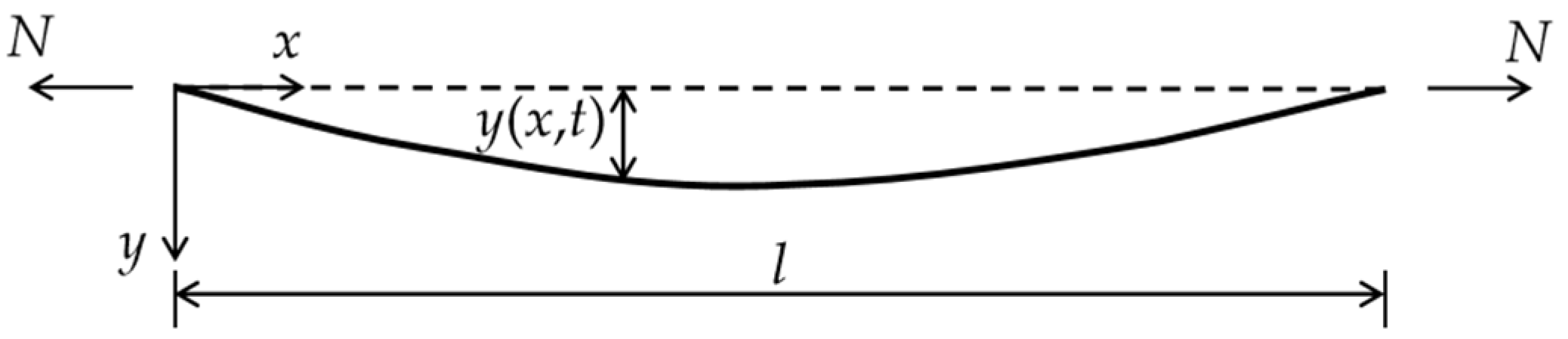
2.1. Equation of Cable Vibration

Considering the influence of sagging and cable force changes on vibration to be negligible, the fundamental differential equation of the cable-free vibration of a pre-stressed arch structure is given by:
2 x 2 ( E I d 2 y d x 2 ) + N 2 y x 2 + m 2 y t 2 = 0
where N denotes the cable tension (negative), EI denotes the cable bending stiffness, m denotes the unit mass of the cable, and l denotes the cable length. The vibration model of the cable is depicted in Figure 1.
In a constant cross-section cable, EI is constant. The separation of variables is used to decompose Equation (1), and the following differential equation is obtained:
T ¨ ( t ) + ω 2 T ( t ) = 0
Y ( 4 ) ( x ) + N E I Y ( x ) ω 2 m E I Y ( x ) = 0
Here, ω denotes the circular frequency. Equation (2) is a simple harmonic vibration equation, indicating that the cable performs a simple harmonic vibration in time. The general solution of Equation (3) is given by Equation (4), which is an expression for the cable vibration shape:
Y ( x ) = C 1 c h β x + C 2 s h β x + C 3 c o s γ x + C 4 s i n γ x
where,
γ = ( λ 4 + α 4 4 ) 1 / 2 + α 2 2 ;   β = ( λ 4 + α 4 4 ) 1 / 2 α 2 2 ;   α 2 = N E I ;   λ 4 = ω 2 m E I .
According to the cable boundary conditions, different cable vibration frequency equations can be calculated using Equation (4). The relationship between the cable force and frequency can be established as given below.
The boundary conditions of the hinged cable at both ends (Figure 2) are Y ( 0 ) = 0 , Y ( 0 ) = 0 , and Y ( l ) = 0 , Y ( l ) = 0 . The frequency equation can be obtained by substituting these boundary conditions into Equation (4):
sin γ l = 0
The roots of Equation (5) are γ n = n π l ( n = 1 , 2 , ) . Therefore, the frequency expression is as follows:
ω n = n 2 π 2 l 2 ( E I m N l 2 n 2 π 2 m ) ( n = 1 , 2 , )
Thus, the formula for calculating cable force, T, with both ends of the cable hinged, is as follows (here, fn denotes the Nth order frequency):
T = N = 4 m f n 2 l 2 n 2 E I n 2 π 2 l 2
Equation (7) is a commonly used cable force calculation formula based on the frequency method for a single-slender cable.
For cables with both ends fixed (Figure 3), Equation (8) can be calculated following the same method discussed above:
2 γ β ( 1 c h β l cos γ l ) + ( β 2 γ 2 ) sin γ l s h β l β = 0
For cables with one end fixed and the other hinged (Figure 4), Equation (9) can be similarly obtained:
γ s h β l cos γ l β c h β l s i n γ l = 0
Equations (8) and (9) are transcendental equations, so an explicit frequency expression cannot be obtained. Therefore, obtaining an exact expression for the cable force is difficult. However, solutions to Equations (8) and (9) can be approximated by constructing reasonable expressions. Take Equation (8) as an example.
The relationship between α l and λ l was established in Figure 5 using the numerical method. The curves show the two parameters’ relationship corresponding to each order of frequency, among which the fundamental one is our most concerned.
According to the curves calculated above, the curve formula is established as follows:
{ λ 1 2 ( 0.66418 l ) 2 = π π 2 ( α 2 ( 0.5 l ) 2 ) λ 2 2 ( 0.4 l ) 2 = π π 2 ( α 2 ( 0.349578 l ) 2 ) λ 3 2 ( 0.285713409 l ) 2 = π π 2 ( α 2 ( 0.25 l ) 2 ) λ 4 2 ( 0.222222241 l ) 2 = π π 2 ( α 2 ( 0.206778 l ) 2 ) λ 5 2 ( 0.181818178 l ) 2 = π π 2 ( α 2 ( 0.166667 l ) 2 )
It can be unified as:
λ n 2 ( b n l ) 2 = π π 2 ( α 2 ( a n l ) 2 )
Based on the analysis, anl is the calculated length of the fixed cable at both ends for the Nth order instability when the vibration frequency is zero. Further, bnl denotes the Nth mode equivalent half-wavelength of a cable fixed at both ends when the axial force is zero. Therefore, an and bn are considered to be length coefficients, whose values are listed in Table 1.
The comparison between the numerical solution curve of theoretical Equation (8) and the fitting Equation (11) is shown in Figure 6. It can be seen that Equation (11) has high fitting accuracy and is suitable for application.
According to Equation (11), the frequency expression is as follows:
ω n = π 2 ( b n l ) 2 ( E I m N ( a n l ) 2 m π 2 ) ( n = 1 , 2 , )
For cables with fixed ends, the following practical formula can be obtained:
T = 4 f n 2 m ( b n ) 4 l 2 ( a n ) 2 π 2 E I ( a n l ) 2

2.2. Theoretical Vibration Model of Continuous Multi-Span Cable Element

Given the vibrational complexity of continuous multi-span cables, a theoretical vibration model can be established using an inter-span cable as the analysis unit. The general cable unit model is depicted in Figure 7.
The following general boundary conditions were adopted. At one end, the bending moment and shear vibration frequency is ω, the amplitudes are M0 and Q0, the vibration period of rotation and deflection is ω, and the amplitudes are φ0 and Y0. By substituting the boundary conditions in Equation (4), the following equation is obtained:
Y ( 0 ) = Y 0 ,   Y ( 0 ) = φ 0 , E I Y ( 0 ) = M 0 , E I Y ( 0 ) = Q 0
Order β * = β l , γ * = γ l , i = E I / l denotes the line stiffness of the cable. From Equations (4) and (14), we obtain Equation (15). In the process of vibration, the vibration amplitudes of force P at both ends of the cable are as follows: MA, MB, which denote the bending moment amplitudes, and QA, QB, which denote the shear amplitudes. The vibration amplitudes of displacement, Δ, at both ends are as follows: φA, φB, which denote the angular displacement amplitudes, and YA, YB, which denote the vertical displacement amplitudes.
{ M A = i ( D φ A + E φ B + F Y A l G Y B l ) M B = i ( E φ A + D φ B + G Y A l F Y B l ) Q A = i l ( H φ A + G φ B + K Y A l R Y B l ) Q B = i l ( G φ A + H φ B + R Y A l K Y B l )
where,
D = 1 ( β * 2 + γ * 2 ) ( γ * sin β * c h γ * β * cos β * s h γ * ) ; E = 1 ( β * 2 + γ * 2 ) ( β * s h γ * γ * sin β * ) ; F = 1 β * γ * [ 2 β * γ * sin β * s h γ * ( γ * 2 β * 2 ) ( 1 cos β * c h γ * ) ] ; G = 1 β * γ * ( β * 2 + γ * 2 ) ( c h γ * cos β * ) ; H = 1 [ β * γ * ( γ * 2 β * 2 ) ( 1 cos β * c h γ * ) + ( γ * 4 + β * 4 ) sin β * s h γ * ] ; K = 1 β * γ * ( β * 2 + γ * 2 ) ( β * c h γ * sin β * + γ * s h γ * cos β * ) R = 1 β * γ * ( β * 2 + γ * 2 ) ( β * sin β * + γ * s h γ * ) = 2 β * γ * ( 1 cos β * c h γ * ) + ( γ * 2 β * 2 ) s h γ * sin β *   ( Π     0 )
When Π = 0, the vibration characteristic equation of a cable fixed at both ends can be expressed in the following general form:
{ K 11 Δ 1 + K 12 Δ 2 + K 13 Δ 3 + K 14 Δ 4 = P 1 K 21 Δ 1 + K 22 Δ 2 + K 23 Δ 3 + K 24 Δ 4 = P 2 K 31 Δ 1 + K 32 Δ 2 + K 33 Δ 3 + K 34 Δ 4 = P 3 K 41 Δ 1 + K 42 Δ 2 + K 43 Δ 3 + K 44 Δ 4 = P 4
where,
Δ 1 = φ A ;   Δ 2 = φ B ;   Δ 3 = Y A ;   Δ 4 = Y B ; P 1 = M A ;   P 2 = M B ;   P 3 = Q A ;   P 4 = Q B ; K 11 = K 22 = i D ;   K 21 = K 12 = i E ; K 13 = K 24 = i l F ;   K 14 = K 23 = K 32 = K 41 = i l G ; K 31 = K 42 = i l H ;   K 33 = K 44 = i l 2 K ; K 34 = K 43 = i l 2 R .
When the cable force T = 0, Equation (16) degenerates into the vibration equation of a frame or beam without axial force.

2.3. Multi-Frequency Fitting Method for Continuous Multi-Span Cables

A multi-span continuous cable vibration model was established, as depicted in Figure 8. The established vibration equation is:
{ ( Z 11 + k 1 ) Δ 1 + Z 12 Δ 2 + Z 13 Δ 3 + Z 1 n Δ n = 0 , Z 21 Δ 1 + ( Z 22 + k 2 ) Δ 2 + Z 23 Δ 3 + Z 2 n Δ n = 0 , Z 31 Δ 1 + Z 32 Δ 2 + ( Z 33 + k 3 ) Δ 3 + Z 3 n Δ n = 0 , Z n 1 Δ 1 + Z n 2 Δ 2 + K n 3 Δ 3 + ( Z n n + k n ) Δ n = 0 ,
where the non-zero elements of the stiffness coefficient are given by:
Z 11 = K 11 ( 1 ) ; Z 12 = K 12 ( 1 ) ;   Z 21 = K 21 ( 1 ) ;   Z 22 = K 22 ( 1 ) + K 11 ( 2 ) ; Z 23 = K 12 ( 2 )   ;   Z 32 = K 21 ( 2 ) ;   Z 33 = K 22 ( 2 ) + K 11 ( 3 ) ; Z ( n 1 ) n = K 12 ( n 1 ) ;   Z n ( n 1 ) = K 21 ( n 1 )   ;   Z n n = K 22 ( n 1 ) + K 11 n .
Here, k1, k2, …, and kn are the unknown constraints, and the corresponding frequency characteristic equation is given by:
| Z 11 + k 1                   Z 12                                         0               Z 21               Z 22 + k 2                               0                                                                                         0                               0                                 0                                 Z n n + k n | = 0 .
Equation (18) can be expressed as:
f ( E I , m , ω i , T , k 1 , k 2 , , k n ) = 0                 ( i = 1 , 2 , 3 ) .
The system (as given in Equation (19)) has n + 1 unknown parameters T and ki. The multi-span cable characteristic parameters can be identified using the multi-frequency method. If the detected frequency order s is greater than the number of unknown parameters n + 1, all unknown parameters can be accurately identified. Theoretically, an infinite number of frequencies satisfy the frequency equation (Equation (18)). While obtaining the cable force from a set of frequency values, distortion may occur due to order dislocation. However, the frequency error will cause deviations of the calculated cable force from the real cable force. Thus, the distorted cable force can be preliminarily ruled out by the cable force.

3. Experimental Verification of Cable Force Identification Theory

3.1. Multi-Frequency Fitting Method for Cable Force Identification and Its Verification

For multi-span cables, cable forces can be effectively identified by detecting the multi-order vibration frequencies using the multi-frequency fitting method. The procedure is as follows:
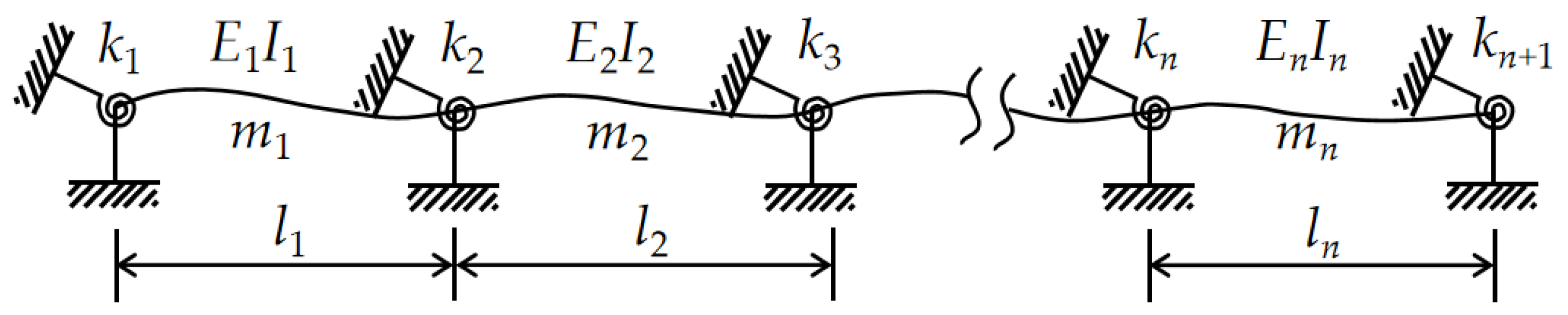
  • First, a multi-span cable vibration model is established. The characteristic equation of a cable supported by brace struts, with m spans and n unknown stiffness constraints, is given by:
    f i ( E I ,   M ,   ω i ,   T ,   l 1 ,   l 2 ,   ,   l m ,   k 1 ,   k 2 ,   ,   k n ) = 0 ,                 ( i = 1 ,   2 ,   3 ) .
  • The N + 1 natural frequencies, ωi, are obtained from the experimental data. N equations for the cable force T and n stiffness constraints are established. The optimization algorithm model is designed with the following optimization objective function:
    f o b j = M i n { | f ( E I ,   m , ω i , T , k 1 , k 2 , , k n ) | } .
  • To calculate the cable force T, an unconstrained optimization algorithm is adopted to select the initial cable force parameters. The values of the n + 1 unknown parameters are calculated via regression for the optimization objective function.
  • The accuracy of the obtained cable force value is verified, and conclusions are drawn based on the calculation.

3.1.1. Single-Cable Test—Phase I

Data analysis was performed using the specific data acquisition and analysis software of the DASP-V10 engineering edition produced by the China Orient Institute of Noise and Vibration (INV). Lance LC0116T-2 low-frequency ICP piezoelectric uniaxial acceleration sensors were used for the test. A Lance CBook2000-P type specific dynamic acquisition instrument was used as the acquisition model. The bracket structure of the model used in the test is illustrated in Figure 9 and Figure 10. The linear density of the cable was 1.4235 kg/m, and the bending modulus of the 15.2 mm-diameter steel strand was 526.4 N·m2. The continuous cable comprised four spans, each with a length of 2 m. According to the test conditions, the cable boundary constraint stiffness of the multi-frequency cable force identification model was taken to be zero. The self-spectral analysis of the acceleration response is depicted in Figure 11, and the obtained frequency and cable force values are listed in Table 2.

3.1.2. Cable-Stayed Structure Test—Phase II

A cable force identification test platform was adopted using a large-span spatial structure. It comprised 158 bolt-ball nodes and 560 rods, as shown in Figure 12. The platform was a grid structure with a length of 9 m, width of 6 m, and height of 0.8 m. The platform had the characteristics of good stability, light weight, flexibility, and convenient installation, and could simulate various spatial-structure types.
IEPE-INV9822 acceleration sensors were used as the dynamic measuring equipment in the experiment. The signal acquisition equipment was an INV3065N2 data acquisition system. Specific data acquisition and analysis software of the DASP-V11 engineering edition produced by the China Orient Institute of Noise and Vibration were utilized for the data analysis. The cable-stayed structural model is depicted in Figure 13 and Figure 14. The linear density of the cable was 1.4235 kg/m, and the bending modulus of the steel strand was 220.8 N·m2. The total length of the cable-stayed structure was 7.2 m, which was divided into two sections (3.6 m each) by the middle brace strut. Based on the test conditions, the boundaries of the cable were considered hinged. The self-spectral analysis of the acceleration response is depicted in Figure 15, and the results of frequency detection and cable force identification are listed in Table 3.
The results show that the cable force was determined with a relative error of 8%.

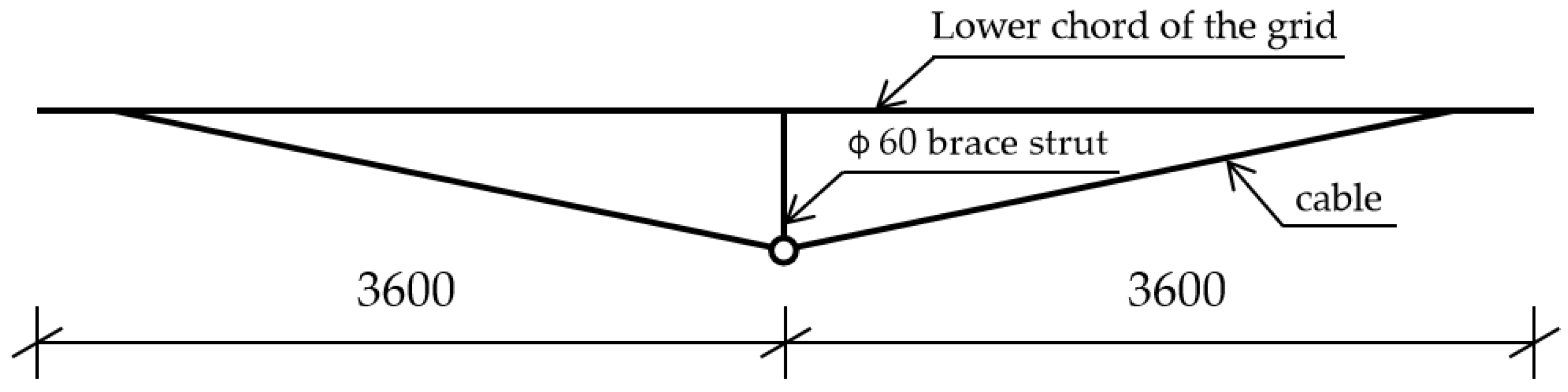
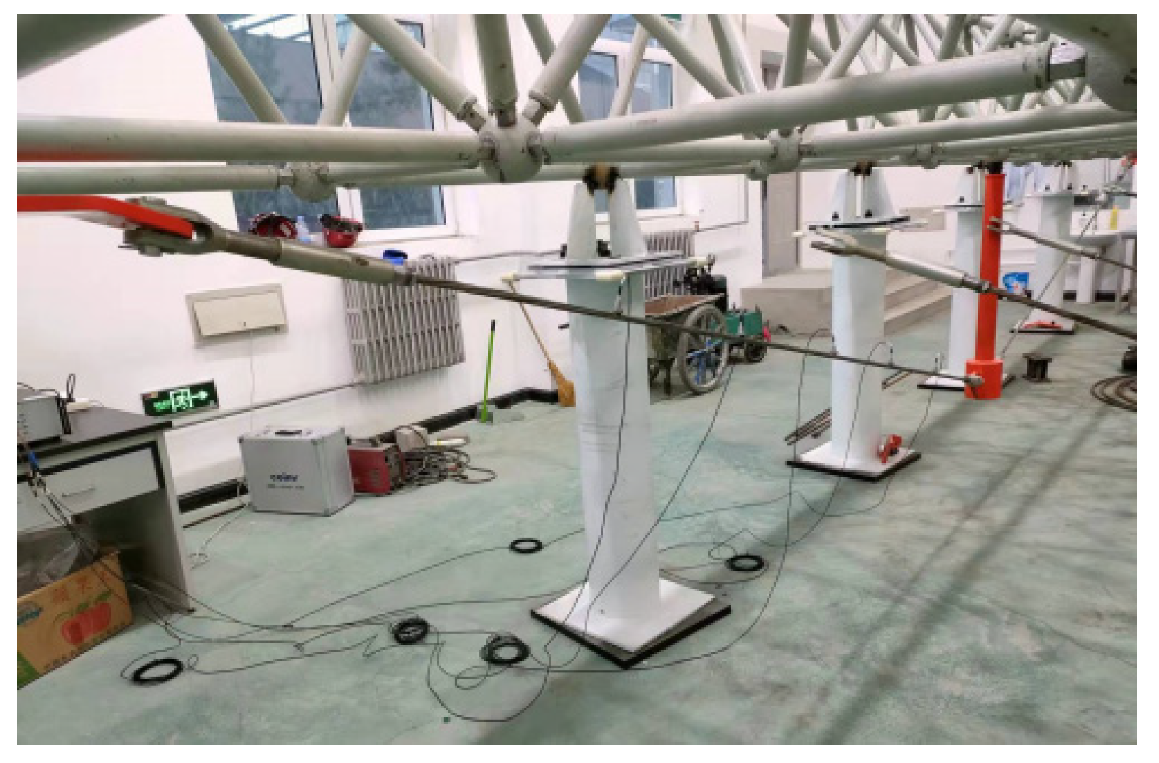
3.1.3. Unidirectional String Structure Test

The unidirectional string structure used in the experiments is depicted in Figure 16. The lengths of its spans were 5441.7, 7566.7, 7566.7, 7566.7, 7566.7, and 5441.7 mm. The linear density of the cable was 18.7 kg/m, and the bending modulus was 139.0208 kN·m2. The frequency detection and multi-frequency cable force identification results are listed in Table 4.

3.1.4. Bidirectional String Structure Test

The bidirectional string structure used in the experiments is depicted in Figure 17. The structure comprised seven horizontal and six vertical cables. Cables in both directions passed through the lower part of the brace struts and were connected to the upper and lower ends of the inner and outer brace struts. The lengths of the spans tested were 2.256, 2.716, 2.703, 2.700, 2.703, 2.716, and 2.256 m. The linear density of the cable was 3.28 kg/m, and the bending modulus was 321.00 N·m2. The results of frequency detection and multi-frequency cable force identification are listed in Table 5.
The analysis of the test results revealed that the cable force value obtained is in good agreement with the actual cable force value.

4. Realization and Development of Cable Safety Monitoring System

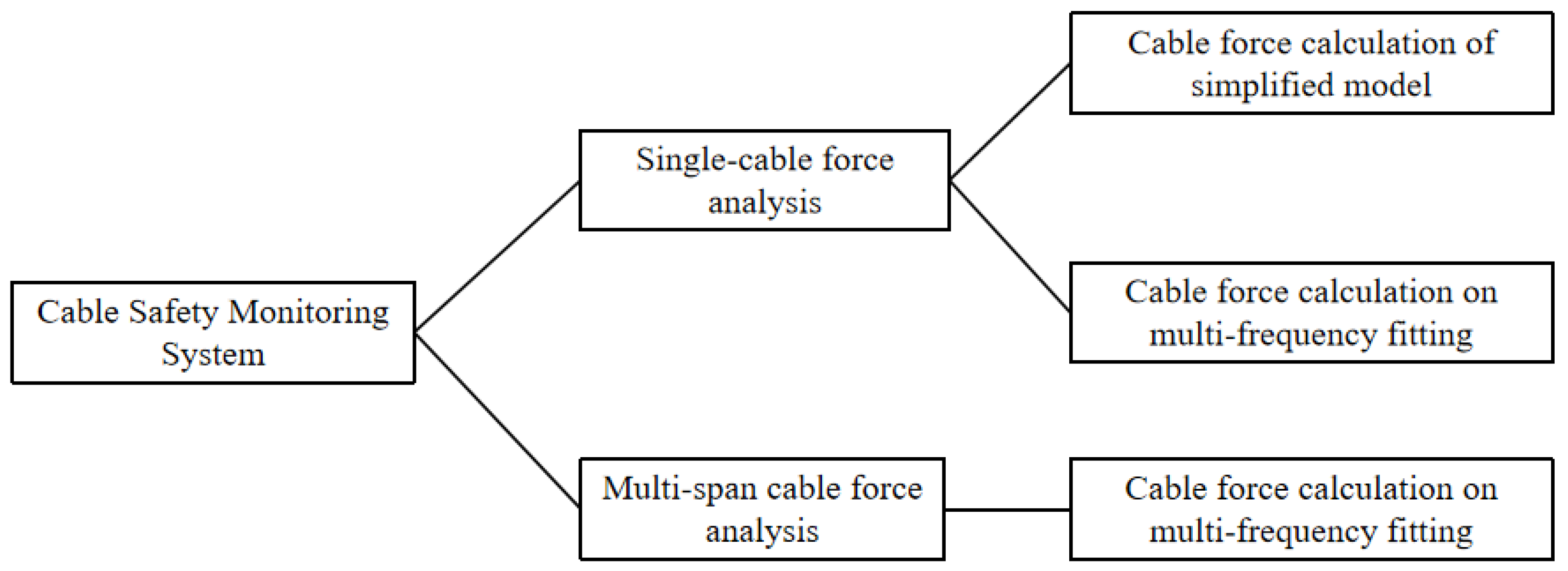
4.1. System Function Design

The cable safety monitoring system can be used for efficiently monitoring and controlling the cable force and assessing the reliability of pre-stressed cable structures during construction and operation. The primary components of the system are depicted in Figure 18.

4.2. System Hardware Integration

The system’s hardware used for vibration signal acquisition comprised sensors, signal acquisition equipment, data processing tools, and excitation equipment.
  • Sensors: Lance LC0116T-2 low-frequency ICP piezoelectric uniaxial acceleration sensors were used in this paper. The technical indices of the sensor are listed in Table 6.
  • Signal acquisition equipment, the Cm4016 conditioning module for sensors, was used. The acquisition module was a Lance CBook 2000-P specific dynamic acquisition instrument capable of accepting 16-channel parallel input acquisition simultaneously with an effective resolution of 16 bit. A cassette acquisition device was used as an intelligent signal analyzer, which can be used with computers and software, to realize the full automation of large-capacity multichannel data acquisition, display, oscilloscope measurements, readings, waveform analysis, spectrum analysis, digital filtering, integral and differential, calculation of waveform analysis, storage, printing, copying, etc.
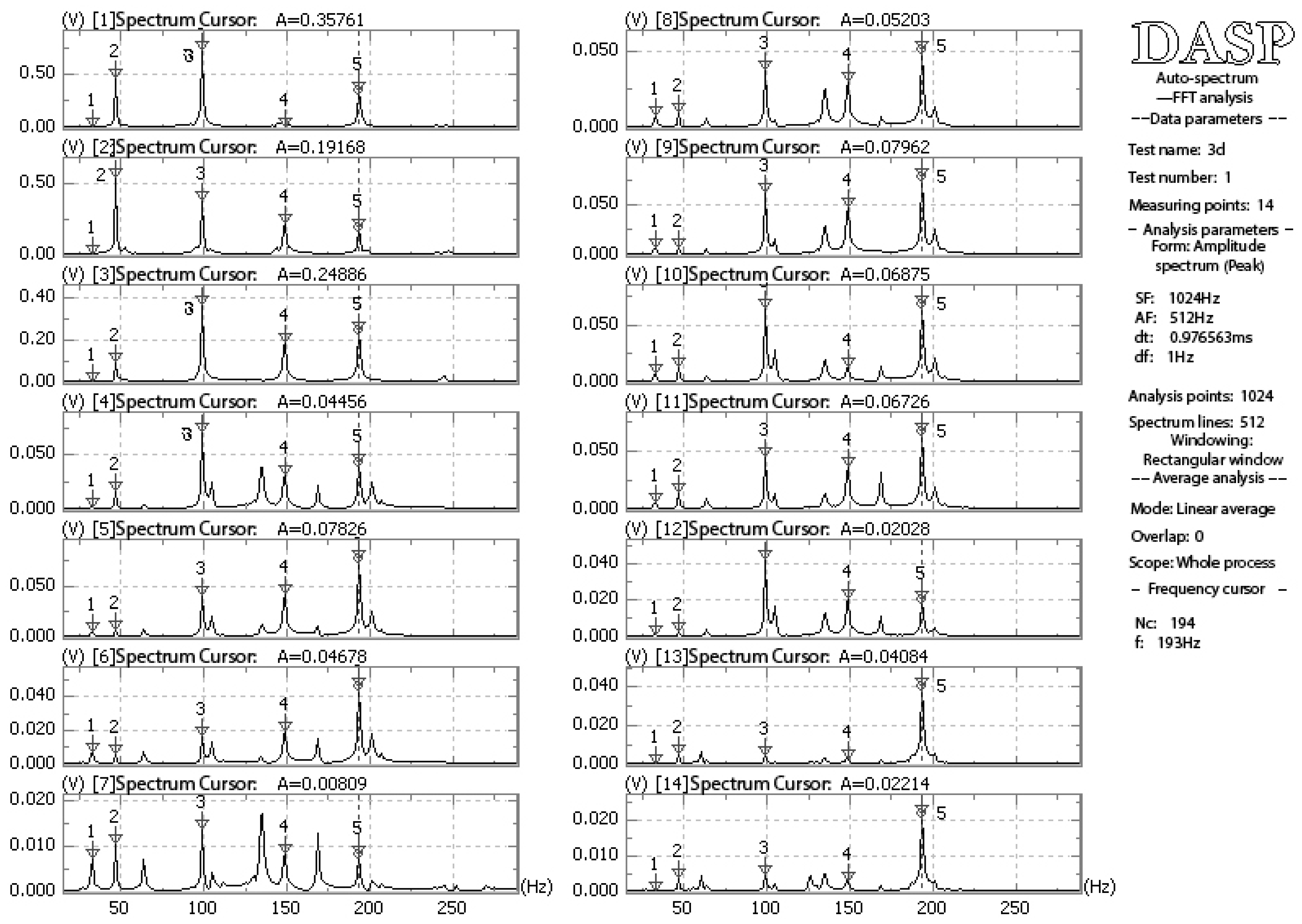
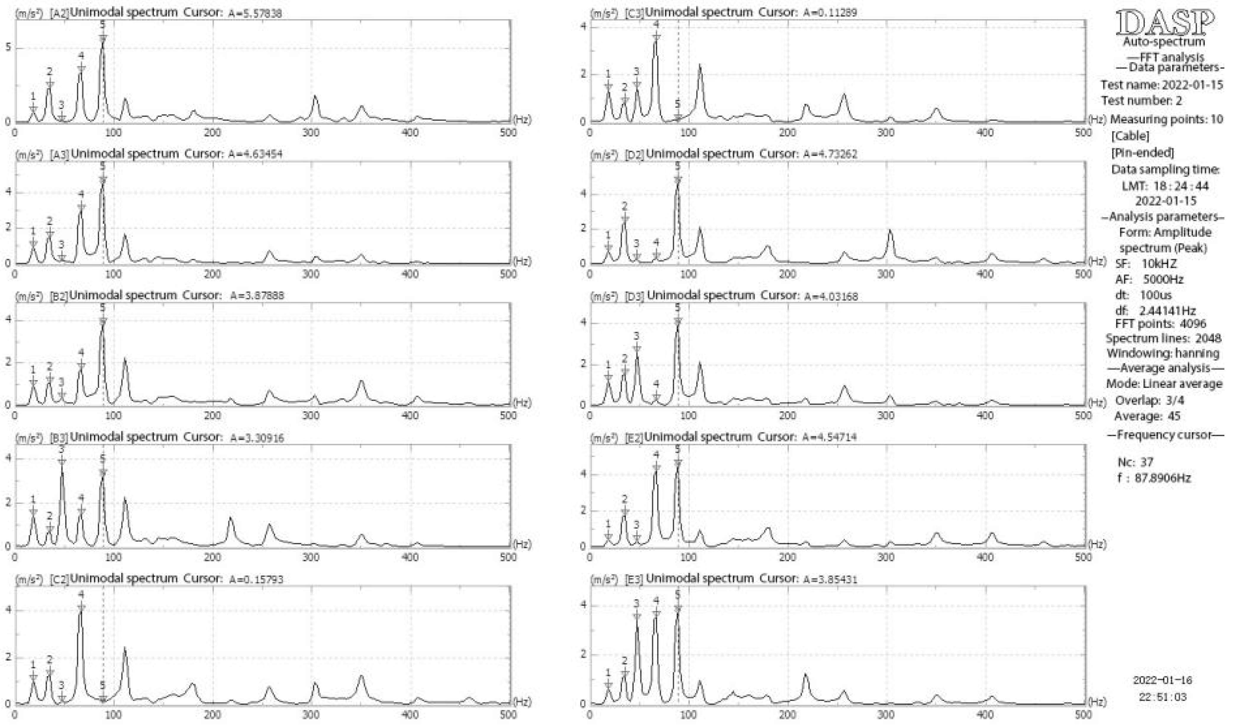
  • The specific data acquisition and analysis software of the DASP-V10 engineering edition produced by the China Orient Institute of Noise and Vibration was utilized for the data analysis. Its design functions included large-capacity signal oscillograph sampling and the analyses of multi-trace time domain, multi-trace self-spectrum, autocorrelation, cross-correlation, cross-power spectrum, and transfer function.

4.3. Visual Software System

The visual software system was originally developed with C# based on the multi-frequency fitting method and cable force calculation formula studied in this paper. The cable safety monitoring system consisted of single- and multi-span cable force analysis modules, as depicted in Figure 19.
The functional modules of the software included cable force calculation for the simplified model, single-cable force calculation with an arbitrary boundary, and multi-span cable force calculation.
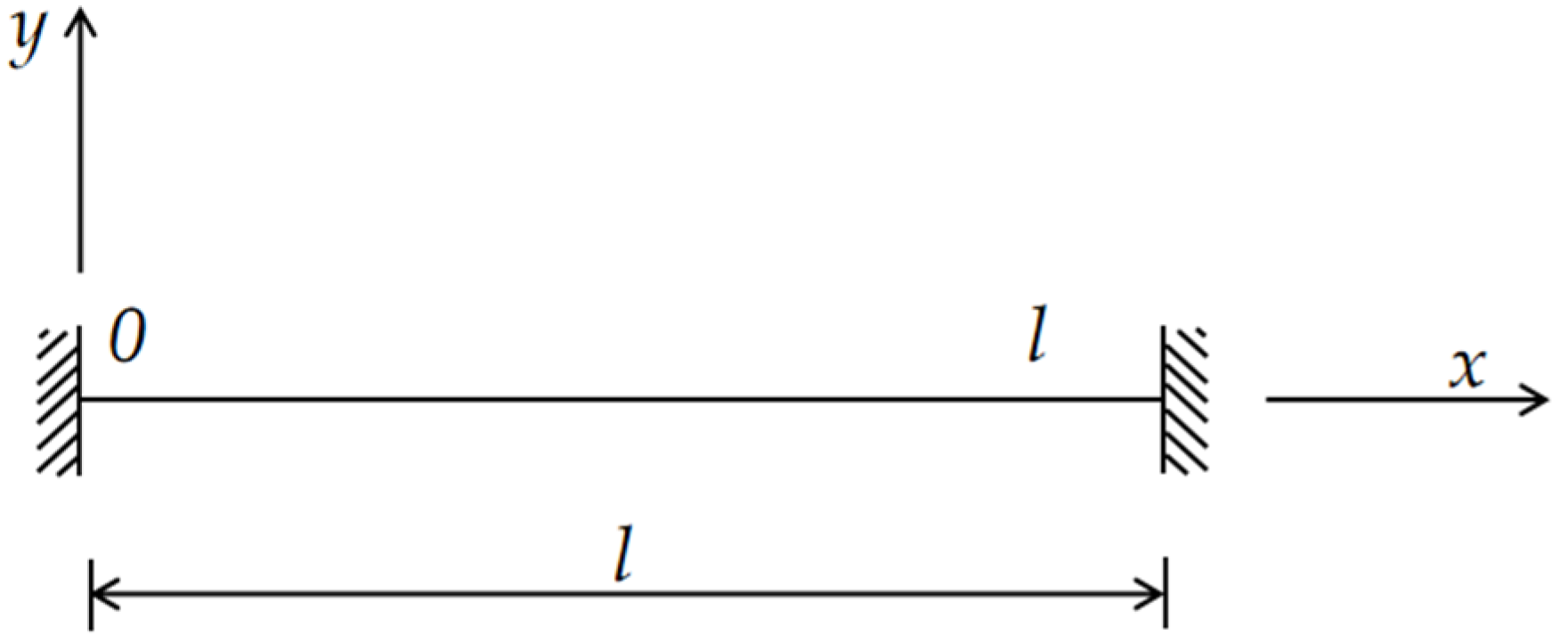
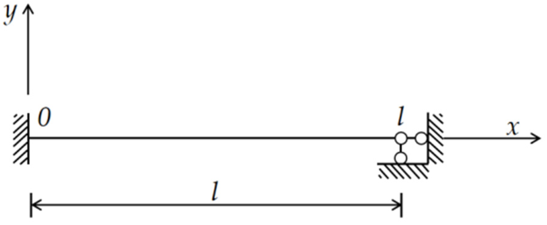
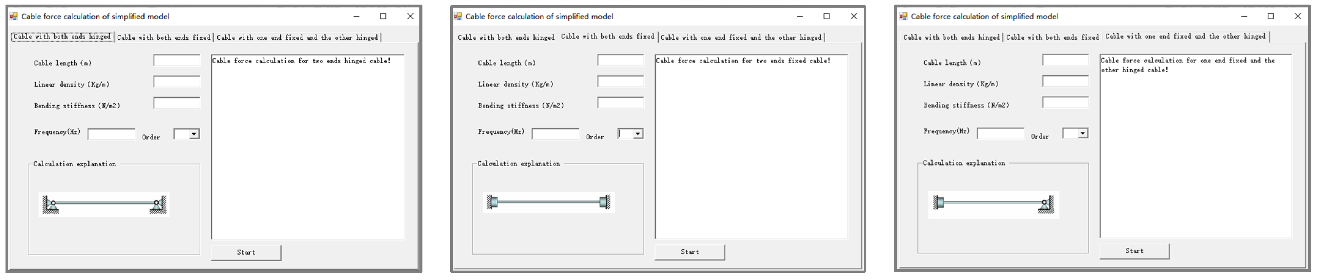
  • The cable force calculation for the simplified model included three types of specific boundaries: cables with both ends hinged, one end fixed and the other hinged, and both ends fixed, as illustrated in Figure 20.
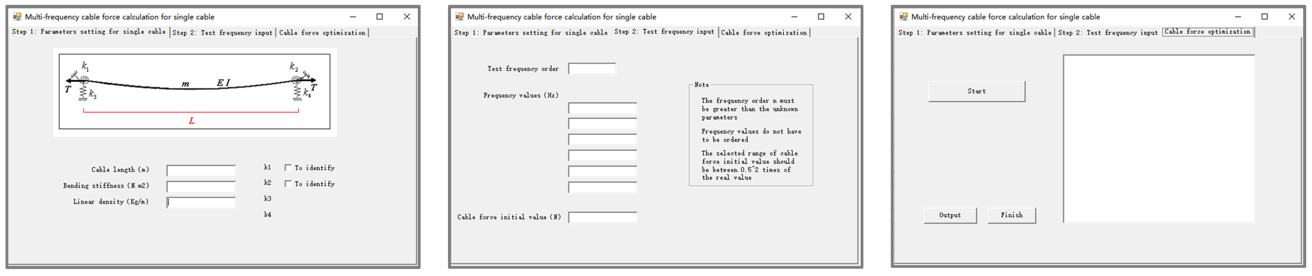
  • For single-cable force calculation with an arbitrary boundary, the cable force and constraint stiffness were calculated according to the input basic cable parameters and multi-order frequencies obtained by the spectrum analysis, as illustrated in Figure 21.
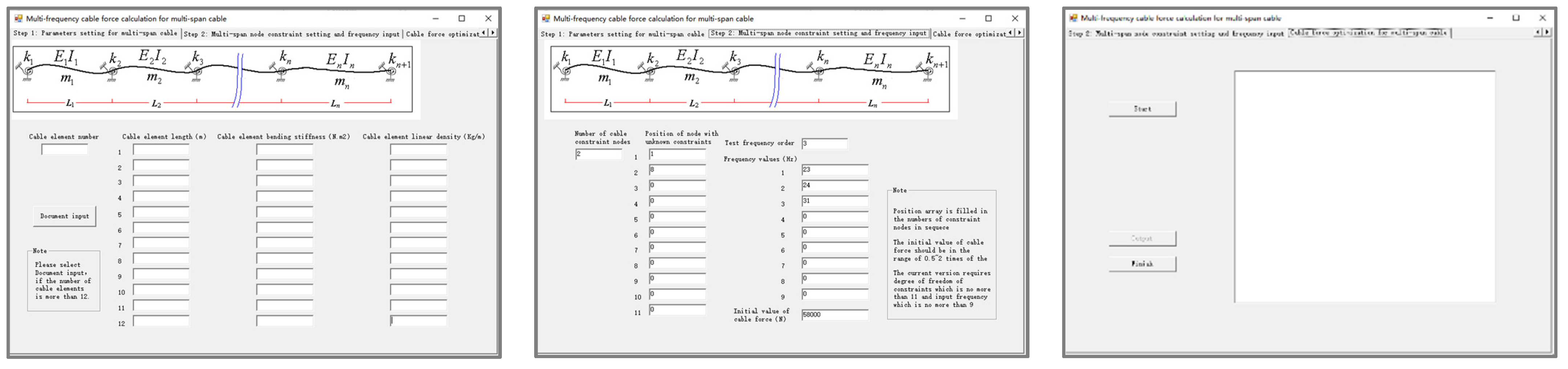
  • For the multi-span cable force calculation, the multi-frequency fitting method was used to calculate the cable force and the cable stiffness constraints according to the input cable parameters and multi-order frequencies, as illustrated in Figure 22.

5. Conclusions

Based on the multi-frequency fitting method, this study proposed a cable force identification approach for pre-stressed steel structures. The vibration model and characteristic equations of short and coarse cables were established based on the vibration theory. The corresponding relationship between cable force and frequency was also established. For cables with arbitrary elastic boundary conditions, the cable forces were determined by measuring multi-frequencies with no less than a number of unknown parameters. Considering the bending stiffness, the established vibration frequency transcendence equation was optimized and solved based on the unconstrained optimization algorithm. The proposed method has strong adaptability and reliability. The traditional single-cable force calculation method poses difficulty in the effective analysis of the multi-span cable force, experimentally, and the proposed method addresses this problem. This method can restrict the relative error of cable force identification within 8%, which meets the precision requirement of engineering applications. The designed and developed cable force safety monitoring software can easily determine the tension of single-span and multi-span cables through a simplified model and multi-frequency fitting.

Author Contributions

Conceptualization, J.Q.; formal analysis, Z.J.; funding acquisition, J.Q. and Z.J.; investigation, F.L.; methodology, J.Q.; resources, F.L. and Q.Z.; software, Q.Z.; writing—original draft, Z.J. All authors have read and agreed to the published version of the manuscript.

Funding

This research was funded by the Opening Funds of the State Key Laboratory of Building Safety and Built Environment and the National Engineering Research Center of Building Technology, grant number: BSBE2021-10, and the Fundamental Research Funds for the Central Universities, China, grant number: 3142020019.

Conflicts of Interest

The authors declare no conflict of interest.

References

  1. Mehrabi, A.B. In-service evaluation of cable-stayed bridges, overview of available methods and findings. J. Bridge Eng. 2006, 11, 716–724. [Google Scholar] [CrossRef]
  2. Kim, S.W.; Kim, N.S. Dynamic characteristics of suspension bridge hanger cables using digital image processing. NDT E Int. 2013, 59, 25–33. [Google Scholar] [CrossRef]
  3. Xue, S.L.; Shen, R.L. Real time cable force identification by short time sparse time domain algorithm with half wave. Measurement 2020, 152, 107355. [Google Scholar] [CrossRef]
  4. Nazarian, E.; Ansari, F.; Zhang, X.; Taylor, T. Detection of tension loss in cables of cable-stayed bridges by distributed monitoring of bridge deck strains. J. Struct. Eng. 2016, 142, 04016018. [Google Scholar] [CrossRef]
  5. Zhang, L.X.; Qiu, G.Y.; Chen, Z.S. Structural health monitoring methods of cables in cable-stayed bridge: A review. Measurement 2021, 168, 108343. [Google Scholar] [CrossRef]
  6. Qin, J.; Gao, Z.G.; Qian, Y.X.; Wang, F. Theory and Technology of Cable Force Test for Prestressed Steel Structure; China Architecture & Building Press: Beijing, China, 2010. (In Chinese) [Google Scholar]
  7. Rebelo, C.; Júlio, E.; Varum, H.; Costa, A. Cable tensioning control and modal identification of a circular cable-stayed footbridge. Exp. Tech. 2010, 34, 62–68. [Google Scholar] [CrossRef]
  8. Bao, Y.; Shi, Z.; Beck, J.L.; Li, H.; Hou, T.Y. Identification of time-varying cable tension forces based on adaptive sparse time-frequency analysis of cable vibrations. Struct. Control Health Monit. 2017, 24, e1889. [Google Scholar] [CrossRef]
  9. Pacitti, A.; Peigney, M.; Bourquin, F.; Lacarbonara, W. Experimental data based cable tension identification via nonlinear static inverse problem. Procedia Eng. 2017, 199, 453–458. [Google Scholar] [CrossRef]
  10. Geier, R.; De Roeck, G.; Flesch, R. Accurate cable force determination using ambient vibration measurements. Struct. Infrastruct. Eng. 2006, 2, 43–52. [Google Scholar] [CrossRef]
  11. Yu, Z.R.; Shao, S.; Liu, N.; Zhou, Z.; Feng, L.; Du, P.; Tang, J. Cable tension identification based on near field radiated acoustic pressure signal. Measurement 2021, 178, 109354. [Google Scholar] [CrossRef]
  12. Yao, Y.D.; Yan, M.; Bao, Y. Measurement of cable forces for automated monitoring of engineering structures using fiber optic sensors: A review. Autom. Constr. 2021, 126, 103687. [Google Scholar] [CrossRef]
  13. Zheng, R.; Liu, L.; Zhao, X.; Chen, Z.; Zhang, C.; Hua, X. Investigation of measurability and reliability of adhesive-bonded built-in fiber Bragg grating sensors on steel wire for bridge cable force monitoring. Measurement 2018, 129, 349–357. [Google Scholar] [CrossRef]
  14. Li, X.X.; Ren, W.X.; Bi, K.M. FBG force-testing ring for bridge cable force monitoring and temperature compensation. Sens. Actuators A. 2015, 223, 105–113. [Google Scholar] [CrossRef]
  15. Hu, D.; Guo, Y.; Chen, X.; Zhang, C. Cable force health monitoring of Tongwamen bridge based on fiber Bragg grating. Appl. Sci. 2017, 7, 384. [Google Scholar] [CrossRef] [Green Version]
  16. Feng, D.; Scarangello, T.; Feng, M.Q.; Ye, Q. Cable tension force estimate using novel noncontact vision-based sensor. Measurement 2017, 99, 44–52. [Google Scholar] [CrossRef]
  17. Gentile, C.; Cabboi, A. Vibration-based structural health monitoring of stay cables by microwave remote sensing. Smart Struct. Syst. 2015, 16, 263–280. [Google Scholar] [CrossRef]
  18. Liu, Y.; Xie, J.Z.; Tafsirojjaman, T.; Yue, Q.; Tan, C.; Che, G. CFRP lamella stay-cable and its force measurement based on microwave radar. Case Stud. Constr. Mater. 2022, 16, e00824. [Google Scholar] [CrossRef]
  19. Chen, C.C.; Wu, W.H.; Tseng, H.Z.; Chen, C.; Lai, G. Application of digital photogrammetry techniques in identifying the mode shape ratios of stay cables with multiple camcorders. Measurement 2015, 75, 134–146. [Google Scholar] [CrossRef]
  20. Du, W.K.; Lei, D.; Bai, P.X.; Zhu, F.; Huang, Z. Dynamic measurement of stay-cable force using digital image techniques. Measurement 2020, 151, 107211. [Google Scholar] [CrossRef]
  21. Jo, H.C.; Kim, S.H.; Lee, J.; Sohn, H.; Lim, Y.M. Sag-based cable tension force evaluation of cable-stayed bridges using multiple digital images. Measurement 2021, 186, 110053. [Google Scholar] [CrossRef]
  22. Russell, J.C.; Lardner, T.J. Experimental determination of frequencies and tension for elastic cables. J. Eng. Mech. 1998, 124, 1067–1072. [Google Scholar] [CrossRef]
  23. Irvine, H.M. Cable Structures; The MIT Press: Cambridge, MA, USA, 1981. [Google Scholar]
  24. Fang, Z.; Wang, J.Q. Practical formula for cable tension estimation by vibration method. J. Bridge Eng. 2012, 17, 161–164. [Google Scholar] [CrossRef]
  25. Kim, B.H.; Park, T. Estimation of cable tension force using the frequency-based system identification method. J. Sound Vib. 2007, 304, 660–676. [Google Scholar] [CrossRef]
  26. Wang, J.; Liu, W.Q.; Wang, L.; Han, X. Estimation of main cable tension force of suspension bridges based on ambient vibration frequency measurements. Struct. Eng. Mech. 2015, 56, 939–957. [Google Scholar] [CrossRef]
  27. Ceballos, M.A.; Prato, C.A. Determination of the axial force on stay cables accounting for their bending stiffness and rotational end restraints by free vibration tests. J. Sound Vib. 2008, 317, 127–141. [Google Scholar] [CrossRef]
  28. Nam, H.; Nghia, N.T. Estimation of cable tension using measured natural frequencies. Procedia Eng. 2011, 14, 1510–1517. [Google Scholar] [CrossRef] [Green Version]
  29. Chen, C.C.; Wu, W.H.; Leu, M.R.; Lai, G. Tension determination of stay cable or external tendon with complicated constraints using multiple vibration measurements. Measurement 2016, 86, 182–195. [Google Scholar] [CrossRef]
  30. Chen, C.C.; Wu, W.H.; Chen, S.Y.; Lai, G. A novel tension estimation approach for elastic cables by elimination of complex boundary condition effects employing mode shape functions. Eng. Struct. 2018, 166, 152–166. [Google Scholar] [CrossRef]
  31. Yan, B.F.; Yu, J.; Soliman, M. Estimation of cable tension force independent of complex boundary conditions. J. Eng. Mech. 2015, 141. [Google Scholar] [CrossRef]
  32. Yan, B.F.; Chen, W.B.; Yu, J.Y.; Jiang, X. Mode shape-aided tension force estimation of cable with arbitrary boundary conditions. J. Sound Vib. 2019, 440, 315–331. [Google Scholar] [CrossRef]
  33. Ma, L. A highly precise frequency-based method for estimating the tension of an inclined cable with unknown boundary conditions. J. Sound Vib. 2017, 409, 65–80. [Google Scholar] [CrossRef]
  34. Ma, L.; Xu, H.; Munkhbaatar, T.; Li, S. An accurate frequency-based method for identifying cable tension while considering environmental temperature variation. J. Sound Vib. 2021, 490, 1–16. [Google Scholar] [CrossRef]
  35. Zhang, S.H.; Shen, R.L.; Wang, Y.; De Roeck, G.; Lombaert, G.; Dai, K. A two-step methodology for cable force identification. J. Sound Vib. 2020, 472, 115201. [Google Scholar] [CrossRef]
  36. Schlune, H.; PloS, M.; Gylltoft, K. Improved bridge evaluation through finite element model updating using static and dynamic measurements. Eng. Struct. 2009, 31, 1477–1485. [Google Scholar] [CrossRef]
  37. Wang, R.H.; Gan, Q.; Huang, Y.H.; Ma, H. Estimation of tension in cables with intermediate elastic supports using finite-element method. J. Bridge Eng. 2011, 16, 675–678. [Google Scholar] [CrossRef]
  38. Liao, W.Y.; Ni, Y.Q.; Zheng, G. Tension force and structural parameter identification of bridge cables. Adv. Struct. Eng. 2012, 15, 983–995. [Google Scholar] [CrossRef]
  39. Mehrabi, A.B.; Telang, N.M.; Ghara, H.; Fossier, P. Health monitoring of cable-stayed bridges-A case study. Structures 2004, 1–8. [Google Scholar] [CrossRef]
  40. Pan, H.; Azimi, M.; Yan, F.; Lin, Z. Time-frequency-based data-driven structural diagnosis and damage detection for cable-stayed bridges. J. Bridge Eng. 2018, 23, 04018033. [Google Scholar] [CrossRef]
  41. Huynh, T.C.; Park, J.H.; Kim, J.T. Structural identification of cable-stayed bridge under back-to-back typhoons by wireless vibration monitoring. Measurement 2016, 88, 385–401. [Google Scholar] [CrossRef]
Figure 1. Cable vibration analysis model.
Buildings 12 01689 g001
Figure 2. Cable with both ends hinged.
Buildings 12 01689 g002
Figure 3. Cable with both ends fixed.
Buildings 12 01689 g003
Figure 4. Cable with one end fixed and the other hinged.
Buildings 12 01689 g004
Figure 5. The relationship between ( α l )2 and ( λ l )2.
Buildings 12 01689 g005
Figure 6. Equation (11) is numerically fitted to the theoretical equation.
Buildings 12 01689 g006
Figure 7. Cable vibration analysis unit.
Buildings 12 01689 g007
Figure 8. Multi-span cable model.
Buildings 12 01689 g008
Figure 9. Design of the bracket structure model used in the test.
Buildings 12 01689 g009
Figure 10. Bracket structure model used for the experiment.
Buildings 12 01689 g010
Figure 11. Self-spectral analysis of the acceleration response.
Buildings 12 01689 g011
Figure 12. (a) Large-span space structure cable force identification test platform. (b) Cable laying.
Buildings 12 01689 g012
Figure 13. Design of the cable-stayed structure model used in the test.
Buildings 12 01689 g013
Figure 14. Cable frequency test photograph of the cable-stayed structure.
Buildings 12 01689 g014
Figure 15. Self-spectral analysis of the acceleration response.
Buildings 12 01689 g015
Figure 16. (a) Unidirectional string structure used in the experiment. (b) Frequency test of the unidirectional string structure.
Buildings 12 01689 g016
Figure 17. (a) Bidirectional string structure used in the experiment. (b) Frequency test of the bidirectional string structure.
Buildings 12 01689 g017
Figure 18. Functional scheme of the cable safety monitoring system.
Buildings 12 01689 g018
Figure 19. Software structure organization.
Buildings 12 01689 g019
Figure 20. Cable force calculation in the simplified model.
Buildings 12 01689 g020
Figure 21. Single-cable force calculation with an arbitrary boundary.
Buildings 12 01689 g021
Figure 22. Multi-span cable force calculation.
Buildings 12 01689 g022
Table 1. Calculation of the length coefficients.
Order: nanbn
10.50.664178761
20.3495780.40003957
30.250.285713409
40.2067780.222222241
50.1666670.181818178
Table 2. Results of frequency detection and cable force identification.
Calculation TimesInitial Values of Optimization (kN)Identified Cable Force Values (kN)Actual Tension Value (kN)
189.81989.72590
280.00089.725
3100.00089.725
Detection frequency (Hz): f (1) = 32.25; f (2) = 46.5; f (3) = 63.25; f (4) = 99.25; f (5) = 149.5.
Table 3. Results of frequency detection and cable force calculation of a cable-stayed structure.
Frequency Order Identified Cable Force Values (kN)Identified Cable Force Average Values (kN)Actual Cable Force Value (kN)
121.385 18.87220.35
220.881
316.132
417.355
518.606
Detection frequency (Hz): f (1) = 17.0898; f (2) = 34.1797; f (3) = 46.3867; f (4) = 65.9180; f (5) = 87.8906.
Table 4. Results of frequency detection and multi-frequency fitting cable force optimization of a unidirectional string structure.
Calculation TimesInitial Values of Optimization (kN)Constraint Stiffness of the Left Support (kN·m2)Constraint Stiffness of the Right Support (kN·m2)Identified Cable Force Values (kN)Identification Stiffness of Left Support (kN·m2)Identification Stiffness of Right Support (kN·m2)Actual Tension Value (kN)
1415.5341.01.0287.815151.41292.340300
2322.9561.01.0286.748147.33643.374
Detection frequency (Hz): f (1) = 9.00; f (2) = 10.135; f (3) = 12.00; f (4) = 13.56.
Table 5. Results of frequency detection and multi-frequency fitting cable force optimization of a bidirectional string structure.
Calculation TimesInitial Values of Optimization (kN)Constraint Stiffness of the Left Support (kN·m2)Constraint Stiffness of the Right Support (kN·m2)Identified Cable Force Values (kN)Identification Stiffness of Left Support (kN·m2)Identification Stiffness of Right Support (kN·m2)Actual Tension Value (kN)
150.7681.01.054.3543.79763.18755
255.3171.01.055.3863.85766.026
Detection frequency (Hz): f (1) = 23; f (2) = 24; f (3) = 31.
Table 6. Parameters of the sensor.
Technical IndexesIndex ValueTechnical Indexes Index Value
Response frequency0.05–300 kHzSensitivity of the sensor2.5 V/g
Effective stationary response frequencyApproximately 0.1–230 kHzSensitivity of the large range sensor25 mV/g
Natural frequency3000 kHzWeight220 g
Nonlinear response≤5%
Publisher’s Note: MDPI stays neutral with regard to jurisdictional claims in published maps and institutional affiliations.

