1. Introduction
Corrosion is the major problem of steel structures in the long service, which can cause performance degradation and even lead to severe various engineering accidents [
1,
2,
3], so the damage identification and residual capability assessment of corroded steel structures were focused on by engineering technicians, and many studies about them were carried out [
2,
3,
4,
5,
6,
7,
8,
9]. In these studies, testing methods were usually utilized, and the corroded specimens were typically derived from existing steel structures or artificial accelerated corrosion tests. However, because the service age and environmental factors of most existing steel structures were hard to confirm, even though they can reflect the actual corrosion results, the specimens obtained by accelerated corrosion tests were widely considered and used [
5,
6,
7,
8,
9,
10,
11,
12].
On capability evaluation, the FEA was a critical method for analyzing the effect of irregular surfaces on the mechanical properties of corroded steel, except for experimental analysis [
6,
8,
12]. However, owing to many corrosion pits with complex shapes and different scales on corroded surfaces, the surface randomness of existing steel structures should be considered because it mainly leads to property degradation [
9,
10,
11,
12,
13]. Furthermore, corrosion can also reduce the effective section thickness, weaken the bearing capacity of steel structure, and even change its failure mode from ductile to brittle fracture [
13,
14,
15,
16]. Therefore, the characteristics of corroded surfaces cannot be ignored in FEA, and the simulation accuracy of corroded surfaces primarily determines the analyzing results.
In previous studies, for investigating the mechanical behaviors of steel structures, the reverse reconstitution of corroded surfaces was a common method to establish the FEA model with actual surfaces [
12,
15,
16,
17,
18]. Although the reverse reconstruction method is widely used in the modeling of corroded surfaces, it was also challenging to establish the FEA model for large steel members, such as corroded steel beams. Thus, in order to be operated easily, many methods were often also performed to simplify the corrosion result, i.e., the mean residual thickness and simplification of corrosion pits (semi-ellipsoid, cone, or cylinder) [
19,
20,
21]. However, there was always a significant flaw in these methods that they failed to take into account the roughness of corroded surfaces on the stress concentration, causing them to neglect the early failure.
The main characteristic of a corroded steel surface was stochastic nucleation of the corrosion pit. It was also one of the critical reasons for roughing the corroded surface and complicating the pitting morphology. To consider the complex morphology of a corroded steel surface, the stochastic FEA was often used. Based on the random corrosion pits, the FEA model of a corroded steel structure can also be established [
22,
23]. Then, the residual loading capacity can be investigated [
21,
24,
25,
26,
27,
28]. However, in these works, few studies can be able to take account of the characteristics of corrosion pits, including growth, connection, and overlap in the stochastic FEA model, which makes the model surface different from the actual corroded surface and affects the calculation accuracy of FEA.
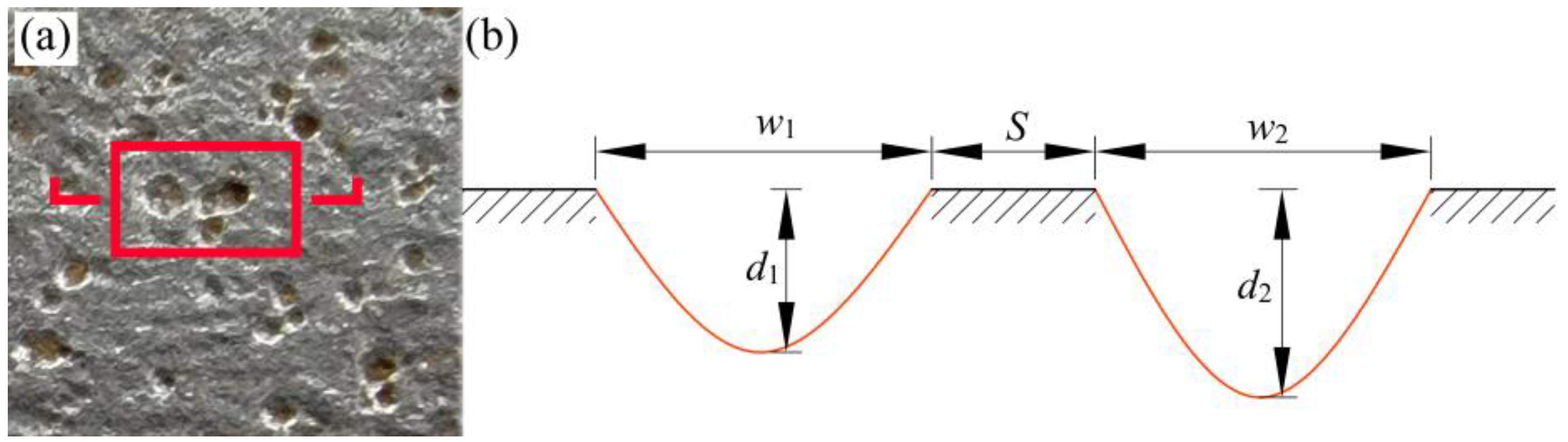
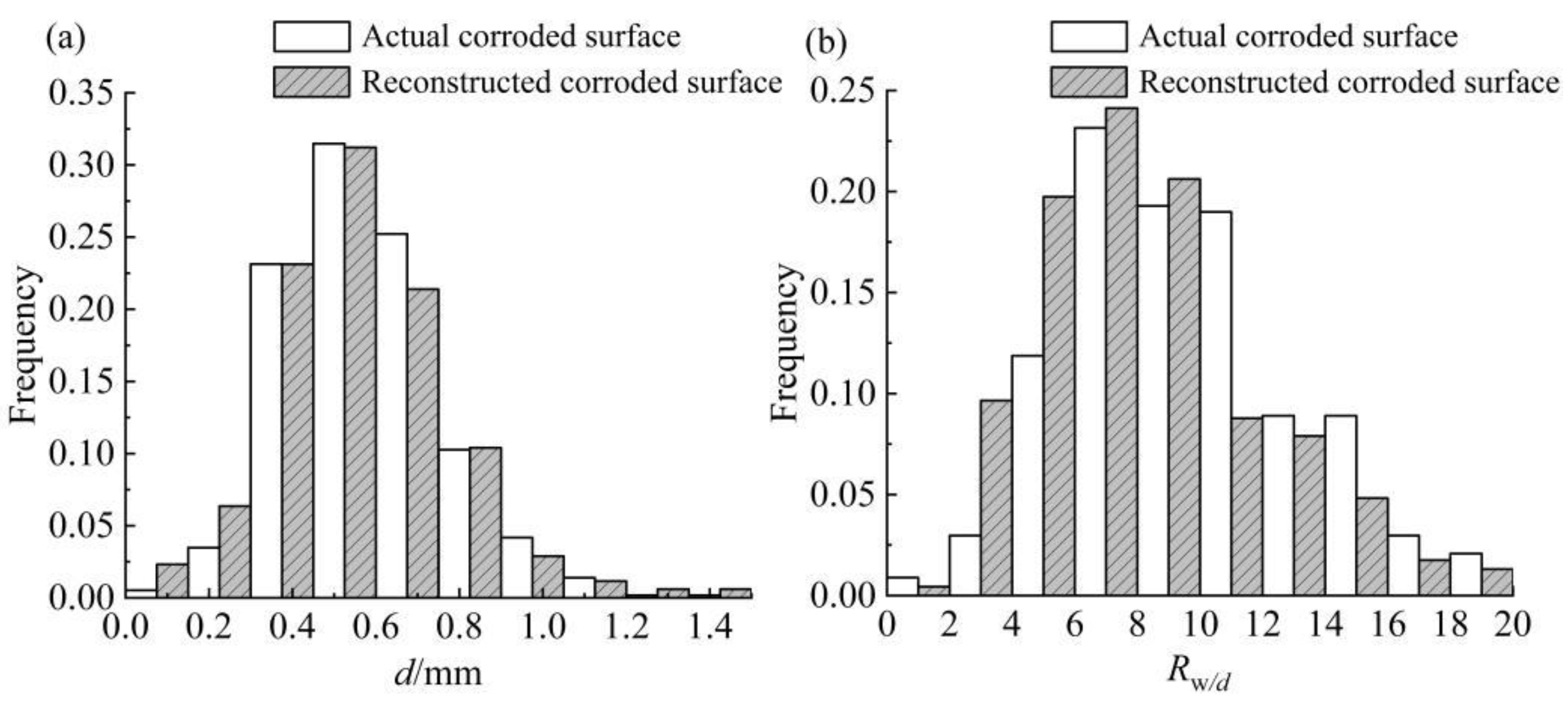
As is well known, with corrosion time extending, corrosion pit on a corroded steel surface evolves continuously, and its pitting parameters, including pit depth (
d), pit width (
w), and diameter–depth ratio (
Rw/d), change accordingly. From a statistical point of view, there is a specific probability distribution law for pitting parameters [
29,
30,
31,
32]. Thus, the probability distribution law of pitting parameters can be used to describe corrosion pits level on steel structures, which can also be introduced to the stochastic FEA model for improving the accuracy of simulated corroded surfaces.
To summarize, the stochastic FEA method is widely employed in studying corroded steel structures. However, due to the oversimplification of the corroded surface, particularly the lack of considering the characteristics of corrosion pits, the surface morphology of the FEA model differs greatly from that of the actual corroded steel structures, making it difficult to ensure the accuracy of the calculation results.
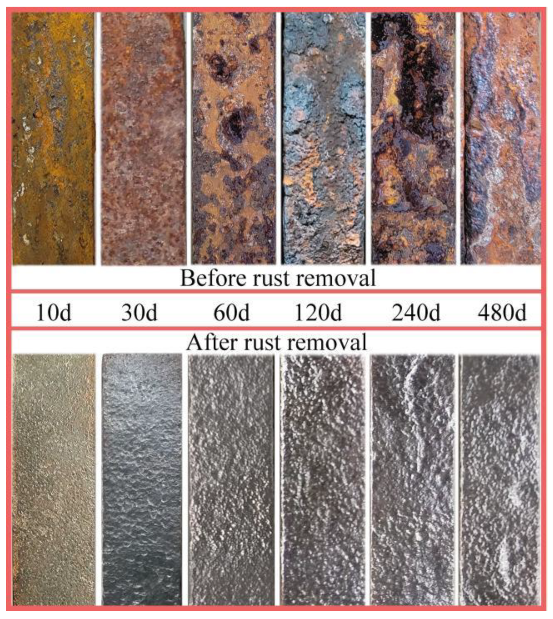
This work, therefore, set out to provide a modeling method that can simulate the corroded steel surface with higher accuracy and be used in FEA for studying the mechanical behavior of corroded steel structures. Based on this, firstly, the accelerated corrosion test was conducted to prepare six groups of steel specimens. Then, the distribution law of pitting parameters of all specimens was obtained by statistical analysis. Based on the statistical results, the random pitting model was proposed to simulate the corroded surface of steel structures. In addition, the rough surface meshing method was also developed for the FEA model of corroded steel structures to improve its element shape and enhance the calculation accuracy. Finally, based on the bending test of a corroded beam, the modeling method proposed in this study was applied to establish the FEA model of the steel beam with random pitting damage. Moreover, the calculation accuracy of the FEA model was confirmed by comparing it to the test results, which indicates that the modeling method provided in this study can be used for further mechanical behavior studies of corroded steel structures.
4. Numerical Model Verification of Corroded Steel Beams
According to Ref. [
37], the corroded surface morphology would tend to be stable when the measuring region of the corroded steel surface is greater than 20 × 20 mm
2. Therefore, the overall surface characteristics of corroded steel structures can be reflected by morphological characteristics of its part surface zone. This also further proved that the distribution law of the pitting parameters obtained by the measurement region can be used for modeling larger corroded steel members.
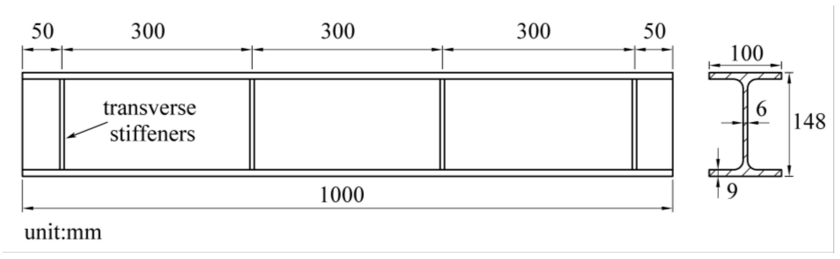
In this work, the bending test of corroded steel beams in Ref. [
8] was employed to verify the calculation accuracy of the FEA model established by applying the method proposed. The corroded steel beams used in the test were also obtained by an accelerated corrosion test, and their dimensions and corrosion degrees are shown in
Figure 12 and
Table 4, respectively.
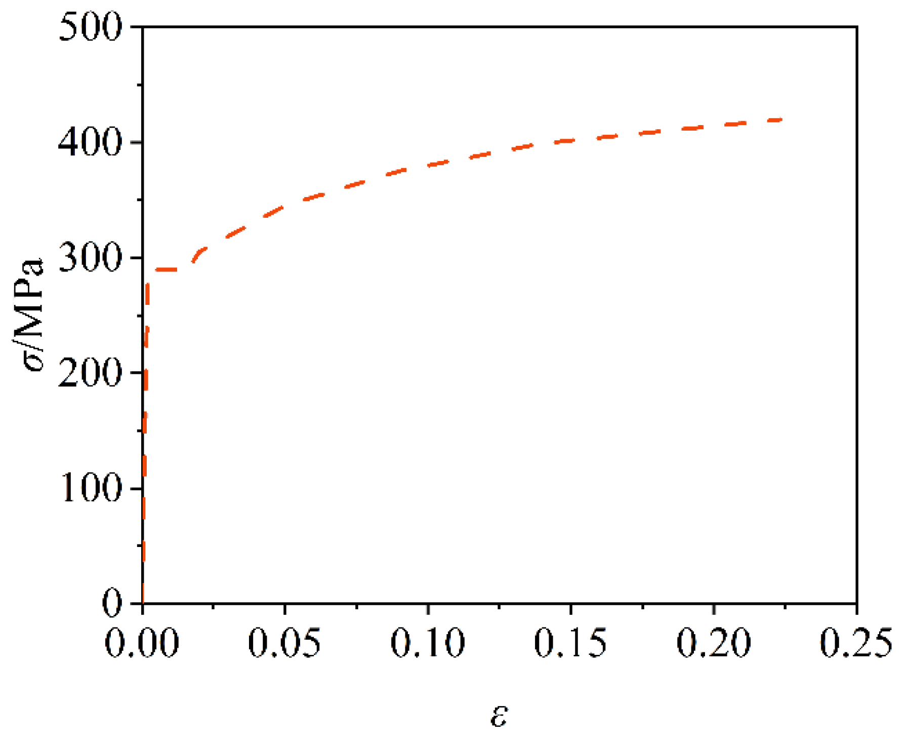
As is well known, steel is a typical plastic material; the linear constitutive model used in FEA will inevitably change the deformation state of steel beams and reduce the calculation accuracy. So, a multi-linear kinematic hardening model was utilized in this work to be the constitutive model of corroded beams, as shown in
Figure 13. As can be seen, this constitutive model comprised the entire elastic, yield, and strengthening phases, which were commensurate with the steel properties. Based on the test results in Ref. [
8], the related parameters of the constitutive model in FEA were illustrated in
Table 5.
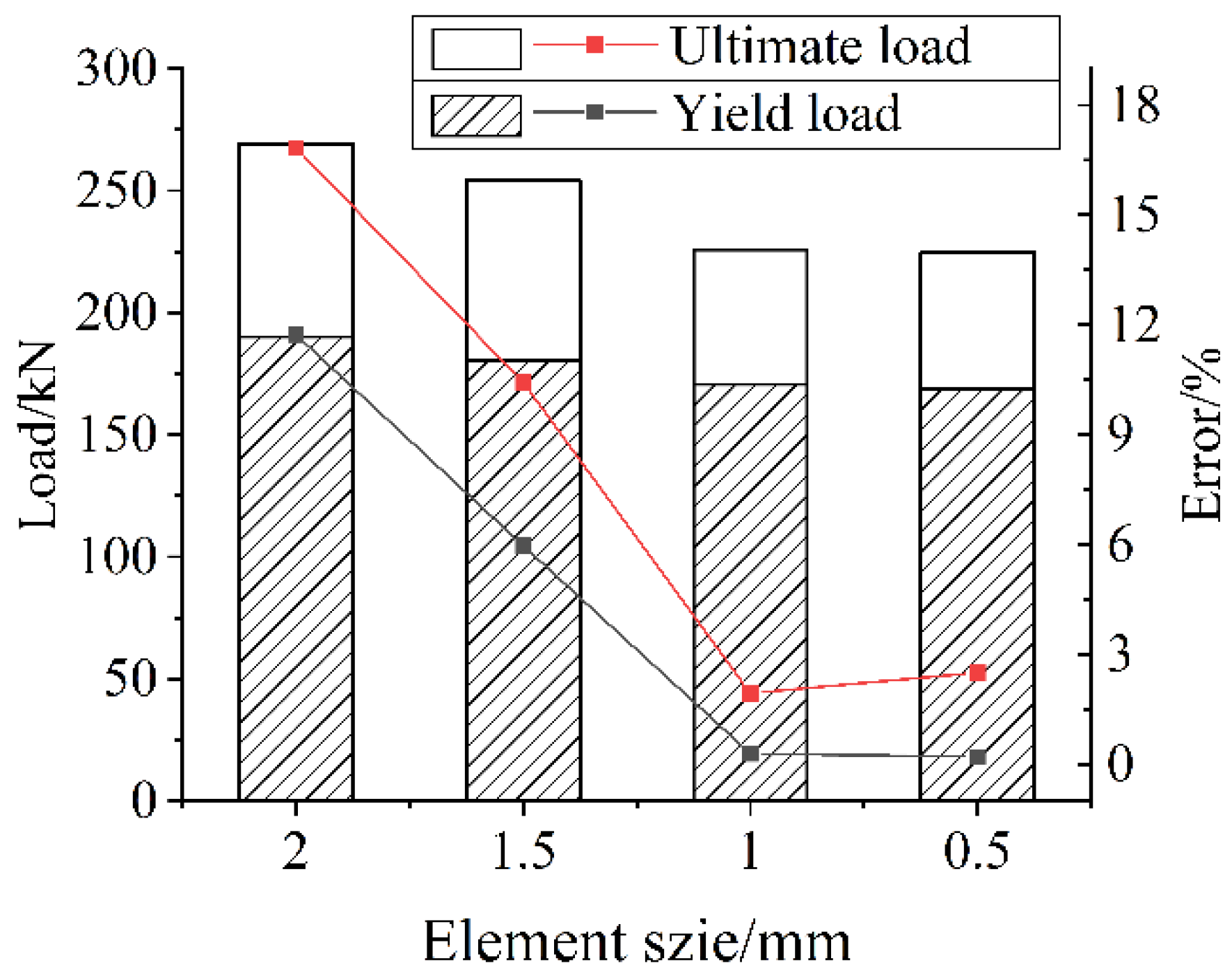
Three-dimensional solid elements, type C3D8R (8-node linear brick and reduced integration with hourglass control) were employed to model the corroded steel beam. This type of element demonstrates excellent ability for stress/displacement analyses. However, because the elements have only one integration point, it is possible for them to distort in such a way that the strains calculated at the integration point are all zero, which results in an uncontrolled distortion of the mesh. However, this can be solved by reasonably fining meshes, and can be minimized by distributing point loads and boundary conditions over a number of adjacent nodes [
38]. Thus, the size effect of the element was also studied to determine a reasonable element size. The result was illustrated in
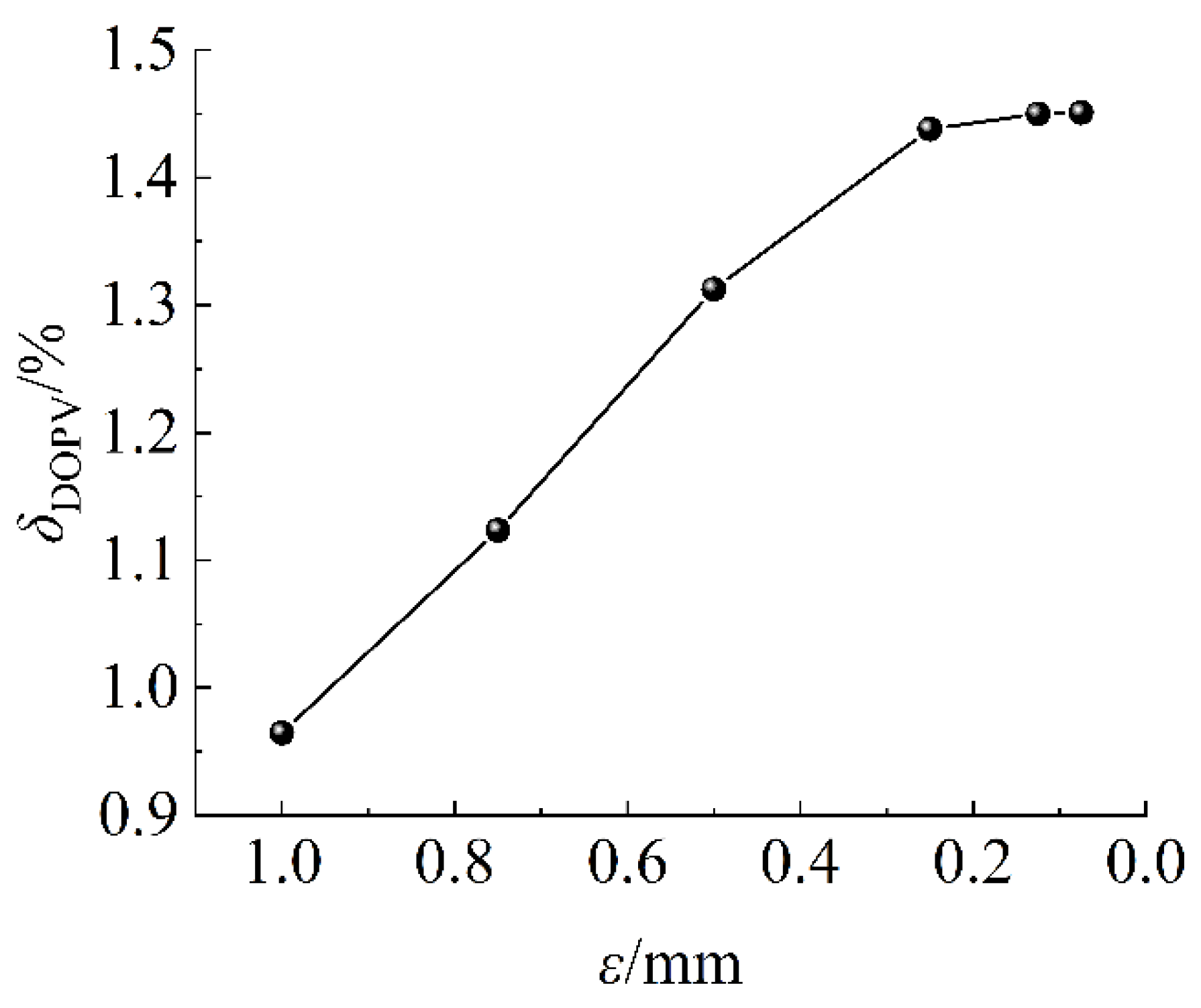
Figure 14. Note that, the size of the FEA model’s surface element determined the accuracy of the simulated corroded surface, which also affected the calculation accuracy. Therefore, the surface element should be refined, and the horizontal axis in
Figure 14 represents the surface element size.
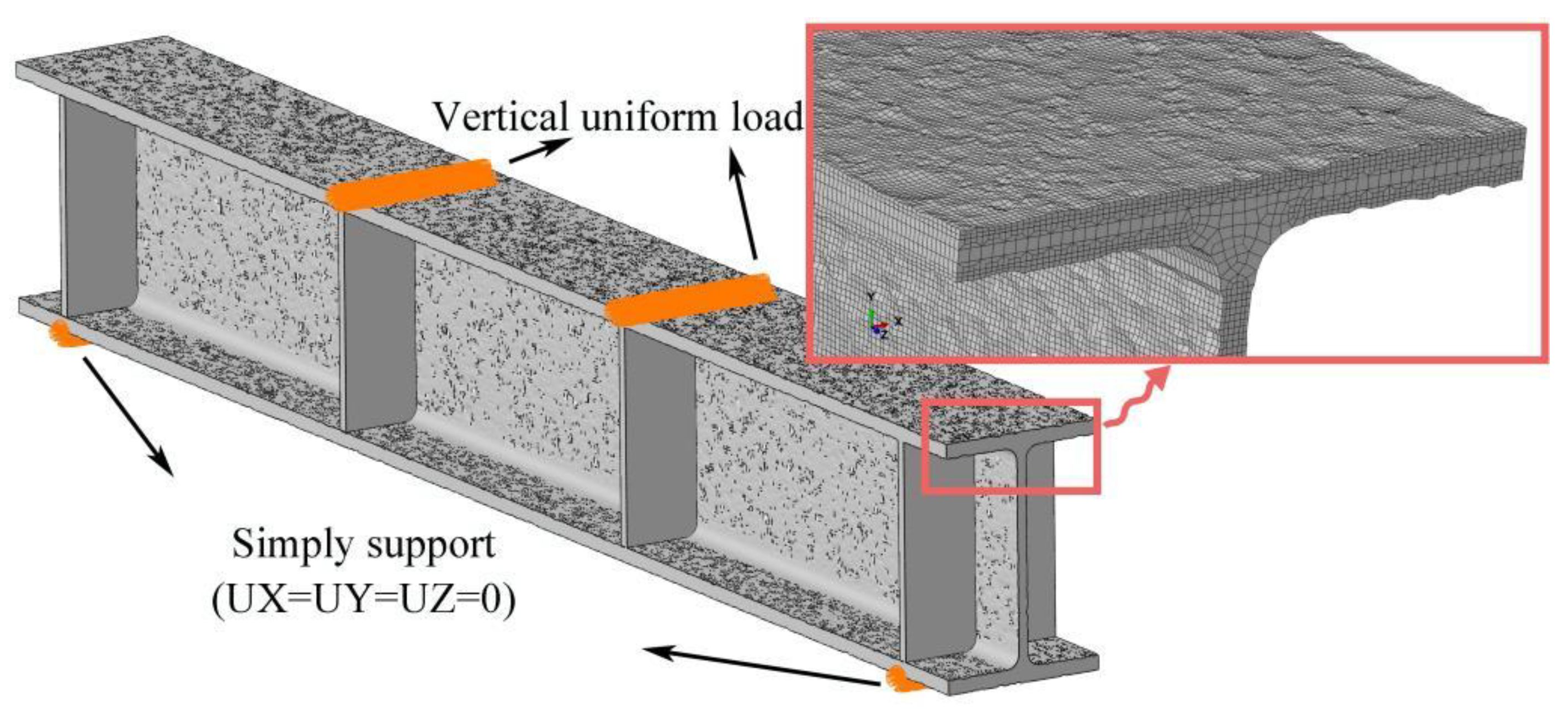
It can be seen from
Figure 14 that the calculation error decreased with the reducing of the element size. Apparently, while the element size was equal to 1 mm, the ultimate load and yield load calculation error converged. So, to reduce the calculation cost and improve its accuracy, the surface element size was refined to 1 mm, and the middle part with 2 mm element size. The boundary conditions of the model were consistent with the experimental conditions in the test, and the loads and boundary conditions were distributed to nodes at corresponding locations. The FEA model of the corroded beam is illustrated in
Figure 15.
To simplify the calculation, the following assumptions were made in the modeling process:
(1) The corroded steel beams were assumed as isotropy, so their η could be regarded as the δDOPV of it. Based on the value of δDOPV, the surface condition of the corroded beams could be appropriately connected with the specimens in this study during modeling: G1, G2—60 d; G3—120 d; G4—240 d; and G5, G6—480 d.
(2) It was assumed that the flanges and web had the same corrosion degrees, and the corrosion of the transverse stiffeners was not considered.
(3) The loading mode was displacement loading, which is easier to converge in FEA.
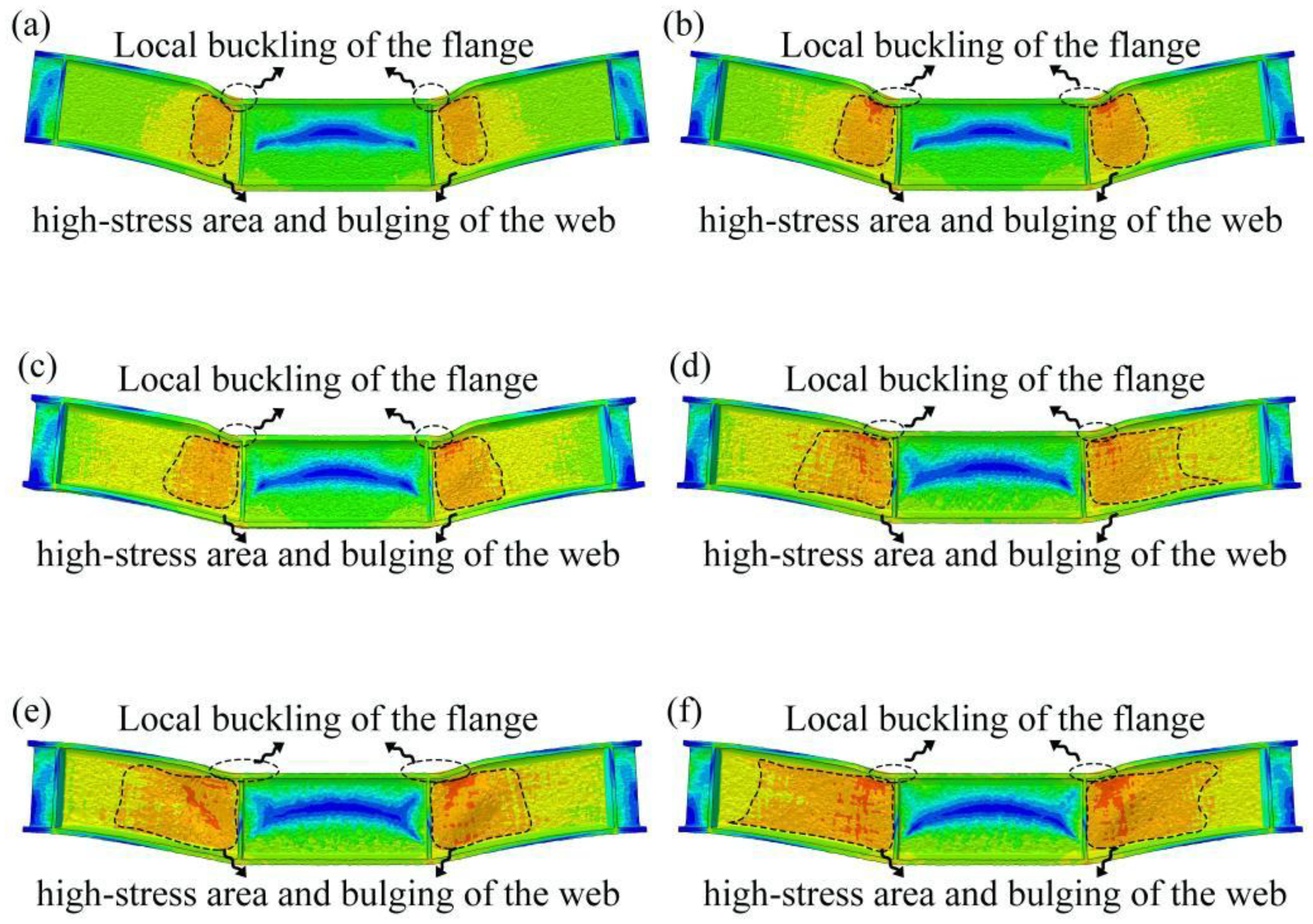
Figure 16 shows the FEA results of the corroded beam. As can be seen, the local buckling of the compressed flange and the bulging of the web occurred at the concentrated loading point, and the deformation becomes more obvious with the increase in corrosion degree. These deformation characteristics are consistent with those observed in the bending test [
8]. Additionally, it is evident from
Figure 16 that the stress distribution of corroded beams under various degrees of corrosion is different. Especially for the web, the high-stress area expanded with the corrosion degree. It is on account of that the evolution of corrosion pits causes the more complex corrosion morphology and larger scale of corrosion damage. Thus, it can be suggested that the characteristics of corrosion surfaces cannot be ignored in studying the mechanical properties of corroded steel structures.
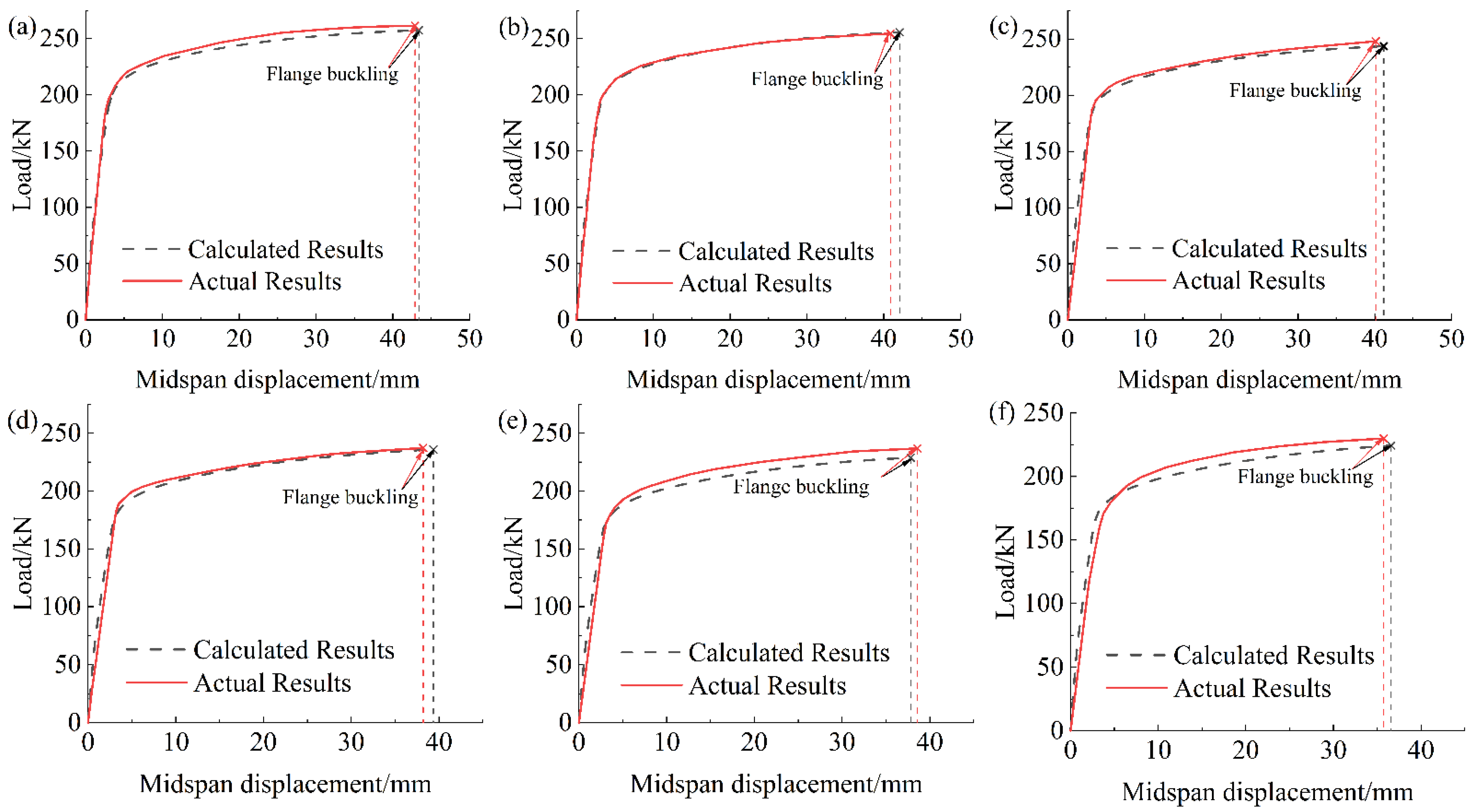
The comparison of the load–midspan deflection curve between the calculation results and the test results is shown in
Figure 17. Apparently, the load–midspan deflection curve of the FEA model agreed well with the test results. It is worth noting that, once the compressed flange buckled during the bending test, the load could not be continually increased [
8]. Thus, to better verify the analysis accuracy,
Fu of the FEA model was defined as the point at which buckling occurs during FEA.
Further, the bearing capacities of the corroded beam, including the yield load (
Fy), the ultimate load (
Fu), the displacement corresponding to the yield load (∆
y) and the displacement corresponding to the ultimate load (∆
u), of the FEA results and the test results are shown in
Table 6. It is apparent from this table that the maximum error of the bearing capacities between the FEA result and the test result is within 5%, which meets the engineering requirements. The present results confirm that the modeling method provided in this study could be well applied to investigate the mechanical properties of corroded steel structures.
5. Conclusions
The artificially accelerated corrosion test was carried out to obtain a batch of corroded steel specimens to investigate the distribution law of pitting parameters. Then, based on the statistical results of pitting parameters and the stochastic FEA method, the modeling and meshing methods for corroded steel structures were proposed. Finally, its calculation accuracy was verified by comparing it with the bending tests of the correlative corroded beams. The main conclusions are as follows:
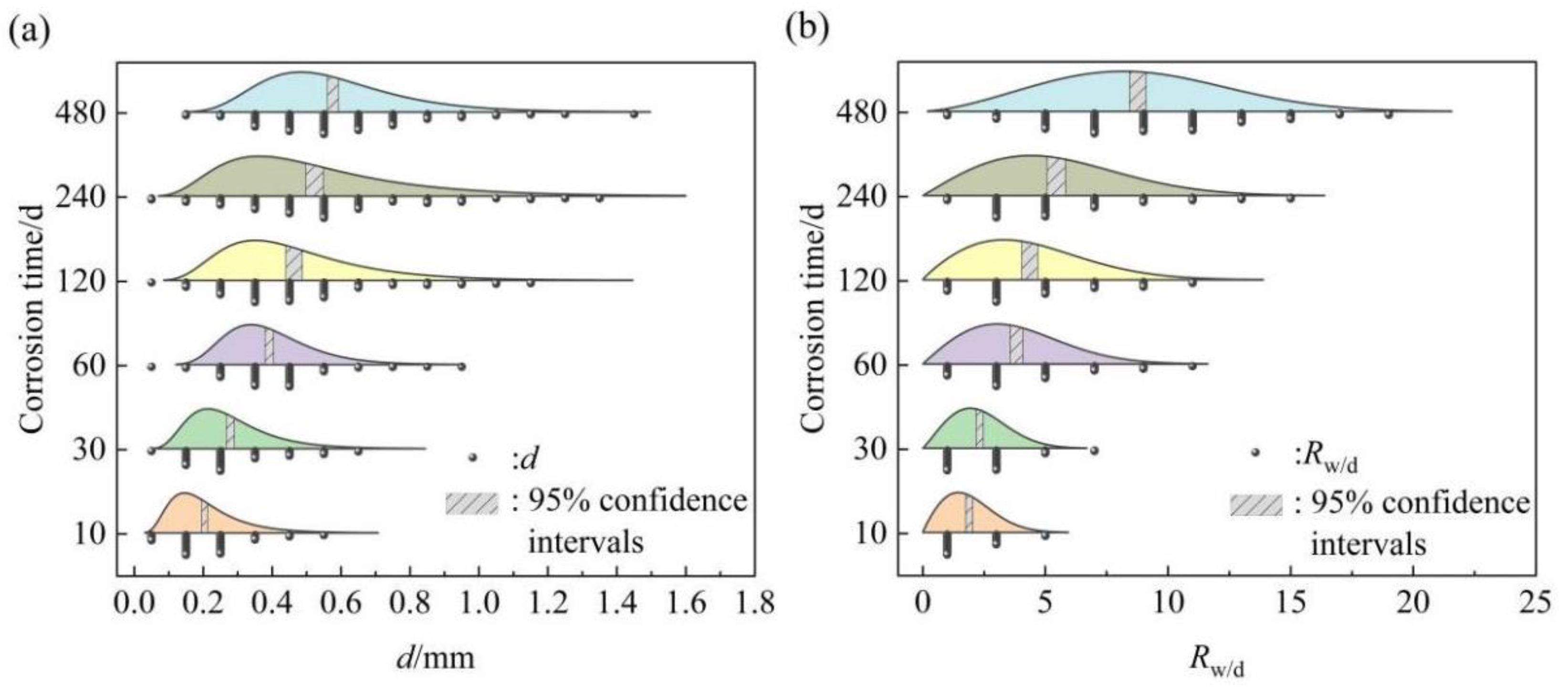
(1) The pit depth (d) and the diameter–depth ratio (Rw/d) of corrosion pits on corroded steel surfaces obeyed the log-normal distribution. Furthermore, the corroded morphological characteristics and the corrosion pitting evolution were mainly determined by the wide–shallow corrosion pits. It was also proven by the change law of the confidence interval of d and Rw/d.
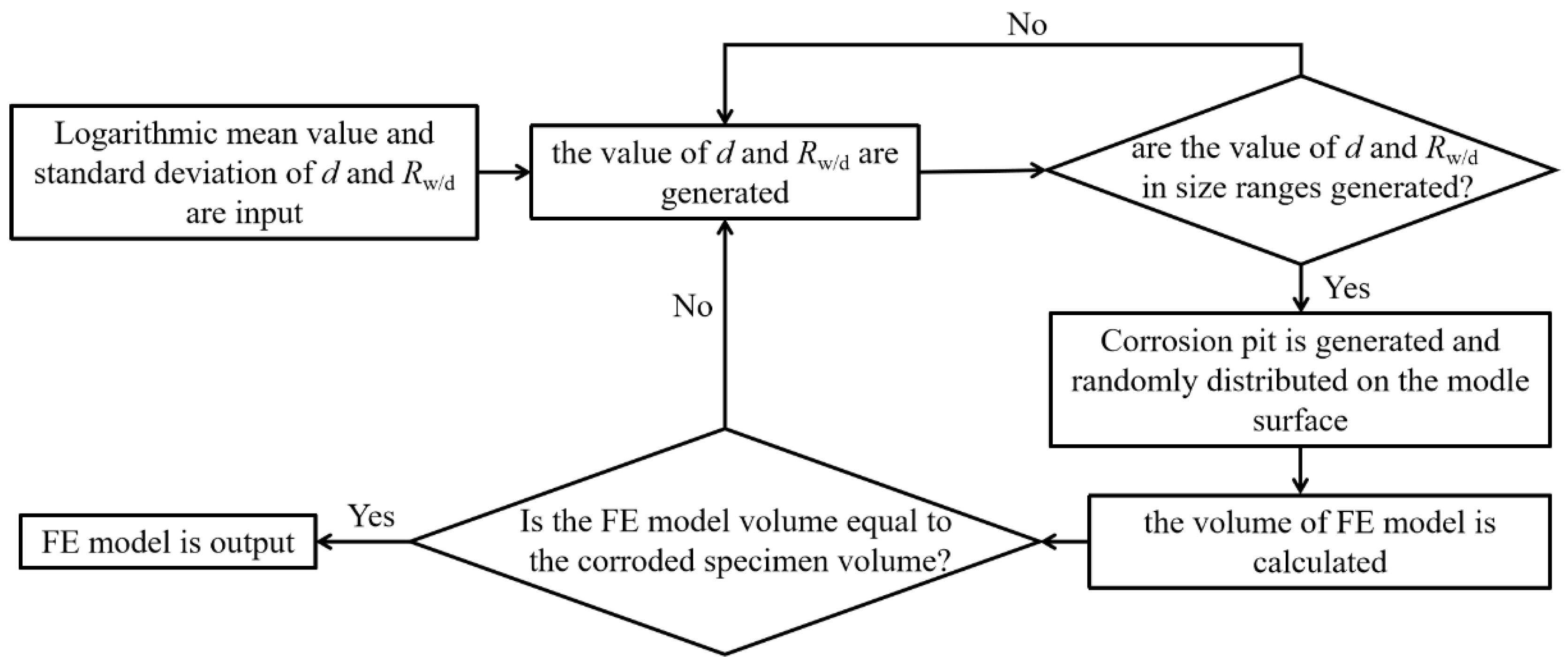
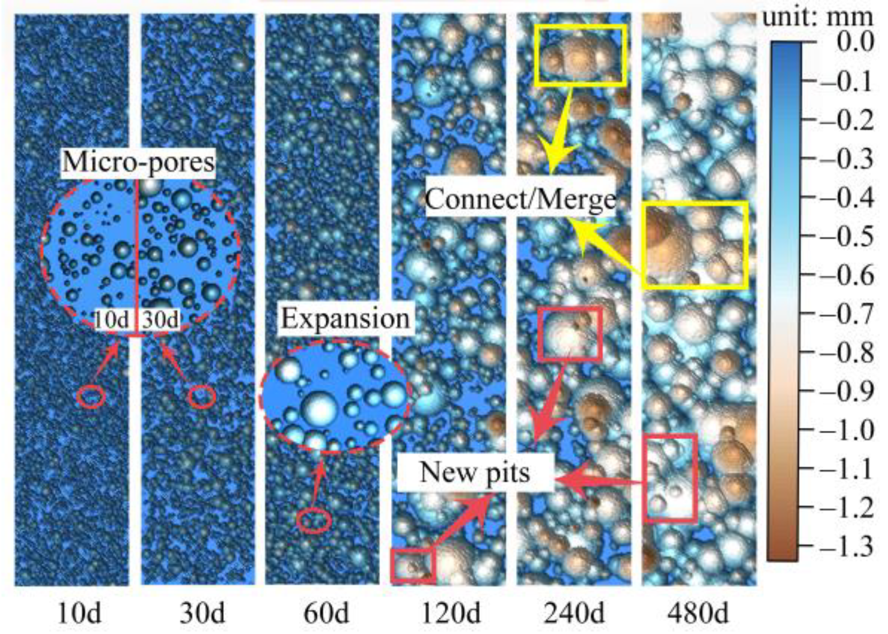
(2) The random pitting model (RPM), based on the statistical results of the pitting parameters and secondary development of ABAQUS, can be well used to simulate the FEA model of corroded steel structures. Moreover, the simulated surface reproduced a series of evolution characteristics of corrosion pit nucleation, growth, and connection with higher accuracy.
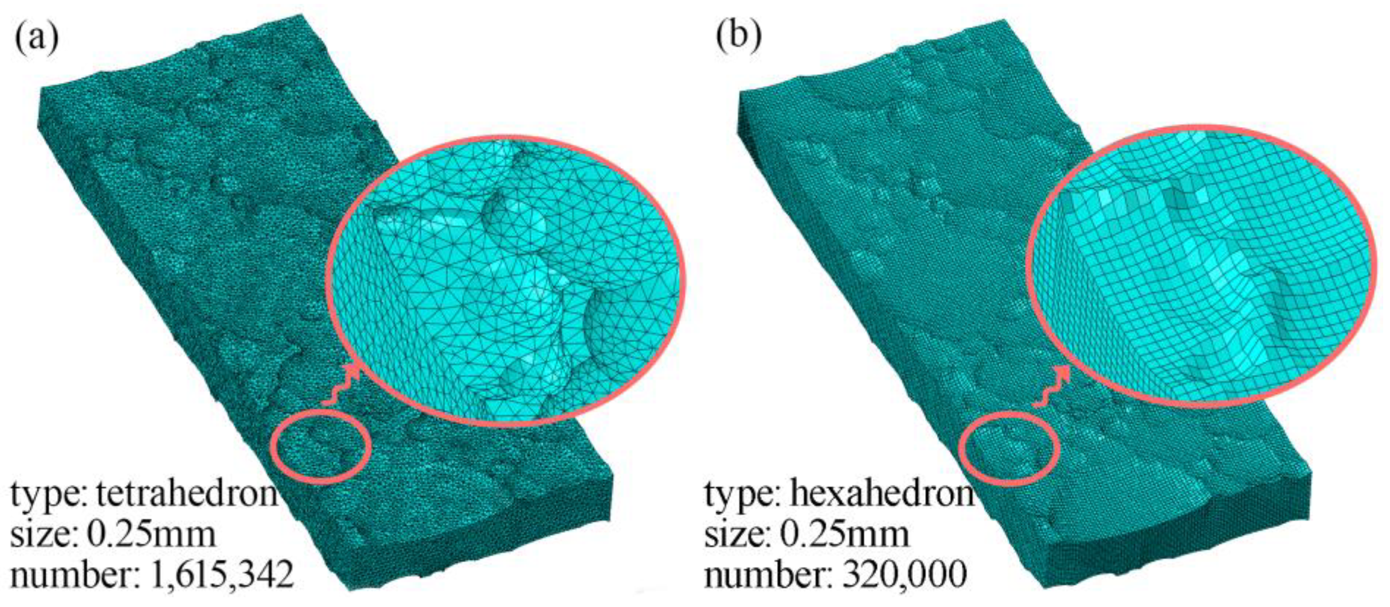
(3) The rough surface meshing method (RSMM) can be used to mesh the FEA model with an irregular surface into regular hexahedron elements. It cannot only reduce the number and distortion degree of elements, but also maintain the local information of the simulated surface. Additionally, the element number in the model can be easily adjusted by using the RSMM, and further to meet the accuracy requirements of the calculation results.
(4) By contrasting the bearing capacity of the corroded beam calculated by the FEA model with the test results, the comparison results show a less than 5% deviation between the FEA results and the test results for the bearing capacities of corroded steel beams. The provided modeling method with good reliability can be utilized further to study the mechanical properties of corroded steel structures in service.


