Article

Center of Stiffness, Principal Axes and Principal Start Point of Thin-Walled Open-Sections of Cores: A New Modified Calculation Technique Based on Vlasov Torsion Theory

by
Triantafyllos K. Makarios
and
Asimina Athanatopoulou
*
Institute of Structural Analysis and Dynamics of Structures, School of Civil Engineering, Aristotle University of Thessaloniki, GR54124 Thessaloniki, Greece
*
Author to whom correspondence should be addressed.
Buildings 2022, 12(11), 1804; https://doi.org/10.3390/buildings12111804
Submission received: 26 September 2022 / Revised: 13 October 2022 / Accepted: 21 October 2022 / Published: 27 October 2022
(This article belongs to the Section Building Structures)

Abstract

:
The present paper deals with the exact calculation of the Principal Elastic Reference System of R/C Cores, which have thin-walled open section. A new modified technique based on Vlasov torsion theory is developed that examines the warping phenomenon of cores. The exact position of the elastic center (or shear center) of a core and the orientation of the principal axes of elasticity, as well as the exact calculation of warping constant, are special parameters since, on the one hand it strongly affects the in plan stiffness distribution of the building members, and on the other hand it affects the values of the building eigen-frequencies and mode-shapes. These parameters are particularly critical in seismic design of asymmetric multistorey buildings. Based on Vlasov torsion theory of cores with thin-walled open sections, a repetitive mathematical procedure about the calculation of the location of the elastic center of core and the principal start point of the section is proposed. This new modified technique can be applied to cores of any shape. Afterwards, the exact diagram of sectorial coordinates of the section, as well as the warping constant, are calculated. All the above-mentioned parameters are very useful in the simulation of the cores in numerical models that are going to use in linear and nonlinear seismic analysis of the structures. Knowing all mentioned parameters, the numerical accuracy of the finite element method on cores can be checked. Finally, a numerical example, where the proposed new modified technique is applied on a fully asymmetric core, is presented.

Graphical Abstract

1. Introduction

One of the most common structural members that are used at asymmetric multi-storey buildings is the reinforced concrete (r/c) cores with thin-walled open section, which also are used very often in skyscrapers or other tall structures. The cores are usually used at the lift-location and staircase-position of the buildings. The cores, on the contrary with the columns or the plane shear-walls, have strongly spatial behavior because their section has three degrees of freedom (two translational displacements along the two horizontal axes, respectively, and a rotation about the core vertical axis).
The elastic center (or shear center) of the core section, do not coincide with the geometric center of the thin-walled sections, but in majority, it is located in another location that is far away from the geometric center. Furthermore, due to the existence of the core legs, large translational stiffnesses on the cores appear and large resistance in bend due to torsion of the core (Vlasov [1,2]) also appeared.
The existence of large values of the core stiffnesses significantly affect the torsional-translational behavior of the building, especially if the building is examined for seismic actions.
It is common, in the contemporary seismic codes, to attempt to simplify this issue of the core behavior, since they permit simple frame models for the simulation of the cores to be used, separated by the core legs in independent walls joined suitably at floor levels. However, such simulations insert disproportionately large discriminations in the whole building model, due to additional preconditions that are used in each technique of simulation. For example, when we insert auxiliary rigid (or semi-rigid) beams at floor levels into a flexural wall, then the frame model is transformed in a shear frame, the behavior of which is very different from that of the flexural wall. Furthermore, it is well-known in practice that the application of the finite element method at structural analysis has not achieved absolute application everywhere, but in many cases the simplified models are preferred (Xenidis et al. [3]).
The above-mentioned issues have concerned the international community in the past, but the problem of core simulation remain almost unresolved.
The use of an equivalent frame-model has been proposed for the planar shear walls from the decade of 1961 (Beck [4]; MacLeod [5]; Schwaighofer [6]). This model admits a simple simulation of the structural line-member that represents, with good accuracy, the behavior of simple or coupled planar shear walls to be analyzed via a standard software (of structural analysis) for planar frames (Schwaighofer and Microys [7]). The simplicity and effectivity of this model drives as a matter of course to extend its application in complex (or very complex) shear walls and in cores, doing 3D analysis of asymmetric multistorey buildings (Heidebrecht and Swift [8]; MacLeod [9]; MacLeod and Green [10]; MacLeod [11]; MacLeod and Hosny [12]; MacLeod [13]; Stafford-Smith and Abate [14]; Lew and Narov [15]; Stafford-Smith and Girgis [16]). However, after little time, significant lack on the numerical results by this model had been detected (Xenidis et al. [3]).
Considerable research with reference to the above-mentioned issue had shown that the application of this simulation in open, semi-open (that have link-beams at the floor levels, where the free-ends of core legs are jointing, Kheyroddin et al. [17]), and closed cores of buildings, when they subject at strong torsion, drives in inaccurate or wrong results of analysis (Girgis and Stafford-Smith [18]; Stafford-Smith and Girgis [19]; Avramidis [20]). The reliability of equivalent frame models for multi-cell cores, and especially for open multi-cell cores, is very poor, although such cores are very often encountered in practice (Xenidis et al. [3]). On the other hand, other researchers have examined special cases of pipes with closed thin-walled cross-sections, where the finite element method gave results with good agreement in symmetric cross-sections (Carpinteri et al., [21]; Zulli [22]; Lataski [23]).
In order to establish a satisfactory equivalent frame model, in the case where we are dealing with multi-cell cores, the issue of choosing between the various alternative solutions, as such examined by Xenidis et al. [3], become even more difficult and complicated than is in case of planar shear walls.
In order to simulate the asymmetric cores, there are many variations of equivalent frames, where the reliability of each one is unknown, and this can drive in wrong spatial frame models. This happens because the various techniques of the simulation of cores, which proposed in the past do not have the real properties of each core, such as (i) the location of the shear center (or elastic center) of the core, (ii) the orientation of principal horizontal axes, (iii) the position of the principal start point of the cross-section of the open core, (iv) the exact (that can be used for the exact calculation of the warping moment of inertia of the core) diagram of the sectorial coordinates of the cross-section of the open core, and (v) the warping constant (warping moment of inertia in units of length to the sixth power) of the thin-walled open core.
However, the calculation of all the above-mentioned properties is very difficult and for this reason a simple and easy applying procedure is needed in order to become known. This gap is the target of the present paper. In order to achieve this target, the Vlasov torsion theory is used, therefore all properties arise from closed mathematical procedure. Many researchers used the Vlasov torsion theory in order to solve various issues on the thin-walled open cross-section of cores (Alsheikh and Rees [24]; Choi et al. [25]; Chuong and Quy [26]; Lee [27]; Pavazza et al. [28]), because this theory constructs the warping deformation of the core.
Last but not least, having known all these properties/parameters of the examined open core (exact solution), all other approximative methods, such as the finite element method (FEM) and the various alternative variations of the equivalent frame model, can be evaluated. However, an issue regarding to the comparison between the theoretical solution and the FEM results is out of the target of the present paper, that has as its main target the developing of a new modified calculation technique of center of stiffness, principal axes, and principal start point of thin-walled open-sections of the cores. However, in analogous support material can be found the paper by Yu et al. [29].

2. Methodology

For the needs of the present article, the Vlasov torsion theory is used as a base for the structural members, which have thin-walled open sections, since this theory gives the possibility to obtain results by closed mathematical solutions. Afterwards, a modified form of this theory leads to the direct calculation of the location of the elastic center of the core cross-section. Therefore, following this, an easily-applied repetitive mathematic procedure has been developed, and this technique constitutes the main aim of the present article. The methodology that is used in the present paper is as follows:
  • Having known the geometric shape of the thin-walled cross-section of a core, the adoption of a temporary Cartesian three-orthogonal reference system, OXYZ, that will be used for the study of a thin-walled open section and calculation for the center of gravity, G, as well as for the orientation of the principal axes ξ and η of the cross-section of the core.
  • The calculation of the principal moment of inertia ( I ξ and I η ) of the thin-walled cross-section about the principal axes ξ and η passing through the gravity center G of the core cross-section.
  • The calculation of diagrams of coordinate-functions ξ ( s ) ,   η ( s ) of the thin-walled cross-section with regard to gravity reference system G ξ η z .
  • The calculation of the location of the shear center (that is also known as elastic center) K of the thin-walled open cross-section of the core, using a repetitive mathematical procedure.
  • The calculation of the position of the principal start point Μ ο ( x o ,   y o ) of the thin-walled cross-section of the core. It is worth noting that this principal start point of the open section defines the origin point where the calculation of the sectorial coordinates is based. Only referring to the principal start point, the numerical value of the warping moment of inertia I ω becomes minimum and this value is the exact value of I ω according to Vlasov torsion theory.
  • The calculation of the numerical value of the warping moment of inertia (or warping constant according other researchers, Bernuzzi et al. [30]) I ω of the thin-walled cross-section of the core.
  • The calculation of the warping stiffness of the core.

3. The Modification of the Vlasov Torsion Theory on Cores with Thin-Walled Open Section

3.1. General

According to Vlasov torsion theory [1,2], the following assumptions are set for the study of thin-walled open cross-section of a core:
  • The cross-sections of a thin-walled core remain undeformed into their level, namely each cross-section operates as one undeformed disk. This assumption is the known Bernoulli’s assumption (or assumption by Bernoulli-Navier) from the technical bending theory that applies on beams. According to this assumption, each cross-section of thin-walled is moved into its level as undeformed disk having three degrees of freedom (namely two translational along the two principal axes and a rotation about the longitudinal axis of the core.) For this purpose, we must insert into the thin-walled cross-section a point P, that possesses the above-mentioned three degrees of freedom (Figure 1). This point is called the “pole” of the thin-walled cross-section and the line that passes through this pole, and is parallel with the longitudinal principal axis (that is perpendicular on the disk of the thin-walled cross-section, namely along to Z-axis), is called the polar axis of the core.
  • The shear deformations of the above-mentioned structural member (namely the core) are considered null (assumption by Bernoulli).
  • The perpendicular lines that belong at the disk of the thin-walled open cross-section remain perpendicular and at the new position of the disk. This is the Kirchhoff assumption in the study of the thin plates.
Thus, according to the first assumption, each cross-section of a thin-walled open core moves into its level ( X o Y o ) as undeformed disk having three-degrees of freedom u x o ,   u y o ,   θ z , at the start point P, as shown in Figure 1. The diagrams of coordinate-functions S ( s ) ,   N ( s ) of the thin-walled open cross-section, with regard to reference system PSNZ, arise geometrically, or analytically using the rotation matrix R (Figure 1).
Figure 1. The kinematic conditions of a level of the thin-walled cross-section of a core.
Buildings 12 01804 g001
Indeed, we consider that the displacements u x o ,   u y o , θ z of the point P, are known. In order to calculate the displacements u s ,   u n of the random point M, at the local reference system Msnz, initially the two degrees of freedom u x o ,   u y o of the point P are rotated as vector, per angle α ^ (which is a function of the dimension s, namely α ^ ( s ) ) to get the displacements of the point P along S-axis and N-axis, respectively (Figure 1). Therefore, it is true that S ( s ) ,   N ( s ) are functions of the dimension s, since they happen at the alternated of the core-legs and at core-legs that having geometric curvature. Afterwards, according to kinematic conditions of the disk (of the cross-section), the displacements u s ,   u n of the random point M are given by the following Equations (where S m ( s ) ,   N m ( s ) are the coordinates of random point M, at reference system PSN):
u s = u x o · cos a + u y o · sin a N m ( s ) · θ z
u n = u x o · sin a + u y o · cos a + S m ( s ) · θ z
Therefore, from the Equations (1) and (2), the rotation matrix R is obtained:
R = [ cos a sin a sin a cos a ]  
The displacement u z ( s ) of the random point M in Z-axis is determined as function of the three degrees of freedom u x o ,   u y o ,   θ z of the point P as it is referred in the following Section 3.2.

3.2. The Warping Phenomenon That Gives Normal Stresses on the Thin-Walled Open Cross-Section of Core
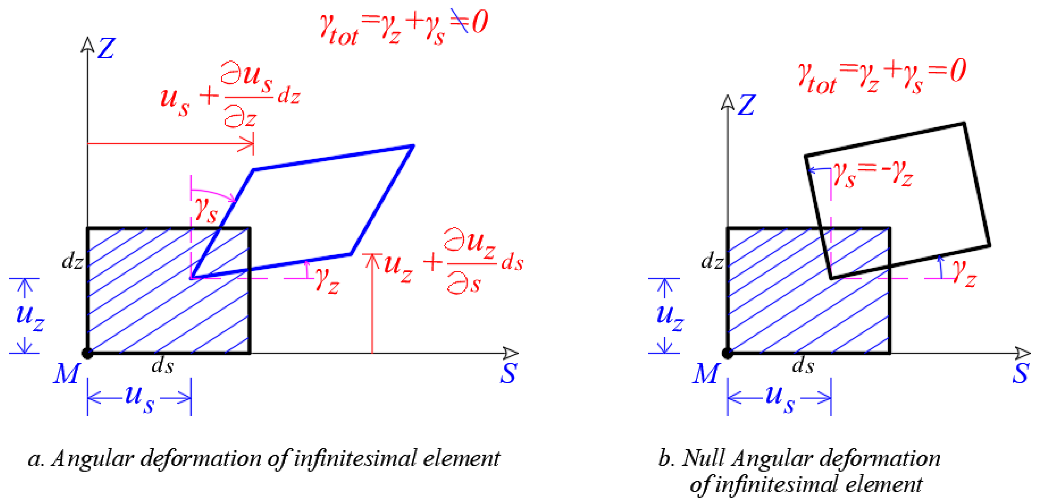
We consider an infinitesimal element d s · d z in view as it projected on vertical level (Figure 2) and since it can be deformed angular. Then, this element, appears total angular deformation γ t o t that is equal:
γ t o t = γ z + γ s = u z s + u s z
According to the second assumption, this infinitesimal element cannot appear angular deformation and thus the total angle of sideslip γ t o t is null (Figure 2b) and thus Equation (4) is written as:
u z s = u s z  
Figure 2. Angular deformation of an infinitesimal element on the vertical level SZ. (a) Deformation angle γs, γz, (b) null deformation angle.
Buildings 12 01804 g002
The integral of Equation (5) referring to space dimension s, gives:
u z ( s ) = 0 s u s z d s + u z ( 0 )    
Inserting Equation (1) into Equation (6) arises:
u z ( s ) = 0 s ( u x o · cos α + u y o · sin α N m · θ Z ) z d s + u z ( 0 )
u z ( s ) = u x o ( z ) z 0 s cos α ( s ) d s u y o ( z ) z 0 s sin α ( s ) d s + θ z ( z ) z 0 s N m ( s ) · d s + u z ( 0 )
u z ( s ) = [ u x o ( z ) ] 0 s cos α ( s ) d s [ u y o ( z ) ] 0 s sin α ( s ) d s + θ Z ( z ) 0 s N m ( s ) · d s + u z ( 0 )
However, from the geometry of Figure 3 we get:
d s · cos α ( s ) = d x ( s )
d s · sin α ( s ) = d y ( s )
N m ( s ) · d s = d w ( s )
Therefore, Equation (8) is written:
u z ( s ) = [ u x o ( z ) ] · x ( s ) [ u y o ( z ) ] · y ( s ) + θ Z ( z ) · ω ( s ) + u z ( 0 )
where
x ( s ) = 0 s cos α ( s ) ·   d s = 0 s d x ( s )
y ( s ) = 0 s sin α ( s ) ·   d s = 0 s d y ( s )
ω ( s ) = 0 s N m ( s ) · d s = 0 s d ω ( s )
[ u x o ( z ) ] = θ y ( z ) ,               [ u y o ( z ) ] = θ x ( z )
  • x ( s ) is the function of the Cartesian Coordinate x of the point M at the position s,
    y ( s ) is the function of the Cartesian Coordinate y of the point M at the position s,
  • ω ( s ) is the function of the Sectorial Area (or Sectorial Coordinate) of the point M. Function ω ( s ) , also, is known as «function of warping» or «measurement of warping» and as it will be proven bellow, its graphical image defines the distribution of the normal stresses on the cross-section of the thin-walled open core, in the case where core is loading with external bi-moment and simultaneously there is obstacle of the free torsion of the core.
  • θ x ( z ) and θ y ( z ) are the angles of the core cross-section about the horizontal axes, respectively.
As it is clear from the geometry of Figure 3, the parameter d ω ( s ) that first-appears into the third term of Equation (8) gives the double area that is formed from radius PM in the case where point M runs to the infinitesimal element on the mean line of the core-leg, since always the parameter N m ( s ) is the height of the triangle and simultaneously, the length ds is always the base of this triangle. This area, by conventional way, has positive sign when the PM is twisting according to reference angle θ Z (rule of clockwised-screw about Z-axis). Moreover, it is clear that the units of the sectorial coordinate ω ( s ) are units of area.
It is worth noting that the sectorial coordinate ω ( s ) , as it is obtained by Equation (12) is a function of the position of the pole P.
From Equations (1) and (2) we derive that the location of a core cross-section is absolutely defined into its level from the three degrees of freedom u x o ,   u y o ,   θ z . Thus, Equation (9) can be rewritten as:
u z ( s ) = θ y ( z ) · x ( s ) + θ x ( z ) · y ( s ) θ Z ( z ) · ω ( s ) + u z ( 0 )
In other words, from Equation (13) is derived that the Z-displacement ( u z ( s ) ) of the points of the core cross-section is depended of initial displacement u z ( 0 ) , the angles θ x ( z ) and θ y ( z ) as well as the first derivative θ Z ( z ) of the angle about Z that gives the change of the θ Z per unit length along Z-axis. This change is called twist. Namely, seven degrees of freedom exist instead of the six known degrees of freedom of a common joint of a spatial structure that is modeled with line-shaped structural member of a compact section.
Additionally, Equation (13) indicates that if a thin-walled open core is loading purely with torsion moment about Z-axis so as the twist of the core to be unity, namely:
θ x ( z ) = 0 , θ y ( z ) = 0 , u z ( 0 ) = 0 , θ Z ( z ) = 1
Then, axial displacements are developed, which are numerically equal with the distribution of the sectorial coordinates ω ( s ) on the cross-section of the core:
u z ( s ) = θ Z ( z ) · ω ( s ) = ω ( s )  
Additionally, it can be proven that using the material law strain-stresses from the elasticity theory, the normal stresses that act on the cross-section of the core are calculating by the following relationships (where all terms are clarified directly below):
σ z ( z , s ) = N ( z ) A x ( s ) · M y ( z ) I y + y ( s ) · M x ( z ) I x ω ( s ) · B K ( z ) I ω  
In the case where the gravity principal directions ξ and η of the core cross-section are rotated with regard to gravity reference system Gxyz, Equation (15) is written:
σ z ( z , s ) = N ( z ) A ξ ( s ) · M η ( z ) I η + η ( s ) · M ξ ( z ) I ξ ω ( s ) · B K ( z ) I ω    
where I ξ and I η are the principal moment of inertia of the thin-walled open cross-section about the principal axes ξ and η passing through the gravity center G of the cross-section (local reference system G ξ η z ), so as the product second moment of area as well as the product first moment of area to be null.
Equation (16) indicates that we work directly in local principal gravity reference system G ξ η z in order to calculate the normal stresses on the cross-section of a core. Then, in this case, the bending technical theory (Bernoulli) is true absolutely, using this theory separately on the two gravity principal axes (it concerns the second and the third term of Equation (16)). The values of the normal stresses are obtained from the superposition with the axial stresses from axial loading (first term of Equation (16)). The final values of the normal stresses are produced by superposition with the normal stresses from the bi-moment (fourth term of Equation (16)). Note that the positive sign of Equations (15) and (16) indicates the tension stress, while the negative sign indicates compression stress of the cross-section. Moreover, the sign of the bending moments is positive when their vectors have the same direction with the positive semi-axis of the reference system G ξ η z .
  • ξ ( s ) and η ( s ) are the functions of coordinates of the core cross-section referring to local reference system G ξ η z .
  • N ( z ) is the axial force of the core (along Z-axis), with cross-section area A and modulus of elasticity E of material:
    N ( z ) = Ε · A · u z ( z )
  • M y ( z ) is the bending moment at level z that acts on the cross-section of the core about y-axis, according to Bernoulli’s bending technical theory for the compact beams. I y is the moment of inertia of the cross-section about the y-axis that passes through the gravity center G of the thin-walled open cross-section, so as the product second moment of area as well as the product first moment of area to be null:
    M y ( z ) = Ε · I y · u x ( z )
  • M x ( z ) is the bending moment at level z that acts on the cross-section of the core about x-axis, according to Bernoulli’s bending technical theory for the compact beams. I x is the moment of inertia of the cross-section about the x-axis that passes through the gravity center G of the thin-walled open cross-section, so as the product second moment of area as well as the product first moment of area to be null:
    M x ( z ) = Ε · I x · u y ( z )
  • M η ( z ) and M ξ ( z ) are the bending moments at level z on the cross-section of the core about the principal directions ξ and η , respectively, that passe through the gravity center G of the open cross-section of the core.
  • B K ( z ) is the bi-moment or also known as “warping moment” at level z that acts on the open cross-section of the core (furthermore see Figure 4 and Figure 5). The parameter I ω is the “Warping or Sectorial Moment of Inertia” of the open cross-section of the core and has dimensions of length to the sixth power ( m 6 ). In order to calculate the Sectorial Moment of Inertia I ω the following two assumptions has to be always true:
    (i)
    The calculation of I ω must referred to principal pole P of the open cross-section, where this pole coincides always with the shear center (also called elastic center K) of the open cross-section;
    (ii)
    The principal start point Μ ο of the open cross-section has to be used always.
When these two above-mentioned assumptions are true, the sectorial moment of inertia I ω becomes numerically minimum, because the product sectorial moments I x , ω   ,     I y , ω (or I ξ , ω ,   I η , ω if the local principal directions ξ and η are different from the x and y-axes) are null, and the sectorial first order moment of inertia S ω is also null:
B K ( z ) = Ε · I ω · θ z ( z )
where
I x , ω = 0 A ω ( s )   y ( s )   d A , I y , ω = 0 A ω ( s )   x ( s )   d A , I ω = 0 A ω ( s ) 2   d A

3.3. Determination of the Elastic Center K of the Thin-Walled Open Cross-Section

In order to determine the position of the center of stiffness (or elastic center) of the thin-walled open cross-section, in the present paper the following repeating procedure is proposed:
First   attempt :   center   of   stiffness   ( or   elastic   center )   K ( 1 )
If we set the demand that, on the one hand, the product sectorial moment I η , ω to be null, and on the other hand, the product sectorial moment I ξ , ω to also be null, then we derive analytically that the coordinates δ ξ and δ η of the center of stiffness K ( 1 ) referring to pole P, are given from the following relationships (the exponent (1) gives the number of the repeats):
δ ξ ( 1 ) = I ξ , ω I ξ = 1 I ξ · C η ( s ) · ω ( s ) · e ( s )   d s
δ η ( 1 ) = I η , ω I η = 1 I η · C ξ ( s ) · ω ( s ) · e ( s )   d s  
where ω ( s ) is the diagram of sectorial areas of the cross-section referring to the temporary start point M, e ( s ) is the width of the core-leg as function to dimension s (when the width is variable), while ξ ( s ) and η ( s ) are known functions of coordinates referring to principal centro-gravity reference system G ξ η z . As the temporary start point M of the cross-section can be considered a random point of the cross-section, that has to be different from the elastic center K of the thin-walled open cross-section. Moreover, the point M has to remain constant in total duration of the repeating methodology. It is worth noting that the exact position of the principal start point M o of the thin-walled open cross-section is determined at the end of the proposed procedure (the calculations for determining the position of the stiffness center have been already completed). Therefore, note that the values of the two product sectorial moments ( I ξ , ω , I η , ω ) has to be null when these are calculated referring to the real stiffness center K of the thin-walled open cross-section. This does not happen during the first attempt and for this reason the repeating of the calculations is required:
Second   attempt :   center   of   stiffness ( or   elastic   center )   K ( 2 )
In the second iteration, we consider as pole P the point K ( 1 ) , having the same temporary start point M of the cross-section and we repeat all calculations. Afterwards, the new corrected coordinates δ ξ ( 2 ) and δ η ( 2 ) referring to point K ( 1 ) arise from Equations (22) and (23) and therefore the corrected center of stiffness (or elastic center) is called K ( 2 ) . If the declination between the position of the center of stiffness on the cross-section into the last two iterations is not small and hence unaccepted, then we continue the repeating procedure until this declination becomes very small and hence accepted. It is common that in order to achieve the convergence using this repeating procedure, the minimum number of required iterations are two or three, at least. Using analytical investigation that evolved in the present article, it has proven that the proposed repeating procedure always converged at the same point that is the center of stiffness of the thin-walled open cross-section. The number of iterations depends on the following two parameters: (a) the choice of the temporary pole P that is used in the first attempt, and (b) the choice of the position of the temporary start point M of the cross-section. In order to achieve faster convergence of the repeating procedure, the temporary pole P (in the first attempt) should coincide with the geometric center G of the thin-walled open cross-section. There is only one case of the non-stability of calculations and it is the case where the temporary start point M of the cross-section coincides coincidently at the same point with the real center of stiffness (that is unknowing in this phase). In this last case, the choice of another point as temporary start point M of the cross-section is needed.

3.4. Calculation of the Principal Start Point M o of the Thin-Walled Open Cross-Section

After finding the center of stiffness (or elastic center), we calculate the location of the principal start Point M o of the thin-walled open cross-section. For this issue, the following two parameters have to be calculated:
  • the final diagram of the sectorial coordinates ω ( s ) ; and
  • the sectorial moment of inertia I ω of the thin-walled open cross-section.
Both these last parameters are going to be used for the calculation of the normal stresses on the cross-section due to torsion-warping phenomenon.
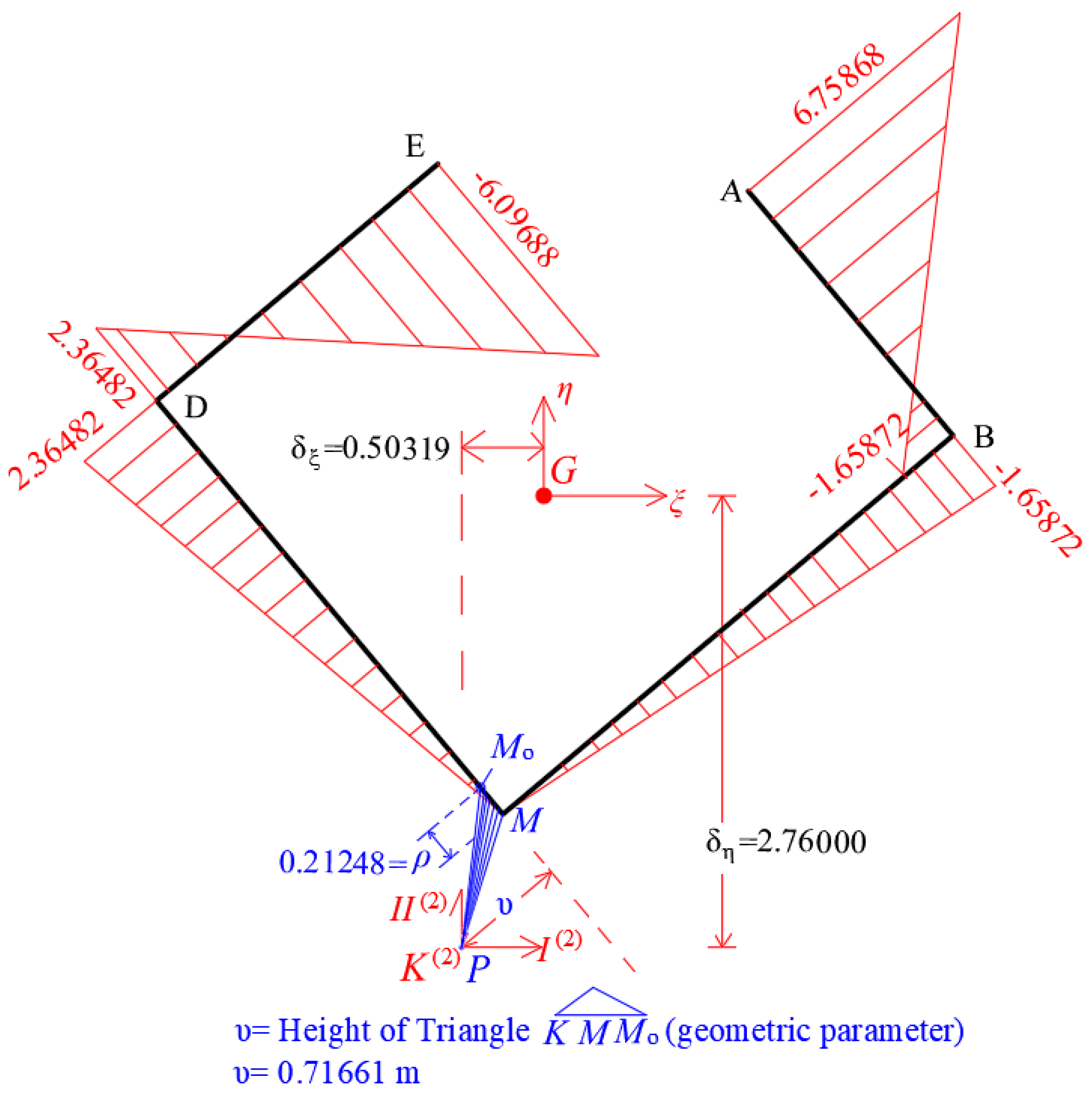
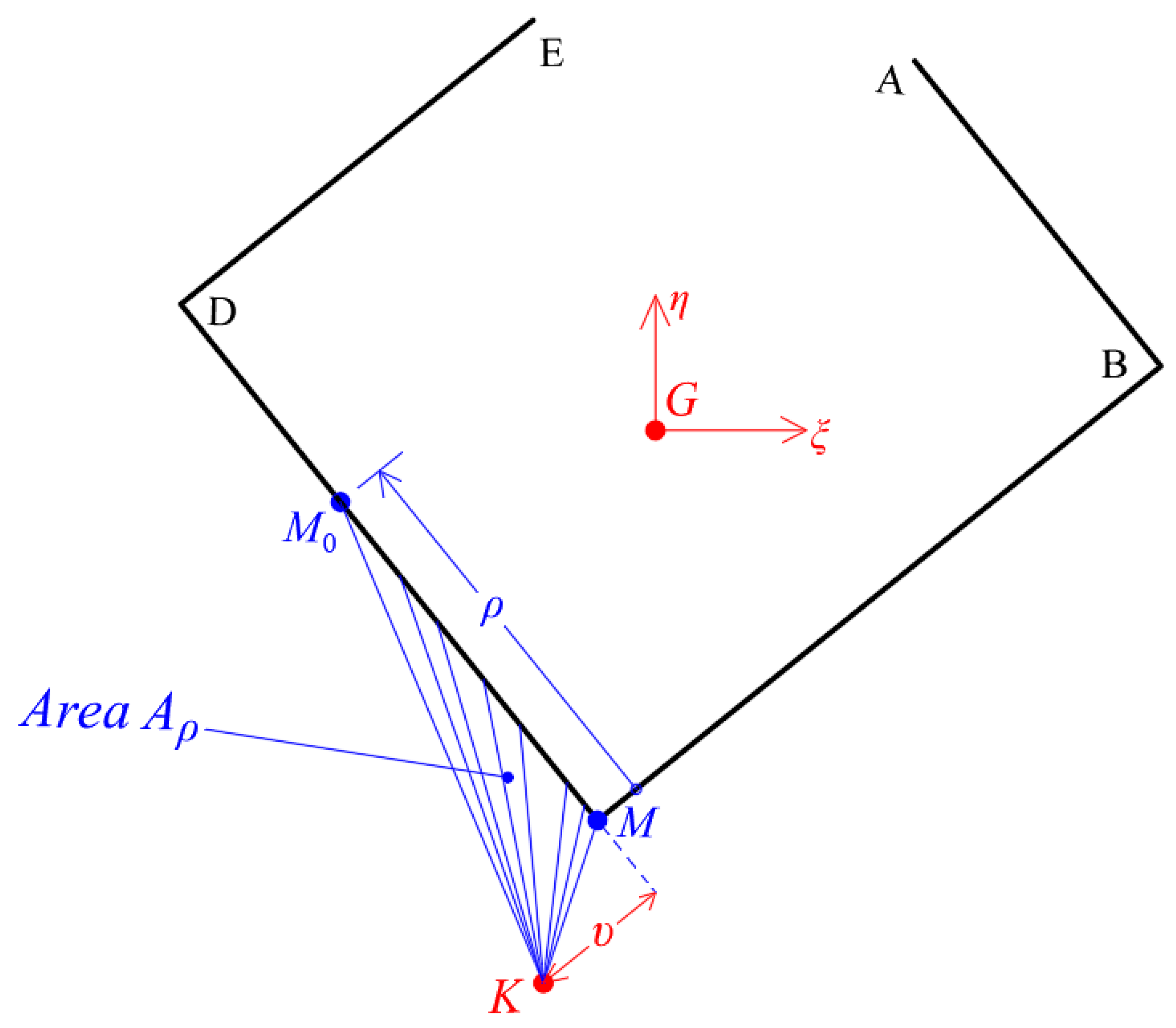
In order to calculate the location of the principal start point, initially, we are correcting the diagram of sectorial coordinates ω ( s ) ( Μ ) of the cross-section referring to final position of the center of stiffness K using the temporary start point M. Next, we are forming geometrically the ideal triangle Κ Μ Μ 0 , where the location of the principal start point Μ 0 is unknown and hence it has to be calculated (Figure 4). Its determination is achieved with the unknown distance ρ . The area A ρ of the triangle Κ Μ Μ 0 is given by:
A ρ = 1 2 · ρ · υ
where υ is the height of the triangle, which is known by geometrically way. Therefore, the distance ρ , from the temporary start point M, is given by:
Figure 4. Theoretical calculation of the principal start point M o of the thin-walled open cross-section.
Buildings 12 01804 g004
ρ = 2 A ρ υ = Ω ( ρ )   υ
The magnitude 2 A ρ (namely, the twice area of the triangle) gives the sectorial coordinate of the triangle Κ Μ Μ 0 (where the pole K has been used) and it is symbolized with Ω ( ρ ) , which is calculating from the following relationship:
Ω ( ρ ) = 1 A t o t · C e ( s ) · ω ( s ) ( Μ )   d s
where A t o t is the area of the thin-walled cross-section.
In the special case, where all legs of the core have the same width e, then Equation (26) is written:
Ω ( ρ ) = e A t o t · C ω ( s ) ( Μ )   d s  
It is worth noting that if the value of the Ω ( ρ ) has a negative sign, then the principal start point M o is calculating with negative rotation of the side KM for the triangle Κ Μ Μ 0 .
Knowing the principal start point M o , the final and corrected diagram of sectorial coordinates ω ( s ) of the cross-section (based on center of stiffness K) is calculated.

3.5. The Concept of the Bi-Moment

In the case where the external action on a structural member is a loading of torsional moments, the numerical calculation of the bi-moment’s diagram (or warping moment), which is symbolized as B K and its measure is in units of kN · m 2 , becomes with proportional way with the numerical calculation of the bending moment if we use loading of forces instead of torsional moments (with the same distribution along the structural member).
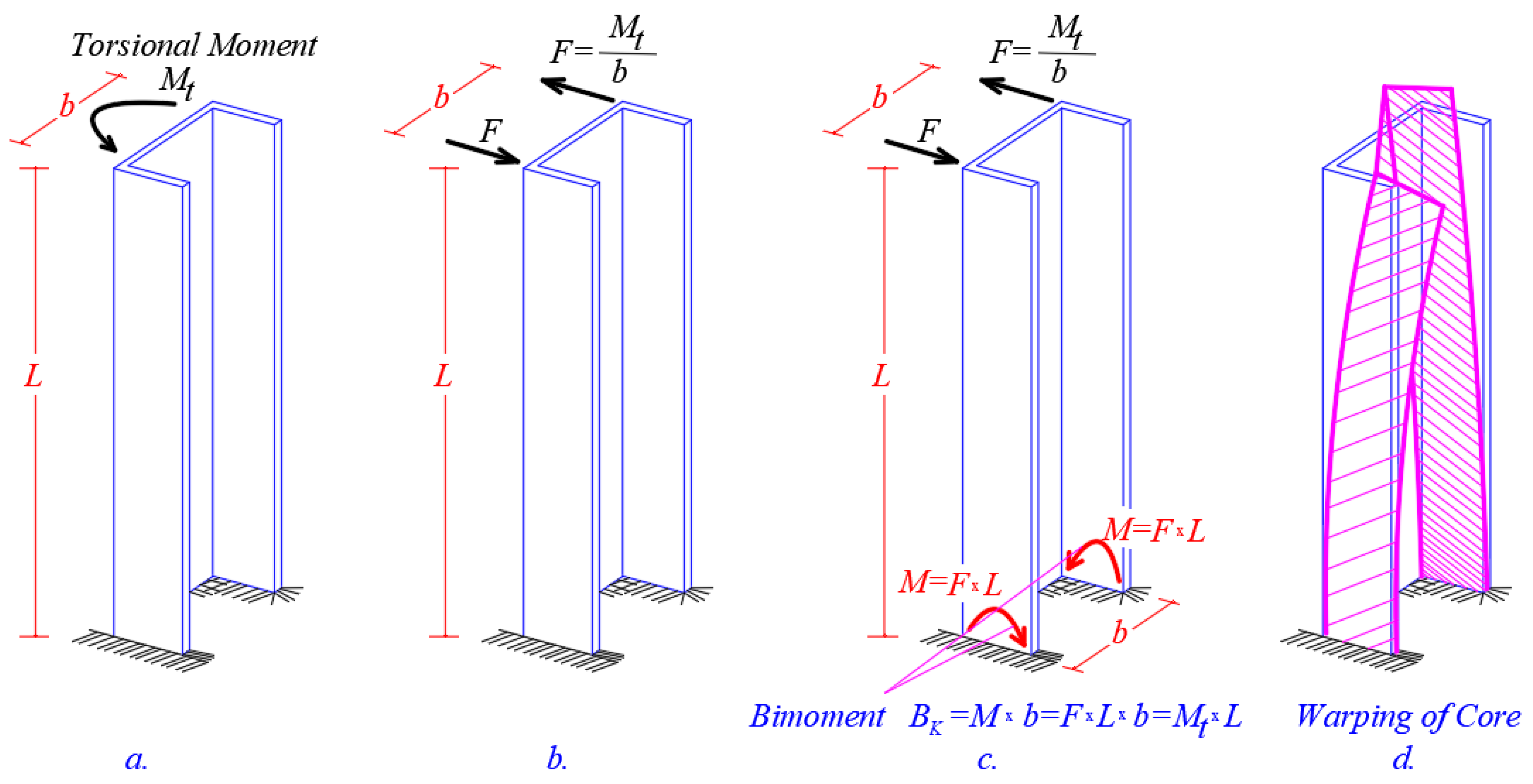
Figure 5. The natural concept (by qualitative point of view) of the bi-moment in a cantilever with thin-walled open cross-section and the torsion-warping phenomenon. (a) cantilever with a torsional moment at the top, (b) forces that produce the torsional moment, (c) bending moment and bimoment, (d) warping.
Buildings 12 01804 g005
In the special case where we have a core with thin-walled open cross-section, the bi-moment B K has natural concept (by qualitative point of view) (Figure 5), since the external torsion moment M t (Figure 5a) is analyzed equivalent in a pair of forces F × b (Figure 5b), where each force F gives at leg’s base the bending moment Μ = F × L , (Figure 5c). Each bending moment M gives normal stresses on the base cross-section. In other words, we have the phenomenon where an external torsion that acts on a structural member gives normal stresses on its cross-section, namely is something that does not describe and not foresaw the Saint-Venant torsion theory. The multiplying of the two bending moments M, by their lever-arm between them, is called bi-moment (or warping moment in the general case) Β Κ = Μ × b . It is worth noting that numerically, the warping moment diagram is equal with the respective ideal bending moment that is produced by the respective ideal external force loading (that is equal numerically with the external torsion moment M t , namely Β Κ = M t × L ). We can see in Figure 5d the torsion deformation of the core due to bi-moment Β Κ .

3.6. Principal Elasticity Axes I and II of the Thin-Walled Open Cross-Section
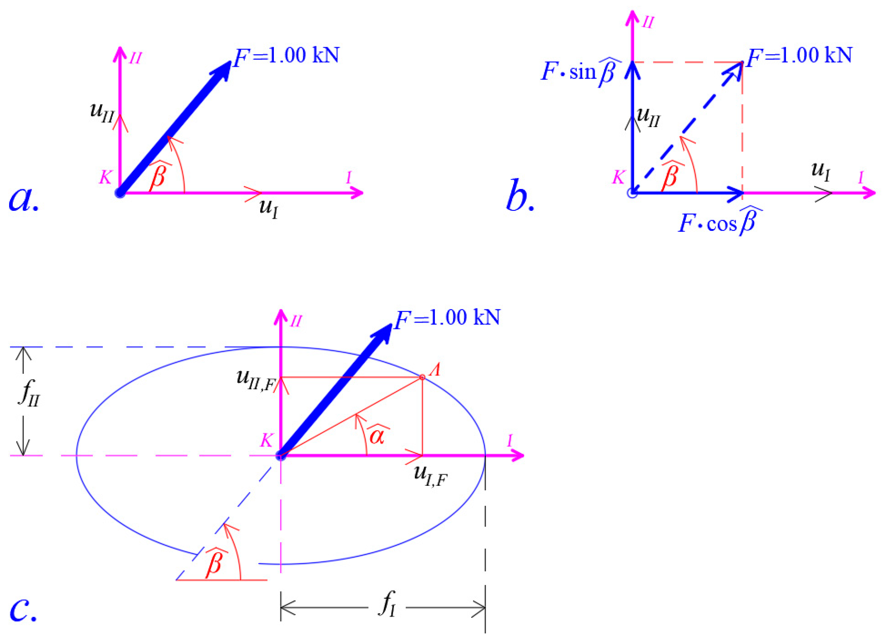
We consider a general core with thin-walled open cross-section, which has principal translational flexibility indexes f I ,   f I I (in m / kN ) along the two section axes I and II, respectively. Next, we consider that this core is loading with a unit static force F = 1.00 kN, that is applying on the center of stiffness (or elastic center) K forming the orientation angle β ^ with I-axis (Figure 6a). This static loading is analyzed in two components, along the I and II-axes. Therefore, we have the two equivalent forces, 1 · cos β along the I-axis and 1 · sin β along the II-axis (Figure 6b). In this case, the displacements of the center of stiffness K given by:
u I , F = f I · ( 1 · cos β )      
u I I , F = f I I · ( 1 · sin β )    
Hence the angle α ^ of the final displacement vector u = Κ Λ ¯ is given by (Figure 6c), where Κ Λ ¯ is displacement:
tan a = u I I , F u I , F = f I I · sin β f I · cos β = f I I f I · tan β  
Hence when f I f I I is true, then the translational displacement of the core due to static loading F does not become along loading direction. Next, Equations (28) and (29) are written:
u I , F 2 f I 2 = ( cos β ) 2        
u I I , F 2 f I I 2 = ( sin β ) 2
Adding per parts the Equations (31) and (32), an ellipse equation arises (Figure 6c):
u I , F 2 f I 2 + u I I , F 2 f I I 2 = 1.00  
We conclude that if the lateral static loading F is orientated along the I and II-axes, then the translation of the core becomes along the load direction. For this reason, the axes I and II are called principal axes of the cross-section and together with the vertical III-axis consist the principal elastic reference system K, I, II, III. On the contrary, if the lateral static loading F is orientated along different direction from the I and II-axes, then the translation of the core becomes along another direction than that defined by angle β (the displacement of the core does not coincide with the loading direction).
Figure 6. The principal I and II-Axes of elasticity. (a) direction of the force, (b) components of the force along I and II axes, (c) direction and components of the displacement.
Buildings 12 01804 g006

4. Numerical Example

4.1. Gravity Center G of the Thin-Walled Open Cross-Section and the Principal Centro-Gravity Directions ξ and η of the Cross-Section

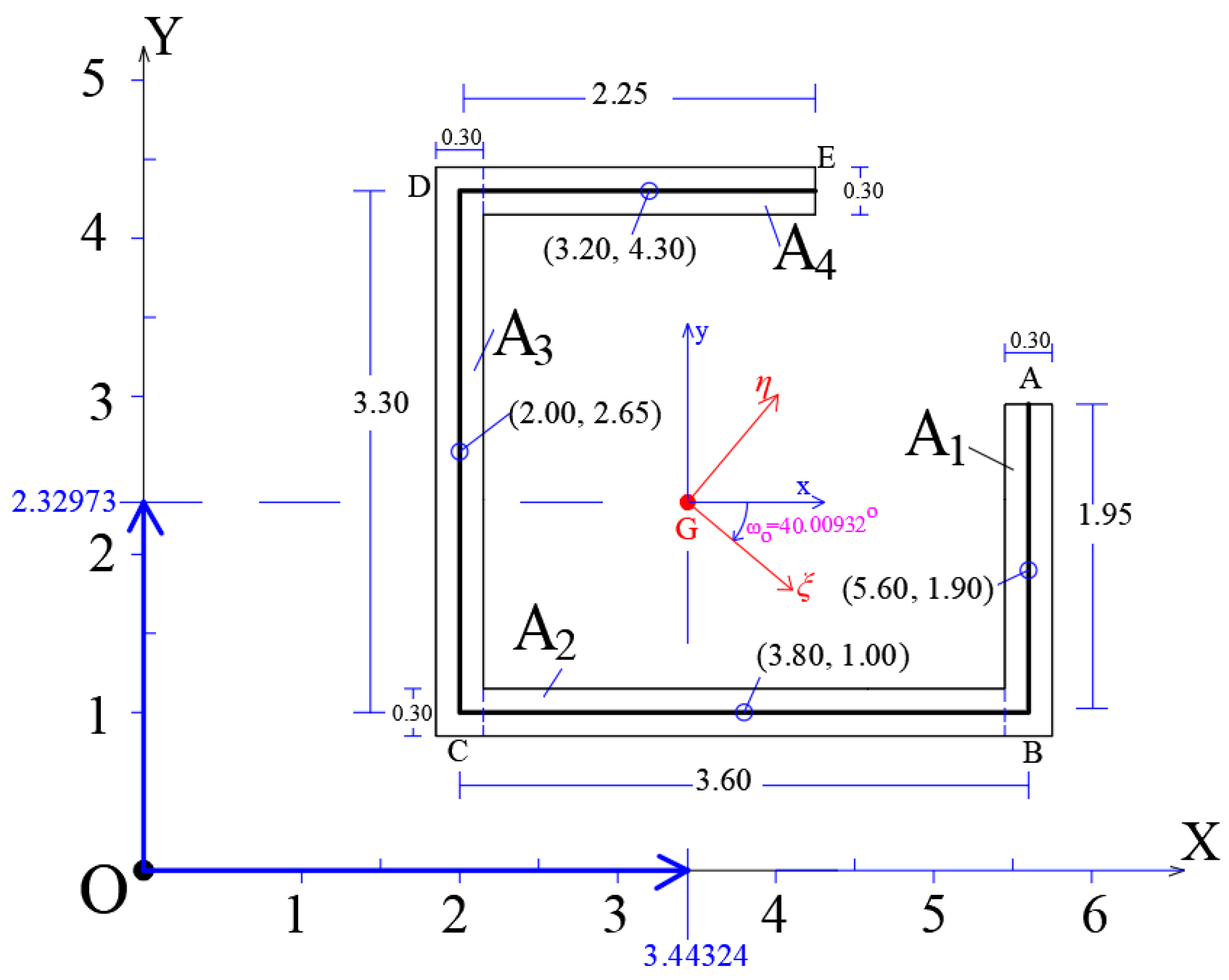
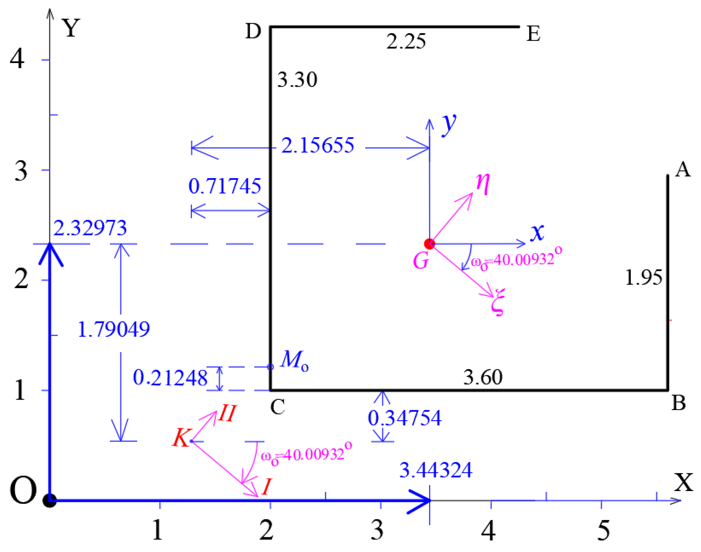
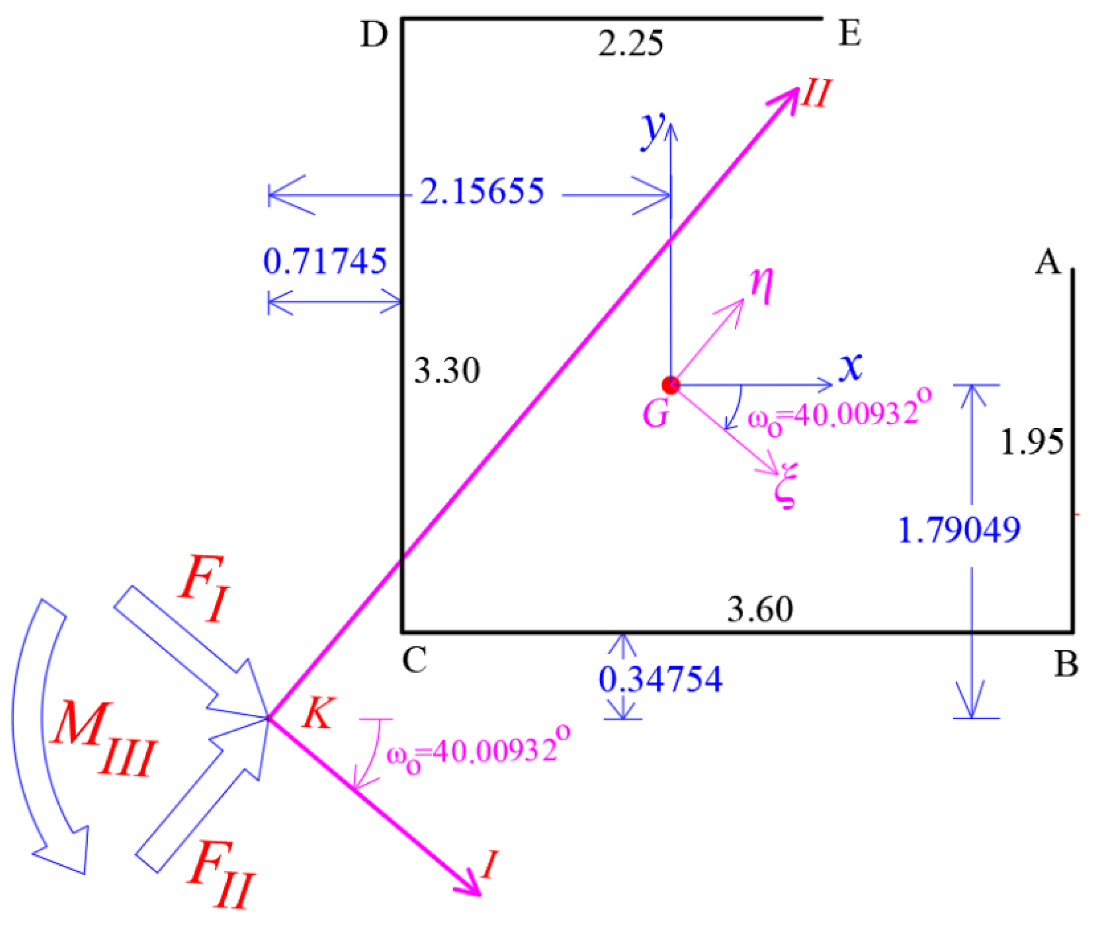
We consider the core of stairway with elements ABCDE that has thin-walled open cross-section (Figure 7), where all legs have the same width e = 0.30 m. We take an arbitrary, temporary Cartesian reference 3D-system OXYZ (where OZ-axis is the vertical axis, generally) and we are forming geometrically the mean line of the thin-walled open cross-section and we calculate the position of the gravity center G of the section, and its principal directions ξ and η . For this purpose, separate ideally the thin-walled section at four rectangle areas ( A 1 ,   A 2 ,   A 3 ,   A 4 ) , while all calculations are shown in the Table 1:
Hence the coordinates ( X G ,   Υ G ) of the gravity center G of the thin-walled open section referring to temporary reference system OXYZ, are given by:
X G =   X i · A i   A i = 11.466 3.33 = 3.44324   m
Y G =   Y i · A i   A i = 7.758 3.33 = 2.32973   m
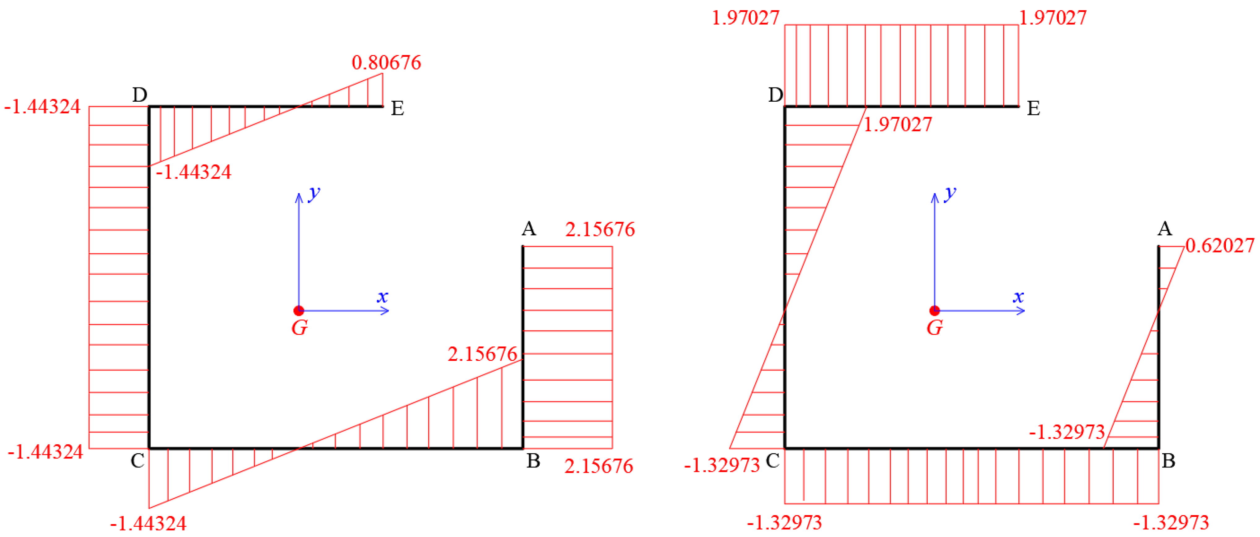
Afterwards, we consider a new temporary, Cartesian reference 3D-system at gravity center G, which is called Gxyz. At this local 3D-system, we can calculate geometrically the diagrams of the functions of coordinates x ( s ) ,   y ( s ) of the thin-walled open cross-section (Figure 8):
Next, Table 2 is filled. In the two first columns we are inserting the coordinates x, y of the gravity center of each core leg A i referring to Gxyz. At column I x i , the moment of inertia of each core leg (about its local x-axis, Figure 8) is inserted. In a similar way, at column I y i , the moment of inertia of each core leg (about its local y-axis) is inserted, too. In the next column I x x , the moment of inertia of each core leg with regard to gravity center G (about G,x-axis) is calculated using the Steiner term A i ( Υ i Υ G ) 2 , where Υ i and Υ G are the y-coordinates of the gravity center of the A i area and of the core, respectively. Similarly, at the next column I y y , the moment of inertia each core leg referring to gravity center G (about G,y-axis) is calculated using the Steiner term A i ( Χ i Χ G ) 2 . At the last column, the product moment of inertia ( I x y ) for each core leg is inserted using the Steiner term (XiXG) · (YiYG).
Hence, the moments of inertia for the total thin-walled cross-section are given by the following relationships:
I x x = d A y 2 d A = i I x i + A i · ( Y i Y G ) 2  
I y y = d A x 2 d A = i I y i + A i · ( X i X G ) 2  
I x y = d A x · y · d A
Alternately, for cores with very thin legs, the following relationships can be used, approximately:
I x x = d A y 2 ( s ) · e ( s )   d s
I y y = d A x 2 ( s ) · e ( s )   d s
I x y = d A x ( s ) · y ( s ) · e ( s )   d s
where e ( s ) is the width of each core leg.
It is worth noting that in the examined core, the functions x ( s ) ,   y ( s ) appear linear form along the core legs of the mean line of cross-section. Hence, in order to calculate the above-mentioned integral, suitable closed mathematical relationships can be applied (multiplying of two trapezium diagrams for each core leg). For example, if the length of a core leg is L and this core leg has constant width e ( x ) = e , we have two linear first order functions referring to x, that called f ( x ) and g ( x ) . In this special case, in order to avoid analytical calculations, the respective integral is given by the following relationship:
0 L f ( x ) · g ( x ) · e ( x )   d x = e · L 6 · [ a ( 2 c + d ) + b ( c + 2 d ) ]
where all parameters (can have positive or negative sign) are shown in Figure 9:
f ( x ) = a + x · ( b a ) L
g ( x ) = c + x · ( d c ) L
Figure 9. Parameters a ,   b ,   c ,   d ,   L .
Buildings 12 01804 g009
Table 2. Calculation of moments of inertia of the cross-section of the core.
Number ( X i X G ) ( Y i Y G ) I x i I y i I x x I y y I x y
A12.15676−0.429730.231530.004730.347872.93523−0.5839
A20.35676−1.329730.007430.898431.757921.02443−0.46965
A3−1.443240.320271.166400.008101.277182.25769−0.49921
A4−0.243241.970270.004730.231532.450360.26880−0.30193
Sum 5.833336.48615−1.85468
Furthermore, the orientation of the principal directions ( ξ and η ) of the thin-walled open cross-section is defined by the angle ω ο that is given by:
tan ( 2 ω ο ) = 2   I x y I y y I x x = 2 · ( 1.85468 ) 6.48615 5.83333 = 5.68209         ω ο = 0.698294   rad
or     ω ο = 40.00932   ο
see Figure 7.

4.2. Principal Moments of Inertia ( I ξ and I η ) of the Thin-Walled Section about the Principal Directions ξ and η of the Gravity Center G of the Cross-Section

The principal moments of inertia ( I ξ and I η ) of the thin-walled section about the principal directions ξ and η of the gravity center G are calculating by:
I ξ = I x x + I y y 2 + ( I x x I y y ) 2 · cos ( 2 ω ο ) I x y · sin ( 2 ω ο ) = 4.27656   m 4
I η = I x x + I y y 2 ( I x x I y y ) 2 · cos ( 2 ω ο ) + I x y · sin ( 2 ω ο ) = 8.04292   m 4

4.3. Calculation of Diagrams of Functions of Coordinates ξ ( s ) , η ( s ) of the Thin-Walled Cross-Section at Cartesian Reference 3D-System G ξ η z

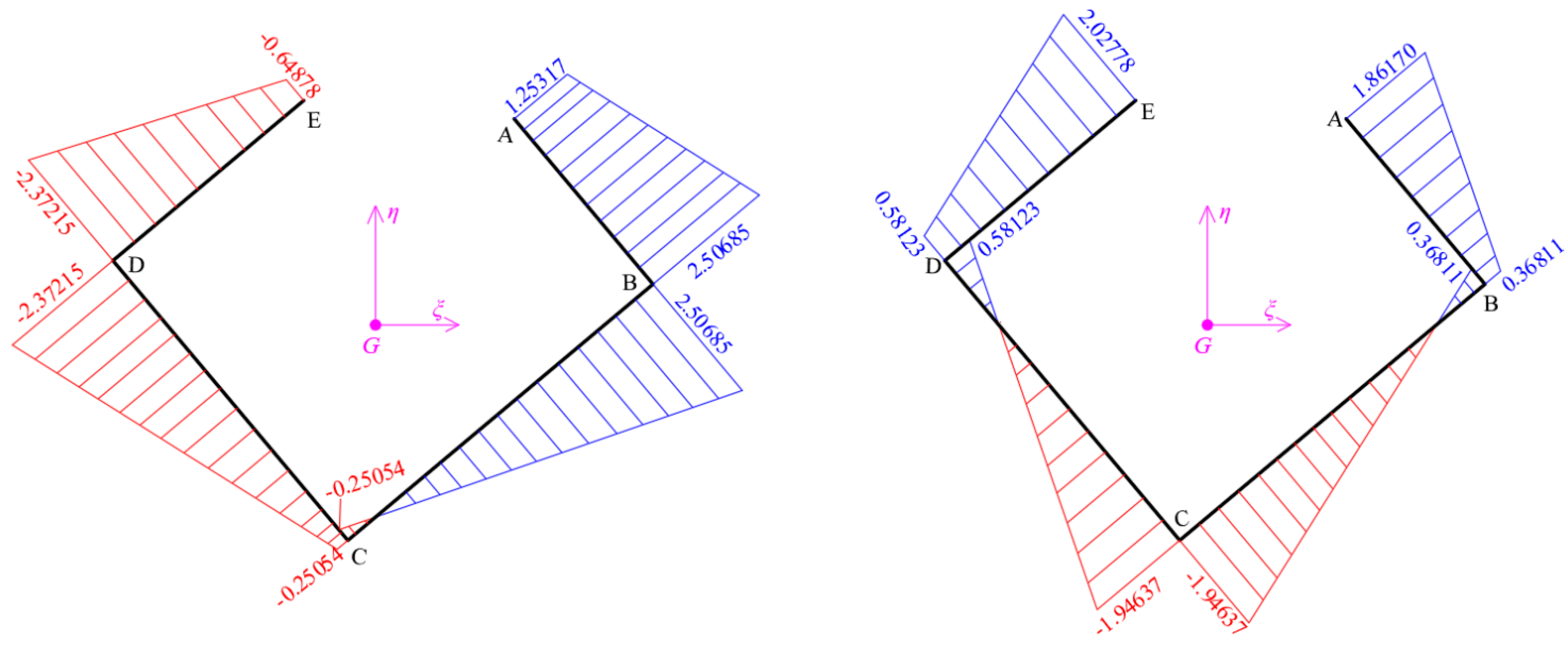
The diagrams of the functions of the coordinates ξ ( s ) ,   η ( s ) of the thin-walled cross-section referring to G ξ η z arise geometrically, or alternately analytically using the rotation matrix R (Figure 6).
Hence, the rotation matrix R is given:
R = [ cos ω ο sin ω ο sin ω ο cos ω ο ] = [ 0.765940 0.642912 0.642912 0.765940 ]
For example, at the examined core, the point A has coordinates at Cartesian reference 3D-system Gxyz:
A ( x , y ) = ( 2.15676 ,   0.62027 ) = A ( { x y } )
However, in local Cartesian 3D-system G ξ η z (that is rotated per angle ω ο = 40.00932   ο ), the coordinates of the point A in matrix form are given:
A ( { ξ η } ) = [ cos ω ο sin ω ο sin ω ο cos ω ο ] { x y } A ( { ξ η } ) = [ 0.765940 0.642912 0.642912 0.765940 ] { 2.15676 0.62027 } = { 1.25317 1.86170 }
In Figure 10 the diagrams of coordinates ξ ( s ) ,   η ( s ) are shown.

4.4. Elastic Center (Center of Stiffness) K of the Thin-Walled Cross-Section. Iterate Procedure for the Exact Location of Center K
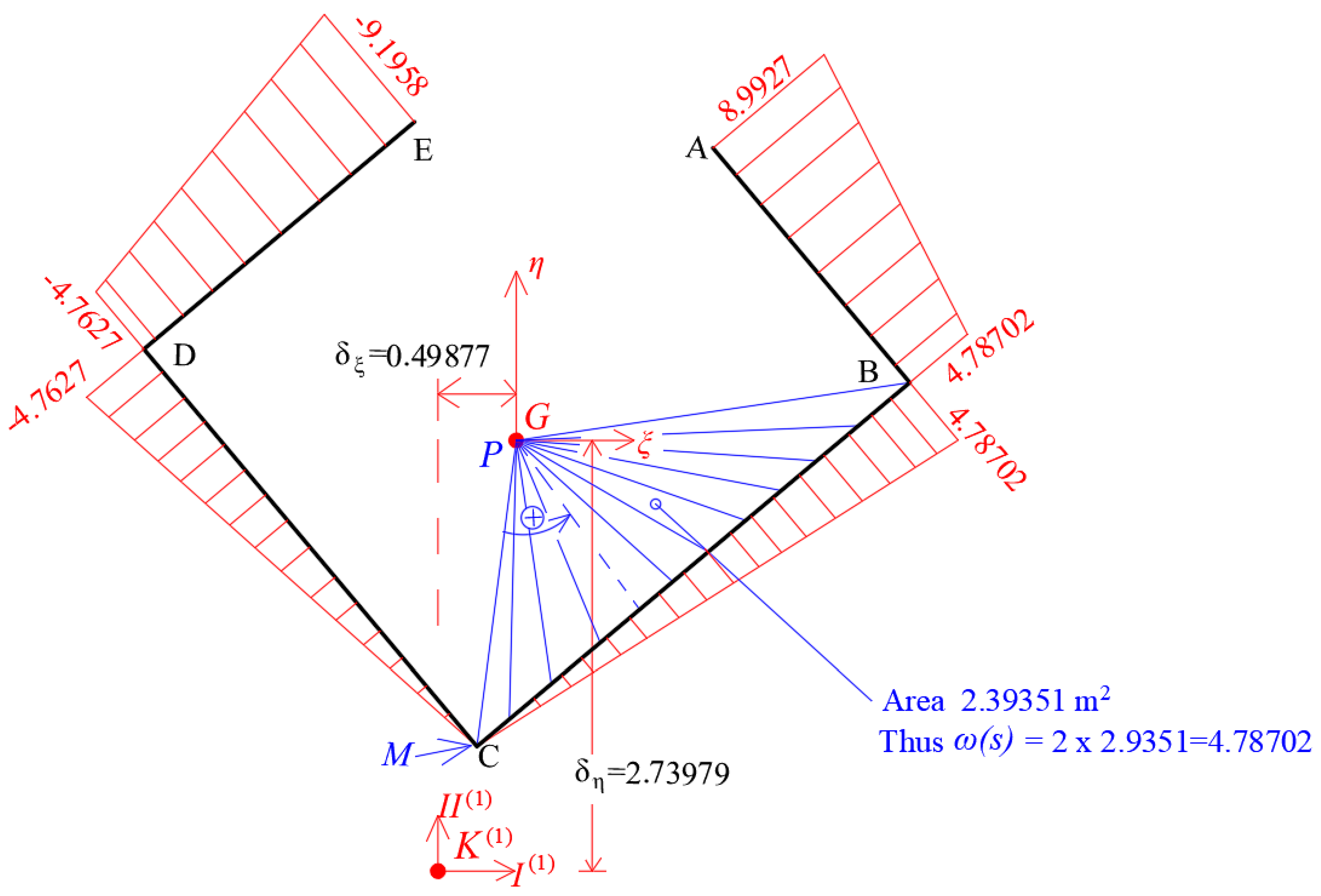
The location of the elastic center K of the thin-walled open cross-section is calculated applying the repeated procedure that is proposed by the present article, using Equations (22) and (23).
First   attempt :   Elastic   Center   K ( 1 )
The elastic center K of the thin-walled cross-section appears eccentricity, referring to pole P that coincides with the gravity center G, that is defined by the distances δ ξ and δ η from the point G along the principal directions ξ and η . Hence, in the first approximation, the calculations of the product warping moments I η , ω , I ξ , ω have been inserted into Table 3 and Table 4, while the location of the elastic center K ( 1 ) is given, (Figure 11):
Figure 11. Diagram of sectorial coordinates ω ( s ) ( 1 ) referring to pole P based at temporary start point M at corner C. The location of the elastic center K ( 1 ) of the first approximation. (Note: the exponent number indicates the number of approximation).
Buildings 12 01804 g011
Table 3. Calculation of product warping moment of inertia I η , ω on the first attempt.
Function ξ(s)Function ω(s)
NumbereLiabcdIη,ω,i
(Figure 3)
B-A0.301.952.506851.253174.787028.992707.320465
C-B0.303.60−0.250542.506850.4.787024.104242
C-D0.303.30−0.25054−2.372150.−4.762703.925162
D-E0.302.25−2.37215−0.64878−4.76270−9.195806.686042
Sum 22.035912
Table 4. Calculation of product warping moment of inertia I ξ , ω on the first attempt.
Function η(s)Function ω(s)
NumbereLiabcdIξ,ω,i
(Figure 3)
B-A0.301.950.368111.861704.787028.992704.799927
C-B0.303.60−1.946370.368110.4.78702−1.042735
C-D0.303.30−1.946370.581230.−4.762700.616029
D-E0.302.250.581232.02778−4.76270−9.19580−6.506244
Sum −2.133022
δ ξ = I ξ , ω I ξ = 2.133022 4.27656 = 0.49877   m
δ η = I η , ω I η = 22.035912 8.04292 = 2.73979   m
Second   attempt : Elastic   Center   K ( 2 )
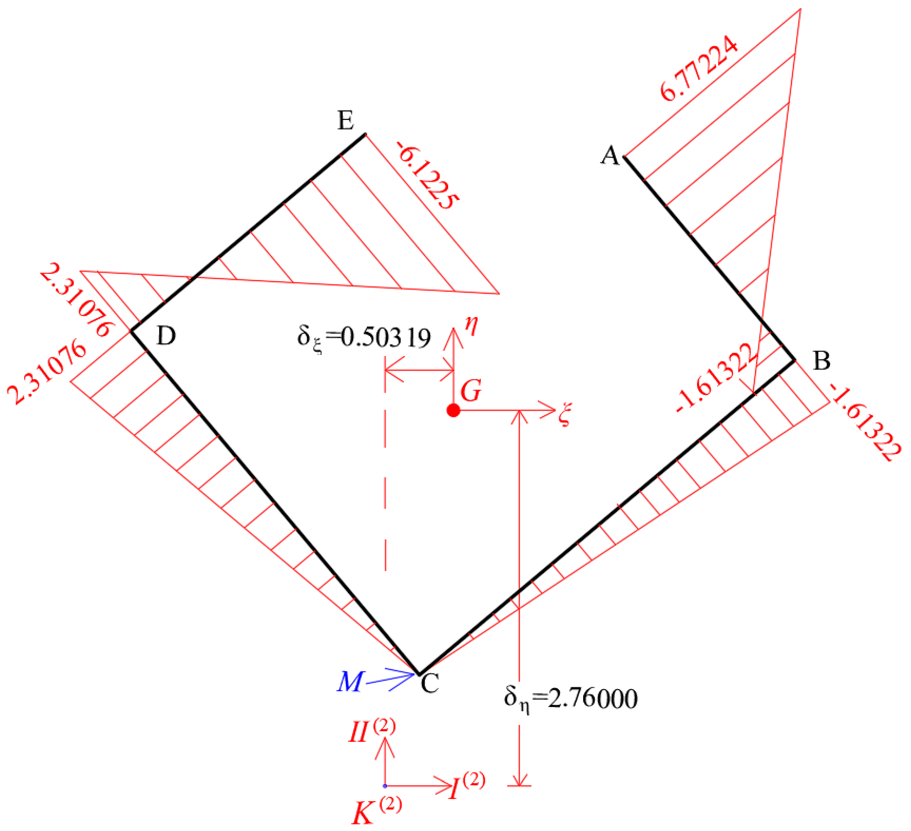
At the second iteration, as pole P the elastic center of the first attempt, K ( 1 ) is used that just has been calculated, using the same temporary start point M (which coincides at corner C) of the thin-walled open cross-section. In this second iteration, the diagram of sectorial coordinates ω ( s ) ( 2 ) of the cross-section based at temporary start point M, is given in Figure 12.
In the second approximation, the calculations of the product warping moments I η , ω , I ξ , ω have been inserted into Table 5 and Table 6, while the location of the elastic center K ( 2 ) is given, (Figure 12 and Figure 13).
Hence, in a second approximation, the location of the elastic center K ( 2 ) referring to pole P (that coincides with the point K ( 1 ) ) is given by (Figure 12):
δ ξ ( 2 ) = I ξ , ω I ξ = 0.01892 4.27656 = 0.00442   m
δ η ( 2 ) = I η , ω I η = 0.16258 8.04292 = 0.02021     m
Hence, the corrected location of elastic center from the gravity center G is given geometrically (Figure 12):
δ ξ = 0.49877 + δ ξ ( 2 ) = 0.49877 + ( 0.00442 ) = 0.50319   m
δ η = 2.73979 + δ η ( 2 ) = 2.73979 + ( 0.02021 ) = 2.76000     m
The accuracy that has been achieved is very good and hence third iteration is not needed.

4.5. Calculation of the Principal Start Point Μ ο of the Thin-Walled Open Cross-Section of the Core
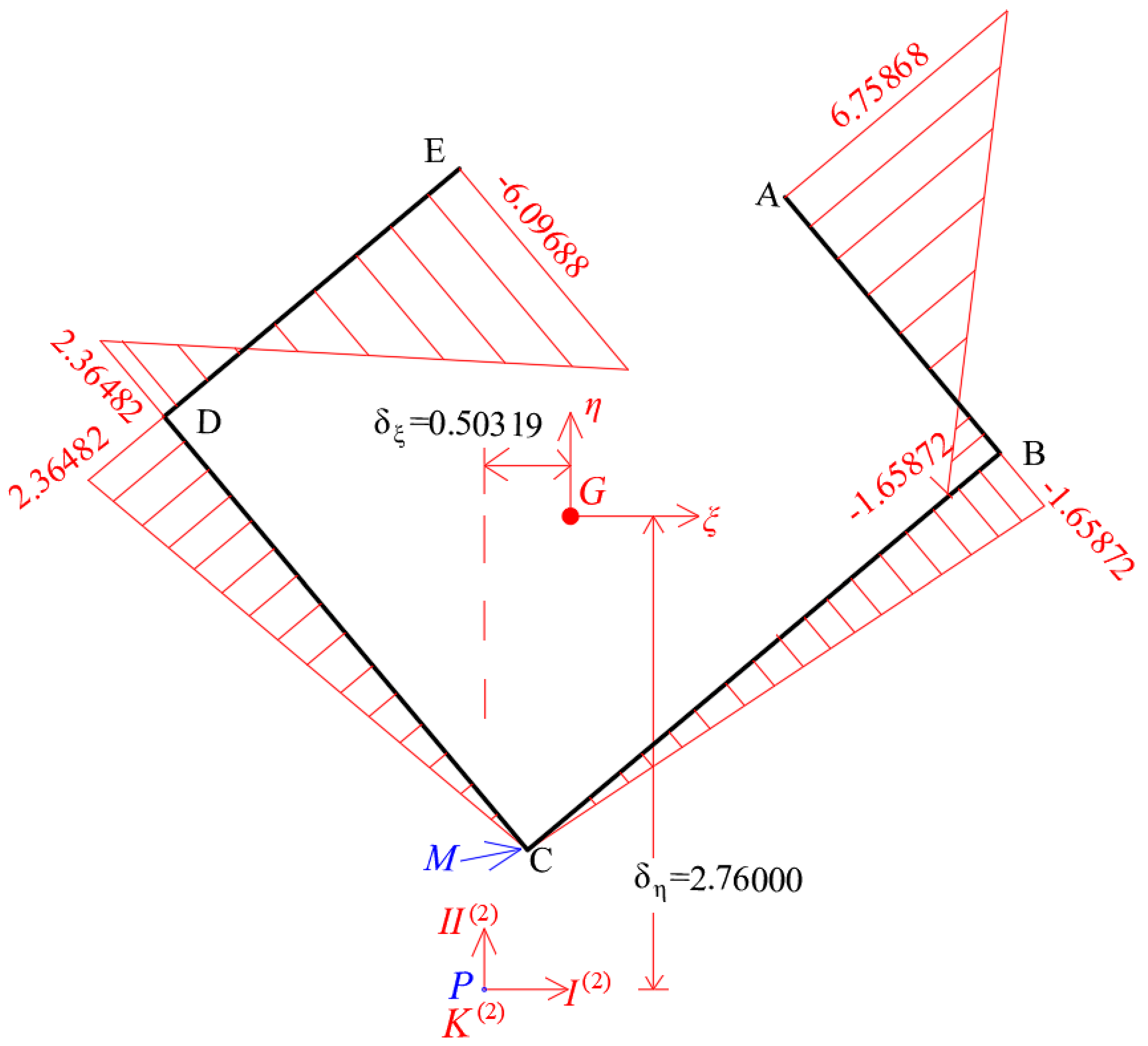
Using Equations (24)–(27) the location of the principal start point Μ ο of the examined section is calculated as following. First of all, the diagram of the sectorial coordinates ω ( s ) ( Μ ) (Table 7) has to be corrected based on the final location of the elastic center K ( 2 ) , (Figure 13):
Figure 13. The corrected diagram of the sectorial coordinates ω ( s ) ( Μ ) based on the pole P that coincides with the final location of the elastic center K ( 2 ) , using the temporary start point M at corner C.
Buildings 12 01804 g013
Table 7. Calculation of the area of the sectorial coordinates ω ( s ) ( Μ ) based at temporary start point M.
Function ω(s)
Number eLiab C e   · ω ( s ) ( Μ )   d s
B-A0.301.95−1.658726.758681.491738
C-B0.303.600−1.65872−0.89571
C-D0.303.3002.364821.170586
D-E0.302.252.36482−6.09688−1.25957
Sum 0.507045
Ω ( ρ ) = 1 A t o t · C e ( s ) · ω ( s ) ( Μ )   d s = 0.507045 3.33 = 0.152266
The height υ of the triangle Κ Μ Μ 0 can be measured geometrically as 0.71661 m, hence the distance ρ is given by the following relationship (Figure 14):
ρ = 2 A υ = Ω ( ρ )   υ = 0.152266 0.71661 = 0.21248   m
Afterwards, the final corrected diagram of the sectorial coordinates ω ( s ) has to been calculated, based on the pole P (that coincides with the final elastic center K ( 2 ) ) and based on the principal start point M o , (Figure 15).
Figure 14. Calculation of the principal start point M o of the thin-walled open cross-section.
Buildings 12 01804 g014
Figure 15. The final corrected diagram of the sectorial coordinates ω ( s ) based on the one hand on the pole P (that coincides with the final elastic center K ( 2 ) ) and on the other hand based on the principal start point M o of the thin-walled open cross-section.
Buildings 12 01804 g015

4.6. Warping Moment of Inertia I ω of the Thin-Walled Open Cross-Section

The warping moment of inertia I ω is calculated from Equation (21), while all calculations have been inserted into Table 8.
Hence I ω = 0 A ω ( s ) 2   d A = 16.39462   m 6 .
We can see in Figure 16, the Cartesian, principal, elastic 3D-system (K,I,II,III) of the thin-walled cross-section of the core with reference to initial, temporary OXYZ system, where the vertical III-axis is passed through elastic center K and together with the two horizontal K,I and K,II-axes consist the principal elastic reference system of the core.

4.7. Lateral Static Loading on the Core

We consider that the total height of the examined core ABCDE with thin-walled open cross-section is H t o t = 24.00   m . Additionally, we consider that this vertical cantilever core is loaded with three separate static loadings (Figure 17):
(i)
A lateral force F I = 10,000.00   kN applying on the top of the core on the elastic center K of the section, along the principal I-axis.
(ii)
A lateral force F I I = 10,000.00   kN applying on the top of the core on the elastic center K of the section, along the principal II-axis.
(iii)
A torsional moment M I I I = 10,000.00   kN m applying on the top of the core about the vertical III-axis of the section.
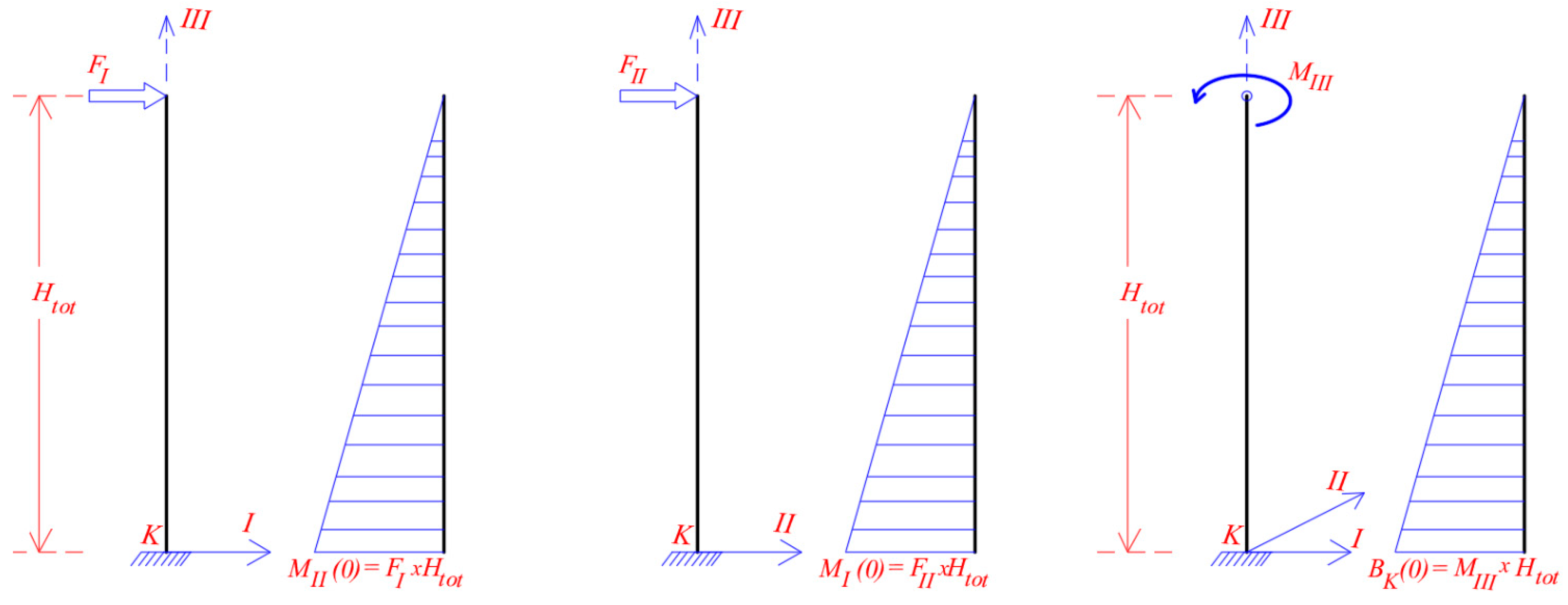
The examined core has similarities as a vertical (stick) cantilever (Figure 18). Hence, the external moment at cantilever’s base (namely for z = 0.00), about the principal I and II-axis are given as:
Μ I I ( 0 ) = F I × H t o t = 10,000.00 × 24.00 = 240,000.00   kN m = M η ( 0 )
Μ I ( 0 ) = F I I × H t o t = 10,000.00 × 24.00 = 240,000.00   kN m = M ξ ( 0 )
Hence the bi-moment B K ( 0 ) at base (z = 0.00) of the core due to torsional moment M I I I (about III-axis) is:
B K ( 0 ) = M I I I × H t o t = 10,000.00 × 24.00 = 240,000.00   kN m 2
Figure 17. The three loadings F I , F I I and M I I I applied on the elastic center K of the thin-walled cross-section along its principal axes.
Buildings 12 01804 g017
Figure 18. The diagrams of the bending moments M I and M I I due to lateral static forces F I and F I I as well as the diagram of the bi-moments Β Κ ( z ) of the core due to torsional moment M I I I at the top of the core.
Buildings 12 01804 g018
Therefore, the normal stresses σ z ( z , s ) of the core cross-section at the core’s base, due to the simultaneous action of the three above-mentioned loadings, are calculated directly by Equation (22), having in mind that the first term is null because axial loading on the core does not exist, ( N ( z ) = 0 ):
σ z ( z , s ) = N ( z ) A ξ ( s ) · M η ( z ) I η + η ( s ) · M ξ ( z ) I ξ ω ( s ) · B K ( z ) I ω
Point A of the cross-section at base (z = 0):
σ z ( 0 , A ) = ξ ( s ) · M η ( 0 ) I η + η ( s ) · M ξ ( 0 ) I ξ ω ( s ) · B K ( 0 ) I ω
σ z ( 0 , A ) = ( 1.25317 ) · 240,000 8.0429244 + ( 1.86170 ) · 240,000 4.2765553 ( 6.6064 ) · 240,000 16.39462
σ z ( 0 , A ) = ( 37,394.46 ) + ( 104,478.48 ) ( 96,710.75 ) = 238,583.69   kN / m 2
Point B of the cross-section at base (z = 0):
σ z ( 0 , B ) = ξ ( s ) · M η ( 0 ) I η + η ( s ) · M ξ ( 0 ) I ξ ω ( s ) · B K ( 0 ) I ω
σ z ( 0 , B ) = ( 2.50685 ) · 240,000 8.0429244 + ( 0.36811 ) · 240,000 4.2765553 ( 1.8110 ) · 240,000 16.39462
σ z ( 0 , B ) = ( 74,804.13 ) + ( 20,658.31 ) ( 26,511.14 ) = 68,951.30   kN / m 2
Point C of the cross-section at base (z = 0):
σ z ( 0 , C ) = ξ ( s ) · M η ( 0 ) I η + η ( s ) · M ξ ( 0 ) I ξ ω ( s ) · B K ( 0 ) I ω
σ z ( 0 , C ) = ( 0.25054 ) · 240,000 8.0429244 + ( 1.94637 ) · 240,000 4.2765553 ( 0.15228 ) · 240,000 16.39462
σ z ( 0 , C ) = ( 7476.09 ) + ( 109,230.16 ) ( 2229.22 ) = 118,935.47   kN / m 2
Point D of the cross-section at base (z = 0):
σ z ( 0 , D ) = ξ ( s ) · M η ( 0 ) I η + η ( s ) · M ξ ( 0 ) I ξ ω ( s ) · B K ( 0 ) I ω
σ z ( 0 , D ) = ( 2.37215 ) · 240,000 8.0429244 + ( 0.58123 ) · 240,000 4.2765553 ( 2.21256 ) · 240,000 16.39462
σ z ( 0 , D ) = ( 70,784.70 ) + ( 32,618.59 ) ( 32,389.55 ) = 70,555.66   kN / m 2
Point E of the cross-section at base (z = 0):
σ z ( 0 , E ) = ξ ( s ) · M η ( 0 ) I η + η ( s ) · M ξ ( 0 ) I ξ ω ( s ) · B K ( 0 ) I ω
σ z ( 0 , E ) = ( 0.64878 ) · 240,000 8.0429244 + ( 2.02778 ) · 240,000 4.2765553 ( 6.24914 ) · 240,000 16.39462
σ z ( 0 , E ) = ( 19,359.53 ) + ( 113,798.88 ) ( 91,480.84 ) = 2958.51   kN / m 2
Consequently, the normal stresses on an open-section are given by superposition of the normal stresses due to axial forces and the normal stresses due to flexural moment about the first principal axis, the normal stresses due to flexural moment about the second principal axis, and the normal stresses due to warping moment according to Vlassov torsion theory (Vlassov [1,2]; Nitti et al. [31]).
The numerical example that has been presented here can be used for the evaluation of various simulations of the core with thin-walled open cross-section, using finite shell elements, or finite solid elements, or types of equivalent frame models with reference to final location of the elastic center (or center of stiffness) of the core, as well as on normal stresses on the cross-section at the base of the core. Indeed, the cross-section that has been examined here, has known location of the elastic center, known principal directions and three separated static loadings about the principal axes. However, many different ways of simulation using finite shell elements can give very big differences from the exact theoretical solution (that come from Vlasov torsion theory) as has been presented. The comparison of the results obtained from different simulations is out of the scope of the present paper.

5. Conclusions

In the present paper, a new iterate methodology for the exact determination of the stiffness center (or elastic center) of cores has been presented. Furthermore, the determination of the principal directions of the thin-walled open cross-section of cores and its principal start point have also been presented. Last, but not least, the calculation of the corrected diagram of the sectorial coordinates and the warping moment of inertia of this section, based on the pole of the elastic center and on the principal start point have been given too. The present methodology is based on the Vlasov torsion theory of the thin-walled open cores. From the present paper, the following properties of the principal elastic Cartesian reference 3D-system K,I,II,III have arisen:
(i)
If a lateral static force F is applying on the elastic center K of a thin-walled open cross-section (having random orientation), then the rotation θ z about the vertical III-axis is null, hence the point K is center of the bending of the cross-section.
(ii)
If a torsional moment M I I I (about the vertical III-axis) is applying on the elastic center K of a thin-walled open cross-section of core, then the horizontal displacements u I and u I I of the point K are null, hence the point K is the center of twist of the cross-section.
(iii)
For a random lateral static force F that is acting on any point of the thin-walled open cross-section, and if we consider that the rotation θ z (about the vertical axis) of the cross-section has been fixed, then the equivalent base shear-force of the cross-section is passed through point K. Hence, the point K is the center of shear of the thin-walled open cross-section.
(iv)
The product warping moments of inertia I ξ , ω and I η , ω are always null, with regard to the principal elastic Cartesian reference 3D-system K,I,II,III. In a similar way, the product moment of inertia I ξ η is always null, with reference to the center-gravity Cartesian reference 3D-system G ξ η z .
(v)
If a lateral static force F I is applying on the elastic center K of a thin-walled open cross-section having the same orientation with I-axis, then the cross-section is moving parallel to itself along the I-axis, while along the II-axis the displacement is null. For this reason, the I-axis is called principal I-Axis of the cross-section.
(vi)
If a lateral static force F I I is applied on the elastic center K of a thin-walled open cross-section having the same orientation with II-axis, then the cross-section is moving parallel to itself along the II-axis, while along the I-axis the displacement is null. For this reason, the II-axis is called principal II-Axis of the cross-section.
(vii)
If there is an axis of symmetry at the cross-section, then it is always principal axis of the cross-section.
(viii)
If a lateral static force F I that is applying on the elastic center K of a thin-walled open cross-section (hence the rotation θ z about the vertical axis is null) and this force rotating slowly (to do not develop inertia forces) about the vertical axis K,III for 360 degrees, then the trace in plan of the point K displacement is forming an ellipse.
(ix)
If on the thin-walled open cross-section acts a bending moment Μ ξ about the principal center-gravity G ξ -axis, then pure bending is developing as it defined by the Bernoulli’s bending technical theory of beams, hence, the normal stresses σ z ( z , s ) are developed on total cross-section (Equation (16)).
(x)
If on the thin-walled open cross-section acts a bending moment Μ η about the principal center-gravity G η -axis, then pure bending is developing as it defined by the Bernoulli’s bending technical theory of beams, hence, the normal stresses σ z ( z , s ) are developed on total cross-section (Equation (16)).
(xi)
The recovery elastic forces Q ξ , Q η are depended from the moments of inertia I ξ and I η of the core, but these forces are acting on the elastic center K of the cross-section.
(xi)
The warping moment of inertia I ω has to be calculated with regard to principal elastic Cartesian reference 3D-system K,I,II,III (and referring to principal start point M o ) where the product warping moments of inertia I ξ , ω and I η , ω are null. Only then, the value of the I ω is minimum.
(xiii)
The normal stresses σ z ( z , s ) that are developed on the thin-walled open cross-section are given by Equation (16), that combines the bi-axial bending of the beam with axial force, as has been defined by the Bernoulli’s bending technical theory, with the Vlasov torsion theory on cores with thin-walled open cross-section.
As the point K has all the above-mentioned properties, is more suitable this point to be called “elastic center” and not simply “center of shear”. All the above-mentioned properties are very useful for the assessment and the documentation of the numerical models of cores using finite elements. Moreover, using the properties of the elastic center, we can check the correctness of the numerical results of the static loading of cores. The above-mentioned properties of the elastic center can be used for new simulation ways using numerical models for cores, something that is out of the target of the present article.

Author Contributions

The two authors T.K.M. and A.A. had the same contribution. All authors have read and agreed to the published version of the manuscript.

Funding

This research received no external funding.

Informed Consent Statement

Not applicable.

Conflicts of Interest

The authors declare no conflict of interest.

References

  1. Vlasov, V.Z. Thin-Walled Elastic Bars, 2nd ed.; Fizmatgiz: Moscow, Russia, 1959. (In Russian) [Google Scholar]
  2. Vlasov, V.Z. Thin-Walled Elastic Bars, 2nd ed.; Israel Program for Scientific Translations: Jerusalem, Israel, 1961. (In English) [Google Scholar]
  3. Xenidis, H.; Morfidis, K.; Avramidis, I.E. Modeling of two-cell cores for three-dimensional analysis of multi-story buildings. Struct. Des. Tall Build. 2000, 9, 343–363. [Google Scholar] [CrossRef]
  4. Beck, H. Contribution to the Analysis of Coupled Shear Walls. ACI J. Proc. 1962, 59, 1055–1070. Available online: https://www.concrete.org/publications/internationalconcreteabstractsportal/m/details/id/7951 (accessed on 28 August 2022).
  5. MacLeod, I.A. Lateral stiffness of shear walls with openings in tall buildings. In Tall Buildings; Pergamon: London, UK, 1967; pp. 223–244. [Google Scholar]
  6. Schwaighofer, J. Ein Beitrag zum Windscheiben-Problem. Der Bauing. 1969, 44, 370–373. [Google Scholar]
  7. Schwaighofer, J.; Microys, H.F. Analysis of shear walls using standard computer programs. ACI J. Proc. 1969, 66, 1005–1007. [Google Scholar]
  8. Heidebrecht, A.C.; Swift, R.D. Analysis of Asymmetrical Coupled Shear Walls. J. Struct. Div. 1971, 97, 1407–1422. [Google Scholar] [CrossRef]
  9. MacLeod, I. Analysis of shear wall buildings by the frame method. Proc. Inst. Civ. Eng. 1973, 55, 593–603. [Google Scholar] [CrossRef]
  10. MacLeod, I.A.; Green, D.R. Frame Idealization for Shear Wall Systems; The Structural Engineer: London, UK, 1973; Volume 51, pp. 71–74. Available online: https://www.istructe.org/journal/volumes/volume-51-(published-in-1973)/issue-2/frame-idealization-for-shear-wall-support-systems/ (accessed on 28 August 2022).
  11. MacLeod, I. General frame element for shear wall analysis. Proc. Inst. Civ. Eng. 1976, 61, 785–790. [Google Scholar] [CrossRef]
  12. MacLeod, I.A.; Hosny, H.M. Frame Analysis of Shear Wall Cores. J. Struct. Div. 1977, 103, 2037–2047. [Google Scholar] [CrossRef]
  13. MacLeod, I.A. Structural Analysis of Wall Systems; The Structural Engineer: London, UK, 1977; Volume 55, pp. 487–495. [Google Scholar]
  14. Smith, B.S.; Abate, A. Analysis of non-planar shear wall assemblies by analogous frame. Proc. Inst. Civ. Eng. 1981, 71, 395–406. [Google Scholar] [CrossRef]
  15. Lew, I.P.; Narov, F. Three-Dimensional Equivalent Frame Analysis of Shear Walls. Concr. Int. Des. Constr. 1983, 5, 25–30. Available online: https://www.concrete.org/publications/internationalconcreteabstractsportal/m/details/id/15106 (accessed on 28 August 2022).
  16. Smith, B.S.; Girgis, A. Simple Analogous Frames for Shear Wall Analysis. J. Struct. Eng. 1984, 110, 2655–2666. [Google Scholar] [CrossRef]
  17. Kheyroddin, A.; Abdollahzadeh, D.; Mastali, M. Improvement of open and semi-open core wall system in tall buildings by closing of the core section in the last story. Int. J. Adv. Struct. Eng. 2014, 6, 67. [Google Scholar] [CrossRef] [Green Version]
  18. Girgis, A.M.; Stafford-Smith, B. Torsion analysis of building cores partially closed by beams. In Proceedings of the Symposium on the Behaviour of Building Systems and Components, Vanderbilt University, Nashville, TN, USA, 8–9 March 1979; pp. 211–227. [Google Scholar]
  19. Stafford-Smith, B.; Girgis, A.M. Deficiencies in the Wide Column Analogy for Shear Wall Core Analysis. Concr. Int. 1986, 58–61. Available online: https://www.concrete.org/publications/internationalconcreteabstractsportal.aspx?m=details&i=9586 (accessed on 28 August 2022).
  20. Avramidis, I.E. Zur Kritik des Aquivalenten Rahmenmodells fur Wandscheiben und Hochhauskerne. Bautechnik 1991, 68, S275–S285. Available online: https://pascal-francis.inist.fr/vibad/index.php?action=getRecordDetail&idt=19854325 (accessed on 28 August 2022).
  21. Carpinteri, A.; Lacidogna, G.; Nitti, G. Open and closed shear-walls in high-rise structural systems: Static and dynamic analysis. Curved Layer. Struct. 2016, 3, 154–171. [Google Scholar] [CrossRef] [Green Version]
  22. Zulli, D. A one-dimensional beam-like model for double-layered pipes. Int. J. Non-Linear Mech. 2019, 109, 50–62. [Google Scholar] [CrossRef]
  23. Latalski, J.; Zulli, D. Generalized Beam Theory for Thin-Walled Beams with Curvilinear Open Cross-Sections. Appl. Sci. 2020, 10, 7802. [Google Scholar] [CrossRef]
  24. Alsheikh, A.M.S.; Rees, D.W.A. General Stiffness Matrix for a Thin-Walled, Open-Section Beam Structure. World J. Mech. 2021, 11, 205–236. [Google Scholar] [CrossRef]
  25. Choi, I.S.; Jang, G.-W.; Choi, S.; Shin, D.; Kim, Y.Y. Higher order analysis of thin-walled beams with axially varying quadrilateral cross sections. Comput. Struct. 2017, 179, 127–139. [Google Scholar] [CrossRef]
  26. Chuong, N.T.; Quy, D.X. On the Thin-Walled Theory’s Application to Calculate the Semi-enclosed Core Structure of High-Rise Buildings. In Modern Mechanics and Applications; Tien Khiem, N., Van Lien, T., Xuan Hung, N., Eds.; Lecture Notes in Mechanical Engineering; Springer: Singapore, 2022. [Google Scholar] [CrossRef]
  27. Lee, J. Center of gravity and shear center of thin-walled open-section composite beams. Compos. Struct. 2001, 52, 255–260. [Google Scholar] [CrossRef]
  28. Pavazza, R.; Matoković, A.; Vukasović, M. A theory of torsion of thin-walled beams of arbitrary open sections with influence of shear. Mech. Based Des. Struct. Mach. 2022, 50, 206–241. [Google Scholar] [CrossRef]
  29. Yu, W.; Hodges, D.H.; Volovoi, V.V.; Fuchs, E.D. A generalized Vlasov theory for composite beams. Thin-Walled Struct. 2005, 43, 1493–1511. [Google Scholar] [CrossRef]
  30. Bernuzzi, C.; Montanino, A.; Simoncelli, M. Torsional behaviour of thin-walled members with regular perforation systems. ce/papers 2021, 4, 343–350. [Google Scholar] [CrossRef]
  31. Nitti, G.; Lacidogna, G.; Carpinteri, A. Structural Analysis of High-rise Buildings under Horizontal Loads: A Study on the Piedmont Region Headquarters Tower in Turin. Open Constr. Build. Technol. J. 2019, 13, 81–96. [Google Scholar] [CrossRef]
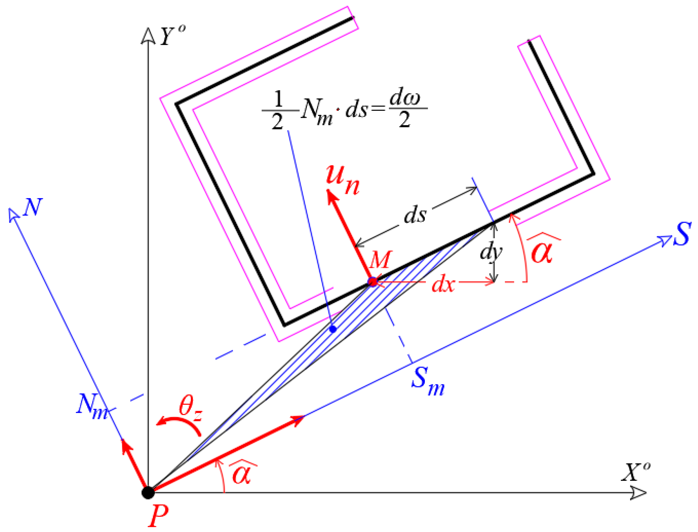
Figure 3. The natural meaning of the sectorial coordinate. In this figure, the sectorial coordinate d ω ( s ) has negative sign because the radius PM is rotated on the contrary direction from the positive rotation of a clockwised-screw about the vertical Z-axis.
Buildings 12 01804 g003
Figure 7. Plan of core with thin-walled open cross-section. Calculation of the gravity center G of the cross-section as well as the principal directions ξ and η. Note: the numbers in brackets indicate the x and y-coordinates of the gravity center of each area Ai at Cartesian reference system OXYZ.
Buildings 12 01804 g007
Figure 8. Diagrams of coordinates x ( s ) ,   y ( s ) referring to local Cartesian reference 3D-system Gxyz.
Buildings 12 01804 g008
Figure 10. Diagrams of coordinates ξ ( s ) ,   η ( s ) referring to G ξ η z .
Buildings 12 01804 g010
Figure 12. Diagram of sectorial coordinates ω ( s ) ( 2 ) referring to pole P (that coincides with point K ( 1 ) ) based at temporary start point M at corner C. The location of the elastic center K ( 2 ) of the second approximation. (Note: the exponent number indicates the number of approximation).
Buildings 12 01804 g012
Figure 16. The location of the Cartesian, principal, elastic reference system K,I,II,III in the plan of the cross-section of the core.
Buildings 12 01804 g016
Table 1. Calculating of the gravity center G of the cross-section of the core.
Numberbxby A i X i Y i X i A i Y i A i
A10.302.100.635.601.903.5281.197
A23.300.300.993.801.003.7620.990
A30.303.601.082.002.652.1602.862
A42.100.300.633.204.302.0162.709
Sum A t o t = 3.33 11.4667.758
where bx is the x-dimension of Ai area (i = 1, 2, 3, 4), by is the y-dimension of Ai area, while X i and Y i are the coordinates of the gravity center of each Ai area referring to OXYZ Cartesian reference system and Atot = ΣAi.
Table 5. Calculation of new product warping moment of inertia I η , ω in the second iteration.
Function ξ(s)Function ω(s)
NumbereLiabcdIη,ω
(Figure 3)
B-A0.301.952.506851.25317−1.613226.772242.32447
C-B0.303.60−0.250542.506850.−1.61322−1.38312
C-D0.303.30−0.25054−2.372150.2.31076−1.90440
D-E0.302.25−2.37215−0.648782.31076−6.122501.12564
Sum 0.16258
Table 6. Calculation of new product warping moment of inertia I ξ , ω in the second iteration.
Function η(s)Function ω(s)
NumbereLiabcdIξ,ω
(Figure 3)
B-A0.301.950.368111.86170−1.613226.772242.29297
C-B0.303.60−1.946370.368110.−1.613220.35140
C-D0.303.30−1.946370.581230.2.31076−0.29888
D-E0.302.250.581232.027782.31076−6.12250−2.36440
Sum I ξ , ω =
−0.01892
Table 8. Calculation of warping moment of inertia I ω based on pole of elastic center K and referring to principal start point M o of the cross-section.
Function ω(s)Function ω(s)
NumbereLiabcdIωi
(Figure 3)
B-A0.301.95−1.8116.6064−1.8116.60646.81721
C-B0.303.60−0.15228−1.811−0.15228−1.8111.28833
C-D0.303.30−0.152282.21256−0.152282.212561.51196
D-E0.302.252.21256−6.249142.21256−6.249146.77713
Sum I ω = 16.39462
Publisher’s Note: MDPI stays neutral with regard to jurisdictional claims in published maps and institutional affiliations.