Abstract
Central air-conditioning systems play a significant role in the demand response (DR) strategies of buildings due to their high energy consumption and flexible energy use. Previous simulation-based studies have shown that the use of phase change materials (PCM) in building envelopes can substantially increase cold storage capacity, which is a key measure for improving the DR performance of buildings. In this study, we experimentally investigated the effect of passive PCM walls on DR performance and conducted quantitative experiments on factors affecting the precooling performance of PCM walls. During DR events, compared to Ordinary walls without a precooling and DR stage, passive PCM walls reduced room cooling loads by 75.05%, electricity consumption by 49.57%, and peak electricity consumption by 31.06%. Additionally, in the precooling period, the impact of the room precooling temperature on passive PCM precooling performance was experimentally studied. When the room precooling temperature was reduced gradually from 21.14 °C to 18.24 °C, the precooling period could be significantly shortened by between 14.58 and 40.43%, and the room cooling load firstly increased and then decreased, during which the cooling load reduction was up to 13.87%.
1. Introduction
As the proportion of distributed energy resources in the electricity grid continues to increase, power generation capacity will increasingly be subject to uncontrollable factors, which will affect grid reliability [1]. Furthermore, the intermittency and uncertainty of renewable energy supply will intensify peak-to-valley differences in the grid, resulting in significant energy waste.
A smart grid improves reliability, economy, and sustainability by optimizing the behavior of providers and consumers [2]. In the 1980s, the Electric Power Research Institute, an American independent research and development organization, proposed demand-side management (DSM) [3] as an effective method for balancing the power grid [4]. Demand response (DR) plans are a key feature of smart grids and provide financial incentives for grid users to adjust their consumption to reduce operating costs [5,6]. DR applications result in peak shaving, enhanced capacity, and additional methods of operational control and regulation to improve the reliability of power grids [7].
Buildings are extremely energy intensive, accounting for 40% of the world’s energy consumption [8]. Building heating, ventilating, and air-conditioning (HVAC) systems are the best resources for DR strategies for three reasons. First, heating and cooling systems are the most energy-consuming elements of buildings, accounting for up to 70% of energy consumption on hot days [9,10,11]. Second, the thermal storage capacity of building envelopes can regulate the energy use of HVAC systems flexibly. Third, the centralized control feature of most HVAC systems offers the potential for the implementation of DR strategies.
There are three main strategies for DR in HVAC systems [12]:
- Global Temperature Adjustment (GTA): Buildings can achieve flexible energy consumption by adjusting the HVAC setpoint, such as by adjusting the set temperature of rooms during a DR event following enough precooling.
- System Regulation: This directly controls the HVAC system to reduce energy demand and change energy consumption, such as reducing the number of working fan coil units or turning off some of the main cooling units.
- Load Rebound Control: This includes progressively resuming energy consumption or extending a DR event.
The system regulation strategy can immediately reduce energy demand by reducing the number of energy-consuming devices (e.g., pumps, water chillers, etc.), thereby effectively responding to an urgent DR event in a smart grid. Wang et al. [13] evaluated the results of shutting down some of the operating chillers in an HVAC system for fast DR and achieved a 39% power reduction. Cui et al. [14] reduced chiller power demand by up to 34.9% by shutting down the chillers during a DR event using a fast DR response strategy involving a combination of active and passive building cold storage. Nevertheless, a fast DR strategy requires more complex controls and can affect system stability [15].
The GTA strategy, by comparison, can effectively reduce energy demand during DR events by simply adjusting the indoor air setpoint temperature [13,16,17,18]. The GTA strategy decreases building energy demand by reducing both transient and steady-state energy consumption [19]. Transient energy saving is mainly achieved at the start of a DR event. When the air temperature setpoint is set to a higher value on summer days, the HVAC system will automatically reduce or even turn off the cooling output, greatly reducing energy consumption. As the time goes on and the indoor temperature goes up, the HVAC system will gradually release cooling to stabilize the indoor temperature. However, because the air temperature is set to a higher value, the indoor-outdoor temperature difference is reduced; therefore, indoor cooling demand is lower, leading to continuous energy saving. Yoon [20] found that residential HVAC peak loads can be reduced by 24.7% and cost saving by up to 10.8% annually can be achieved using only temperature regulation. Aduda [21] achieved a 25% peak load reduction for 20 min by increasing the set temperature by 2 °C during a DR event. Kang et al. [22] achieved a 26.8% reduction of energy consumption during a DR event by regulating the temperature of an indoor HVAC system.
The strategy of precooling or preheating building envelopes to participate in grid DR events has been widely studied [23,24,25]. Precooling utilizes off-peak or cheaper electricity at night to reduce the internal heat of a building. The cold stored in walls or other interior structures of the building is released during on-peak periods to reduce the electrical consumption of the HVAC system and shift peak consumption [26]. Studies have shown that heavy walls (HW) have a higher heat capacity than light walls (LW) [27]. Hu et al. [23] employed the model predictive control (MPC) method to adjust the start-up time and duration of preheating for a floor heating system under different weather and electricity price conditions. The test results showed that the MPC controller can realize automatic preheating of the floor heating system and can reduce energy consumption during peak periods. It can also reduce electricity costs by between 1.82 and 18.65% for residential end-users. Xu et al. [28] used precooling and GTA in a commercial building with medium walls (MW) to shift 80–100% of the cooling electrical load from on-peak to off-peak periods. Chen et al. [24] applied the passive cooling storage of indoor furniture and the building envelope for GTA DR strategies. The results showed that the strategies were effective for short-term (0.5 h) and intermediate-term (2 h) DR events.
Using PCM to enhance the thermal mass performance of buildings has been widely studied in recent years, and the use of PCM in building envelopes provides opportunities for improving DR performance [29,30]. Energy can be transferred between the PCM and indoor air and the process of the physical phase change with PCM can store energy. When the room temperature drops and reaches the melting point of the PCM, cooling capacity can be transferred from the PCM to the building interior. Rahimpour et al. [31] conducted a simulation study of buildings in major Australian cities using the software EnergyPlus. They found that the application of PCM in light wall (LW) buildings has the potential to reduce the HVAC energy demand and achieve peak load shifting. Saffari et al. [25] used PCM-enhanced envelopes, and the DR simulation results showed that PCM-enhanced envelopes had the best cooling demand shifting and energy flexibility efficiency. Kishore et al. [26] studied PCM-integrated walls in a residential building and discovered that precooling between 3 and 6 a.m. can reduce the maximum heat gain during the peak period by 46% in the summer.
In summary, existing studies have found that the precooling of the building envelope followed by participation in DR events can effectively reduce energy consumption during peak periods and shift the peak load. PCM has been proven to be able to improve the latent heat capacity of building envelopes, especially for LW buildings, to increase their possibility of participating in DR events [25]. However, most of the existing research on PCM-integrated DR methods was conducted based on software simulations. There is a lack of experimental studies on the effects of passive PCM on DR in commercial buildings, especially in the precooling stage that significantly affects overall DR performance.
Thus, we combined PCM with LW and studied the effects of passive PCM on DR performance in a real experimental platform. Additionally, the precooling temperature was quantitatively studied, which is the dominant influence factor on the precooling performance of PCM walls. The effects of different precooling temperatures on the precooling time and energy consumption during the precooling period were comprehensively investigated.
2. Methodology
2.1. Experimental Platform
2.1.1. Outline of the Experimental Platform
The experimental platform included a room with PCM walls, a room with Ordinary walls, and other equipment. As shown in Figure 1, both walled rooms were LW enclosure structures (5.0 m long, 1.8 m wide, and 2.2 m high) constructed from fireproof asbestos sheets (density: 120 , conductivity: 0.043 , specific heat: 0.75 ) with a thickness of 5 cm. Each room had a door (0.7 m wide and 1.8 m high) and a single-glazed window (1.0 m wide and 1.0 m high). The mass of each experimental room was 216 kg and the heat capacity was 162 kJ/K. The rooms had an air–water HVAC system to control temperature and humidity with a three-speed fan coil (YRFC04) mounted on top of the ceiling. Chilled water for the cooling system was provided by a fully variable frequency air-cooled cold water/heat pump unit (YVAG012RSE), a variable-frequency water pump (CHL2-4), and other equipment.
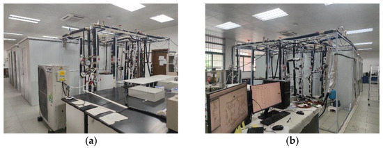
Figure 1.
The appearance of the left (a) and right (b) sides of the experimental platform, respectively.
The experimental platform was built in a separate room on a large flat floor to ensure that the experimental room was not affected by external solar radiation. Outdoor heat was provided by a heater, and indoor ambient heat was created by a heater and a humidifier.
2.1.2. Phase Change Material Walls
For this study, we selected RT25 organic solid-liquid phase change paraffin wax as the PCM based on the existing literature [32] and known properties of PCM (e.g., melting point, energy storage density, specific heat capacity, and economy). The solidification temperature of the PCM was 25.5 °C, as determined by repeated measurements in a constant-temperature water tank. The latent heat of the PCM was determined to be 200 kJ/kg by repeated measurements of energy storage density using a differential scanning calorimeter. As shown in Figure 2, we used aluminum foil bags to macro-encapsulate the same mass of PCM to make bagged PCM modules, and we then used galvanized wire to fix eight bagged PCM modules to make PCM wall modules with a top and bottom double structure. The six PCM wall modules were then structured in the upper, middle, and lower layers to form PCM walls and were combined with part of the experimental room wall sections.
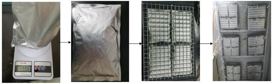
Figure 2.
PCM wall production process.
2.1.3. Data Acquisition
We monitored the cooling system data and its electricity consumption, and the surface temperature of the PCM and Ordinary walls.
The measurement devices related to this study are listed in Table 1. The water pipe temperature sensor and flow sensor were to monitor the water temperature and flow rate to calculate the cooling load, and the pressure sensor was to monitor the pressure of the water pipe branch (Figure 3). The air temperature and humidity sensor were to monitor the indoor temperature and humidity. AC voltage transmitter and AC current transmitter were to monitor the circuit current and voltage values.

Table 1.
Measurement devices and parameters.
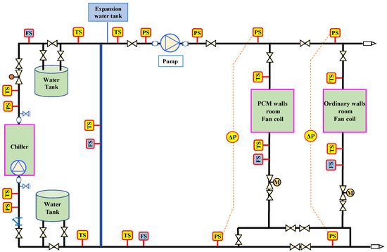
Figure 3.
Pipeline monitoring points.
The data from multiple sensors were uploaded to the Niagara Framework® software platform in real time via a building automation system. The data at each point were calibrated, located, and calculated before being saved on the platform, with data acquisition recording once every 30 s.
The surface temperatures of PCM and Ordinary walls were monitored using an Omega-type T thermocouple with an Agilent data acquisition unit, with data acquisition recording once every second. (Figure 4).
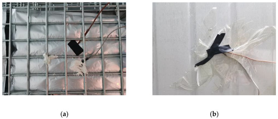
Figure 4.
Surface temperature measurement points of PCM and Ordinary wall envelopes on the left (a) and right (b), respectively.
2.2. Experimental Program
This section describes the experimental program used to study the DR performances of composite PCM walls. Figure 5 is a schematic diagram of the experimental program, which had the following aims: to investigate the effects of (1) passive PCM walls on the DR performance of a building; and (2) different precooling temperatures on the performance of passive PCM walls in the precooling stage.
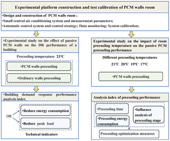
Figure 5.
Experimental schemes.
To ensure that the experiments were conducted under similar conditions, each group of experiments was selected to be conducted under similar external weather and indoor temperature conditions, and the number of heaters inside and outside the experimental room was regularly adjusted during the experimental process to achieve the purpose of simulating day and night environmental changes. After each experiment, the state of the experimental room, the PCM state, and the external state of the experimental room were restored and left to stand for more than 24 hours.
2.2.1. Demand Response Experiment
This section presents the whole procedure of the experiment used to determine the DR of passive PCM walls. The results were analyzed and compared with the results of the DR experiment for passive Ordinary walls and with the benchmark performance of Ordinary walls with no precooling or DR. The more energy that was stored in the PCM walls during precooling, the more energy would be released during the DR event. Therefore, the PCM walls were fully precooled to ensure a complete phase change in this study.
The experiment comprised two stages: the precooling stage (before 8:00), and the daily work stage (8:00–19:00) in which a four-hour GTA DR stage (13:00–17:00) was included. During precooling, the HVAC temperature in the experimental room was set to 21 °C until the PCM walls underwent a complete phase change. Immediately after the precooling stage, the experiment entered the daily work stage and the room temperature was set to 24 °C. In the GTA DR stage, the room temperature was set to 28 °C for 4 h and then turned down to 24 °C at the end of the DR event and maintained until the end of the experiment (Type A, PCM walls precooling with DR). The room temperature control strategy in the daily work stage is shown in Figure 6.
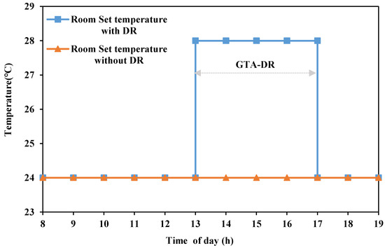
Figure 6.
Room temperature settings.
The DR experimental procedure for the Ordinary passive wall was the same as that of the passive PCM walls described above. The precooling time and the GTA DR of the Ordinary walls were also the same as those of the PCM walls (Type B, Ordinary walls with precooling and DR).
The benchmark Ordinary walls experiment consisted of a single daily work stage (8:00–19:00) during which the HVAC temperature in the experimental room was set to 24 °C and maintained until the end of the experiment. There were no precooling or DR stages in this experiment (Type C, Ordinary walls without DR).
At the end of the experiments, we compared and analyzed various aspects of the results. The technical analysis indexes used were the reduction of energy consumption and the reduction of the peak values during the DR event. The reduction of the energy consumption index refers to energy saving (i.e., cooling load and electricity consumption) in the experimental room during the DR event compared with the benchmark value of the total energy consumption. The reduction of the peak values refers to the reduction in peak electricity consumption in the experimental room during the DR event compared with the benchmark value. Positive values indicate a decrease in energy or peak energy consumption, and negative values indicate an increase in energy or peak energy consumption.
2.2.2. Impact of Precooling Temperature on Precooling Performance
The precooling stage is an important stage affecting phase change energy storage of the PCM walls. Precooling temperature is one of the key factors affecting the precooling effect. At lower temperatures, heat transfer efficiency increases, and precooling is completed within a shorter period. However, under this condition, the temperature difference between indoors and outdoors becomes greater, and heat dissipation from the internal to the external environment also increases. The precooling time and energy consumption collectively affect precooling performance; therefore, experiments exploring the effect of the precooling temperature on the performance of the precooling stage are necessary to provide a reference for optimizing the precooling procedure.
This experiment studied the precooling performance of PCM walls at different precooling temperatures (i.e., 21 °C, 20 °C, 19 °C, and 17 °C) and comparative analyses of the variations in precooling times and energy consumption were conducted. The experimental results at 21 °C were used as the benchmark value.
To more clearly show the influence of temperature on precooling time and energy consumption, in this study, we defined the unit reduction rate, which represents the reduction of precooling time and energy consumption when the precooling temperature decreases by one degree relative to the reference value. The positive value indicates a decrease and the negative value indicates an increase.
3. Results and Discussion
3.1. Impact of PCM Walls on the DR Performance of Buildings
We analyzed results throughout the whole process of the experiment in which the daily work stage of the GTA DR event was conducted with the PCM walls precooled at 21 °C. We analyzed the precooling stage, DR stage, and whole process, and compared the results with those of the Ordinary walls.
3.1.1. Precooling Stage Analysis
As shown in Figure 7, the PCM walls and Ordinary walls in the experimental rooms were precooled at 21 °C. During the precooling stage, the temperatures of both rooms were similar. After reaching the setpoint temperature from identical starting conditions, the temperatures remained stable at around 21 °C until the end of the precooling stage. The precooling time of the PCM walls in the precooling stage was 13.78 h. The cooling load of the room with PCM walls and that of the room with Ordinary walls were similar at 62,328 kJ and 62,613 kJ, respectively.
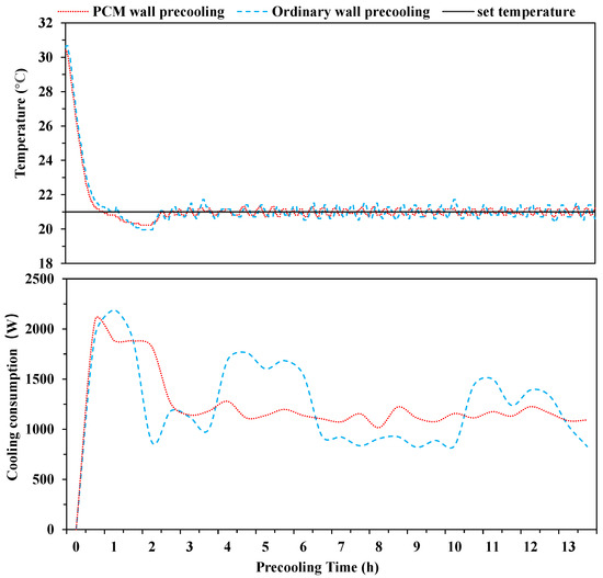
Figure 7.
Room temperature and cold consumption during the precooling stage.
3.1.2. Performance Analysis of the DR Event
Figure 8 shows the real-time temperature within the experimental rooms during the 11 h daily work stage (including the 4 h GTA-DR stage). Whether there was PCM or not, the indoor temperature could be maintained near the set value under proportion integration differentiation control and mediation, but in the stable phase, the temperature fluctuation of the PCM wall room was smaller. This is because the PCM walls increased the thermal quality of the room, and at the same time, when the indoor temperature rose above the melting temperature, they slowly released their cooling capacity to stabilize room energy consumption.
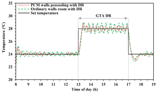
Figure 8.
Real-time temperature of experimental rooms.
Figure 9 shows the cooling and electricity consumption within the experimental rooms. In the DR stage, the experimental room with PCM walls had better performance than the room with Ordinary walls. The cooling, electricity, and peak electricity consumption values of the PCM wall room were significantly lower than those of the Ordinary wall room, indicating that PCM walls had higher DR potential. It is worth mentioning that after completing the GTA stage when the temperature was set lower, the subsequent peak rebound loads were lower in the room with PCM walls than in the room with Ordinary walls.
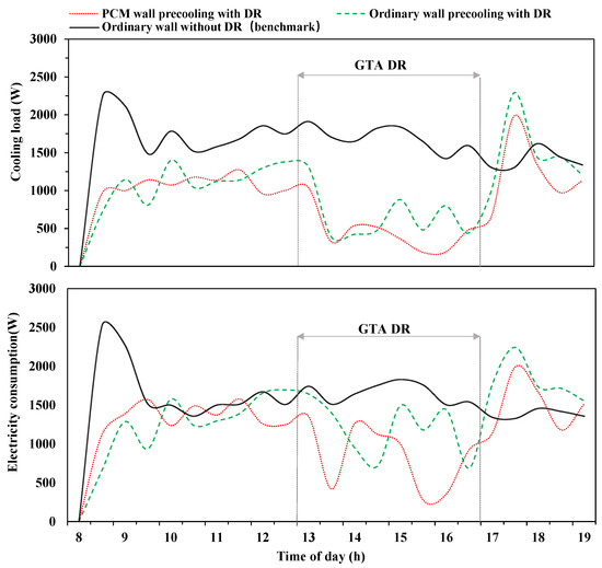
Figure 9.
Cooling load and electricity consumption of experimental rooms.
- i.
- Reducing Energy Consumption Capability
Figure 10 shows the total energy consumption of the experimental room within four hours during the demand response period (13:00–17:00) where Type C (Ordinary walls without DR) did not participate in the GTA DR event, meaning the room set temperature did not change, whereas Type B (Ordinary walls precooling with DR) and Type A (PCM walls precooling with DR) participated in GTA DR, meaning the room set temperature increased from 24 °C to 28 °C, which reduced the cooling load and electricity consumption.
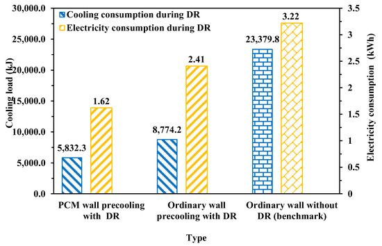
Figure 10.
Energy consumption during DR event.
Compared with the benchmark type C, type A reduced the cooling load by 75.05% and electricity consumption by 49.57%. Type B reduced the cooling load by 62.47% and electricity consumption by 25.22%. The reduction in the cooling load of type A with PCM was 12.55% higher than that of type B, and the former had a two-fold reduction in electricity consumption compared to the latter. This is because PCM walls can store more energy than Ordinary walls, and they can cool the room more effectively and continuously during DR events, thereby reducing energy demand and further increasing DR potential.
- ii.
- Peak Load Reduction
Table 2 shows that, compared to the benchmark Ordinary walls without precooling and DR, the experimental room with PCM walls reduced the peak load during the DR event by 511.69 W (31.06%). With the same precooling conditions, Ordinary walls reduced the peak load by 301.99 W (18.33%). These results indicate that PCM walls had better performance in reducing the peak load during the DR event.
Table 2.
Peak load reduction.
3.1.3. Cooling Load Analysis
Since type A (PCM walls precooling with DR) and type B (Ordinary walls precooling with DR) both underwent the precooling stage, the overall cooling load was higher (Table 3), but this reduced the cooling load during the daily work stage. Compared with the benchmark type C (the Ordinary walls without DR), the cooling load of type A was 46.8% lower and that of type B was 38.2% lower. The cooling loads of type A and type B were similar in the precooling stage, but the increase in the total cooling load of the former was less than that of the latter. In the end, the total cooling load of type A was 47.7% higher and that of type B was 56.9% higher. Although the use of precooling stages leads to higher energy consumption, this can be compensated for by lower electricity prices or the shifting of peak demand.
Table 3.
Stage cooling load.
3.2. Impact of Precooling Temperature on Precooling Performance
Precooling temperature is a key factor affecting precooling efficacy. In this section, we study the impact of different precooling temperatures (i.e., 21 °C, 20 °C, 19 °C, and 17 °C) on the precooling performance of the PCM walls in terms of precooling time and precooling energy consumption.
3.2.1. Impact of Precooling Temperature on Precooling Time
The average precooling temperature is the average temperature of the room during the precooling stage. The precooling time is the time required for the PCM walls to change from the same liquid state to the same solid state under different precooling temperatures.
The actual precooling temperatures differed from the setpoint temperatures due to the initial temperatures of the room. The setpoint temperatures were 21 °C, 20 °C, 19 °C, and 17 °C, but the corresponding actual average precooling temperatures were 21.14 °C, 20.31 °C, 19.19 °C, and 18.24 °C, respectively. In the first three groups of experiments, the deviations between the setpoint and actual temperatures were smaller; however, the actual temperature was 1.24 °C higher than the setpoint when the precooling temperature was set to 17 °C. This is because the lower the setpoint temperature was set, the more cooling was required from the fan coil units, which had a finite cooling capacity. Thus, it took a longer time for temperatures to reach and remain stable at this setpoint temperature, causing a notable deviation between the setpoint and actual average precooling temperatures.
As shown in Table 4, precooling times decreased as the precooling setpoint decreased. As the precooling setpoint was lowered from 21 °C to 17 °C, the precooling time decreased from 13.85 h to 8.25 h. As the precooling temperature decreased, the temperature difference increased, heat transfer efficiency increased, and the precooling time decreased. Using the precooling setpoint temperature of 21 °C as the benchmark for comparing precooling performance, the precooling time can be reduced by up to 40.43%. For every 1 °C decrease in the precooling temperature, the precooling time can be reduced by between 13.51 and 17.56%. There was a linear relationship between the precooling time and precooling temperature.
Table 4.
Precooling times at various precooling setpoints temperatures.
3.2.2. Impact of Precooling Temperature on Precooling Energy Consumption
As the precooling temperature decreased, its difference to the phase change solidification temperature grew, heat transfer became more efficient, and precooling speed increased, but the required energy per unit time for the room increased. The precooling time and the energy consumption speed had a coupling effect on energy consumption. The energy consumption used for the PCM wall precooling first decreased and then increased, and there was a minimum cooling load at 19 °C.
As the set temperature changes, the load rate changes, and the equipment efficiency changes. Electricity consumption is affected not only by precooling temperatures but also by system efficiency. To highlight the fact that energy consumption is only influenced by the precooling temperature, we investigated the variation of the cooling load.
Table 5 shows that, using the results of the experiment with a setpoint temperature of 21 °C as the benchmark, the cooling load in precooling first decreased and then increased. Therefore, the unit cooling decrease first increased and then decreased. Compared to the benchmark of 21 °C, at precooling temperatures of 20 °C and 19 °C, the cooling decreased by 7.73% and 13.87%, respectively. The unit cooling decreases were 9.31% and 7.11%, respectively. At the precooling setpoint temperature of 17 °C, however, cooling demand increased. The final room cooling load was only 4.52% lower than the benchmark, and the unit cooling decrease was only 1.56%.
Table 5.
Changes in precooling cooling load at various precooling temperatures.
3.2.3. Precooling Performance Discussion
To summarize, compared to the precooling experimental results at the precooling setpoint temperature of 21 °C, decreasing the precooling temperature reduced the precooling time by up to 40.43% and the cooling load by up to 13.87%. As the precooling temperature decreased, the precooling was accelerated and its duration decreased, but heat dissipation to the external environment increased due to larger temperature difference. Considering the difference between the precooling before the daily work stage and the fast precooling before the DR stage, the former had sufficient time to complete the precooling process in which the electricity price generally remains unchanged. Therefore, minimum energy consumption in achieving precooling should be considered. The latter is time limited, and the electricity price varies largely; thus, in response to the DR event, a lower precooling temperature should be used to ensure precooling performance and achieve greater DR potential during the DR event.
4. Conclusions
This study combined PCM with an LW building and experimentally evaluated the effects of PCM walls on the demand response performance in buildings. Additionally, the precooling temperature, which is the dominant factor that influences the precooling performance of PCM walls, was comprehensively investigated. The following are the main findings of this study:
- After precooling the PCM walls and the Ordinary walls at 21 °C, an 11 h daily work stage was conducted with a 4 h GTA DR stage included. The PCM walls reduced the cooling load, electricity consumption, and peak electricity consumption of the experimental room by 75.05%, 49.57%, and 31.06%, respectively. Compared to the same conditions for the Ordinary walls, the PCM walls reduced the cooling load, electricity consumption, and peak consumption by 12.58%, 24.35%, and 12.73%, respectively. Therefore, using PCM walls can increase the thermal mass of the building envelope and provide higher DR potential in a GTA DR event. Overall, using a precooling stage can lead to higher energy consumption, but this can also be compensated for by lower electricity prices or the displacement of peak demand.
- Precooling temperature greatly affected the phase change precooling time. For every 1 °C decrease, the precooling time decreased by between 13.51 and 17.56%. As the precooling temperature decreased, the temperature difference increased, the precooling speed increased, and the precooling time decreased.
- As the precooling temperature decreased, the precooling time also decreased, but the unit time energy demand of the rooms increased. Their coupling effect affected the total precooling energy consumption. The cooling load first decreased and then increased, and the maximum reduction in room cooling load was 13.87%. While lower precooling temperatures accelerated the precooling process, this also increased energy consumption. For precooling with sufficient time and unchanged electricity prices, minimum energy consumption in achieving precooling should be considered. For precooling with limited time and large variation, a lower precooling temperature should be used to ensure the adequate performance of precooling and thus reduce energy consumption and the peak load during the DR event.
As for future work, this study could be extended by considering the combination of PCM with different walls (i.e., MW and HW) to investigate the effects of PCM walls on building demand response performance after precooling in buildings with different thermal masses and the precooling performance (i.e., precooling time and energy consumption).
Author Contributions
Conceptualization, Z.Y. and D.-c.G.; methodology, Z.Y., D.-c.G. and Y.S.; formal analysis, Y.S. and D.-c.G.; investigation, S.M., W.Z. and X.Z.; writing—original draft preparation, Z.Y.; writing—review and editing, D.-c.G. and W.Z.; supervision, D.-c.G.; project administration, D.-c.G. All authors have read and agreed to the published version of the manuscript.
Funding
This research was funded by a grant from the National Natural Science Foundation of China (No. 52278133 and No. 52178091) and a grant from the Natural Science Foundation of Guangdong Province (No. 2021A1515012265).
Data Availability Statement
The data presented in this study are available on request from the corresponding author.
Acknowledgments
The authors acknowledge the contribution of all respondents and facilitators who helped in the study.
Conflicts of Interest
The authors declare no conflict of interest.
References
- Jiang, B.; Fei, Y. Dynamic Residential Demand Response and Distributed Generation Management in Smart Microgrid with Hierarchical Agents. Energy Procedia 2011, 12, 76–90. [Google Scholar] [CrossRef]
- Yuan, J.; Hu, Z. Low carbon electricity development in China—An IRSP perspective based on Super Smart Grid. Renew. Sustain. Energy Rev. 2011, 15, 2707–2713. [Google Scholar] [CrossRef]
- Gellings, C.W. Then and now: The perspective of the man who coined the term ‘DSM’. Energy Policy 1996, 24, 285–288. [Google Scholar] [CrossRef]
- Jordehi, A.R. Optimisation of demand response in electric power systems, a review. Renew. Sustain. Energy Rev. 2019, 103, 308–319. [Google Scholar] [CrossRef]
- O’connell, N.; Pinson, P.; Madsen, H.; O’malley, M. Benefits and challenges of electrical demand response: A critical review. Renew. Sustain. Energy Rev. 2014, 39, 686–699. [Google Scholar] [CrossRef]
- Wang, S.; Xue, X.; Yan, C. Building power demand response methods toward smart grid. HVAC&R Res. 2014, 20, 665–687. [Google Scholar]
- Koliou, E.; Eid, C.; Chaves-Ávila, J.P.; Hakvoort, R.A. Demand response in liberalized electricity markets: Analysis of aggregated load participation in the German balancing mechanism. Energy 2014, 71, 245–254. [Google Scholar] [CrossRef]
- Omer, A.M. Energy, environment and sustainable development. Renew. Sustain. Energy Rev. 2008, 12, 2265–2300. [Google Scholar] [CrossRef]
- Azar, A.G.; Olivero, E.; Hiller, J.; Lesch, K.; Jiao, L.; Kolhe, M.; Asanalieva, N.; Ferrez, P.; Zhang, Q.; Jacobsen, R.; et al. Algorithms for demand response and load control. SEMIAH, SEMIAH-WP5-D5 2015, 1-v0. [Google Scholar]
- He, X.; Hancher, L.; Azevedo, I.; Keyaerts, N.; Meeus, L.; Glachant, J.M. Shift, Not Drift: Towards Active Demand Response and Beyond; European University Institute: Fiesole, Italy, 2013. [Google Scholar]
- Kueck, J.D.; Ally, M.R.; Rice, C.K. Using Air Conditioning Load Response for Spinning Reserve; Oak Ridge National Laboratory: Oak Ridge, TN, USA, 2009.
- Olesen, B.W.; Brager, G.S. A Better Way to Predict Comfort: The New ASHRAE Standard 55-2004; University of California: Oakland, CA, USA, 2004. [Google Scholar]
- Wang, S.; Gao, D.C.; Tang, R.; Xiao, F. Cooling supply-based AC system control for fast demand response of buildings to urgent requests of smart grids. Energy Procedia 2016, 103, 34–39. [Google Scholar] [CrossRef]
- Cui, B.; Wang, S.; Yan, C.; Xue, X. Evaluation of a fast power demand response strategy using active and passive building cold storages for smart grid applications. Energy Convers. Manag. 2015, 102, 227–238. [Google Scholar] [CrossRef]
- Ran, F.; Gao, D.C.; Zhang, X.; Chen, S. A virtual sensor based self-adjusting control for AC fast demand response in commercial buildings towards smart grid applications. Appl. Energy 2020, 269, 115103. [Google Scholar] [CrossRef]
- Xue, X.; Wang, S.; Yan, C.; Cui, B. A fast chiller power demand response control strategy for buildings connected to smart grid. Appl. Energy 2015, 137, 77–87. [Google Scholar] [CrossRef]
- Ardito, L.; Procaccianti, G.; Menga, G.; Morisio, M. Smart Grid Technologies in Europe: An Overview. Energies 2013, 6, 251–281. [Google Scholar] [CrossRef]
- Rotger-Griful, S.; Jacobsen, R.H.; Nguyen, D.; Sørensen, G. Demand response potential of ventilation systems in residential buildings. Energy Build. 2016, 121, 1–10. [Google Scholar] [CrossRef]
- Motegi, N.; Piette, M.; Watson, D.; Kiliccote, S.; Xu, P. Introduction to Commercial Building Control Strategies and Techniques for Demand Response; LBNL-599754; Lawrence Berkeley National Laboratory: Berkeley, CA, USA, 2007.
- Yoon, J.H.; Bladick, R.; Novoselac, A. Demand response for residential buildings based on dynamic price of electricity. Energy Build. 2014, 80, 531–541. [Google Scholar] [CrossRef]
- Aduda, K.; Labeodan, T.; Zeiler, W.; Boxem, G.; Zhao, Y. Demand side flexibility: Potentials and building performance implications. Sustain. Cities Soc. 2016, 22, 146–163. [Google Scholar] [CrossRef]
- Kang, J.; Weng, S.; Li, Y.; Ma, T. Study of Building Demand Response Method Based on Indoor Temperature Setpoint Control of VRV Air Conditioning. Buildings 2022, 12, 415. [Google Scholar] [CrossRef]
- Hu, M.; Xiao, F.; Jørgensen, J.B.; Li, R. Price-responsive model predictive control of floor heating systems for demand response using building thermal mass. Appl. Therm. Eng. 2019, 153, 316–329. [Google Scholar] [CrossRef]
- Chen, Y.; Xu, P.; Chen, Z.; Wang, H.; Sha, H.; Ji, Y.; Zhang, Y.; Dou, Q.; Wang, S. Experimental investigation of demand response potential of buildings: Combined passive thermal mass and active storage. Appl. Energy 2020, 280, 115956. [Google Scholar] [CrossRef]
- Saffari, M.; Conor, R.; Donal, P.F. Improving the building energy flexibility using PCM-enhanced envelopes. Appl. Therm. Eng. 2022, 217, 119092. [Google Scholar] [CrossRef]
- Kishore, R.A.; Bianchi, M.V.; Booten, C.; Vidal, J.; Jackson, R. Modulating thermal load through lightweight residential building walls using thermal energy storage and controlled precooling strategy. Appl. Therm. Eng. 2020, 180, 115870. [Google Scholar] [CrossRef]
- Becker, R. Improving thermal and energy performance of buildings in summer with internal phase change materials. J. Build. Phys. 2013, 37, 296–324. [Google Scholar] [CrossRef]
- Xu, P.; Haves, P.; Piette, M.A.; Braun, J. Peak Demand Reduction from Pre-Cooling with Zone Temperature Reset in an Office Building; No. LBNL-55800; Lawrence Berkeley National Lab. (LBNL): Berkeley, CA, USA, 2004.
- Kant, K.; Shukla, A.; Sharma, A. Advancement in phase change materials for thermal energy storage applications. Sol. Energy Mater. Sol. Cells 2017, 172, 82–92. [Google Scholar] [CrossRef]
- Darby, S.J. Smart electric storage heating and potential for residential demand response. Energy Effic. 2017, 11, 67–77. [Google Scholar] [CrossRef]
- Rahimpour, Z.; Verbic, G.; Chapman, A.C. Energy management of buildings with phase change materials based on dynamic programming. In Proceedings of the 2019 IEEE Milan PowerTech, Milano, Italy, 23–27 June 2019. [Google Scholar]
- Wang, X.; Li, W.; Luo, Z.; Wang, K.; Shah, S.P. A critical review on phase change materials (PCM) for sustainable and energy efficient building: Design, characteristic, performance and application. Energy Build. 2022, 260, 111923. [Google Scholar] [CrossRef]


Publisher’s Note: MDPI stays neutral with regard to jurisdictional claims in published maps and institutional affiliations. |
© 2022 by the authors. Licensee MDPI, Basel, Switzerland. This article is an open access article distributed under the terms and conditions of the Creative Commons Attribution (CC BY) license (https://creativecommons.org/licenses/by/4.0/).