
Flexural Behaviour of Built-Up Beams Made of Optimised Sections
 , , and
Abstract
:
1. Introduction
2. Finite Element Modelling
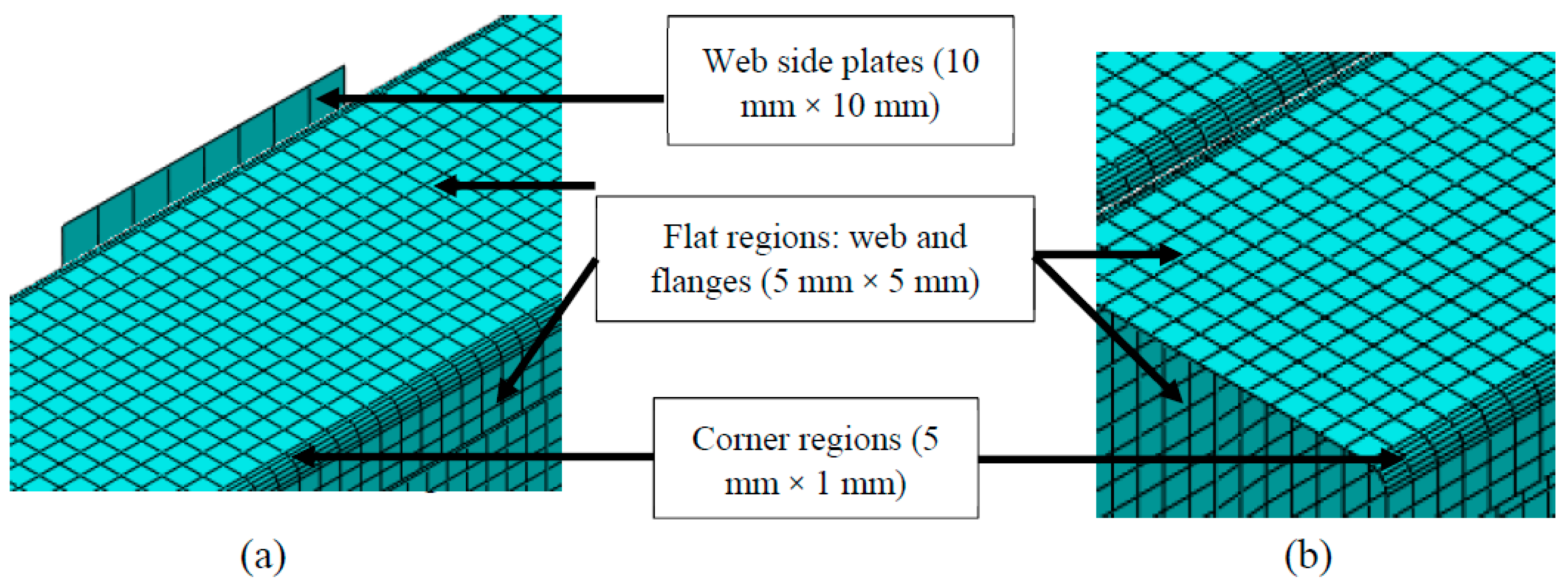
2.1. Finite Element Type and Mesh
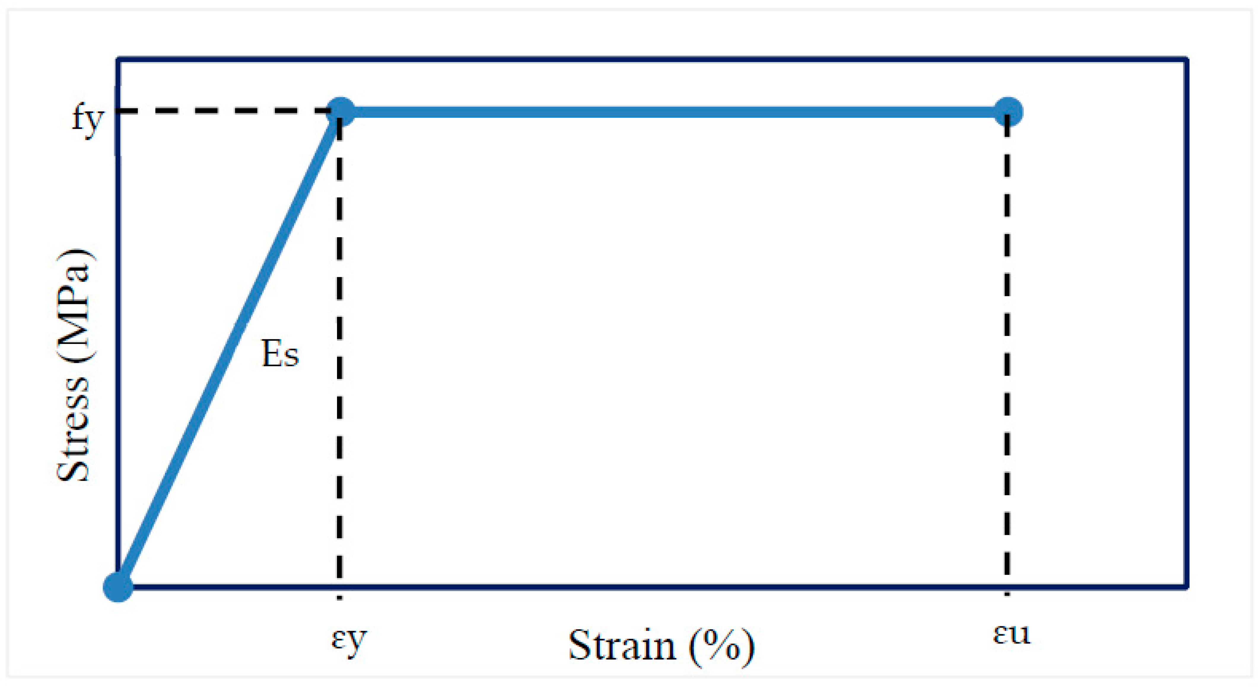
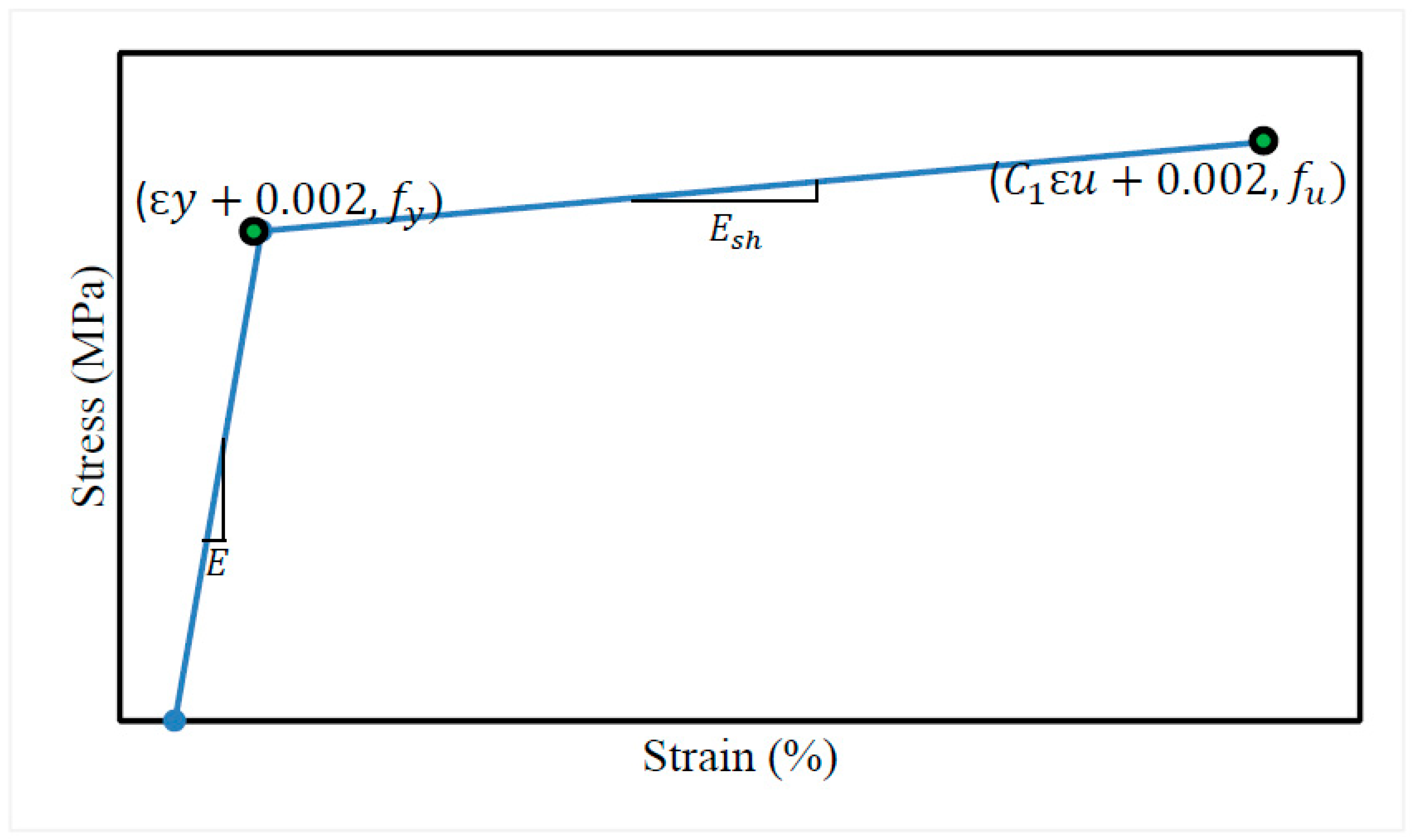
2.2. Material Modelling
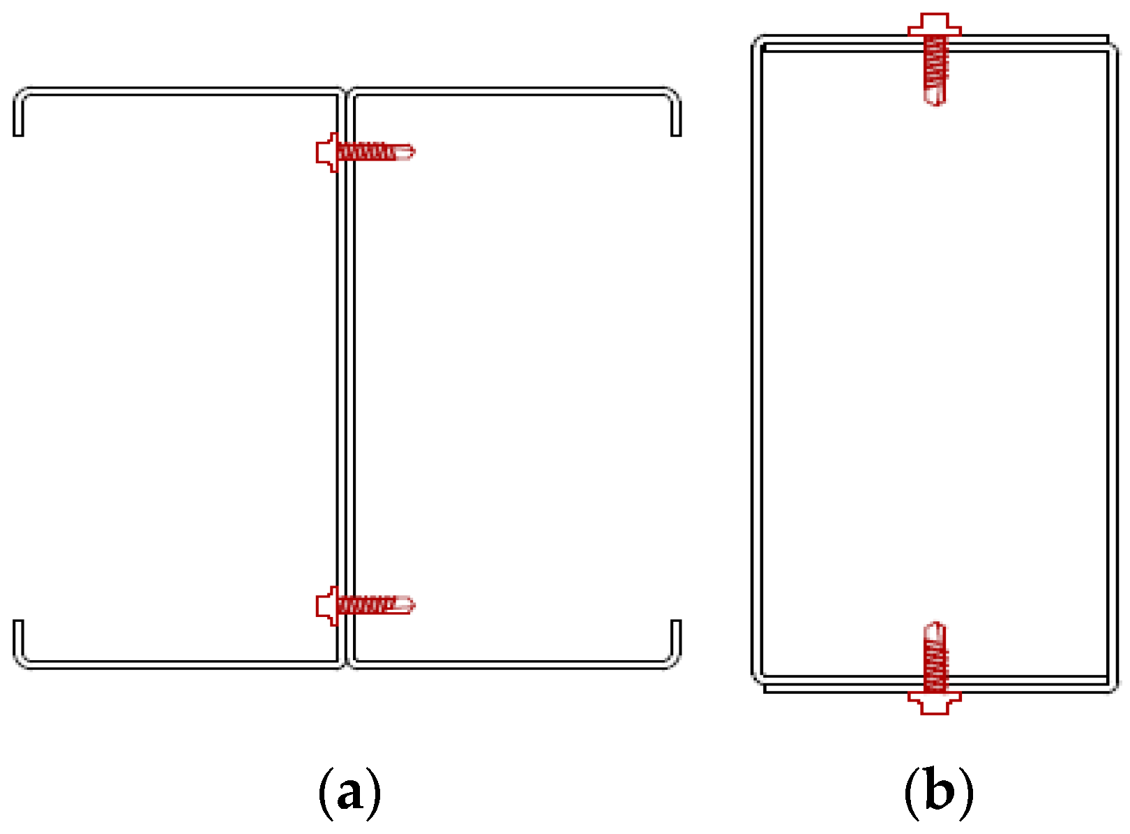
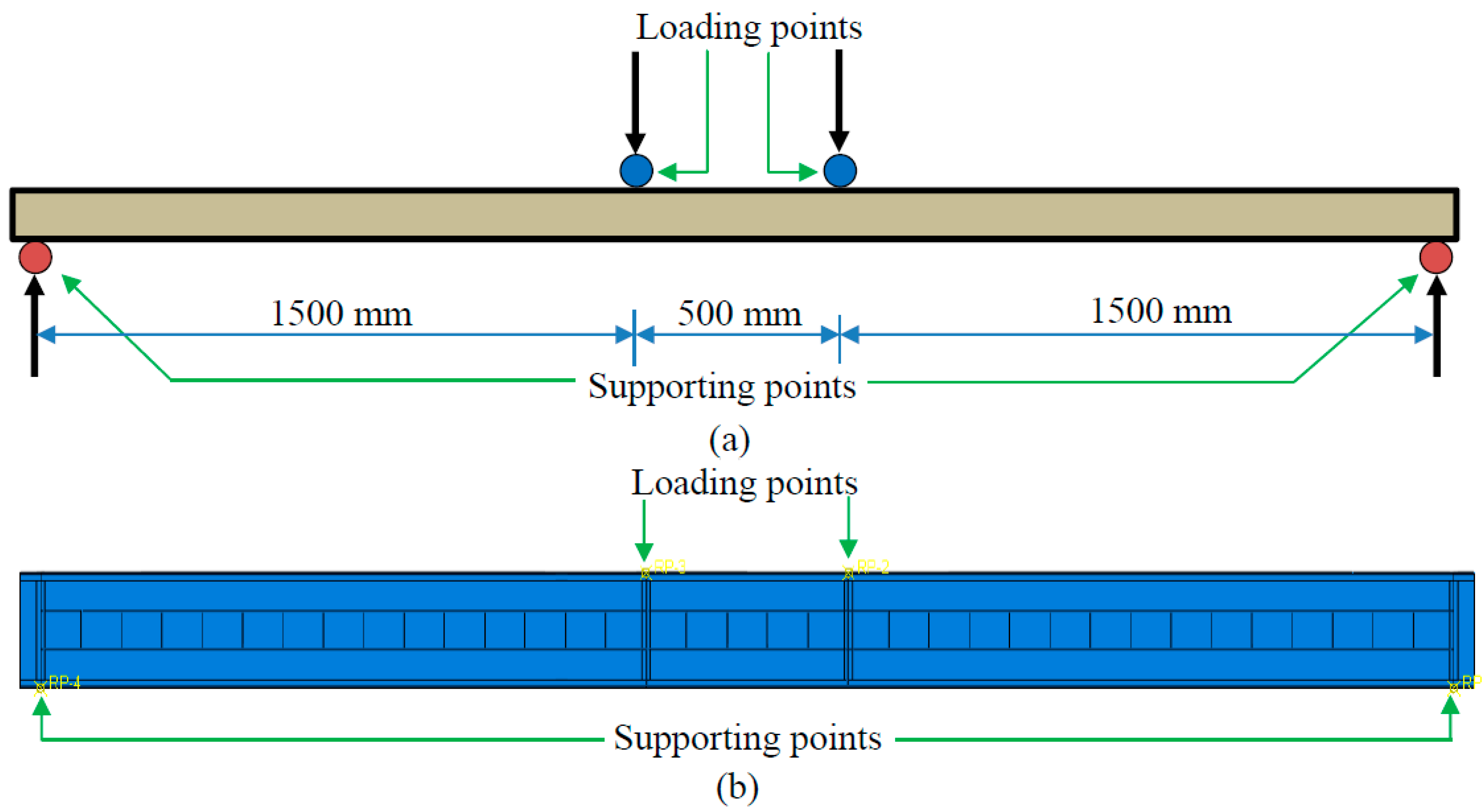
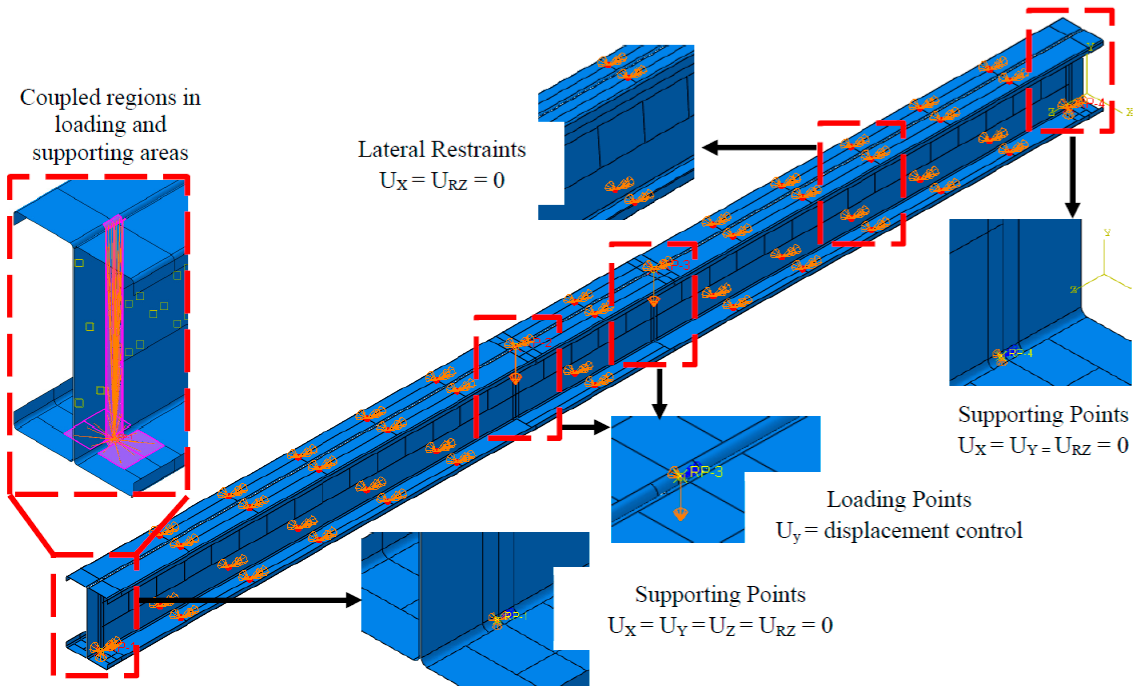
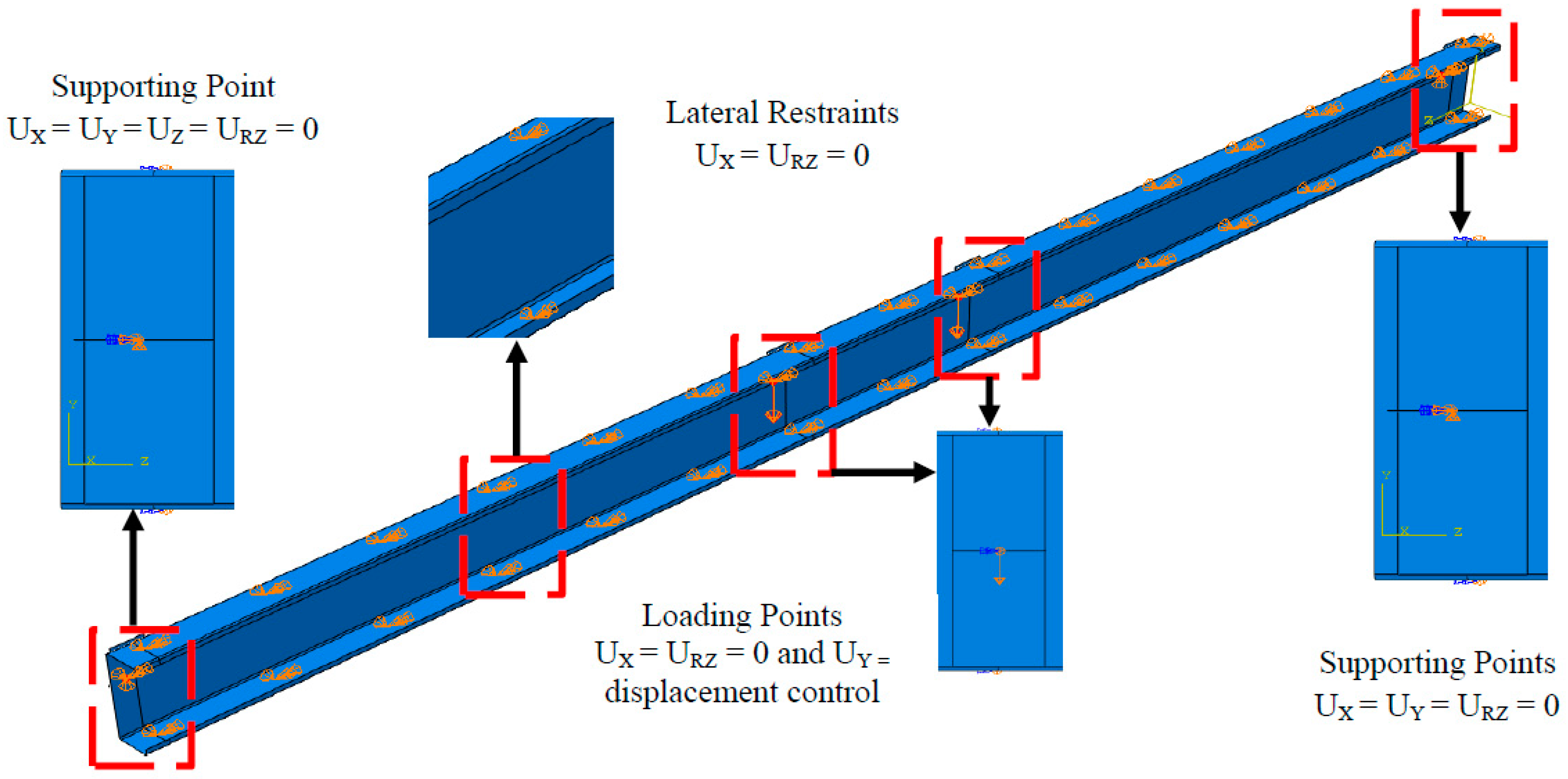
2.3. Loading and Boundary Conditions
2.4. Interaction and Properties
2.5. Solution Scheme
3. Validation and Parametric Plan
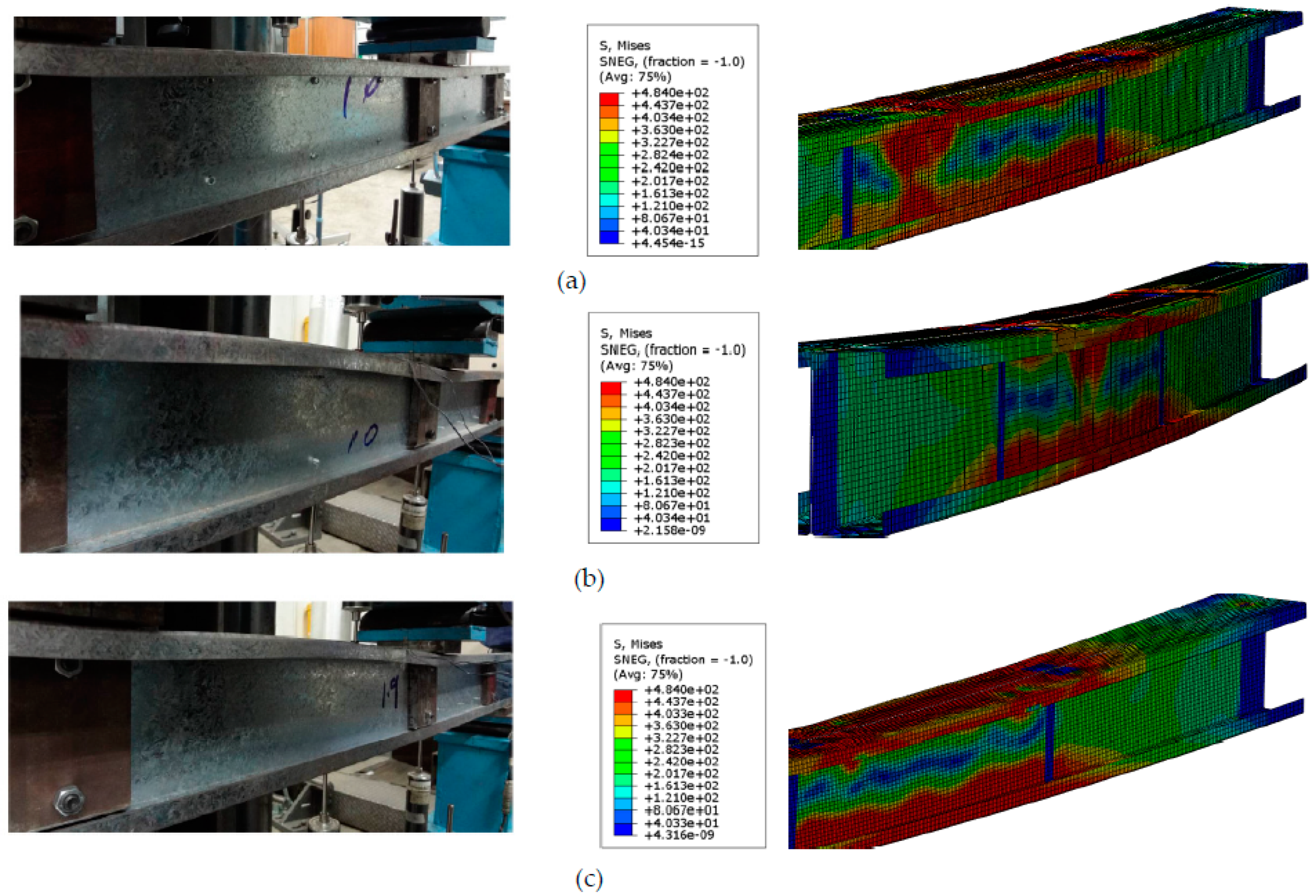
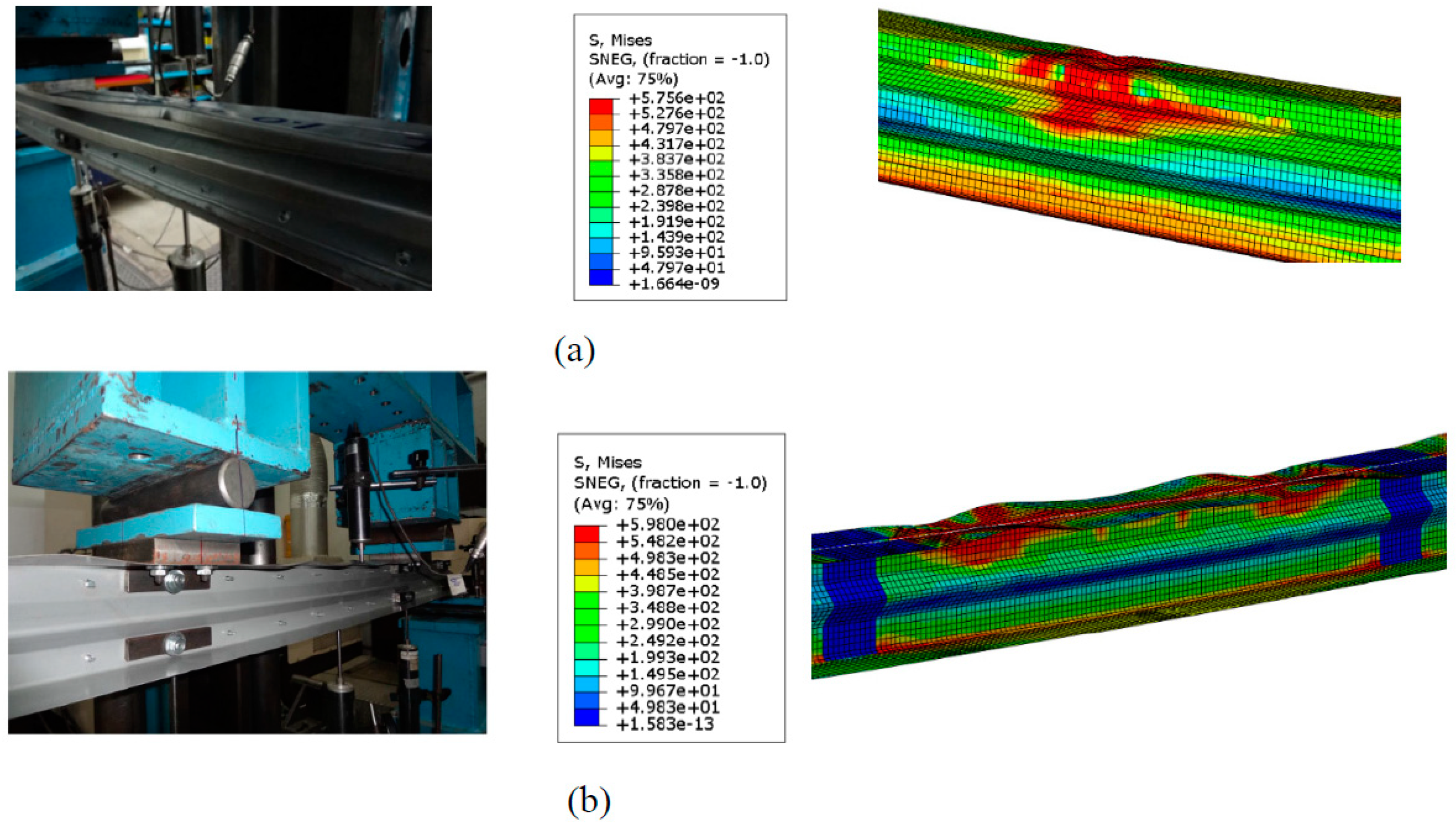
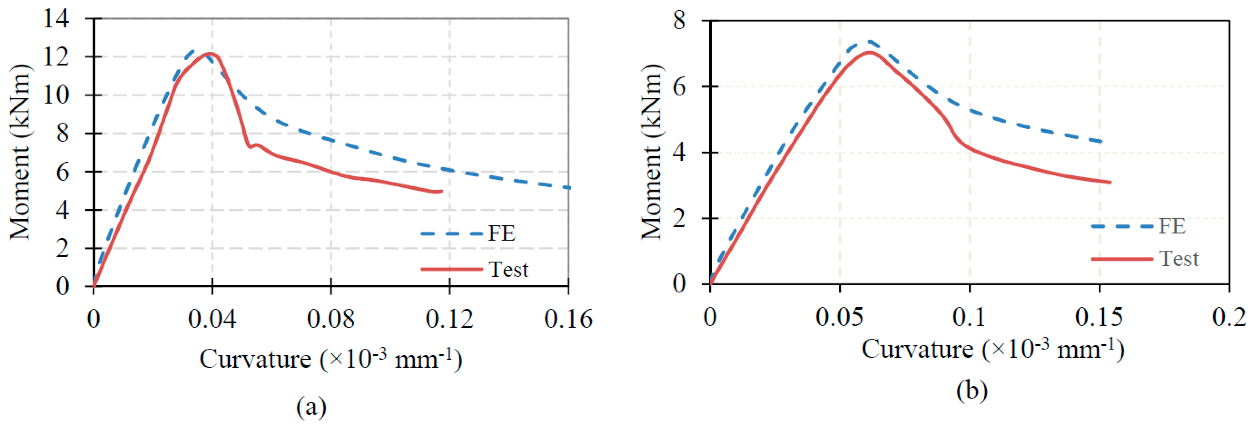
3.1. Validation of FE Models
3.2. Parametric Plan
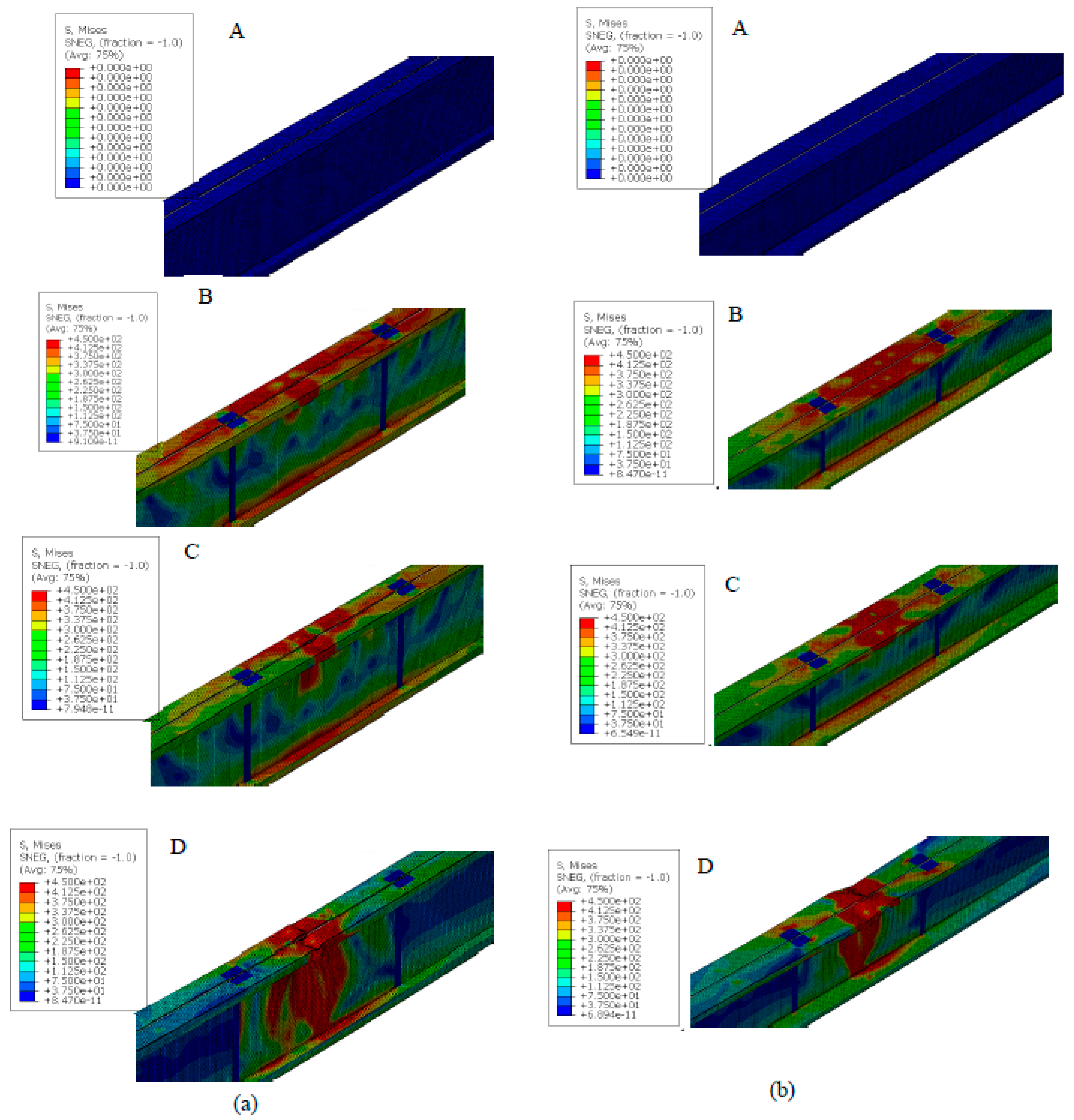
4. Results and Discussion
5. Ongoing and Future Works
6. Conclusions
Author Contributions
Funding
Institutional Review Board Statement
Informed Consent Statement
Data Availability Statement
Acknowledgments
Conflicts of Interest
References
- Wang, L.; Young, B. Behavior of Cold-Formed Steel Built-Up Sections with Intermediate Stiffeners under Bending. II: Parametric Study and Design. J. Struct. Eng. 2016, 142, 04015151. [Google Scholar] [CrossRef]
- Wang, L.; Young, B. Behavior of Cold-Formed Steel Built-Up Sections with Intermediate Stiffeners under Bending. I: Tests and Numerical Validation. J. Struct. Eng. 2016, 142, 04015150. [Google Scholar] [CrossRef]
- Li, Q.-Y.; Young, B. Experimental study on cold-formed steel built-up section beam-columns experiencing non-uniform bending. Eng. Struct. 2022, 256, 113954. [Google Scholar] [CrossRef]
- Laím, L.; Rodrigues, J.P.C.; Craveiro, H.D. Flexural behaviour of beams made of cold-formed steel sigma-shaped sections at ambient and fire conditions. Thin-Walled Struct. 2015, 87, 53–65. [Google Scholar] [CrossRef]
- Lu, Y.; Zhou, T.; Li, W.; Wu, H. Experimental investigation and a novel direct strength method for cold-formed built-up I-section columns. Thin-Walled Struct. 2017, 112, 125–139. [Google Scholar] [CrossRef] [Green Version]
- Li, Q.-Y.; Young, B. Design of cold-formed steel built-up open section members under combined compression and bending. Thin-Walled Struct. 2022, 172, 108890. [Google Scholar] [CrossRef]
- Thirunavukkarasu, K.; Kanthasamy, E.; Gatheeshgar, P.; Poologanathan, K.; Rajanayagam, H.; Suntharalingam, T.; Dissanayake, M. Sustainable Performance of a Modular Building System Made of Built-Up Cold-Formed Steel Beams. Buildings 2021, 11, 460. [Google Scholar] [CrossRef]
- Thirunavukkarasu, K.; Kanthasamy, E.; Poologanathan, K.; Tsavdaridis, K.D.; Gatheeshgar, P.; Hareindirasarma, S.; McIntosh, A. Shear performance of SupaCee sections with openings: Numerical studies. J. Constr. Steel Res. 2022, 190, 107142. [Google Scholar] [CrossRef]
- Keerthan, P.; Mahendran, M. Elastic shear buckling characteristics of LiteSteel beams. J. Constr. Steel Res. 2010, 66, 1309–1319. [Google Scholar] [CrossRef] [Green Version]
- Keerthan, P.; Mahendran, M. Experimental investigation and design of lipped channel beams in shear. Thin-Walled Struct. 2015, 86, 174–184. [Google Scholar] [CrossRef]
- Gatheeshgar, P.; Poologanathan, K.; Gunalan, S.; Nagaratnam, B.; Tsavdaridis, K.D.; Ye, J. Structural behaviour of optimized cold-formed steel beams. Steel Constr. 2020, 13, 294–304. [Google Scholar] [CrossRef]
- Pham, C.H.; Bruneau, L.A.; Hancock, G.J. Experimental Study of Longitudinally Stiffened Web Channels Subjected to Combined Bending and Shear. J. Struct. Eng. 2015, 141, 4015018. [Google Scholar] [CrossRef]
- Wang, L.; Young, B. Behaviour and design of cold-formed steel built-up section beams with different screw arrangements. Thin-Walled Struct. 2018, 131, 16–32. [Google Scholar] [CrossRef]
- Anbarasu, M. Simulation of flexural behaviour and design of cold-formed steel closed built-up beams composed of two sigma sections for local buckling. Eng. Struct. 2019, 191, 549–562. [Google Scholar] [CrossRef]
- Ye, J.; Mojtabaei, S.M.; Hajirasouliha, I.; Shepherd, P.; Pilakoutas, K. Strength and deflection behaviour of cold-formed steel back-to-back channels. Eng. Struct. 2018, 177, 641–654. [Google Scholar] [CrossRef]
- Jeyaragan, S.; Mahendran, M. Numerical Modelling and Design of the New Built-up LiteSteel Beams. In Proceedings of the Fifth International Conference on Coupled Instabilities in Metal Structures CIMS, Sydney, Australia, 23–25 June 2008. [Google Scholar]
- Xu, L.; Sultana, P.; Zhou, X. Flexural strength of cold-formed steel built-up box sections. Thin-Walled Struct. 2009, 47, 807–815. [Google Scholar] [CrossRef]
- Wang, L.; Hu, M.; Young, B. Tests of aluminum alloy perforated built-up sections subjected to bending. Thin-Walled Struct. 2021, 158, 107136. [Google Scholar] [CrossRef]
- Karthik, C.; Anbarasu, M. Cold-formed ferritic stainless steel closed built-up beams: Flexural behaviour and numerical parametric study. Thin-Walled Struct. 2021, 164, 107816. [Google Scholar] [CrossRef]
- EN 1993-1-3; Eurocode3: Design of Steel Structures, Part1.3: General Rules—Supplementary Rules for Coldformed Steel Members and Sheeting. European Committee for Standardization: Brussels, Belgium, 2005.
- SIMULIA. ABAQUS Standard User’s Manual; Version 6.14; Dassault Systèmes Simulia Corp.: Johnston, RI, USA, 2013. [Google Scholar]
- Poologanathan, K.; Mahendran, M. Numerical modelling and design of lipped channel beams subject to shear. In Proceedings of the European Conference on Steel and Composite Structures, Naples, Italy, 10–12 September 2014; pp. 445–446. [Google Scholar]
- Poologanathan, K.; Mahendran, M. Numerical modeling of litesteel beams subject to shear. J. Struct. Eng. 2011, 137, 1428–1439. [Google Scholar]
- Keerthan, P.; Mahendran, M. Shear buckling characteristics of cold-formed steel channel beams. Int. J. Steel Struct. 2013, 13, 385–399. [Google Scholar] [CrossRef] [Green Version]
- Su, M.-N.; Young, B.; Gardner, L. Testing and Design of Aluminum Alloy Cross Sections in Compression. J. Struct. Eng. 2014, 140, 04014047. [Google Scholar] [CrossRef]
- Alsanat, H.; Gunalan, S.; Poologanathan, K.; Guan, H. Web crippling investigations of aluminum lipped channel sections under one-flange loading conditions. Thin-Walled Struct. 2021, 166, 108025. [Google Scholar] [CrossRef]
- McIntosh, A.; Kanthasamy, E.; Poologanathan, K.; Gunalan, S.; Gatheeshgar, P.; Corradi, M.; Higgins, C. Web crippling design of channel beams: Carbon steel, stainless steel and aluminium. J. Constr. Steel Res. 2022, 196, 107427. [Google Scholar] [CrossRef]
- Rasmussen, K.J. Full-range stress–strain curves for stainless steel alloys. J. Constr. Steel Res. 2003, 59, 47–61. [Google Scholar] [CrossRef]
- Cruise, R.B.; Gardner, L. Strength enhancements induced during cold forming of stainless steel sections. J. Constr. Steel Res. 2008, 64, 1310–1316. [Google Scholar] [CrossRef]
- Ashraf, M.; Gardner, L.; Nethercot, D. Strength enhancement of the corner regions of stainless steel cross-sections. J. Constr. Steel Res. 2005, 61, 37–52. [Google Scholar] [CrossRef]
- Wang, L.; Young, B. Design of cold-formed steel built-up sections with web perforations subjected to bending. Thin-Walled Struct. 2017, 120, 458–469. [Google Scholar] [CrossRef]
- Yu, C.; Schafer, B.W. Simulation of cold-formed steel beams in local and distortional buckling with applications to the direct strength method. J. Constr. Steel Res. 2007, 63, 581–590. [Google Scholar] [CrossRef]
- Schafer, B.; Li, Z.; Moen, C. Computational modeling of cold-formed steel. Thin-Walled Struct. 2010, 48, 752–762. [Google Scholar] [CrossRef] [Green Version]
- Keerthan, P.; Mahendran, M.; Hughes, D. Numerical studies and design of hollow flange channel beams subject to combined bending and shear actions. Eng. Struct. 2014, 75, 197–212. [Google Scholar] [CrossRef]


| Prototypes | Single Sections [11] | Built-Up Sections |
|---|---|---|
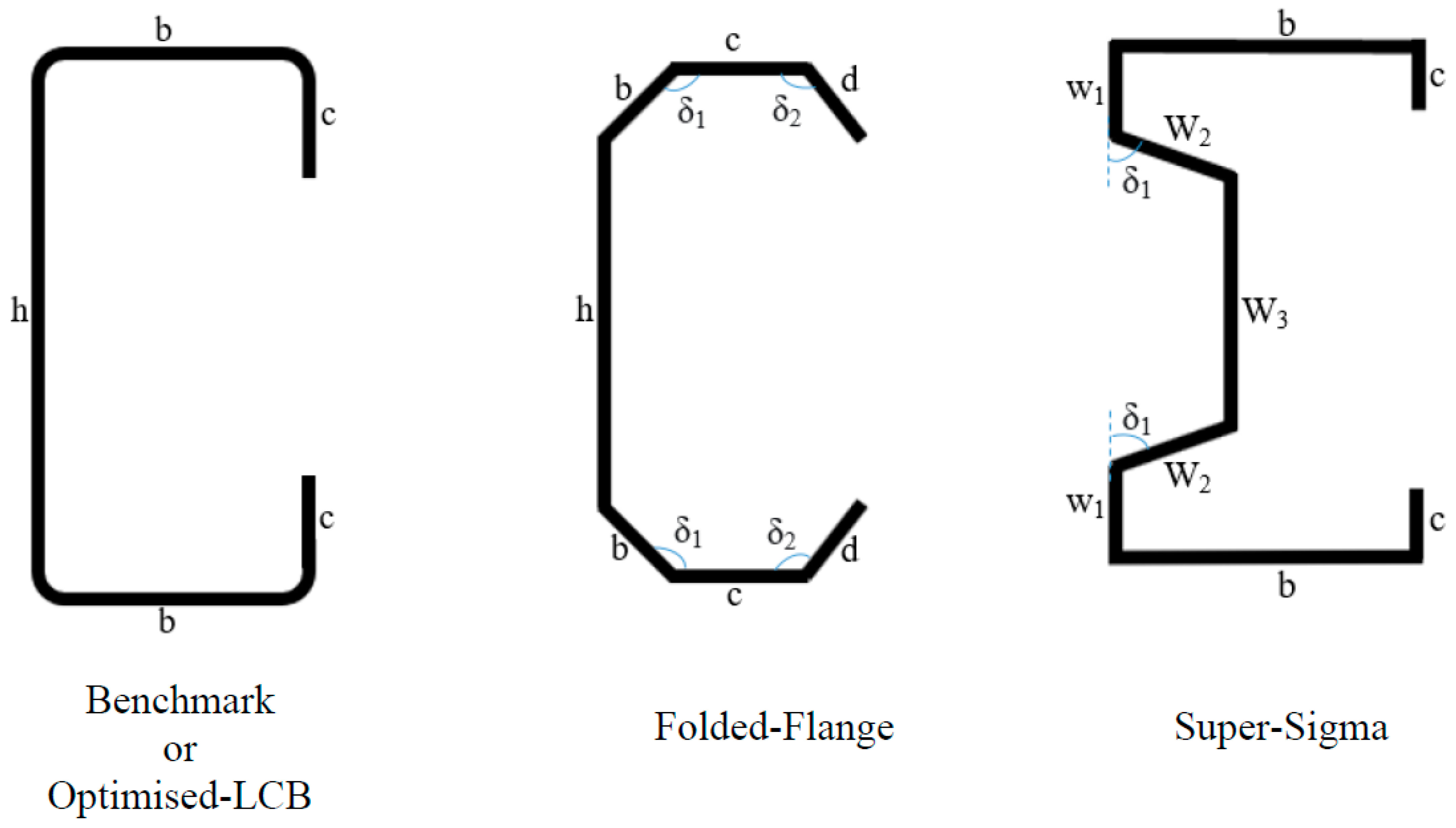
| Benchmark or Optimised-LCB |  |  |
| Folded-Flange | 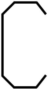 | 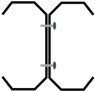 |
| Super-Sigma | 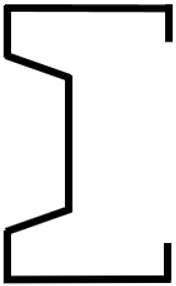 |  |
| Material | Material Strength (MPa) | Density (Kg/m3) | Young’s Modulus (MPa) | Poisson’s Ratio |
|---|---|---|---|---|
| CF carbon steel | fy = 220 | 7850 | 210,000 | 0.30 |
| fy = 450 | ||||
| CF aluminium | 5052-H14 (fy = 180, fu = 230) | 2700 | 70,000 | 0.33 |
| 3004-H48 (fy = 220, fu = 260) | ||||
| CF stainless-steel | 1.4307 (fy = 220, fu = 520) | 7850 | 210,000 | 0.30 |
| 1.4362 (fy = 450, fu = 650) |
| No. | Specimen | Reference | Test | Failure Mode Observed in Experimental | FE | Failure Mode Observed in Numerical | MExp/MFE |
|---|---|---|---|---|---|---|---|
| MExp (kNm) | MFE (kNm) | ||||||
| 1 | OT0.42-86-S75 | [13] | 1.206 | D + L | 1.294 | D + L | 0.93 |
| 2 | OT0.42-86-S300 | 1.222 | D + L | 1.321 | D + L | 0.93 | |
| 3 | OT1.2-86-S75 | 7.417 | D + L | 7.230 | D + L | 1.03 | |
| 4 | OT1.2-86-S75R1 | 7.303 | D + L | 7.062 | D + L | 1.03 | |
| 5 | OT1.2-86-S75R1-R | 7.341 | D + L | 7.012 | D + L | 1.05 | |
| 6 | OT1.2-86-S300 | 7.030 | D + L | 7.366 | D + L | 0.95 | |
| 7 | OT1.2-136-S150 | 12.240 | D + L | 12.378 | D + L | 0.99 | |
| 8 | OV-0.48-B4 | [1,2] | 1.246 | L + F | 1.335 | L + F | 0.93 |
| 9 | OV-1.0-B4 | 4.238 | L + F | 4.385 | L + F | 0.97 | |
| 10 | OI-0.48-B4 | 1.880 | L + F | 2.088 | L + F | 0.90 | |
| 11 | OI-1.0-B4 | 6.092 | D + F | 6.180 | D + F | 0.99 | |
| 12 | OI-1.2-B4 | 7.208 | D + F | 8.018 | D + F | 0.90 | |
| Mean | 0.97 | ||||||
| COV | 0.05 | ||||||
| Section Types | Sections | Materials | Material Classifications |
|---|---|---|---|
| Single | LCB-benchmark, Optimised-LCB, Super-Sigma, Folded-Flange | CFS | fy = 220 MPa fy = 450 MPa |
| CF aluminium | H14 H48 | ||
| CF stainless steel | 1.4307 1.4367 | ||
| Built-up | LCB-benchmark, Optimised-LCB, Super-Sigma, Folded-Flange | CFS | fy = 220 MPa fy = 450 MPa |
| CF aluminium | H14 H48 | ||
| CF stainless steel | 1.4307 1.4367 |
| Parameters | h (mm) | b (mm) | c (mm) | d (mm) | W1 (mm) | W2 (mm) | W3 (mm) | δ1 (°) | δ2 (°) | |
|---|---|---|---|---|---|---|---|---|---|---|
| Sections | ||||||||||
| Benchmark | 231 | 75 | 17 | - | - | - | - | - | - | |
| Optimised-LCB | 269 | 50 | 23 | - | - | - | - | - | - | |
| Folded-Flange | 185 | 48 | 50 | 17 | - | - | - | 105 | 95 | |
| Super-Sigma | 270 | 50 | 17.5 | - | 41 | 30 | 139 | 34 | - | |
| Material | CFS | AL | SS | |||
|---|---|---|---|---|---|---|
| Sections | fy = 220 MPa | fy = 450 MPa | H14 | H48 | 1.4307 | 1.4362 |
| Benchmark | 16.05 | 24.60 | 6.30 | 7.35 | 16.05 | 25.50 |
| Optimised-LCB | 16.55 | 29.10 | 7.80 | 8.55 | 16.65 | 32.40 |
| Folded-Flange | 18.45 | 39.45 | 12.90 | 15.75 | 21.00 | 43.35 |
| Super-Sigma | 13.50 | *NA | 8.70 | 11.25 | 16.80 | 34.50 |
| Material | CFS | AL | SS | |||
|---|---|---|---|---|---|---|
| Sections | fy = 220 MPa | fy = 450 MPa | H14 | H48 | 1.4307 | 1.4362 |
| Benchmark | 5.40 | 10.41 | 2.10 | 2.55 | 6.00 | 12.45 |
| Optimised-LCB | 7.35 | 13.28 | 3.00 | 3.60 | 7.65 | 14.85 |
| Folded-Flange | 7.80 | 16.60 | 3.90 | 4.65 | 8.70 | 18.75 |
| Super-Sigma | 6.30 | 14.90 | 2.70 | 3.45 | 7.35 | 15.45 |
Publisher’s Note: MDPI stays neutral with regard to jurisdictional claims in published maps and institutional affiliations. |
© 2022 by the authors. Licensee MDPI, Basel, Switzerland. This article is an open access article distributed under the terms and conditions of the Creative Commons Attribution (CC BY) license (https://creativecommons.org/licenses/by/4.0/).
Share and Cite
Kanthasamy, E.; Hussain, J.; Thirunavukkarasu, K.; Poologanathan, K.; Roy, K.; Beulah Gnana Ananthi, G.; Suntharalingam, T. Flexural Behaviour of Built-Up Beams Made of Optimised Sections. Buildings 2022, 12, 1868. https://doi.org/10.3390/buildings12111868
Kanthasamy E, Hussain J, Thirunavukkarasu K, Poologanathan K, Roy K, Beulah Gnana Ananthi G, Suntharalingam T. Flexural Behaviour of Built-Up Beams Made of Optimised Sections. Buildings. 2022; 12(11):1868. https://doi.org/10.3390/buildings12111868
Chicago/Turabian StyleKanthasamy, Elilarasi, Janaid Hussain, Kajaharan Thirunavukkarasu, Keerthan Poologanathan, Krishanu Roy, G. Beulah Gnana Ananthi, and Thadshajini Suntharalingam. 2022. "Flexural Behaviour of Built-Up Beams Made of Optimised Sections" Buildings 12, no. 11: 1868. https://doi.org/10.3390/buildings12111868