Abstract
In the construction project, the temporary work is the construction work, which is installed temporarily for the construction of main structure and removed after its completion. Even though it is a temporary facility used and demolished only during the construction phase, it accounts for about 10% of the total construction cost. In addition, it is an important work directly connected to the cost and quality of construction, so that the completeness of the building depends on the technology of the temporary work. Therefore, it is necessary to manage it through systematic quality inspection activities. In order to perform a systematic quality inspection, it is essential that detailed and specific inspection activities, such as inspecting the conformity of the design and construction and its compliance with relevant standards based on construction inspection information, such as drawings, specifications, and checklists, are carried out. However, most of the construction inspection information about the temporary work does not include any specific information in documents (drawings, specifications, etc.). Additionally, the direct temporary work among the temporary works is treated as an auxiliary work of the main structure work in the construction site, although it is the construction work based on the work breakdown structure. Accordingly, the quality control engineer must manually check only the contents of the temporary work among the construction inspection information that covers the overall construction work. Additionally, the probability of human error is increased, as the quality control engineer manually carries out the quality inspection tasks, such as preparing the inspection-related materials and checklist and writing the inspection result report. This leads to inefficiency and problems such as re-provisioning for inspection and re-inspection. Therefore, it is necessary to construct a business process that can efficiently carry out the quality inspection work by complementing and improving the above problems involving the temporary work, which is performed most inefficiently. In this study, a BIM-based quality inspection system prototype for temporary works was developed that can automate tasks and systematically store and manage various types of inspection information for each of the temporary facilities in order to improve the efficiency of the quality inspection carried out by the quality control engineer. As a result, a process designed to improve the quality inspection of the temporary work, which can perform the quality inspection work, is proposed. Additionally, the quality of the works related to quality control is improved through improvements in the accuracy and efficiency of the works and simplification of the existing manual work procedures through the proposed business improvement process.
1. Introduction
An article that was published in Korea Land Daily on 14 February 2017 (temporary construction accidents at construction sites 100% attributable to poorly implemented installation) states that the main cause of accidents in temporary construction, which account for most of the accidents that occur on construction sites, is poorly executed temporary construction rather than defective materials. This article, which is based on an analysis that was conducted by the Ministry of Land, Infrastructure, and Transport (MOLIT), suggests that the occurrence of accidents on construction sites is dependent on the quality of the temporary construction. Consequently, in Article 54 of the Quality Management Practice Guidelines for construction works, the Ministry stipulates that the quality of temporary structures should be inspected to prevent poor construction.
Temporary construction tends to be more dependent on experience compared with other construction processes, because temporary structures are often not included in the blueprints. It is difficult to inspect the quality of temporary structures because their construction is based on the type of construction work and the form of the shop drawing. Therefore, when a quality management engineer (QM engineer) inspects a temporary construction structure, the engineer has to inspect it based on information (general standards) that is not included in the blueprints. Thus, temporary construction is inefficient compared with other construction processes.
Furthermore, although the direct temporary work, which is a type of temporary construction work, is considered a sub-construction process of the main structures, the work breakdown structure considers it to be a construction process [1]. Owing to this, information on the general standards that are required to inspect temporary structures is disorganized. Consequently, the contents that address the temporary construction, such as the construction specifications, design drawings, and construction work plan, are manually extracted. The inspection of temporary structures entails repetitive work, and the extracted contents have to be organized according to their respective subjects. Additionally, in most cases, QM engineers have to review the government standards, because temporary construction works are often not included in the design drawings and documents. However, because the information on the general standards that regulate temporary construction works are scattered across the standards of various government agencies, such as the Korean construction specification (KCS), Construction Technology Promotion Act of MOLIT, Occupational Safety and Health Act of the Ministry of Employment and Labor, and Construction Waste Recycling Promotion Act, it is difficult to inspect all the required information.
Consequently, to enhance the performance of temporary construction structures, a quality inspection process for temporary construction works should be developed. To this end, the Korean construction standard (KCS) is investigated, and the current quality inspection work is analyzed. Based on this, the primary expected problems that may occur at each stage of the work are derived, which we verified by conducting questionnaires and interview surveys. Then, in this study, a BIM-based temporary construction quality inspection work process model and system prototype was developed to improve these problems.
In the field, although various efforts to secure the quality of the construction project were performed for major works, the effort was relatively insufficient for temporary works. Field workers recognize that improvement is necessary for temporary construction, and in terms of policy, the obligation to secure the stability and quality of temporary construction is increasing. Therefore, this study can be regarded as a very meaningful study in the same trend.
Academically, most of the previous studies have been conducted on main structures or formwork [2,3,4,5,6,7,8,9,10,11,12,13]. Therefore, research on temporary construction or temporary facilities is highly insufficient, and it is necessary to actively conduct studies. Among them, this study, conducted as part of quality assurance efforts for temporary construction, is considered to be useful, as it provides practical data for temporary construction in the future.
2. Temporary Construction Works and Quality Inspection
2.1. Temporary Construction Works
Temporary construction work (TCW) is defined as “conducting the inspection, measurement, and preparation works for the framework of standards as well as constructing or demolishing structures, including site offices, warehouses, roads earmarked for construction, power facilities, plants, motor pool, water supplies or drainage facilities, safety facilities, and temporary structures, that are supposed to be demolished after the completion of the intended construction work” [14]. TCWs are grouped into two categories. The first category is common temporary construction (e.g., temporary buildings, temporary fences, and temporary roads), and the second is direct temporary construction (e.g., scaffolds, molds, cast iron, and footing boards). The former (common temporary construction) facilitates construction comprehensively and indirectly, whereas the latter (direct temporary construction) enables a specific construction process [15].
The items that are related to the technical standards of TCWs are stipulated in the Korean construction standard code of the MOLIT. The Korean construction standard codes were enacted in 2016 to facilitate the efficient management of construction standards and mitigate the issues that limit the effectiveness of the classification standards for construction specifications, as well as the standardized specifications for TCWs, such as incompatibility, redundancy, and inconsistency. The Korean construction standard codes promote the achievement of the aforementioned objectives by integrating the two categories of standards and creating a harmonized standard. The construction standard code that was developed by MOLIT is divided into two parts, namely the Korean design standard code (KDS) and the Korean construction standard (KCS), and each of the standards refers to common information, facilities, and project categories. Temporary facilities utilize KDS 21 00 00 for the design code and KCS 21 00 00 for the specification code.
The specification items of TCWs are listed in the facilities sector of the KCS. They are managed as standardized specification codes for TCWs, as illustrated in Table 1. The standardized specification code for TCWs consists of 8 categories and 15 sub-categories, and it is denoted by code “21 00 00”, TCW. In this study, 72 facilities, which are classified by the KCS, are considered. In addition, by classifying TCWs into sub-categories according to their general contents, materials, and works, KCS offers a general standard. Therefore, this study uses the Korean construction standard specification code (KCS) for TCW as a categorizing standard for temporary construction structures, which must be inspected on every construction site. The scope of this research is limited to movable scaffoldings, and these movable scaffoldings are utilized in temporary facilities that exclude special facilities, which require structural reviews. The movable scaffoldings are widely used on most construction sites, and they can be moved and utilized intermittently. Furthermore, due to their high frequency of use and high accident rate, scaffoldings require systematic field inspections [16].

Table 1.
TCW categorization system of Korean construction standard specification code (KCS).
2.2. Quality Inspection
2.2.1. Definition of Quality Inspection
Quality can be defined as “the requirement that a given product should meet its required performance”. In other words, products must satisfy their users’ satisfaction level with respect to their requirements and suitability for use [17]. Article 2 of the MOLIT (Quality Management Practice Guidelines for construction works) defines quality management as the inspection activities that are performed to ensure that the quality of a structure is in conformance with the applicable codes and standards, as well as the design drawings and documents. The scope of the work includes not only inspecting the status of the installations and testing the materials that are used in construction but also preventing the execution of tasks that do not conform with the design drawings and construction documents.
In construction works, quality inspection includes regular inspections, joint inspections, field inspections, and adequacy inspections. In general, the inspection methodology depends on the purpose and characteristics of the construction [17]. An initial inspection is conducted by the QM engineers after the completion of the construction work. The systematic and effective inspection activities of this initial inspection can prevent administrative measures, such as correction orders and local corrections, and it can also provide necessary caution by decreasing the errors that are reported in the quality inspections conducted by the ordering entity and inspection agency. Therefore, this research focuses on the quality inspection activities that QM engineers perform while conducting quality inspections.
2.2.2. Analysis of the Current Quality Inspection Process for TCWs
In the Korean construction field, QM engineers are expected to inspect the construction status of every work stage for both temporary and permanent facilities. By inspecting the construction status of every work stage, quality inspections decrease the number of reported errors. Figure 1 illustrates that the quality inspection process that a QM engineer performs consists of three stages: pre-inspection, inspection, and post-inspection. Quality inspection results are to be submitted to the construction project manager in writing, and they should be accompanied by an inspection request document.
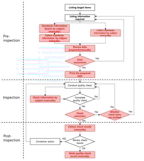
Figure 1.
Current TCW quality inspection work process.
In the pre-inspection stage, the QM engineer prepares the data that are required for the quality inspection to be performed. This stage normally includes works such as preparing drawings and standards, as well as extracting or reviewing the checklist. However, unlike main construction works, TCWs are rarely included in the design drawings; therefore, construction plans and specifications are often utilized in the inspection of TCWs. To prepare for an inspection of TCWs, the QM engineer should create a list of the subjects of the inspection and the main items that need to be inspected for each subject. In addition, the QM engineer should search for the information that needs to be referenced during the inspection, including construction drawings and documents (e.g., construction specifications and contract documents), standard specifications, and the laws of each government department. In the pre-inspection stage, all the work is performed manually. However, this method is problematic. The manual work that is performed during the pre-inspection stage increases the probability of human error, which is characterized by error occurrences, such as the omission of checklist items or the omission of measurement information. Thus, the reliability of the inspection data is decreased. Additionally, the work may be repeated, and this may cause the quality inspection work to be delayed. In this chapter, diversity and scope, which are factors that influence the quality inspection work for TCWs, are discussed. For QM engineers to manually inspect TCWs, they must utilize their working hours inefficiently.
In the inspection stage, the inspection is performed based on the inspection data, such as checklists and relevant standard information that were collected in the pre-inspection stage. In this stage, the QM engineer compares the actual construction status of temporary facilities with the measured information. Subsequently, the QM engineer records the information on a prepared checklist. Because there are many scenarios where TCWs lack design drawings, the inspection stage should rely on the relevant standard information. Therefore, to facilitate the effective quality inspection, the measurement information that pertains to a particular TCW should be handed over on the site. However, because most inspection preparation data that are created in the pre-inspection stage are print-based, it is difficult to inspect them immediately owing to their poor portability. Additionally, it is difficult to correct writing errors that appear in inspection preparation data because the inspection items are supposed to be written on the checklist. The unreliability of the inspection preparation data that are created during the pre-inspection stage affects the inspection stage. There may be cases where the inspection preparation data are insufficient or scenarios where the work must be repeated once an error has occurred and is identified.
On the other hand, there are several scenarios where inspections are conducted without the identification of errors in the inspection data. Therefore, in most cases, the inspection cannot be performed on the basis of precise information, and this renders the inspection highly dependent on the QM engineer’s experience. Because the inspection preparation work is performed manually, the potential problems that are experienced in the pre-inspection stage can affect the inspection stage. Thus, inspection work can be a formal but meaningless activity, because the potential problems that are created in the pre-inspection phase can decrease the effectiveness of the quality inspection. Consequently, the researchers developed the following resolution: quality inspection works should be conducted systematically because their benefits, which include the prevention of poor construction and quality assurance, may be undermined by the potential problems.
The post-inspection stage, which is the last stage, allows QM engineers to take corrective action by enabling them to synthesize and assess the inspection results. In this stage, the QM engineer, who is stationed on-site, re-inputs the checklist for each temporary facility to determine whether the assessment result is a pass or fail. If the assessment result is “pass”, the QM engineer requests an inspection that has a checklist and the review data attached by submitting a written inspection request form to the construction project manager. If the result is “fail”, self-corrective actions are taken regarding the construction status of the temporary facility, and a re-inspection is conducted. The following problem can arise during the post-inspection stage: re-putting the output of the checklist that was manually created during the inspection stage, which can lower the efficiency of the inspection by increasing the work time, redundancy in work processes, and input errors. Additionally, in the post-inspection stage, “fail” results, which are determined during the quality inspection, may lead to additional work, such as processing the documented errors and taking corrective actions. Thus, a precise and quick method of dealing with “fail” results is required.
2.2.3. Analysis of Practical Problems in Quality Inspection of TCW
To solve the practical problems that affect the quality inspection of TCWs, numerous surveys and interviews were conducted. The current quality inspection work processes for TCWs were analyzed to clarify the problems related to the quality inspection of TCWs. Both a survey and an interview were conducted. The participants of the survey and interview were 27 QM engineers with varying levels of experience, namely novice, intermediate, advanced, and expert, and the QM engineers had an average experience of 4.8 years in apartment construction projects. The survey enabled the researchers to compare the inspection information that is gathered for temporary facilities with the inspection information that is collected for permanent structures, and it also allowed them to determine the manner in which the standards of quality inspection for temporary facilities are reviewed. In addition, the manner in which QM engineers design quality inspections checklists that are created for temporary structures was observed. The determination of the most time-consuming works in the pre-inspection stage is a critical issue. In the inspection stage, QM engineers are mainly concerned with the portability of the standards, the difficulties associated with carrying print-based standards, and the manner or difficulty of documenting the quality inspection results. In the post-inspection stage, the QM engineer develops a strategy to solve the problems that were identified during the inspection stage by reviewing the documentation on the results and suggesting ideas that can improve the work process.
Using surveys and interviews, the problems related to quality inspections of TCWs were clarified. As shown in Table 2, they are divided into two categories: error occurrences in works and inefficiency problems.
Table 2.
Problems in QM engineers’ inspection work for TCWs.
3. Design of a BIM-Based TCW Quality Inspection System
3.1. Efficient Inspection Process
To model the TCW quality inspection works, it is necessary to organize the unit works in the existing work process. Furthermore, the unit works that have inherent problems should be substituted with alternative unit works. The modeling can only be made possible by collecting new unit works. If the new unit works are collected, newly created data should be defined, and the workflow should be determined. Therefore, this research establishes unit works based on the result of an analysis of previous quality inspections. The research also establishes an improved TCW quality inspection work process that can mitigate the problems experienced in existing TCW quality inspection works.
Unit work is the lowest unit, and it is normally defined as an input process and output process. When the unit work is performed, a complete and meaningful result should follow. To organize the unit works, existing works should be broken down into unit works, and unit works that could potentially impede quality inspections should be established. In addition, the new unit works should be established by changing and deleting the problematic unit works to enhance the development [18]. Hence, the research breaks down the current TCW quality inspection works into unit works, as illustrated in Table 3 [15,19,20,21,22,23]. The problematic unit works, which can occur when QM engineers conduct quality inspection works, were established through a preceding research analysis and consultations with professionals. Alternative works for the problematic unit works were suggested through prescribed actions, such as changes, deletions, subdivisions, and integrations, as well as the development of a system using BIM and a database.
Table 3.
Organization of TCW quality inspection unit works.
The target items are categorized into the BIM library selection, for temporary facilities, and BIM modeling work, for alternative unit works. This categorization prevents the omission of targeted items that occurs during the process of listing them manually based on design drawings and documents. The inspection target items are listed with respect to the BIM model. BIM modeling facilitates the simplified and quick assessment of size and quantity information by allowing QM engineers to place temporary facilities on three-dimensional BIM drawings when the BIM library is selected. In addition, the search, collection, and documentation of standards that were manually prepared are integrated through automated extraction and the creation of a checklist. Furthermore, the review of the inspection data that were manually prepared is also automated. These changes prevent the potential errors that might occur as a result of manual work. The portability and accessibility of the required information (standards) are enhanced by digitalized inspection data, which can be transferred to mobile devices. The documentation of the inspection results, which was previously manual, is now automated; thus, the work efficiency is increased. The unit works that are illustrated in Figure 2 are intended to act as the basis of the proposed TCW quality inspection work process. Moreover, the data drawn from each detailed work stage and the flow of information are organized based on this quality inspection work process.
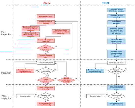
Figure 2.
Comparison of TCW quality inspection unit works (AS-IS vs. TO-BE).
3.2. System Prototype Configuration
The system prototype consists of three modules: the BIM modeling module, the temporary facilities quantity inspection module, and the temporary facilities quality inspection module. The BIM modeling module is designed to model each temporary facility in the pre-inspection stage. Instead of modeling temporary facilities themselves, the users can utilize the BIM library and place the temporary facility on the BIM drawing. Furthermore, by utilizing the temporary facilities BIM, the temporary facilities quantity inspection module facilitates the automatic inspection of the quantity, which is the target item of a TCW inspection. Finally, the temporary facilities quality inspection module is a module that conducts each work in the post-inspection stage.
3.2.1. Required Function Definition
To develop a system prototype, the required functions of the system prototype should be defined. Therefore, based on the aforementioned alternative unit works, problems that can be systemically resolved were observed among the problems from the existing quality inspection work, as illustrated in Table 4. The function requirements are drawn from the new unit works, and the quality inspection work can be improved by developing the details of each required function and factoring them into the system prototype.
Table 4.
System prototype function requirements.
The work of the automation function, which is one of the required functions, aims to prevent human error in the pre-inspection stage. The system prototype should enable the automatic extraction of the standards related to each inspection subject, and it should also facilitate the automatic creation of the checklist. In addition, in the inspection stage, print-based activities should be converted to system-based activities. The sharing of information through mobile devices increases the portability and usability of the required inspection data. Furthermore, in the post-inspection stage, the quality inspection assessment of the shared inspection result should be conducted automatically through the system prototype. Thus, the development should achieve the automated extraction and creation of inspection request forms, quality inspection reports, and disqualified items. Subsequently, the functions that are required to enhance the usability of the required inspection data include the inputting and offering of the information that is required by the inspection subject in the system prototype. These functions can shorten the work time that is required for the preparation of the quality inspection, which is conducted during the pre-inspection stage. In addition, QM engineers do not have to determine anything using their own experience, because they can promptly check the required information in the inspection stage. Furthermore, QM engineers can review the inspection history using the inspection records, which are collected on-site by a mobile device, and this can lead to the better management of the inspection subject.
3.2.2. System Prototype Logic
The logic of the proposed system prototype for TCW quality inspection is depicted in Figure 3. First, the temporary facilities module calls the temporary facilities library by selecting the condition that corresponds to the category and sub-category based on the construction standard code described above. Once it calls the library, the standards, which must be referenced to enable the design of the temporary facilities to commence, are automatically suggested. This process facilitates the error minimization and BIM modeling. Furthermore, it determines the types of temporary facilities and their conformity with the standards, and it completes the modeling if there are no disqualified items. Once the modeling is completed, the attribute information is extracted from the temporary facilities BIM model based on the BIM library. Subsequently, the quantity information follows, and it is called by the BIM module. Quantity information, which is among the attribute information that is included in the BIM model, is extracted, and the quantity of each temporary facility is automatically calculated to facilitate the quantity inspection for the targeted temporary facilities. Moreover, to achieve a quality inspection, the attribute information is extracted from the temporary facilities BIM model in the form of a quantity inspection, and the quality inspection module calls that information. The system prototype allows the data to be extracted from the standards database or the inspection items database for the checklist’s creation based on the information that is called, and this leads to the automated creation of checklists. In addition, once the inspection result information has been created, the final inspection result report can be automatically created.
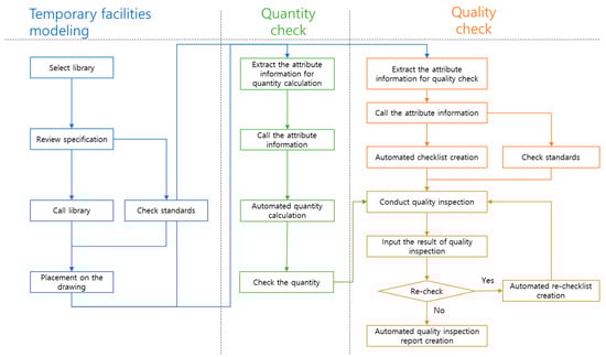
Figure 3.
System prototype logic diagram.
4. BIM-based TCW Quality Inspection System Prototype
4.1. BIM Modeling Module
The BIM modeling module of the prototype is illustrated in Figure 4. Each circled number indicates the following steps: ① select the items through the section or category of the library’s classification system prototype and select the sizes through the detailed category; ② press the enter button; ③ preview; ④ call the library; and ⑤ automatically create relevant standards according to the previous actions. To proceed with the modeling, check the relevant standards by clicking ⑤, which is the relevant standards button. Figure 5 illustrates the process flowchart of the BIM modeling module.
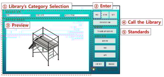
Figure 4.
BIM modeling module.
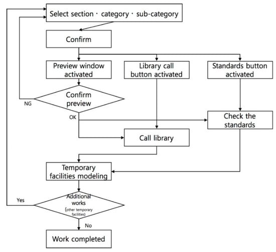
Figure 5.
Process flowchart—BIM modeling module.
The details pertaining to each function of the BIM modeling module that is utilized in the system prototype are as follows. First, in terms of the library selection, selecting the initial library category creates a category list according to the selected section. For the appropriate library to be selected, the detailed category is created based on the category that is selected. Figure 6 illustrates an example. If a movable scaffolding that has a height of 2 m destined to be used for a 3-month period is modeled, “Scaffoldings”, which is located in the section that has options such as “Casting iron”, “Scaffoldings”, “Falling disaster prevention facilities”, and “Falling object disaster prevention facilities”, should be selected. Subsequently, “Movable scaffoldings”, which is situated in the category that has options such as “Steel pipe scaffoldings”, “Steel pipe frame scaffoldings”, “System scaffoldings”, and “Movable scaffoldings”, should be selected. Finally, “Height 2 m (3 months)”, which is the size and period of use in the detailed category, should be selected. Thus, a three-dimensional BIM model of a movable scaffolding that has the aforementioned attribute information can be selected, and the standards related to the movable scaffolding can be reviewed.
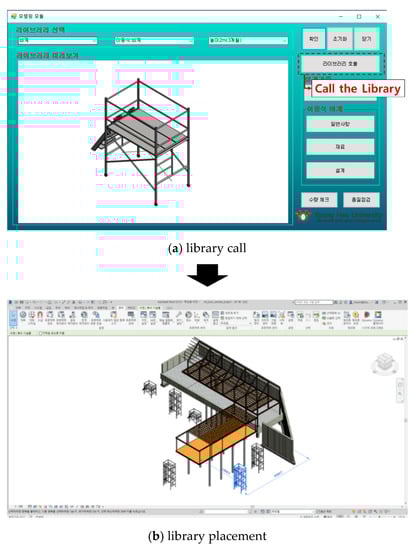
Figure 6.
BIM modeling module—library call.
Once the selected library is called, the window and button that provide each type of attribute information, such as the preview and standards, are activated. Thus, the three-dimensional BIM model will be displayed, and the related library and standards will be called simultaneously. As depicted in Figure 7, the library of the movable scaffoldings, which can be selected from the temporary facilities library database, is matched so that it can be called on by the Revit BIM drawing. Subsequently, a three-dimensional BIM model for the movable scaffolding is completed by simply placing the called BIM model of the movable scaffoldings on the BIM drawing. In this scenario, the temporary facilities library can be applied to the BIM drawing by opening the library file using Revit and naming the library as (a) and using the function “Place it on the project”, naming it as (b).
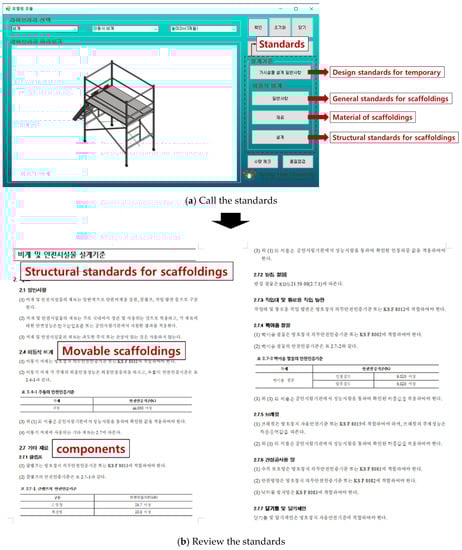
Figure 7.
BIM modeling module—check the standards.
The BIM modeling can proceed by checking the temporary facilities design common items, which can be automatically matched through the standards database. For example, as shown in Figure 7a, once a movable scaffolding is selected, only the standards that are specific to the movable scaffolding, such as the materials and design, can be called from the database. The standards that are required to review the movable scaffolding standards are retrieved, as illustrated in Figure 7b.
4.2. Quantity Inspection Module
For the temporary facilities quantity inspection, the name, size, and quantity, which are the types of attribute information that are required for the quantity inspection, can be automatically extracted and converted to an Excel file using Revit’s Dynamo, as illustrated in Figure 8. Dynamo, which is installed during the installation of Revit, is the graphic programing interface with which the building information workflow can be customized. Using Dynamo, the BIM workflow can be simplified and automated. From the management menu (①) of Figure 8, both Dynamo Player (②), which is situated in the management tab of Revit, and the module (③) are executed to automatically save the relevant attribute information, which is required for the quantity inspection, to an Excel file.
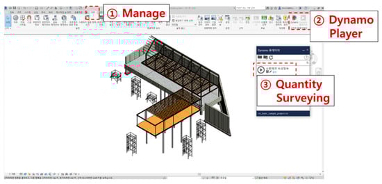
Figure 8.
Automatic extraction of the attribute information for the temporary facilities quantity inspection using Dynamo.
The calculation rule of Dynamo (Figure 8) is illustrated in Figure 9. To model a “Movable scaffolding”, Dynamo checks the size of the initially modeled movable scaffolding. Subsequently, to calculate each quantity, it categorizes the moveable scaffolding into two different attributes. The first attribute, “size”, is classified as “Height 2 m” and “Height 4 m”, and the second attribute, “period of use”, is classified as “3 months”, “6 months”, and “12 months”.
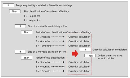
Figure 9.
Temporary facilities quantity inspection module—dynamo calculation rule.
Once the quantity information is saved by Dynamo, the new button (①) from the quantity inspection module, which is illustrated in Figure 10, is utilized to activate the dialogue window that allows the user to select files. Subsequently, the Excel file (②) is selected (③) to retrieve and check the information pertaining to the size and quantity of the movable scaffolding.
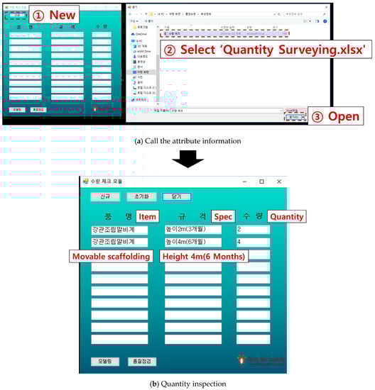
Figure 10.
Calling the attribute information that pertains to the temporary facilities quantity and checking the quantity.
The process flowchart that pertains to the temporary facilities quantity inspection, which is described above, is illustrated in Figure 11.
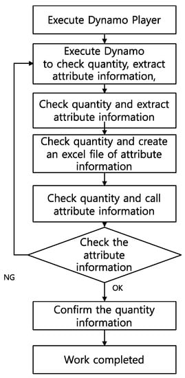
Figure 11.
Process flowchart—temporary facilities quantity inspection module.
4.3. Quality Inspection Module
Figure 12 illustrates the temporary facilities quality inspection module. Once the modeling of the movable scaffolding, which is placed on the BIM drawing, is completed, the user can save the attribute information pertaining to the movable scaffolding, which is modeled through Dynamo, to an Excel file so that it can be called in the system prototype. The system prototype recognizes the attribute information pertaining to the movable scaffolding from the Excel file that is called, and it automatically creates the checklist. If the check result, such as “Re-look” or “Fail”, is input, a re-inspection list is automatically created. Subsequently, if corrective action and re-inspection results are input, the system prototype confirms whether the re-inspection is completed. If the re-inspection is completed, the system prototype automatically creates the quality inspection result report. For the quality inspection, which is the same as the quantity inspection, the Revit management tab (①) that is depicted in Figure 12 is utilized to execute Dynamo Player (②), and the module (③) is executed to automatically save the attribute information to an Excel file.
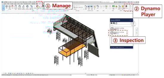
Figure 12.
Automatic extraction of the attribute information pertaining to temporary facilities for the quality inspection using Dynamo.
Once the quality inspection information is saved to an Excel file using Dynamo, the Checklist button (①), which is depicted in Figure 13, is pressed. Consequently, the dialogue and select window files are activated. To retrieve the attribute information pertaining to the movable scaffoldings from the quality inspection module, the Excel file (②) is opened (③), and the quality inspection checklist for the movable scaffolding is automatically created.
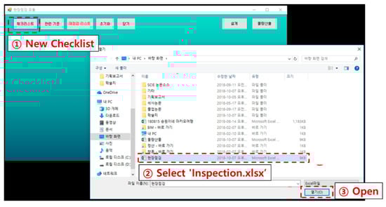
Figure 13.
Quality inspection module—automated creation of the checklist.
Subsequently, using the quality inspection checklist for the movable scaffolding, the quality inspection can be conducted. The result of the quality inspection can be input into the quality inspection module, as illustrated in Figure 14. A decision, such as Pass, Re-look, or Fail, can be input in ①, while for re-look or the failed items, the corrective action pertaining to the movable scaffolding should be input in ②. If there are any re-inspection items from the inspection result, in order to automatically create the re-inspection list, the re-inspection list button (③) needs to be pressed, as illustrated in Figure 15.
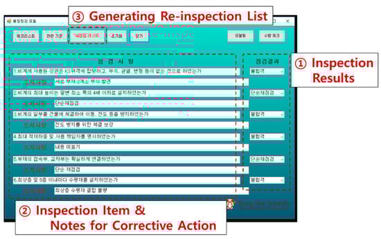
Figure 14.
Quality inspection module—quality inspection result input.
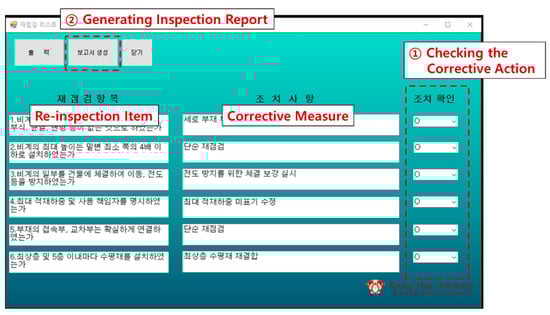
Figure 15.
Quality inspection module—automated creation of the checklist.
After conducting a re-inspection and checking the corrective action for the movable scaffoldings, a quality inspection checklist (①) and a quality inspection result report (②) will be automatically produced, as illustrated in Figure 16 and Figure 17, respectively.
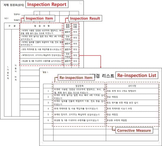
Figure 16.
Quality inspection module—quality inspection report creation.
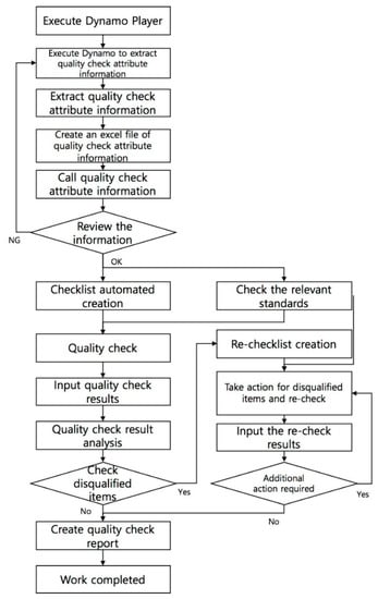
Figure 17.
Process flowchart—temporary facilities quality inspection module.
5. Performance Evaluation of BIM-Based TCW Quality Inspection Work
5.1. Case Project and Performance Measures
A case project is utilized to compare the two methods in terms of their performance. The basic information of the case project is as illustrated in Table 5.
Table 5.
Case project overview.
5.2. Performance Evaluation Method and Process
To compare the improved TCW quality inspection work process with the case project, both the existing work process and the improved work process were analyzed, respectively, as illustrated in Figure 18.
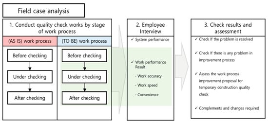
Figure 18.
Evaluation process using a sample project.
The performance results of the two work processes were derived by conducting actual quality inspection works using the work processes. Furthermore, the improvements in terms of accuracy, time, and convenience were compared and analyzed through an interview with the individual who utilized the improved work process. The researchers measured the accuracy, time, and convenience of the improved work process to evaluate its performance. To determine the accuracy of the work, omissions in the inspection subjects and items in the checklist, omissions in the standards, the extraction of unnecessary standards, omissions in the modeling, and errors in the inspection result collection and reports were recorded and compared with the actual construction site data. Subsequently, the researchers determined whether the results of the works were sufficient to assess the accuracy. To evaluate the improvements in the time required for the quality inspection, the amount of time consumed was measured and recorded. To assess the extent to which the convenience of the quality inspection work process could be enhanced, a survey and interviews were conducted.
5.3. Evaluation Results of Inspection Works
The first evaluation was conducted with three construction experts with over 10 years of experience in construction but without any experience using BIM for construction works. On the other hand, the second evaluation was conducted with 28 students, who were enrolled in either an undergraduate or a graduate degree program.
5.3.1. Work Accuracy Assessment
To assess the work accuracy, the same works were executed three times. Because the result of the work determined its accuracy, the number of people in the evaluation group who accurately utilized the improved work process was compared using the following expression:
Here, A denotes the number of people who utilized the improved work process accurately, B denotes the number of people who utilized the existing work process accurately, and C denotes the number of people who participated in the evaluation.
Table 6 indicates that the accuracy of the overall performance result improved. When the pre-inspection works that followed the improved (R-QIST) work process were compared with the works that followed the existing work process, the researchers observed that the performance result improved by 66.7% in the first evaluation and by 58.3% in the second evaluation. On the other hand, when the post-inspection works that were performed using the newly developed system prototype were compared with the post-inspection works that were conducted using the existing work process, the researchers observed that the performance result improved by 55.6% in the first evaluation and by 65.5% in the second evaluation.
Table 6.
Work accuracy measurement results from each work process.
In the existing work process, there were omissions in the inspection subjects or the items of the quality inspection checklist and the required standards or the extraction of unnecessary standards. Consequently, the performance results were inaccurate, and these inaccuracies were represented by omissions in the collection of the inspection results and errors in the written reports. However, with the improved work process, all the performance results of the works were accurate.
5.3.2. Work Time Measurement
Pre-Inspection Stage
During the measurement of the time taken to conduct the pre-inspection works in the first evaluation, the search for the inspection information that pertained to the quality inspection work had to be performed only in regard to the standards that refer to the movable scaffolding, which appear in the list “2.3.3 TCW quality-inspection-work-related inspection”, and the inspector had to prepare a checklist. As in the case of the first evaluation, the standards information and checklist were necessary for the second evaluation, which was performed under the same conditions as the first evaluation. Using the result of the quality inspection work that was performed in the pre-inspection stage, the developed system prototype was compared with the existing work process, and the researchers observed the following results. With respect to the standards information creation stage, the work time decreased by 98.7% and 98.0% in the first evaluation and second evaluation, respectively as illustrated in Table 7 and Table 8. In addition, in the checklist creation stage, the work time decreased by 86.5% and 88.0% in the first evaluation and second evaluation, respectively as illustrated in Table 7 and Table 8.
Table 7.
Time measurement results by work process for pre-inspection works (first evaluation).
Table 8.
Time measurement results by work process for pre-inspection works (second evaluation).
Because the system prototype offers a checklist of the standards, its working time is shorter than that of the existing method. Furthermore, for the checklist creation using the improved work process, the system prototype was applied to automatically search for the inspection items and allow people to suggest appropriate reasons for each item. Consequently, the check review was performed by the participants rather than the system prototype. Therefore, the work time did not decrease considerably. However, because the relevant reasons for each inspection item were suggested through the system prototype, the researchers assumed that there was a partial increase in the efficiency of the review work.
Post-Inspection
Table 9 illustrates the measurement of the time taken for the works in the post-inspection stage. The measurement was performed in three stages: inspection data documentation, disqualified item organization, and inspection result data creation. For the creation of the inspection result data, the measurement was conducted only for the inspection request form, because the work created various types of data. With respect to the time measurement of the quality inspection work processes in the post-inspection stage, the time that was measured based on the improved (TO-BE) work process decreased by 87.2% in the first evaluation and 91.8% in the second evaluation compared with those of the existing (AS-IS) work processes. Because a system prototype was utilized to perform the quality inspection work, there was no need to create separate data using the inspection result. Furthermore, the work time can be decreased because disqualified items are automatically extracted based on the input data. In addition, in regard to the writing of the inspection result data, the work time is considerably shortened, because the creation of the result data can be automated by synchronizing the quality inspection result data that are attached to the inspection request form with the inspection result data that are attached to the system prototype.
Table 9.
Result of the amount of time taken for each work process in the post-inspection work.
5.3.3. Work Convenience Assessment
Convenience is an item evaluated according to the user’s subjectivity, and it is generally evaluated through a questionnaire or an interview. In order to verify the convenience of the system, a questionnaire and interview were conducted, as shown in Figure 19, targeting 30 people in the verification group.
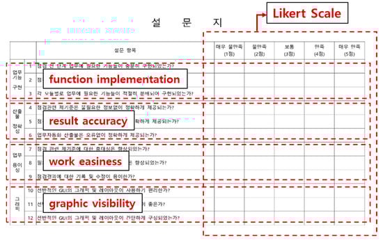
Figure 19.
Questionnaire for the system convenience assessment.
The questionnaire items were largely composed of function implementation, result accuracy, work easiness, and graphic visibility. We analyzed whether the reliability of the inspection preparation data was improved, whether manual errors were prevented by the work automation, and whether it was easier to perform the work compared to the previous method.
As shown in the survey results in Table 10, it was observed that the functions necessary for the job were sufficiently implemented in both the pre-inspection and post-inspection phases, and the functions required for the job were properly distributed and implemented for each module.
Table 10.
Survey result.
As a result of the survey on the accuracy of the products, only the information necessary for each temporary facility was provided accurately, excluding unnecessary information, and the checklist was also provided accurately, so that it could be used directly in practice without any omissions, and the list of temporary facilities was provided. The participants answered that the work automation products, such as the inspection and quantity calculation, were also provided accurately, without errors.
The ease of work was found to be significantly improved compared to the existing standards in terms of portability, standard accessibility, and the recording and editing of the inspection results. Finally, in the questionnaire about the graphic elements, the respondents answered that the convenience, readability, and configuration of the GUI were not unreasonable when performing tasks.
The respondents reflected that, if future research proceeds, the inspection record method should not simply be conducted using a checklist in the interview inquiring about what additional functions are needed to supplement the system performance, but pictures or videos should also be taken frequently. Additionally, they answered that the DB needs to be constructed in consideration of the design drawings for some temporary facilities, such as temporary retaining walls and system formwork. In addition, there was an opinion that if the quality-check-related information was not updated continuously, there would be no difference from the existing work process; thus, the relevant part should be systematically resolved.
In the future, if follow-up studies aiming to develop a system by reflecting on the additional supplements of the graphics and interface and the verification group are carried out, it is judged that the existing quality inspection task could be performed more effectively.
6. Conclusions
Because quality inspection works are performed manually, they are susceptible to human error, which is usually caused by inefficient processes. Thus, this research aims to enhance the efficiency of the quality inspection works that QM engineers perform, and it targets the movable scaffoldings, which are categorized under temporary facilities. In this study, a BIM-based quality inspection work process was proposed, and a system prototype was developed. This study is relevant because it developed a system prototype, which is the basis of the TO-BE work process, and verified its applicability by applying it to the construction field. However, to address the limitations that adversely affect quality inspection works, a thorough analysis is required. On the other hand, from a system development perspective, there was a limitation on the function of the prototype. Therefore, to enhance the proposed prototype, researchers need to explore improvements in the quality inspection process for temporary facilities and practical system development. In addition, it is very important to update the standards that must be checked in the quality inspection work. Therefore, it is also necessary to develop a system that can update and manage the database for the standards in real time.
Nevertheless, the following effects can be expected based on the results of this study:
(1) Improving the quality of temporary construction quality inspection work:
By utilizing the results of this study, the speed, accuracy, and convenience of the work can all be improved compared to the existing work process. Through this, the work procedures performed by quality control construction engineers are greatly simplified and automated, so that the quality inspection work for temporary construction can be qualitatively improved by measures such as the prevention of human error and the improvement of the work efficiency.
(2) Securing the quality of temporary facilities:
As the quality inspection work of temporary construction improves in terms of its quality, it is possible to form judgements based on accurate knowledge rather than empirically judging the items to be inspected. Therefore, it is possible to prevent pointed points and prevent poor inspections in advance, so that the stability, constructability, and quality of temporary facilities can be improved.
(3) Equalization of quality inspection work results:
Construction engineers are divided into four technical grades (beginner, intermediate, advanced, and special) according to their competency, and their ability to perform tasks is different depending on the technical grade. For this reason, the results and level of the quality inspection work for temporary construction may differ depending on the quality control construction engineer. However, if the system and work process developed in this study are used, this can act as a way to compensate for the differences in work level and ability, and as a result, it can be expected to standardize the work capacity of the construction engineers for the purpose of quality control.
Author Contributions
Conceptualization, C.H.C. and J.L.; methodology, C.H.C.; software, C.H.C.; validation, C.H.C. and J.L.; formal analysis, C.H.C.; investigation, C.H.C.; resources, C.H.C.; data curation, C.H.C.; writing—original draft preparation, C.H.C.; writing—review and editing, J.L.; visualization, C.H.C.; supervision, J.L.; project administration, J.L.; funding acquisition, J.L. All authors have read and agreed to the published version of the manuscript.
Funding
This research was supported by a grant (NRF-2019R1A2B5B01070260) funded by the National Research Foundation of Korea.
Informed Consent Statement
Informed consent was obtained from all subjects involved in the study.
Data Availability Statement
Data is contained within the article.
Conflicts of Interest
The authors declare no conflict of interest.
References
- Park, J.; Kim, O. Development on Breakdown Structure of Construction Site centered Construction Temporary Technology Index. Korean J. Constr. Eng. Manag. 2014, 14, 77–85. [Google Scholar] [CrossRef]
- Chen, K.; Reichard, G.; Akanmu, A.; Xu, X. Geo-registering UAV-captured close-range images to GIS-based spatial model for building façade inspections. Autom. Constr. 2021, 122, 103503. [Google Scholar] [CrossRef]
- Chow, J.K.; Liu, K.F.; Tan, P.S.; Su, Z.; Wu, J.; Li, Z.; Wang, Y.H. Automated defect inspection of concrete structures. Autom. Constr. 2021, 132, 103959. [Google Scholar] [CrossRef]
- Chow, J.K.; Su, Z.; Wu, J.; Li, Z.; Tan, P.S.; Liu, K.F.; Wang, Y.H. Artificial intelligence-empowered pipeline for image-based inspection of concrete structures. Autom. Constr. 2020, 120, 103372. [Google Scholar] [CrossRef]
- Hernandez, J.L.; Lerones, P.M.; Bonsma, P.; Delft, A.V.; Deighton, R.; Braun, J.D. An IFC Interoperability Framework for Self-Inspection Process in Buildings. Buildings 2018, 8, 32. [Google Scholar] [CrossRef]
- Hurtado, J.R.; Rivera, F.M.; Serrano, J.M.; Deraemaeker, A.; Valero, I. Proposal for the Deployment of an Augmented Reality Tool for Construction Safety Inspection. Buildings 2022, 12, 500. [Google Scholar] [CrossRef]
- May, K.W.; KC, C.; Ochoa, J.J.; Gu, N.; Walsh, J.; Smith, R.T.; Thomas, B.H. The Identification, Development, and Evaluation of BIM-ARDM: A BIM-Based AR Defect Management System for Construction Inspections. Buildings 2022, 12, 140. [Google Scholar] [CrossRef]
- Seo, J.; Duque, L.; Wacker, J. Drone-enabled bridge inspection methodology and application. Autom. Constr. 2018, 94, 112–126. [Google Scholar] [CrossRef]
- Tan, Y.; Li, S.; Liu, H.; Chen, P.; Zhou, Z. Automatic inspection data collection of building surface based on BIM and UAV. Autom. Constr. 2021, 131, 103881. [Google Scholar] [CrossRef]
- Wang, Y.G.; He, X.J.; He, J.; Fan, C. Virtual trial assembly of steel structure based on BIM platform. Autom. Constr. 2022, 141, 104395. [Google Scholar] [CrossRef]
- Yuan, X.; Smith, A.; Sarlo, R.; Lippitt, C.D.; Moreu, F. Automatic evaluation of rebar spacing using LiDAR data. Autom. Constr. 2021, 131, 103890. [Google Scholar] [CrossRef]
- Youn, J.; Yun, J.; Kim, J.; Lee, D. Development of Variable Side Mold for Free-Form Concrete Panel Production. Buildings 2022, 12, 728. [Google Scholar] [CrossRef]
- Zheng, Y.; Wang, S.; Zhang, P.; Xu, T.; Zhuo, J. Application of Nondestructive Testing Technology in Quality Evaluation of Plain Concrete and RC Structures in Bridge Engineering: A Review. Buildings 2022, 12, 843. [Google Scholar] [CrossRef]
- KSPUMSEM. New Dictionary of Architecture & Civil Engineering Terms; KSPUMSEM: Seoul, Korea, 2010. [Google Scholar]
- Kim, H.J.; Ahn, H.S. 3-D Temporary Facility Visualization Using BIM (Building Information Modeling) Technology. J. Constr. Eng. Proj. Manag. 2011, 1, 37–42. [Google Scholar] [CrossRef]
- Ko, K.; OH, S.H.; Lee, C.S. Application Prototype Development for the Building Safety Periodic Inspection. J. Archit. Inst. Korea Struct. Constr. 2016, 16, 63–71. [Google Scholar] [CrossRef]
- Jung, S.G. Improvement of Site Quality Control through Results Analysis of Construction Work’s Quality Inspection. Master’s Thesis, University of Seoul, Seoul, Korea, 2015. [Google Scholar]
- Lee, H.R.; Cho, D.H.; Park, S.H.; Koo, K.J. Nexus based Quality Inspection Support Model for Defect Prevention of Architectural Finishing Works. Korean J. Constr. Eng. Manag. 2017, 17, 59–67. [Google Scholar]
- Azhar, S. Building information modeling (BIM): Trends, benefits, risks, and challenges for the AEC industry. Leadersh. Manag. Eng. 2011, 11, 241–252. [Google Scholar] [CrossRef]
- Banfi, F.; Stephen, F.; Brumana, R. BIM automation: Advanced modeling generative process for complex structures. In Proceedings of the 26th International CIPA Symposium on Digital Workflows for Heritage Conservation, Ottawa, ON, Canada, 28 August–1 September 2017; pp. 9–16. [Google Scholar]
- Hamledari, H.; Ehsan, R.A.; Brenda, M. IFC-based development of as-built and as-is BIMs using construction and facility inspection data: Site-to-BIM data transfer automation. J. Comput. Civ. Eng. 2018, 32, 04017075. [Google Scholar] [CrossRef]
- Kim, K.; Cho, Y.K.; Kim, K.A. BIM-driven automated decision support system for safety planning of temporary structures. J. Constr. Eng. Manag. 2018, 144, 04018072. [Google Scholar] [CrossRef]
- Wijayakumar, M.; Himal, S.J. Automation of BIM Quantity Take-Off to Suit QS’s Requirements. In Proceedings of the Second World Construction Symposium 2013: Socio-Economic Sustainability in Construction, Colombo, Sri Lanka, 14–15 June 2013; pp. 70–80. [Google Scholar]


Publisher’s Note: MDPI stays neutral with regard to jurisdictional claims in published maps and institutional affiliations. |
© 2022 by the authors. Licensee MDPI, Basel, Switzerland. This article is an open access article distributed under the terms and conditions of the Creative Commons Attribution (CC BY) license (https://creativecommons.org/licenses/by/4.0/).