


Test and Bearing Capacity Calculation of a New Energy-Dissipated Precast Shear Wall


Abstract
:1. Introduction
2. The Design Method of “Strong Horizontal Joints, Weak Vertical Joints”
3. Experiment Design
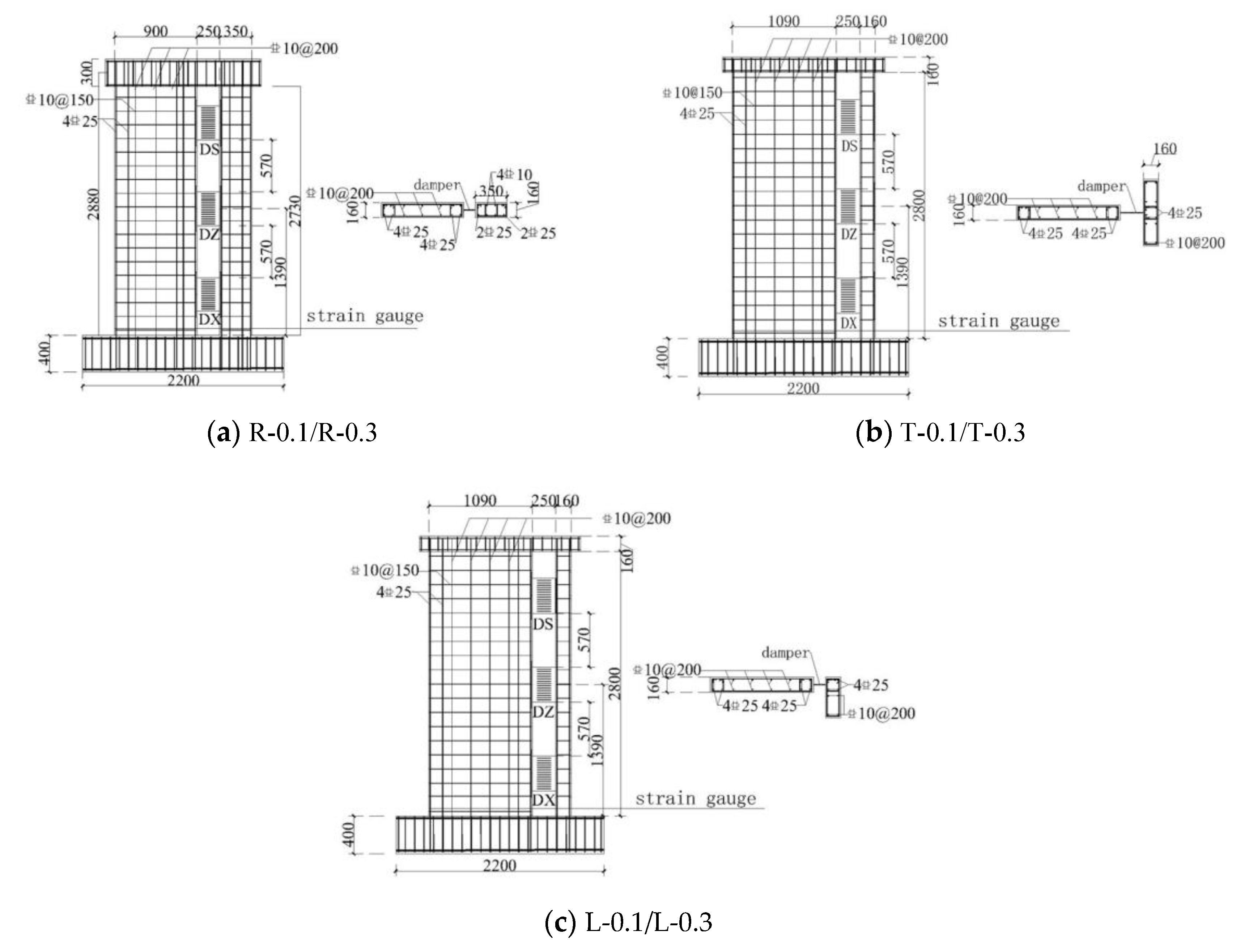
3.1. Specimen Design
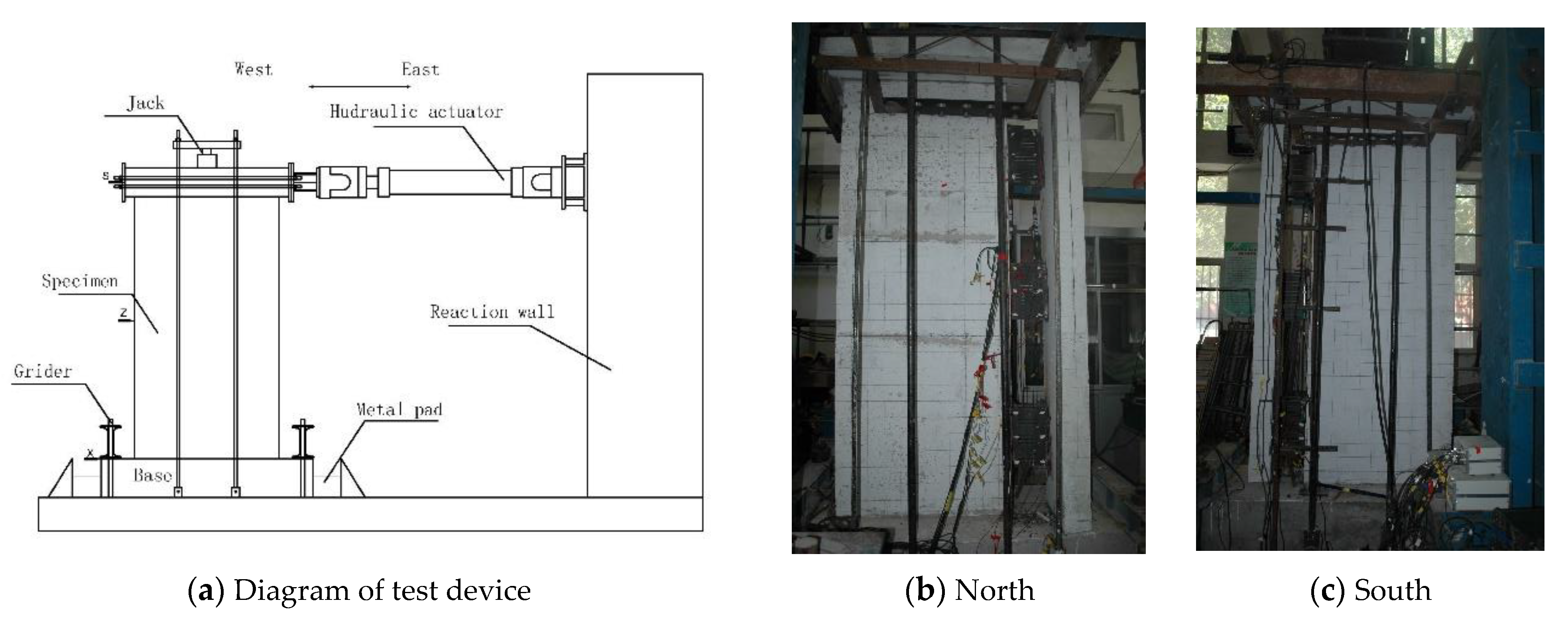
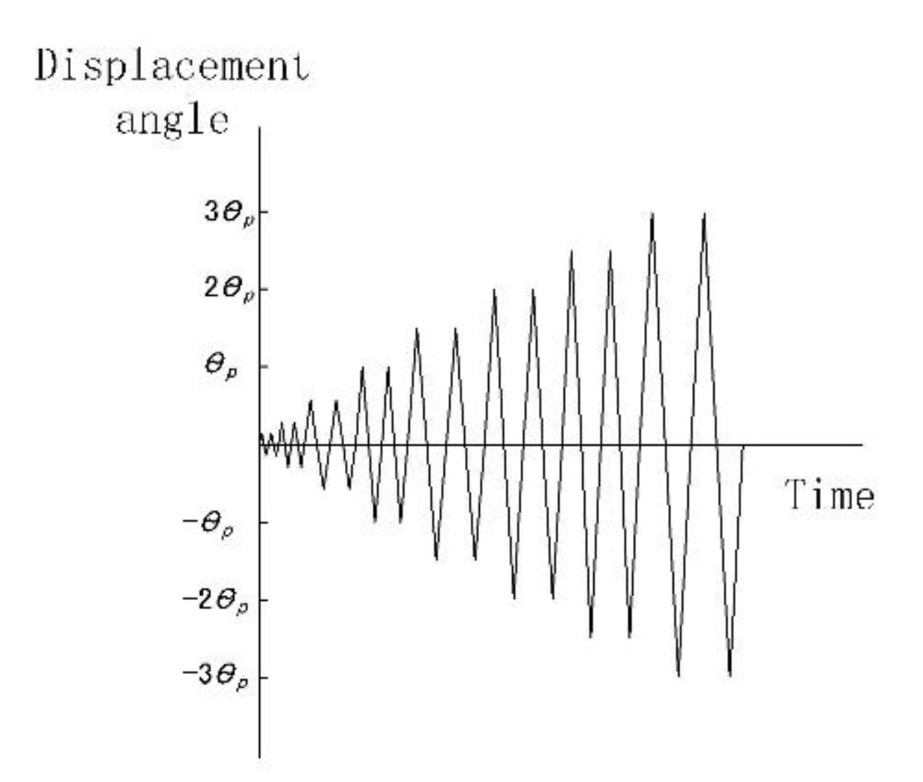
3.2. Test Setup and Loading Scheme
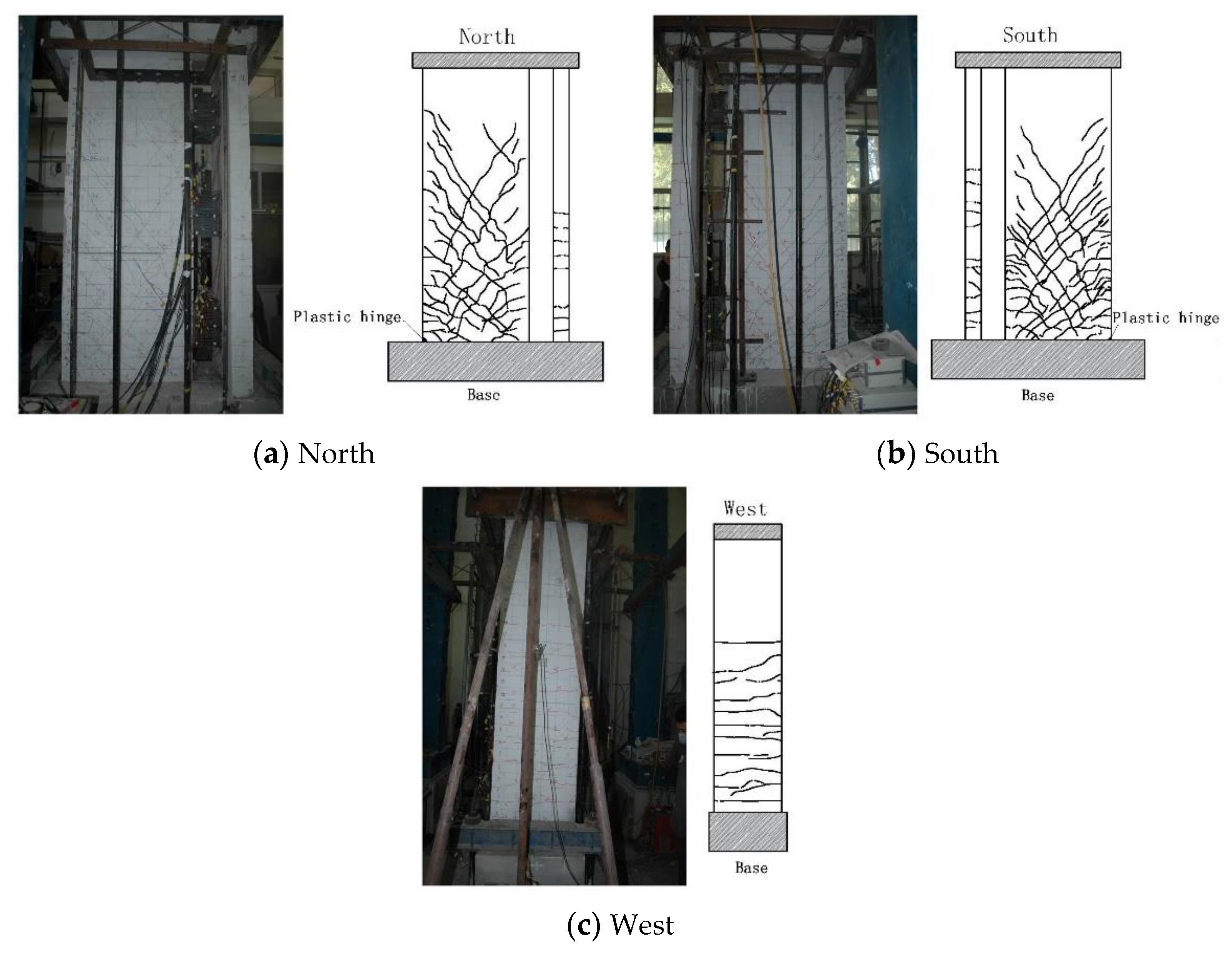
4. Failure Modes of Specimens
- (1)
- Elastic stage: The specimens and dampers of the precast shear wall specimens exhibited no prominent changes.
- (2)
- Elastoplastic stage: As the loading increased from 0.25 θp to 0.5 θp, the tensile stress at the edge of the specimen increased gradually. When the tensile strength of concrete exceeds the limit, cracks developed in the lower part of the web and larger wall. The cracks were distributed horizontally near the edge of the wall but propagated obliquely toward the center of the wall. The flange and smaller wall did not exhibit prominent cracks. As the loading increased from 0.5 θp to 1.5 θp, the position of cracks gradually moved up, and the existing cracks also gradually developed to the center of the specimen, and the crack width increased. As the loading increased from 1.5 θp to 2 θp, a plastic hinge developed in the lower part of the web and larger wall. This was accompanied by the peel-off of concrete. Horizontal cracks also developed in the flange and smaller wall, and the dampers exhibited prominent plastic deformation. For the specimens with an axial compression ratio (ACR) of 0.3, due to the large axial pressure and the concentrated loading from the jack, vertical splitting cracks developed in the upper part of the specimens, and their stress state changed. The vertical rebars were pulled out from the foundation beam due to inadequate anchoring and other reasons. This changed the mechanical properties and deformation behavior of these specimens. The vertical reinforcement bars at the edges of the T-0.1, L-0.1, and L-0.3 specimens were pulled out from the foundation beam, which had a certain impact on the mechanical properties and deformation properties of the specimens.
- (3)
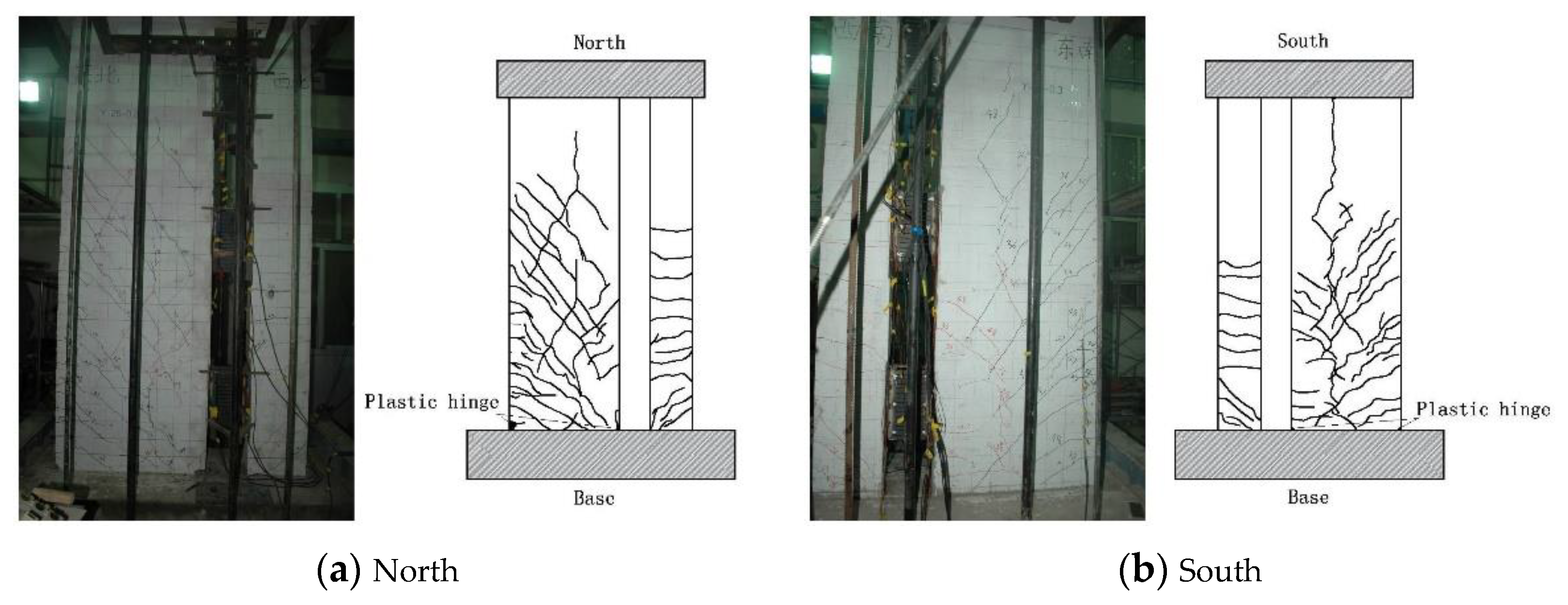
- Failure stage: When the loading increased to over 2 θp, intersecting oblique cracks occurred in the central area of the web and larger wall, the plastic-hinge area in the lower part deformed more prominently, the concrete was crushed, and the rebars were bent. Cracks penetrated horizontally across the entire width of the flange and smaller wall. The foundation beams split to different degrees. When the loading increased to over 2 θp, the loading beam of specimen R-0.1 underwent a lateral slip, the specimen underwent torsional deformation, and torsional oblique cracks developed in the smaller wall. The two ends of the dampers exhibited prominent relative displacement, and splitting occurred at the end of the bending unit. When the peak load was reached, the bearing capacity of the specimens decreased, followed by termination of the loading.
5. Test Results and Analysis
5.1. Bearing Capacity and Ductility Coefficient
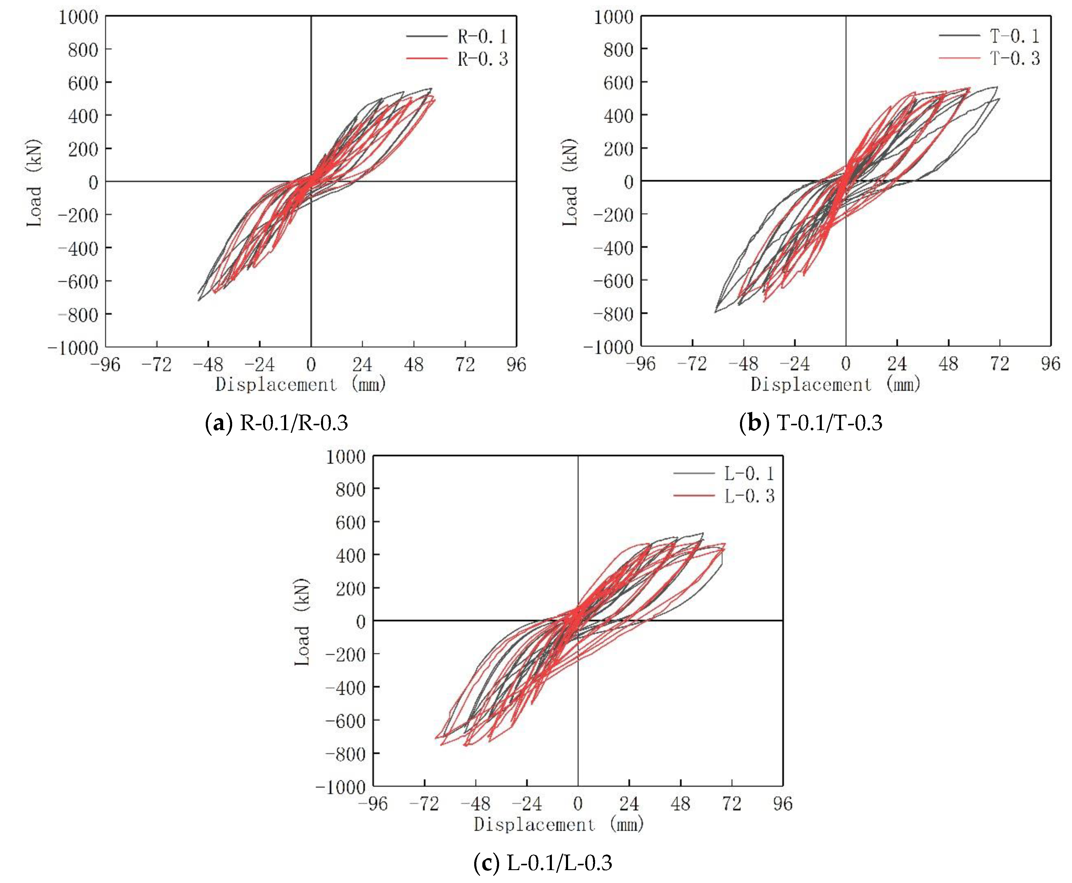
5.2. Hysteresis Curves
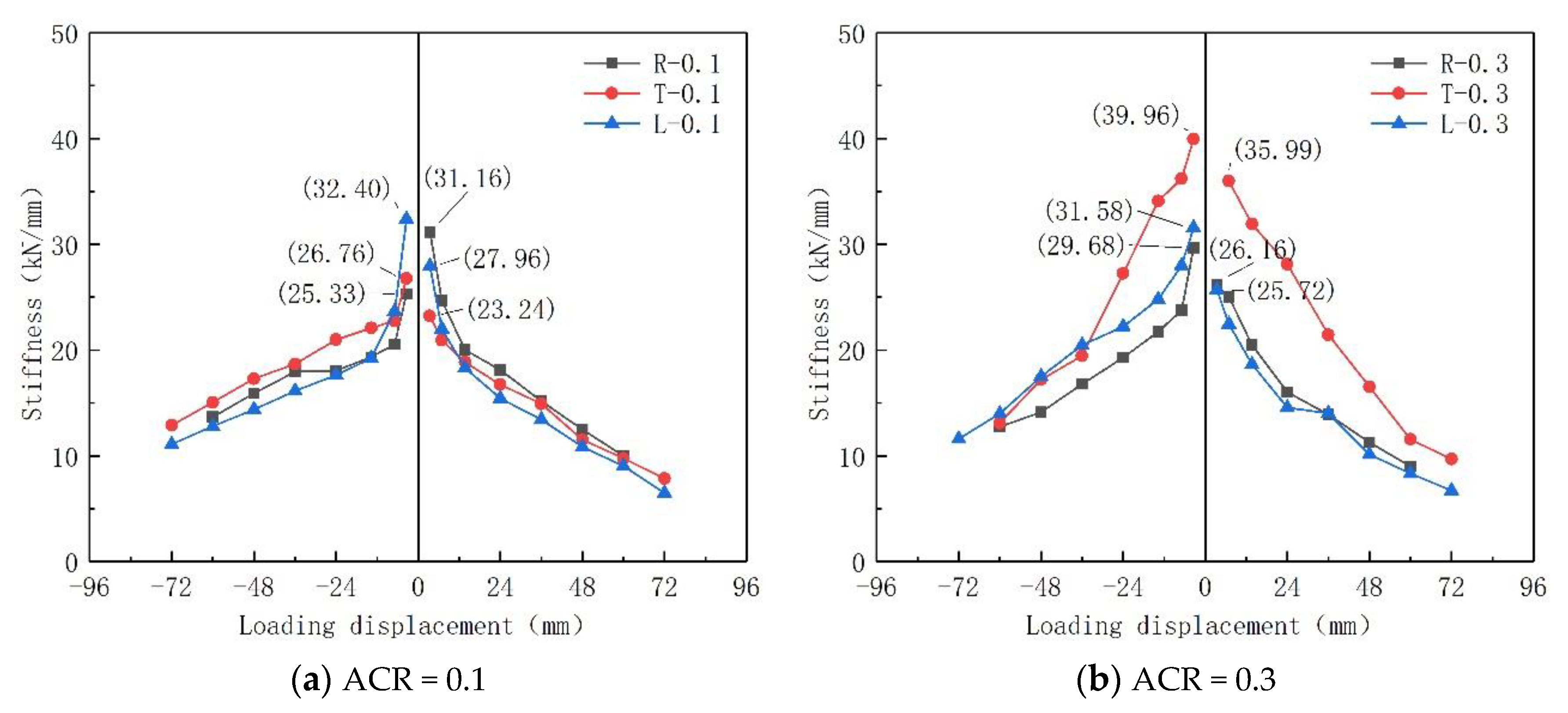
5.3. Stiffness Degradation Curves
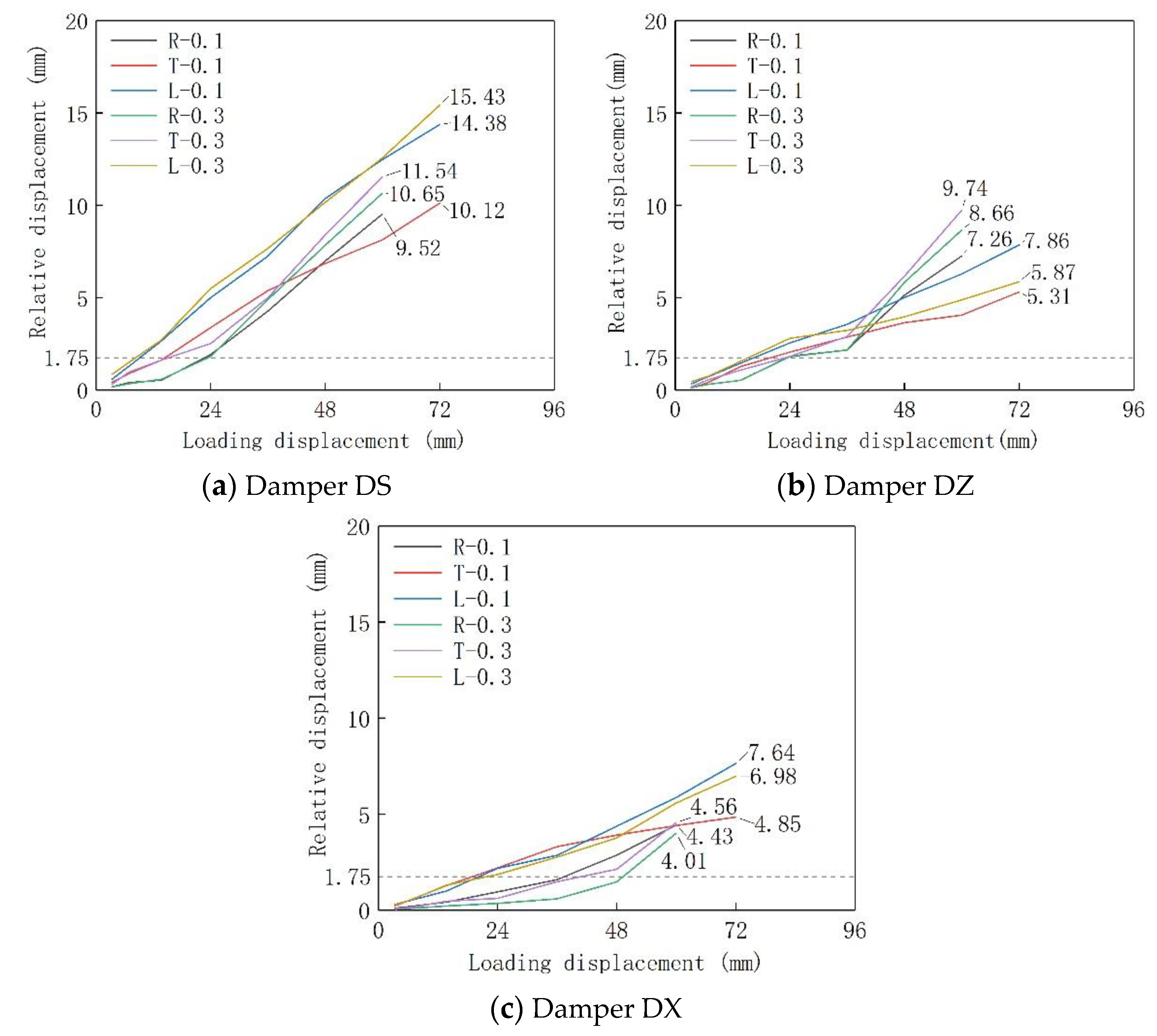
5.4. Relative Displacement of Dampers
5.5. Strain Analysis of Specimens
6. Mechanical Model for Calculation of Bearing Capacity
6.1. Calculation Model
6.2. Fundamenbtal Assumptions
- (1)
- To simplify the analysis, walls A and B of the precast shear wall structures were assumed to be identical. The cross-section of each wall remained planar after force-induced deformations; that is, each wall was consistent with the planar cross-section assumption. Each shear wall was considered as a component being subjected to eccentric forces for the calculation of its flexural bearing capacity and satisfied the various requirements set in relevant design specifications;
- (2)
- The tensile strength of the concrete in the tensile area of a wall was not considered;
- (3)
- For the calculation of the stress in the concrete in the compressive cross-sectional area, the actual concrete compressive stress diagram was substituted with an equivalent rectangular stress diagram. The average compressive stress in the compressive area of the concrete was assigned a value of α1fc. The height of the equivalent rectangular stress diagram, x, was assigned a value of β1xn. Here, fc was the axial compressive strength of the concrete; xn was the height of the actual compressive area in a pier; α1 and β1 were the coefficients of the equivalent rectangular diagram for the concrete and were assigned values of α1 = 1.0 and β1 = 0.8, respectively, when the grade of the concrete was lower than C50;
- (4)
- The strengthening effect of the dampers after yielding was not considered; that is, the post-yield bearing capacity of the dampers remained constant during the loading;
- (5)
- For the T-shaped and L-shaped specimens, the flange was considered as a component being subjected to an eccentric force, and all rebars in the flange were assumed to yield during ensile (compressive) loading. The bearing capacity of the flange can also be determined using the calculation model shown in Figure 16.
6.3. Calculation of Bearing Capacity
6.3.1. Large Eccentric Compression-Induced Failure
6.3.2. Large Eccentric Tension-Induced Failure
6.4. Analysis of Flexural Bearing Capacity in Normal Cross-Sections
7. Conclusions and Prospect
- (1)
- The bearing capacity of the specimen under positive loading is greater than 500 kN, and under negative loading is greater than 700 kN. The bearing capacity of the specimens is good. Due to the difference between the two wall limbs, the bearing capacity of the specimen in the two directions is different. Therefore, the two wall limbs should be close to each other so that the bearing capacity of the specimen in the two loading directions is similar. With the increase of ACR, the bearing capacity of the specimen increases, but the ductility decreases.
- (2)
- When the plastic hinge begins to appear at the lower part of the wall limbs, the displacement angle is about 1/60, which is twice the maximum elastic–plastic interlayer displacement angle (1/120) required by the code. When the specimen finally fails, the displacement angle is 1/40. The ductility coefficient is larger under positive loading and smaller under negative loading. Furthermore, the DDC of the specimen is close to or greater than three, indicating good ductility.
- (3)
- All dampers have reached yield, which played a role in improving the seismic performance of the structure. The dampers DS and DZ had reached yield before the failure of the specimen, which played an important role in alleviating the failure of the wall limbs. The damper DX yield late and served more to connect the wall limbs. The maximum relative displacement of the damper was 15.43 mm, which did not reach the ultimate displacement (20.19 mm) of the damper. The dampers functioned well as connectors at the failure of the specimens, securing the overall properties of the structure.
- (4)
- The simplified mechanical model of the precast shear wall structure is given, and the calculation formula of the bearing capacity is derived. The experimental results are compared with the calculated results, which show that the calculation method can better reflect the bearing capacity of the structure.
Author Contributions
Funding
Institutional Review Board Statement
Informed Consent Statement
Data Availability Statement
Conflicts of Interest
References
- Li, A.Q.; Wang, W.; Jia, H.; Chen, M.F.; Zheng, J. Progress of investigation on seismic behavior of precast RC shear wall structures(I): Joint property study. J. Disaster Prev. Mitig. Eng. 2013, 33, 600–605. [Google Scholar] [CrossRef]
- Soudki, K.A.; West, J.S.; Rizkalla, S.H.; Blackett, B. Horizontal connections for precast concrete shear wall panels under cyclic shear loading. PCI J. 1996, 41, 64–80. [Google Scholar] [CrossRef]
- Wang, W.; Li, A.Q.; Wang, X.X. Seismic performance of precast concrete shear wall structure with improved assembly horizontal wall connections. Bull. Earthq. Eng. 2018, 16, 4133–4158. [Google Scholar] [CrossRef]
- Marriott, D.J.; Pampanin, S.; Palermo, A.; Bull, D. Shake-Table Testing of Hybrid Post-Tensioned Precast Wall Systems with Alternative Dissipating Solutions. In Proceedings of the 14th World Conference on Earthquake Engineering, Beijing, China, 12–17 October 2008. [Google Scholar]
- Henin, E.; Morcous, G. Non-proprietary bar splice sleeve for precast concrete construction. Eng. Struct. 2015, 83, 154–162. [Google Scholar] [CrossRef]
- Kisa, M.H.; Yuksel, S.B.; Caglar, N. Experimental study on hysteric behavior of composite shear walls with steel sheets. J. Build. Eng. 2020, 33, 101570. [Google Scholar] [CrossRef]
- Buddika, H.A.D.S.; Wijeyewickrema, A.C. Seismic shear force amplification in post-tensioned hybrid precast walls. J. Struct. Eng. 2018, 144, 04018086. [Google Scholar] [CrossRef]
- Jiang, H.J.; Li, S.R.; Bolander, J.E.; Kunnath, S.K. Seismic Performance of a New Type of Coupled Shear Wall with Replaceable Components: Experimental Validation. J. Earthq. Eng. 2022. [Google Scholar] [CrossRef]
- Biswal, A.; Prasad, A.M.; Sengupta, A.K. Study of shear behavior of grouted vertical joints between precast concrete wall panels under direct shear loading. Struct. Concr. 2019, 20, 564–582. [Google Scholar] [CrossRef]
- Zhu, Z.F.; Guo, Z.X. Seismic performance of the spatial model of precast concrete shear wall structure using grouted lap splice connection and cast-in-situ concrete. Struct. Concr. 2019, 20, 1316–1327. [Google Scholar] [CrossRef]
- Crisafulli, F.J.; Restrepo, J.I. Ductile steel connections for seismic resistant precast buildings. J. Earthq. Eng. 2003, 7, 541. [Google Scholar] [CrossRef]
- Zhang, C.; Li, H.; Gao, W.; Li, C. Experimental and analytical investigations on new viscoelastic damped joints for seismic mitigation of structures with precast shear walls. Struct. Control Health Monit. 2019, 27, e2485. [Google Scholar] [CrossRef]
- Li, J.; Wang, Y.; Lu, Z.; Li, J. Experimental Study and Numerical Simulation of a Laminated Reinforced Concrete Shear Wall with a Vertical Seam. Appl. Sci. 2017, 7, 629. [Google Scholar] [CrossRef] [Green Version]
- Mirsadeghi, M.; Fanaie, N. Steel plate shear walls with partial length connection to vertical boundary element. Structures 2021, 32, 1820–1838. [Google Scholar] [CrossRef]
- Henry, R.S.; Aaleti, S.; Sritharan, S.; Ingham, J.M. Concept and Finite-element Modeling of New Steel Shear Connectors for Self-centering Wall Systems. J. Eng. Mech. 2010, 136, 220–229. [Google Scholar] [CrossRef]
- Marriott, D.; Pampanin, S.; Bull, D.; Palermo, A. Dynamic Testing of Precast, Post-tensioned Rocking Wall Systems with Alternative Dissipating Solutions. Bull. N. Z. Soc. Earthq. Eng. 2008, 41, 90–103. [Google Scholar] [CrossRef] [Green Version]
- Pantelides, C.P.; Volnyy, V.A.; Gergely, J.; Reaveley, L.D. Seismic retrofit of precast concrete panel connections with carbon fiber reinforced polymer composites. PCI J. 2003, 48, 92–101. [Google Scholar] [CrossRef] [Green Version]
- Chung, H.S.; Moon, B.W.; Lee, S.K.; Park, J.H.; Min, K.W. Seismic Performance of Friction Dampers Using Flexure of RC Shear Wall System. Struct. Des. Tall Spec. Build. 2009, 18, 807–822. [Google Scholar] [CrossRef]
- Sun, J.; Qiu, H.; Lu, Y.; Jiang, H. Experimental study of lateral load behavior of H-shaped precast reinforced concrete shear walls with bolted steel connections. Struct. Des. Tall Spec. Build. 2019, 28, e1663. [Google Scholar] [CrossRef]
- Sun, J.; Qiu, H.X.; Jiang, H.B. Experimental study and associated mechanism analysis of horizontal bolted connections involved in a precast concrete shear wall system. Struct. Concr. 2019, 20, 282–295. [Google Scholar] [CrossRef] [Green Version]
- Gu, Q.; Dong, G.; Ke, Y.; Tian, S.; Wen, S.; Tan, Y.; Gao, X. Seismic behavior of precast double-face superposed shear walls with horizontal joints and lap spliced vertical reinforcement. Struct. Concr. 2020, 21, 1973–1988. [Google Scholar] [CrossRef]
- Wang, Y.L.; Cui, H.J.; Zhang, Y.M.; Ding, Z.X. Analysis and experimental study on mechanical properties of mild damper with different slit forms. Ind. Constr. 2019, 49, 170. [Google Scholar] [CrossRef]
- GB50011-2010; Code for Seismic Design of Buildings. China Academy of Building Research: Beijing, China; Ministry of Construction of the People’s Republic of China: Beijing, China, 2016.
- GB50010-2010; Code for Design of Concrete Structures. China Academy of Building Research: Beijing, China; Ministry of Construction of the People’s Republic of China: Beijing, China, 2015.
- JGJT101-2015; Specification for Seismic Test of Buildings. China Academy of Building Research: Beijing, China; Ministry of Construction of the People’s Republic of China: Beijing, China, 2015.
- Li, M. Study on the Design Method of Silt Shear Walls with Metal Dampers. Master’s Thesis, Southeast University, Nanjing, China, 2017. [Google Scholar]
- Yan, X.Y. Study on Seismic Behavior of Fabricated Shear Wall with Vertical Energy-Consuming Joints. Master’s Thesis, Southeast University, Nanjing, China, 2019. [Google Scholar]
- JGJ3-2010; Technical Specification for Concrete Structures of Tall Building. China Academy of Building Research: Beijing, China; Ministry of Construction of the People’s Republic of China: Beijing, China, 2010.


| Specimens | Number | Concrete | Vertical Slit Width/mm | ACR |
|---|---|---|---|---|
| Rectangle | R-0.1 | C40 | 250 | 0.1 |
| R-0.3 | C40 | 250 | 0.3 | |
| T-shape | T-0.1 | C40 | 250 | 0.1 |
| T-0.3 | C40 | 250 | 0.3 | |
| L-shape | L-0.1 | C40 | 250 | 0.1 |
| L-0.3 | C40 | 250 | 0.3 |
| Yield Load | Yield Displacement | Ultimate Load | Ultimate Displacement | Initial Stiffness |
|---|---|---|---|---|
| 55.76 | 1.75 | 94.72 | 20.19 | 31.86 |
| Diameter | Yield Stress | Ultimate Stress | Yield Strength ratio |
|---|---|---|---|
| 10 | 473 | 696 | 1.47 |
| 25 | 465 | 658 | 1.42 |
| Concrete | ||
|---|---|---|
| C40 | 41.8 | 27.96 |
| Number | Displacement Angle | Loading Displacement/mm | Cycle-Index | Time/s |
|---|---|---|---|---|
| 1 | 1/840 (0.12 θp) | 3.4 | 2 | 6.8 × 8 = 54.4 |
| 2 | 2/840 (0.25 θp) | 6.9 | 2 | 13.8 × 8 = 110.4 |
| 3 | 4/840 (0.5 θp) | 13.7 | 2 | 27.4 × 8 = 219.2 |
| 4 | 7/840 (θp) | 24 | 2 | 48 × 8 = 384 |
| 5 | 10.5/840 (1.5 θp) | 36 | 2 | 72 × 8 = 576 |
| 6 | 14/840 (2 θp) | 48 | 2 | 96 × 8 = 768 |
| 7 | 17.5/840 (2.5 θp) | 60 | 2 | 120 × 8 = 960 |
| 8 | 21/840 (3 θp) | 72 | 2 | 144 × 8 = 1152 |
| Number | Cracking Load /kN | Cracking Displacement | Yield Load /kN | Yield Displacement | Peak Load | Peak Displacement | Ductility Factor μ | ||||
|---|---|---|---|---|---|---|---|---|---|---|---|
| R-0.1 | + | 166.81 | 6.74 | 1/427 | 328.07 | 17.36 | 1/166 | 562.58 | 56.34 | 1/51 | 3.25 |
| − | 132.74 | 6.20 | 1/465 | 338.50 | 18.46 | 1/156 | 720.57 | 52.65 | 1/55 | 2.85 | |
| R-0.3 | + | 168.09 | 8.33 | 1/347 | 273.93 | 17.02 | 1/169 | 514.85 | 58.06 | 1/50 | 3.41 |
| − | 133.90 | 6.73 | 1/428 | 421.25 | 18.26 | 1/158 | 679.39 | 54.47 | 1/53 | 2.98 | |
| T-0.1 | + | 173.90 | 6.83 | 1/422 | 380.39 | 19.89 | 1/145 | 568.45 | 70.92 | 1/41 | 3.56 |
| − | 207.73 | 9.16 | 1/314 | 455.03 | 21.46 | 1/134 | 798.07 | 61.49 | 1/47 | 2.87 | |
| T-0.3 | + | 216.96 | 6.87 | 1/419 | 414.76 | 17.88 | 1/161 | 563.70 | 58.08 | 1/50 | 3.25 |
| − | 349.20 | 9.06 | 1/318 | 538.98 | 18.21 | 1/158 | 735.74 | 50.80 | 1/57 | 2.79 | |
| L-0.1 | + | 159.71 | 6.97 | 1/413 | 320.48 | 19.87 | 1/145 | 529.93 | 58.65 | 1/49 | 2.95 |
| − | 151.87 | 7.45 | 1/387 | 355.30 | 20.06 | 1/144 | 702.47 | 63.34 | 1/45 | 3.16 | |
| L-0.3 | + | 199.96 | 9.95 | 1/289 | 396.54 | 19.03 | 1/151 | 473.13 | 68.92 | 1/42 | 3.62 |
| − | 263.52 | 10.59 | 1/272 | 457.57 | 19.46 | 1/148 | 758.28 | 64.40 | 1/45 | 3.31 | |
| Displacement Angle | Relative Displacement of Dampers/mm | |||||
|---|---|---|---|---|---|---|
| R-0.1 | T-0.1 | L-0.1 | R-0.3 | T-0.3 | L-0.3 | |
| 0.12 θp | 0.17 | 0.43 | 0.59 | 0.17 | 0.32 | 0.85 |
| 0.25 θp | 0.40 | 0.89 | 1.28 | 0.34 | 0.96 | 1.50 |
| 0.5 θp | 0.53 | 1.63 | 2.66 | 0.58 | 1.62 | 2.71 |
| 1.0 θp | 1.91 | 3.37 | 4.99 | 1.81 | 2.51 | 5.49 |
| 1.5 θp | 4.27 | 5.38 | 7.24 | 4.89 | 4.99 | 7.67 |
| 2.0 θp | 6.99 | 6.85 | 10.37 | 7.84 | 8.39 | 10.15 |
| 2.5 θp | 9.52 | 8.13 | 12.48 | 10.65 | 11.54 | 12.57 |
| 3.0 θp | — | 10.12 | 14.38 | — | — | 15.43 |
| Displacement Angle | Relative Displacement of Dampers/mm | |||||
|---|---|---|---|---|---|---|
| R-0.1 | T-0.1 | L-0.1 | R-0.3 | T-0.3 | L-0.3 | |
| 0.12 θp | 0.13 | 0.12 | 0.33 | 0.13 | 0.17 | 0.46 |
| 0.25 θp | 0.31 | 0.40 | 0.72 | 0.31 | 0.55 | 0.74 |
| 0.5 θp | 0.53 | 1.27 | 1.45 | 0.52 | 1.07 | 1.55 |
| 1.0 θp | 1.83 | 2.05 | 2.55 | 1.80 | 1.81 | 2.80 |
| 1.5 θp | 2.17 | 2.87 | 3.56 | 2.17 | 2.90 | 3.22 |
| 2.0 θp | 5.13 | 3.64 | 5.01 | 5.83 | 6.16 | 3.96 |
| 2.5 θp | 7.26 | 4.06 | 6.28 | 8.66 | 9.74 | 4.88 |
| 3.0 θp | — | 5.31 | 7.86 | — | — | 5.87 |
| Displacement Angle | Relative Displacement of Dampers/mm | |||||
|---|---|---|---|---|---|---|
| R-0.1 | T-0.1 | L-0.1 | R-0.3 | T-0.3 | L-0.3 | |
| 0.12 θp | 0.10 | 0.22 | 0.29 | 0.04 | 0.07 | 0.28 |
| 0.25 θp | 0.21 | 0.58 | 0.53 | 0.10 | 0.15 | 0.57 |
| 0.5 θp | 0.42 | 1.28 | 0.99 | 0.22 | 0.47 | 1.30 |
| 1.0 θp | 0.95 | 2.20 | 2.18 | 0.35 | 0.61 | 1.85 |
| 1.5 θp | 1.59 | 3.31 | 2.86 | 0.59 | 1.49 | 2.76 |
| 2.0 θp | 2.87 | 3.91 | 4.37 | 1.47 | 2.13 | 3.76 |
| 2.5 θp | 4.43 | 4.41 | 5.86 | 4.01 | 4.56 | 5.58 |
| 3.0 θp | — | 4.85 | 7.64 | — | — | 6.98 |
| Number | Test Results/kN | Calculation Results/kN | Test Results/Calculation Results | |||
|---|---|---|---|---|---|---|
| + | − | + | − | + | − | |
| R-0.1 | 562.58 | 720.57 | 519 | 626 | 0.92 | 0.87 |
| R-0.3 | 514.85 | 679.39 | 668 | 811 | 1.30 | 1.19 |
| T-0.1 | 568.45 | 798.07 | 581 | 732 | 1.02 | 0.92 |
| T-0.3 | 563.70 | 735.74 | 779 | 947 | 1.38 | 1.28 |
| L-0.1 | 529.93 | 702.47 | 550 | 698 | 1.04 | 0.99 |
| L-0.3 | 473.13 | 758.28 | 772 | 940 | 1.63 | 1.24 |
Publisher’s Note: MDPI stays neutral with regard to jurisdictional claims in published maps and institutional affiliations. |
© 2022 by the authors. Licensee MDPI, Basel, Switzerland. This article is an open access article distributed under the terms and conditions of the Creative Commons Attribution (CC BY) license (https://creativecommons.org/licenses/by/4.0/).
Share and Cite
Wang, Y.; Wang, Z.; Zhou, Y.; Yang, Z.; Zhang, Y. Test and Bearing Capacity Calculation of a New Energy-Dissipated Precast Shear Wall. Buildings 2022, 12, 1990. https://doi.org/10.3390/buildings12111990
Wang Y, Wang Z, Zhou Y, Yang Z, Zhang Y. Test and Bearing Capacity Calculation of a New Energy-Dissipated Precast Shear Wall. Buildings. 2022; 12(11):1990. https://doi.org/10.3390/buildings12111990
Chicago/Turabian StyleWang, Yuliang, Zhaohui Wang, Yunlong Zhou, Zhinian Yang, and Yumin Zhang. 2022. "Test and Bearing Capacity Calculation of a New Energy-Dissipated Precast Shear Wall" Buildings 12, no. 11: 1990. https://doi.org/10.3390/buildings12111990