1. Introduction
Three-dimensional concrete printing (3DCP) [
1], also known as 3D printed concrete (3DPC) [
2,
3] or 3D printable cementitious material (3DPCM) [
4], was established in the late 1990s and early 2000s [
4]. Since that time, additive manufacturing has been used worldwide. The rapid development of 3D concrete printing technology has provided the building and construction industry with a concept that matches the requirements of Industry 4.0, which is transformation of production utilizing the digitization of manufacturing.
Although intensive research and development is still being carried out, there are still challenges regarding the technical, economic and environmental aspects of 3D concrete printing [
5]. The technical challenges in the field of 3D printing can be mentioned as follows: the issues related to the optimization of the material composition of mixtures, active control of rheological properties and stiffening of the fresh cementitious material, appropriate curing conditions of 3D printed elements and structures, weakness of the technology presented by the interface strength between the printed layers, needs for quality control methods, stability and durability of printed elements and structures or reinforcement possibilities. Economic and social aspects concern the high potential for increased productivity due to the use of robotic and automation systems and changes in the cost structure. Environmental potential lies in sustainability and the need to reduce: greenhouse gas emissions, energy consumption, waste generation and water depletion [
5,
6].
Authors [
2,
6] have reported that previous studies have shown the advantages of 3D concrete printing compared with conventional construction methods, owing to reduction in up to 80% of labor costs, 70% of production time and up to 60% of construction waste. However, a higher content of the Portland cement with other admixtures and additives is used in 3D concrete printing [
7]. Based on a literature review [
8,
9,
10,
11,
12,
13,
14,
15,
16] Portland cement has been a standard choice of binder. To ensure sufficient buildability and workability, superplasticizer and hydroxypropyl methylcellulose have been added to obtain a mixture with suitable workability and open-time [
5,
9,
11]. The EU has agreed to reduce emissions by at least 55% by 2030 as part of the “Fit for 55” package, and therefore the building and construction industry will have to find new ways to reduce Portland cement consumption. An environmentally friendly approach, reducing the carbon footprint in the field of 3D concrete printing, presents partial replacement of Portland cement by supplementary cementitious materials and the use of recycled aggregate [
8,
9]. The most commonly used supplementary cementitious materials have been fly ash from coal combustion, silica fume, granulated blast furnace slag [
7,
8] but also limestone or burnt oil shale can be used [
8]. Recent studies demonstrated that the incorporation of recycled coarse aggregate (obtained from demolished concrete structures) [
10], recycled sand (acquired by crushing waste concrete) [
11], recycled brick aggregate [
12], recycled PET aggregate [
13], recycled waste glass [
14], and recycled waste tires [
15] are beneficial to 3D concrete printing. Addition of fly ash has a positive effect on properties of fresh mixture (improved mixture workability): shrinkage reducing, lower porosity, better mechanical properties and a considerably positive influence on the durability of printed elements and structures (higher resistance to chemicals, acids, sulfates, carbon and thermal environments) [
4,
12]. The fibers (basalt, glass, carbon, steel, polyvinyl alcohol, polypropylene) are able to provide the tensile strength and the ductility that are required by the application [
17,
18].
Although 3D concrete printing has become a technology used worldwide, both industry and the scientific community are intensively involved in the optimization of material design, testing methods and technical specifications. [
16]. Properties in fresh state testing such as the flow-table test, shape-retention test, yield stress, thixotropy, viscosity, green strength test [
18,
19], penetration test, and slugs test [
20] were conducted. The authors [
19] investigated the fresh properties and the findings obtained from this experimental study of 3D printable cementitious material showed no relationship between yield stress, thixotropy and viscosity properties [
19]. The standard procedure for testing buildability has not been established yet [
8]. Therefore, considerable attention is devoted to finding suitable indirect methods for evaluating the fresh and hardened properties of 3D printed cementitious materials which could contribute to further acceptance of 3D printing as a construction technology by buildings and construction authorities [
17,
18,
21].
Superabsorbent polymers (SAPs) are characterized by the ability to absorb, retain and release a significant amount of water or aqueous solution [
22]. SAP, after being utilized in several industries (sanitary, agriculture, medical), are promising multipurpose admixtures for cement-based mortars and concrete [
23,
24]. The use of SAP as an additive for cementitious composites contributes to the control of the rheological properties of fresh mixture and to the mitigation of shrinkage [
24]. Authors [
25] demonstrated substantial additional reduction in plastic, autogenous and drying shrinkage by using SAP in fiber-reinforced mortars containing supplementary cementitious materials. Three types of commercial cements were used in this study: CEM I, CEM II and CEM III. Reduction of drying shrinkage is more pronounced for mortars containing CEM II.
Based on the existing knowledge, it can be concluded that the combination of superabsorbent polymer, fly ash and the cement type CEM II may be usable for the design of 3D printed cementitious composite. This new combination represents a different approach to the design of 3D printed cement-based material.
The main object of this study is to verify the new possibility of 3DCP mixtures modifications by SAPs in combination with high temperature fly ash. This study also tests the possibility of CEM II (with lower Portland clinker content than traditionally used CEM I) utilization as binder for these newly developed 3DCP mixtures, in order to reduce the consumption of Portland clinker and thereby reduce CO2 emissions, which is a very topical issue that is currently being addressed in the concrete industry worldwide.
3. Methods
The spectrum of methods described below was used in order to determine the parameters of the designed mixtures for 3D printing containing a small amount of SAP and fly ash. The determination was carried out in the fresh (ultrasound analysis, consistency, volumetric weight and buildability) and hardened state (compressive strength, tensile strength after bending and XRD analysis).
3.1. Consistency
Consistency of fresh mixtures was determined by the flow table test according to the EN 1015-3 Methods of test for mortar for masonry—Part 3: Determination of consistence of fresh mortar [
26] (by flow table) standard.
3.2. Volumetric Weight
Volumetric weight of all tested mixtures was determined in the fresh state according to the EN 1015-6:1998/A1:2006—Methods of test for mortar for masonry—Part 6: Determination of bulk density of fresh mortar [
27] standard, and hardened state according to the EN 1015-10:2001—Methods of test for mortar for masonry—Part 10: Determination of dry bulk density of hardened mortar [
28] standard.
3.3. Ultrasonic Analysis
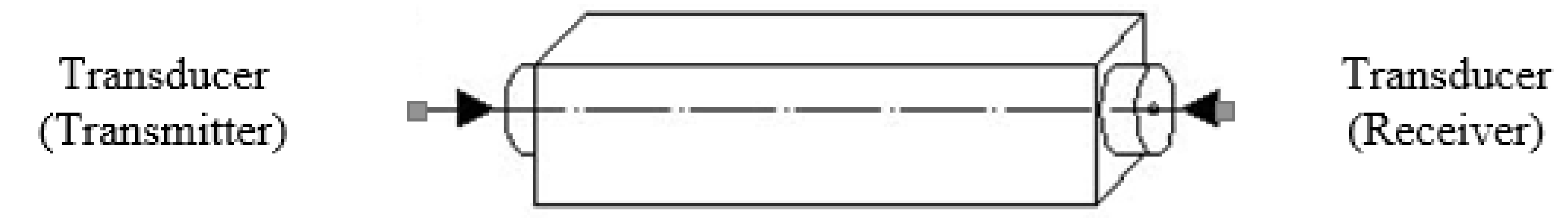
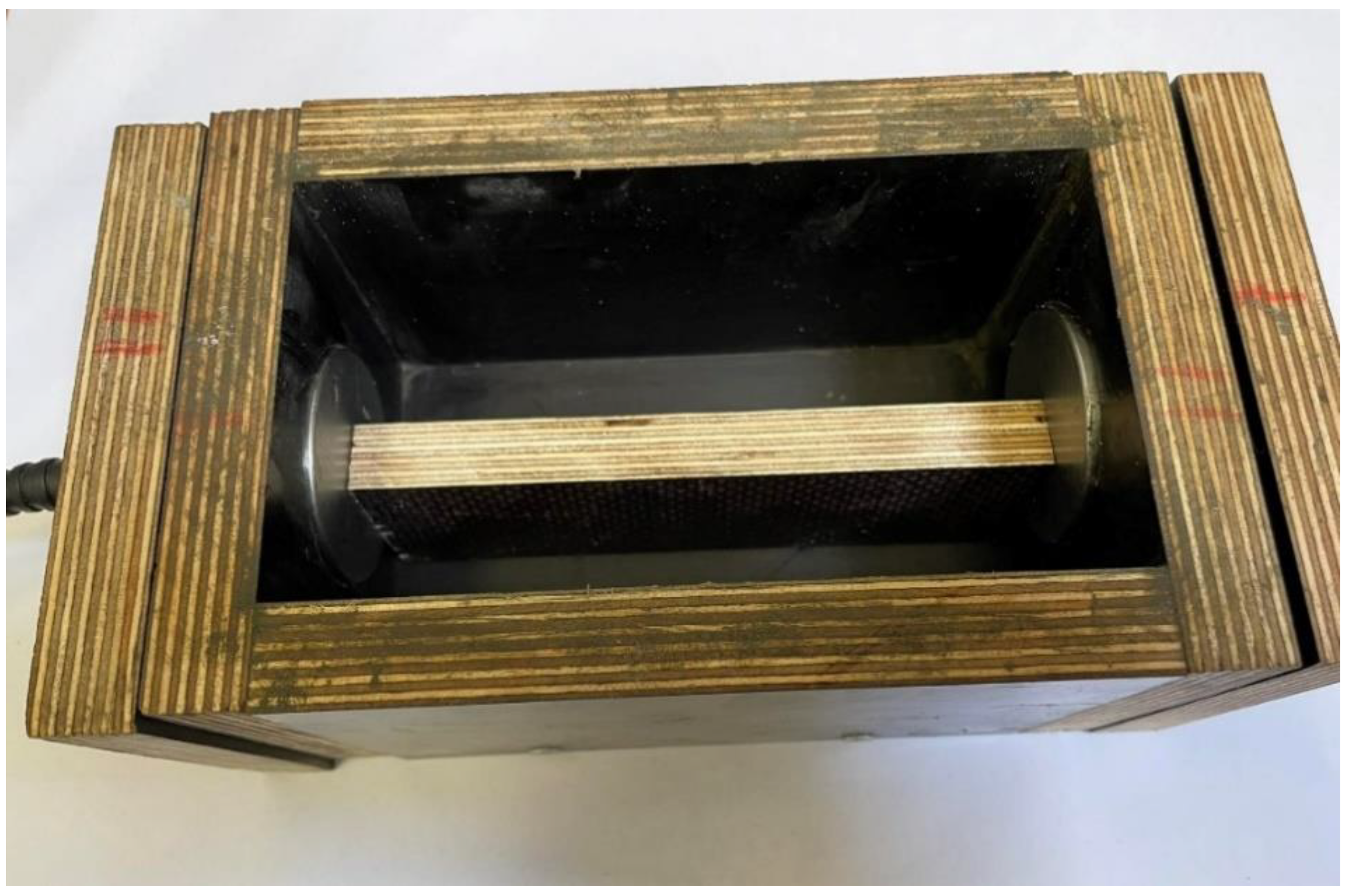
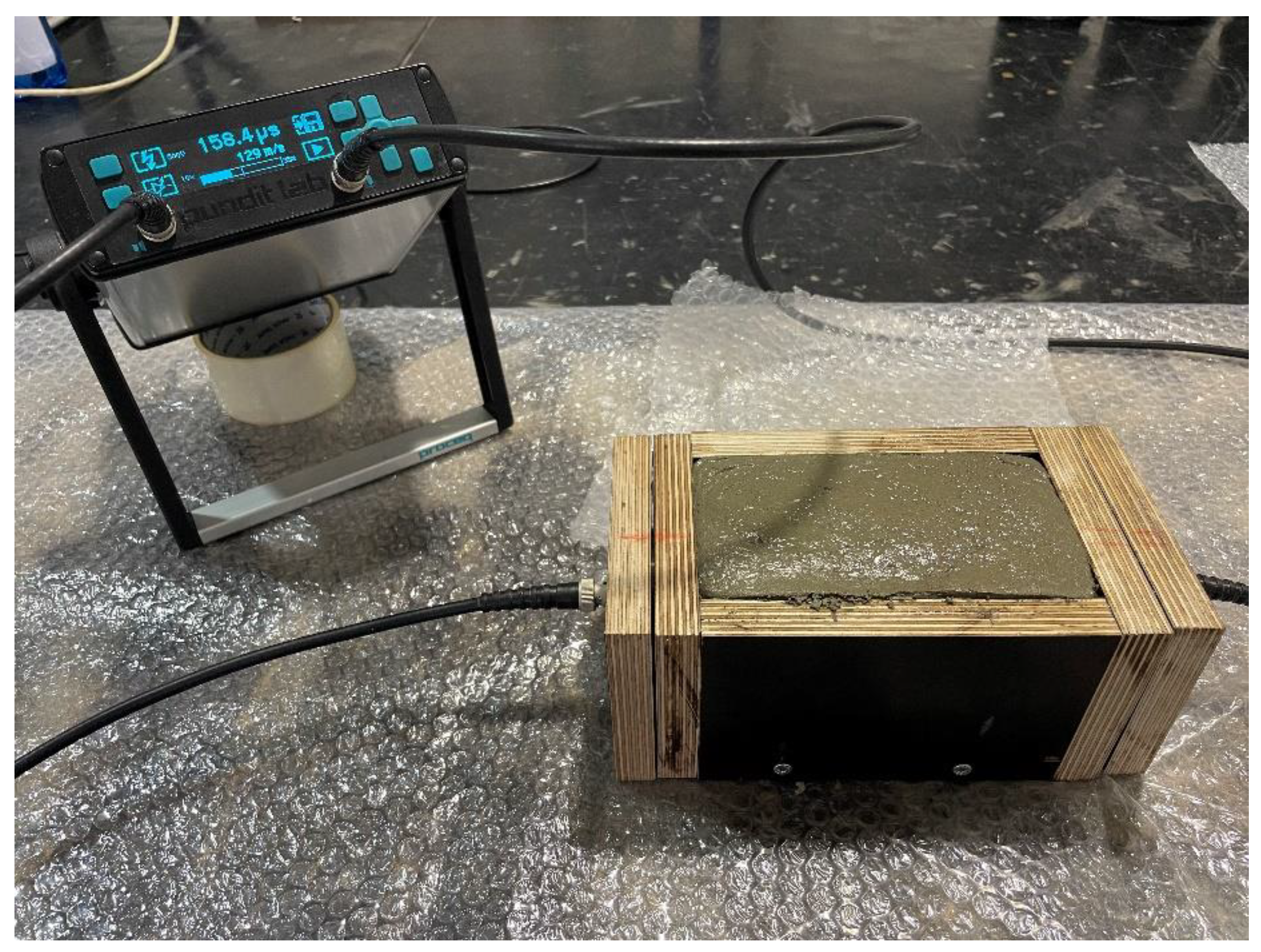
Monitoring of the velocity of propagation of the ultrasonic pulse and the dynamic modulus of elasticity of fresh mortar over time, from measurements by the ultrasonic pulse method, was used in order to monitor early stages of hydration of the tested mixtures. Measuring equipment consisted of two probes located in the faces of a cuboid cell with dimensions of 80 × 80 × 150 mm.
The course of the propagation speed of the ultrasonic pulse and the related dynamic modulus of elasticity were determined by the ultrasonic pulse method. The methodology for measuring the propagation speed of the ultrasonic pulse was based on EN 12504-4 [
29] and the dynamic modulus of elasticity was calculated according to the procedure noted in ČSN 731371 [
30]. The mentioned standards are intended for testing hardened concrete. The measurement was carried out by direct transmission—see
Figure 3.
For testing fresh mortar, the measurement procedure using the ultrasonic pulse method was modified as follows.
Fresh mortar was placed in a cell with 50 mm diameter holes made in its faces to accommodate 50 mm diameter probes. The measurement was carried out by the apparatus PUNDIT LAB for determination of transit time with an accuracy of 0.1 µm and a probe frequency of 54 kHz. The distance between the probes was set to 145 mm (length of measuring base) using the standard, and the probes were locked. The mold with fitted probes is shown in
Figure 4.
Technical vaseline was used for acoustic coupling, which was applied to the surface of the probes.
Subsequently, the mold was filled with fresh mortar, which was compacted by tamping to achieve a good acoustic bond, the upper surface of the mortar was leveled, and the measurement of the ultrasonic pulse transit time was started.
The measurement procedure was as follows:
The first measurement was realized 7 min after the contact of the cement with the water in the mixture
The following measurements were realized after 15 min intervals (referred to the contact of cement with water in the mixture)
The measurement was terminated when at least 3 values of the passage time of the ultrasonic pulse differed by a maximum of 1%.
The propagation speed of the ultrasonic pulse (
Figure 5) was calculated from the time of passage of the ultrasonic pulse according to the Equation (1) [
29]:
where
From the propagation speed of the ultrasonic pulse and the volume weight of the fresh mortar, the dynamic modulus of elasticity EU was calculated according to the Equation (2) [
30]:
where
3.4. Buildability
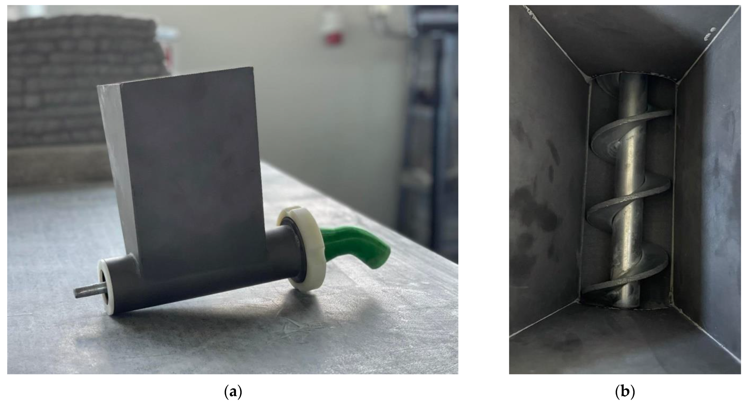
The newly developed methodology for testing the buildability of silicate mixtures for 3D printing consists in extruding the mass through by a screw conveyor through a nozzle printed from PETG with a diameter of 25 mm. The equipment itself is pictured in
Figure 6.
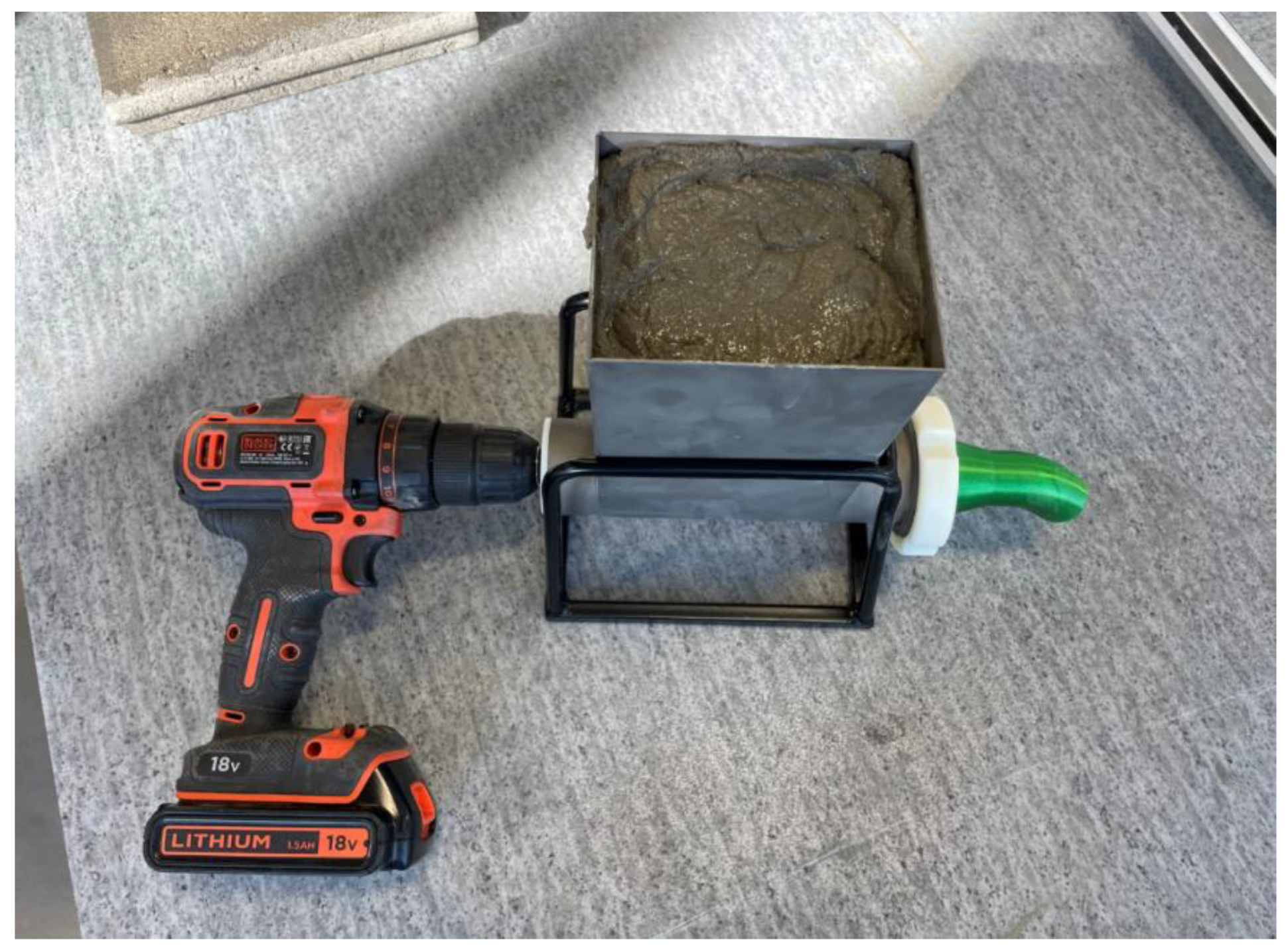
A hopper of the extrusion equipment is filled with tested fresh mixture and the device is powered by a power drill (
Figure 7).
Subsequently, a 40 cm long line is extruded through the entire device onto a solid, moistened surface in layers of the same height (
Figure 8).
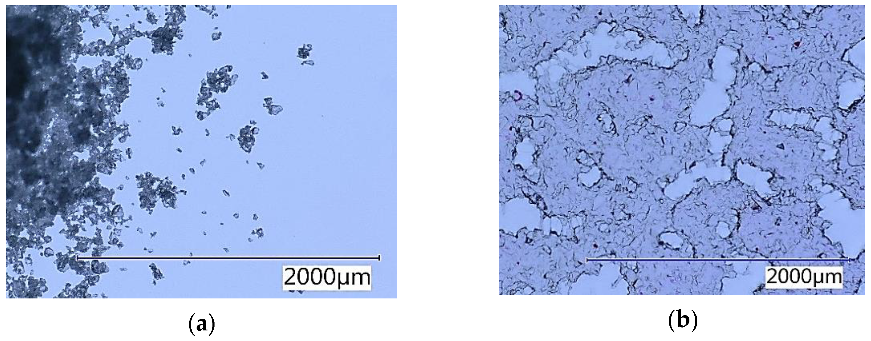
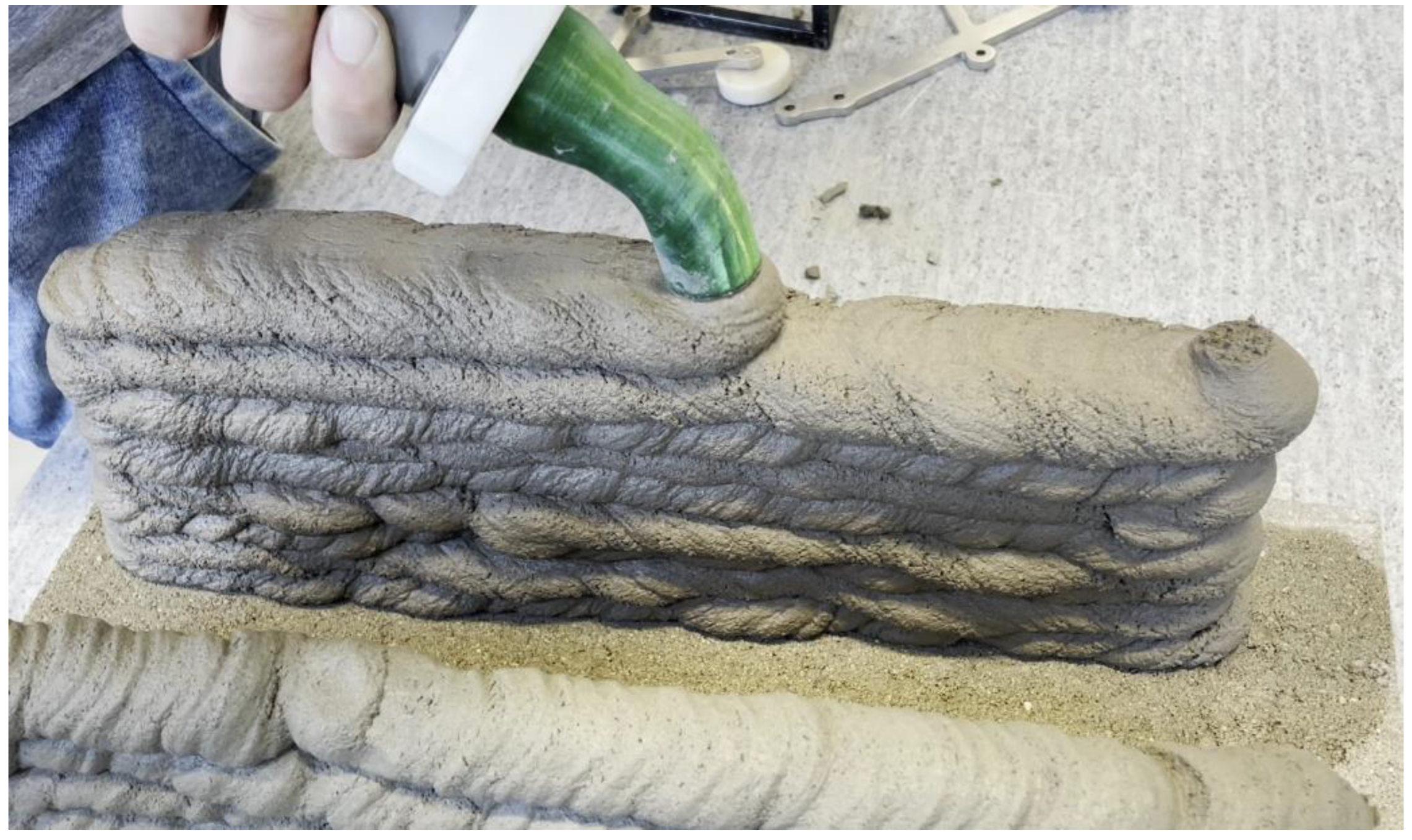
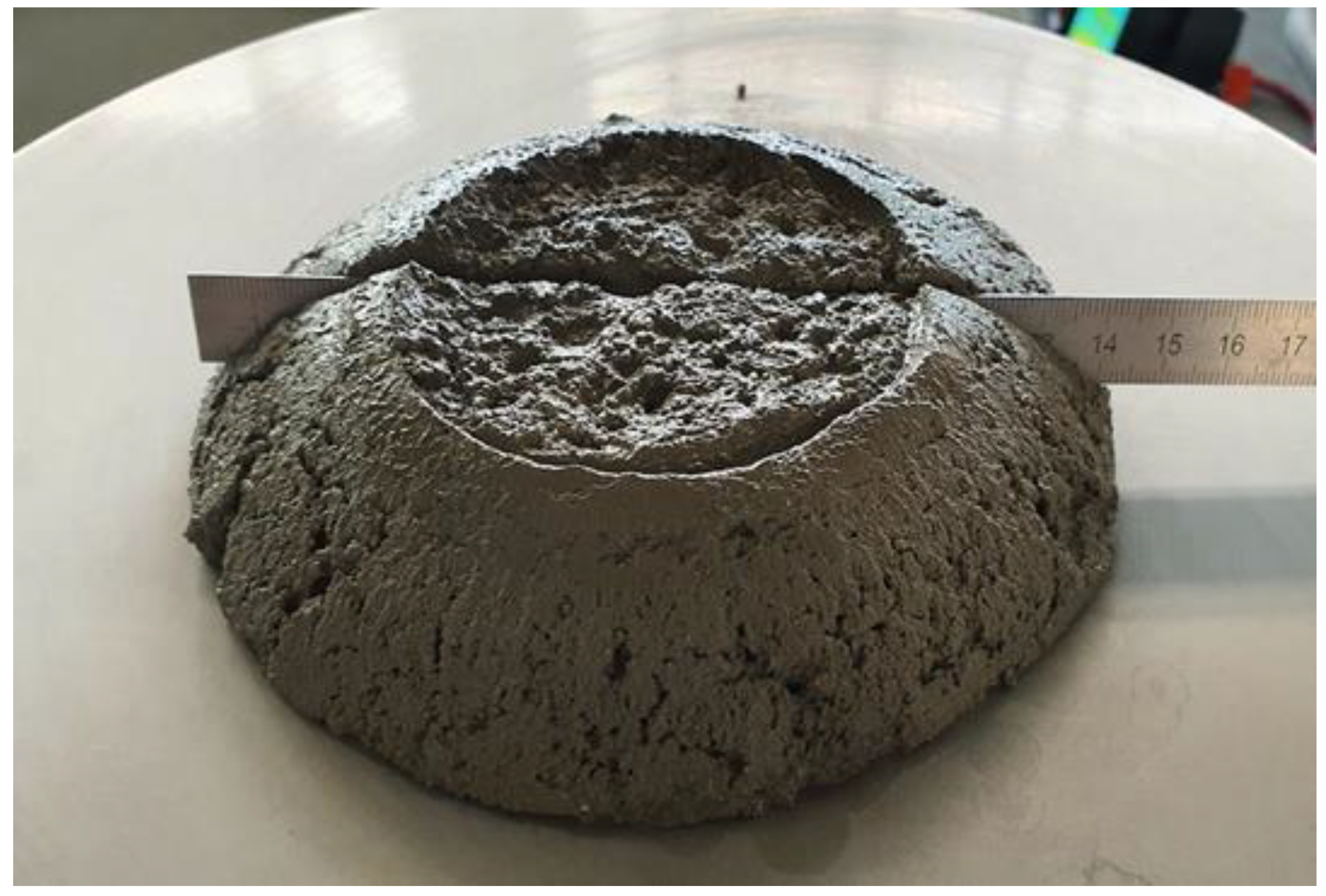
If it is possible to extrude the mixture in ten or more layers without collapsing, the mixture is marked as having met the requirements of the buildability test. Examples of mixtures that failed (
Figure 9) and passed (
Figure 10) the test requirements are shown in the images below.
3.5. X-ray Diffraction Analysis
PanAlytical Empyrean equipment was used for XRD analysis. This method is based on the principle of crystallographic assembly of substances and the interaction of X-ray radiation with particles that form the crystal matrix of the substance. The wavelength of an X-ray beam is similar to the interplanar distances in crystals. Knowing the individual interplanar distances of minerals, it is possible to determine which minerals are present in an unknown sample using XRD.
3.6. Compressive Strength
Compressive strength of all tested mixtures was determined in hardened state 2, 7 and 28 days after production according to the EN 1015-11:2019—Methods of test for mortar for masonry—Part 11: Determination of flexural and compressive strength of hardened mortar standard on the 40 mm × 40 mm × 160 mm beam-shaped test samples.
3.7. Flexural Strength
Flexural strength of all tested mixtures was determined in hardened state 2, 7 and 28 days after production according to the EN 1015-11:2019—Methods of test for mortar for masonry—Part 11: Determination of flexural and compressive strength of hardened mortar standard on the 40 mm × 40 mm × 160 mm beam-shaped test samples.
4. Mixture Proportions
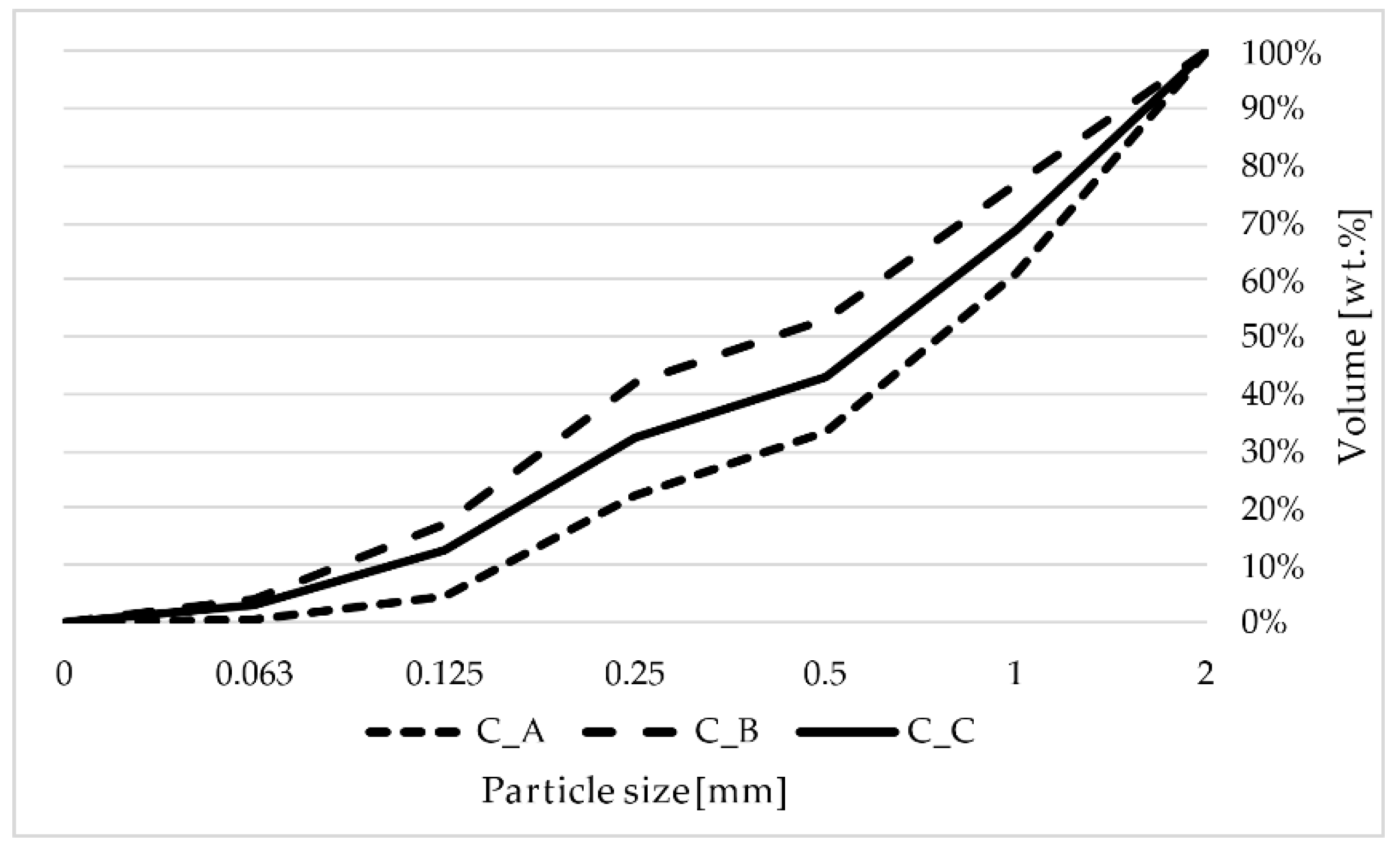
Several aggregate curves in combination with cement as binder were used to determine the optimal mixture for 3D printing. The C_A, C_B and C_C mixture (sieve analysis is shown on
Figure 1). The C_A and C_B mixtures failed during the buildability test, therefore were not tested further and the results are not a part of the paper. The C_C mixture has shown good properties for 3D printing and the mixture proportions are shown in
Table 4.
The amount of SAP was determined according to previous research results of Montanari et al. [
31] and He et al. [
32]; the amount of SAP in the mixtures was calculated using the formula shown in Equation (3):
cf—cement content in the mixture kg/m3,
cs—chemical shrinkage of cement,
αmax—expected maximum degree of hydration, which ranges from 0 to 1,
φSAP,30—absorption of the SAP in pore solution at 30 min of absorption.
The calculated amount of SAP in the mixture is stated in
Table 5.
Mixture proportions used in this study are shown in
Table 5.
5. Results and Discussion
For printing purposes, three filler curves were used, as shown in
Figure 1 and
Table 6. The C_A mixture contained only silica sand of fraction 0.1–2.0 mm. The filler curve (sieve analysis) shows the C_A curve is coarse; therefore, the amount of mixing water is lower to achieve the optimum consistency. The C_B mixture contains, in addition to the 0.1–2.0 mm silica sand, quartz dust. The filler curve is very fine and therefore needs more mixing water to achieve correct consistency. The C_C curve was treated to represent the ideal Fuller filler curve and the properties of such a curve were shown to be very good in terms of 3D printing.
5.1. Consistency
The correct consistency for optimal buildability was tested according to the EN 1015-3 flow table test. The correct consistency is shown in
Figure 11.
When the consistency is lower than 135 mm, the surface of the printed part starts to show tears and initial cracks, which leads to non-uniform printing and can lead to problems with connecting each following layer to the previous one. When the consistency is higher than 160 mm, the printing part can become runny and not hold its shape while printing and can lead to deformities or collapse of the printed structure. Long was studying the workability and consistency of cement-based materials for 3D printing and [
33] added the micro-sized microcellulose in order to fill and reduce the micropores between particles and to reach optimal workability of the mixture. Long found out that the micropores between particles increase the probability of collisions among the particles and have a negative impact on workability. Tao [
33] took similar advantage of cenospheres and used their ability of internal curing. The realized research shows that the SAP makes the fresh mixture less workable and to reach comparable workability it is necessary to add more water. After a few minutes, the SAP absorbs the redundant water and the mixture is much drier than the reference sample. This effect is very important for application to 3D printing. The mixture has to start hardening right after application. From this point of view, SAP is more effective than micro-sized cellulose.
5.2. Volumetric Weight
The volumetric weight was determined on fresh mortar as well as on the hardened mortar after 2, 7 and 28 days of curing. The results are shown in
Table 6.
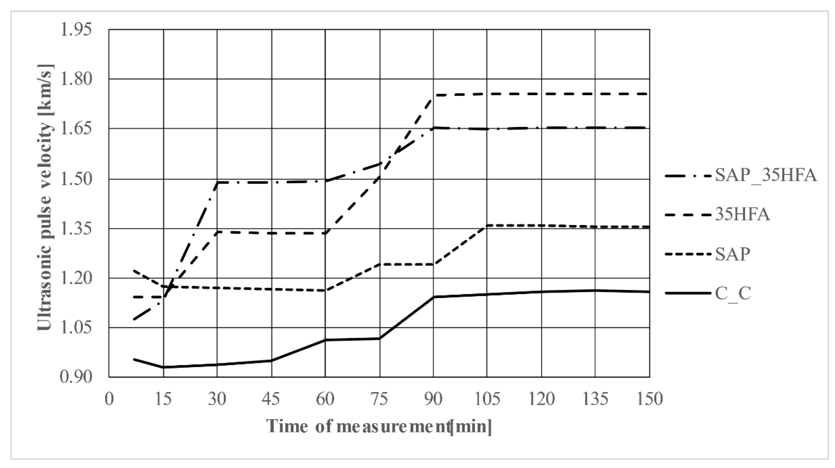
5.3. Ultrasonic Analysis
Acoustic methods (sound waves travelling through a material volume are analyzed for echoes and harmonic features) can be used for evaluation of material structure [
34]. The measurement results are shown in
Figure 12 (ultrasonic pulse velocity) and
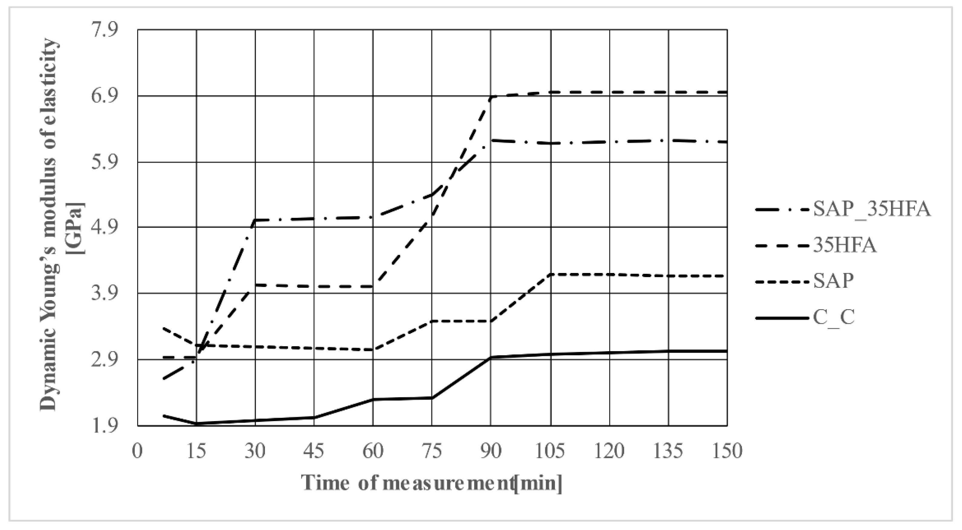
Figure 13 (dynamic Young’s modulus of elasticity).
The course of propagation speed of the ultrasonic pulse or of the dynamic modulus of elasticity over time was different for individual types of mortars, which can be explained by differences in their composition.
As a result of the different composition of mixtures, there is also a different process of their hydration; there is a different formation of hydration products over time and thus also a different formation of its internal structure. This is evident from the results of the method in
Figure 12 and
Figure 13, where subsequent stagnation of the propagation speed of the ultrasonic pulse or dynamic modulus of elasticity can be observed. The propagation speed stopped changing after approximately 90–105 min from mixing. The dynamic Young’s modulus is dependent mainly on the composition of the mixture. In concrete, the Young’s modulus is most dependent on the used aggregate. For this study, the same aggregate was used for every mixture, therefore, the above results are mainly dependent on the used admixture (SAP), substitution of cement by HFA and the amount of mixing water. After a certain period of time, specifically after 45 to 105 min, the mentioned parameters (V, EU) stagnate over time—their differences are minimal up to 1%; this phenomenon can be explained by the fact that after this time the mortar begins to solidify.
In terms of dynamic modulus of elasticity in the initial period of the fresh mortar hydration process, the highest values were achieved for mixtures 35HFA and SAP_35HFA.
Mixture SAP_35HFA contained 35 wt.% substitution of binder by HFA and 0.11 wt.% addition of SAP (relative to the binder), and in Mixture 35HFA, the speed of propagation of the ultrasonic pulse increased the most. This can be explained by the substitution of 35 wt.% of binder by HFA combined with low water to cement ratio.
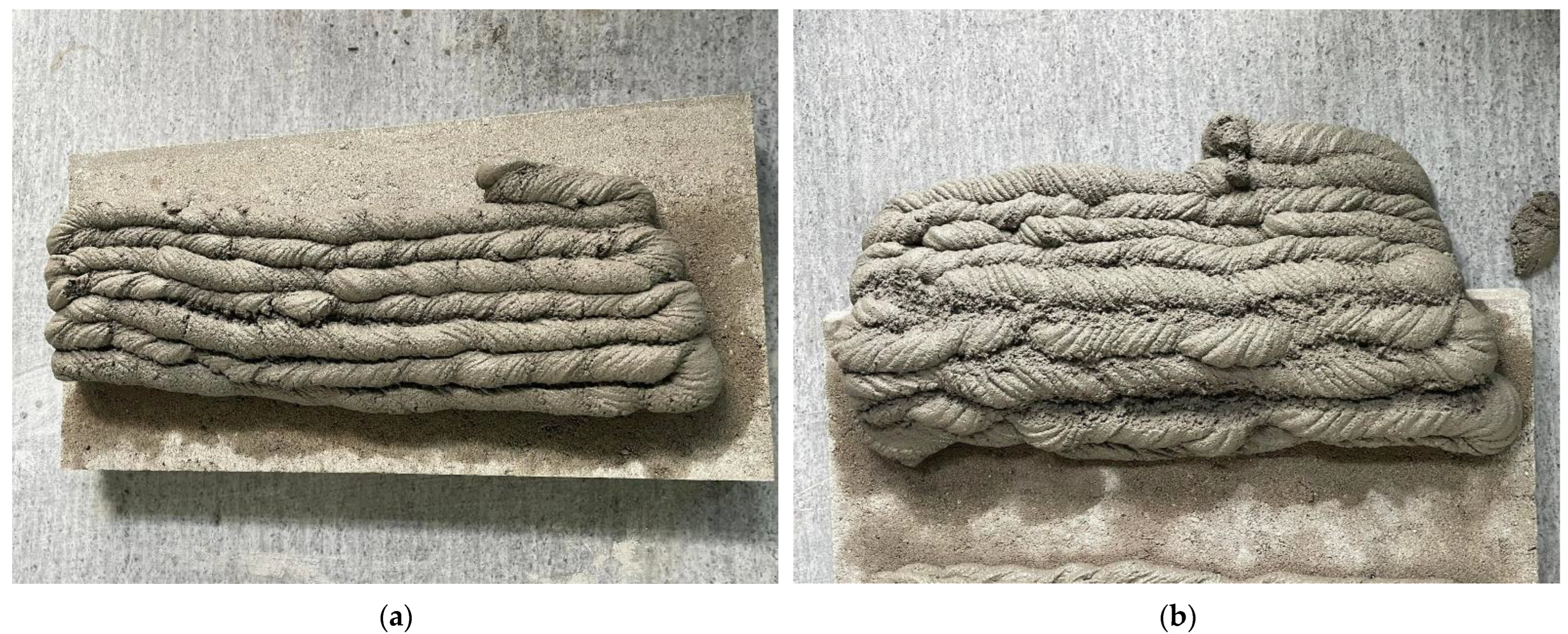
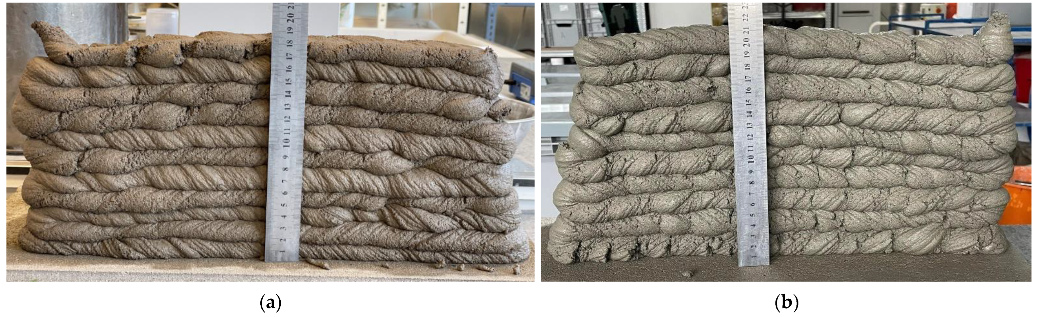
5.4. Buildability
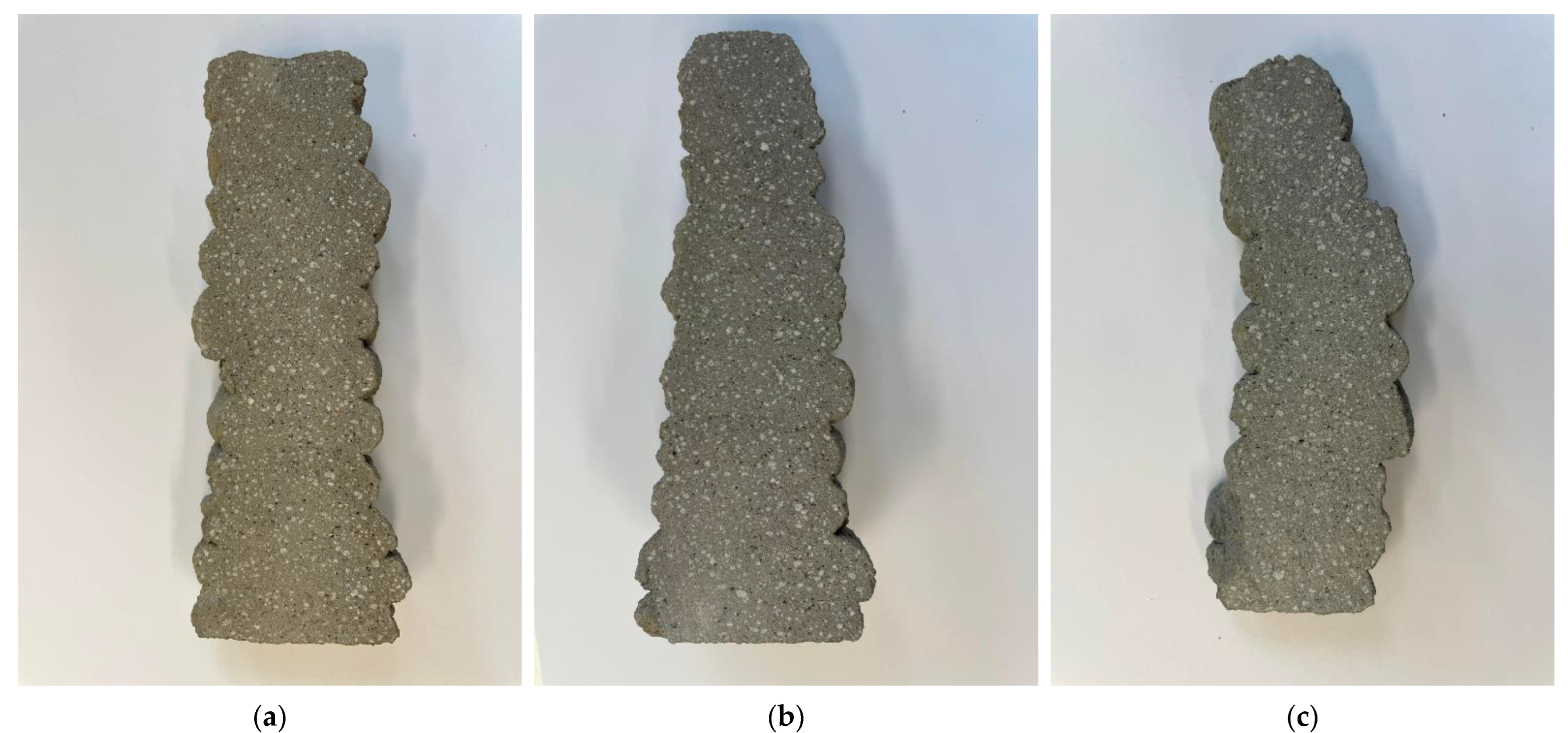
The buildability was tested according to the method stated in
Section 3.4. of this paper. The approximate height of each following layer was 15 mm. The optimal buildability consistency and mixture proportions of SAP_35HFA and SAP are shown in
Figure 13. The mixture C_C could be built, but the stability of structure was not as sufficient as for the other mixtures. As shown in
Figure 14, the following layers are all combined with previous layers without showing any pores or caverns.
The buildability of C_A, C_B and C_C mixtures was tested. The C_A and C_B mixtures contained too coarse or too fine filler curve, which resulted in problems during printing, therefore the C_A and C_B mixtures are not a part of results in this paper. The C_C mixture showed good buildability properties and the therefore was further modified by SAP and HFA. The addition of SAP and/or HFA did result in even better buildability. The mixture 35HFA, containing substitution of 35 wt% of binder, showed smoother surface and better overall printing performance. The addition of SAP resulted in very easily printable material, which started to thicken right after being printed, which resulted in good print. The SAP_35HFA combined properties of both SAP and HFA and resulted in very easily printable material with a smooth surface.
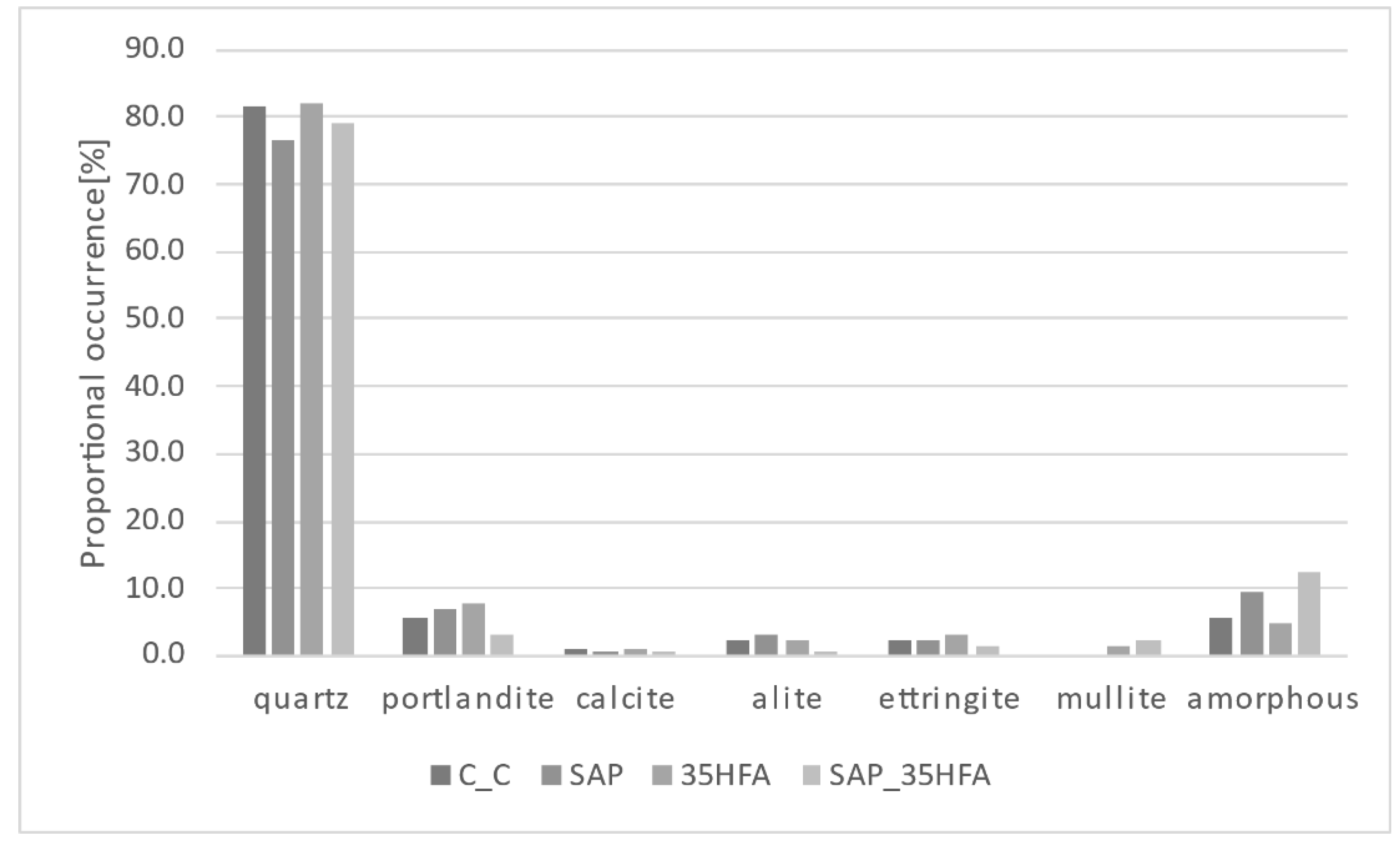
5.5. X-ray Diffraction Analysis
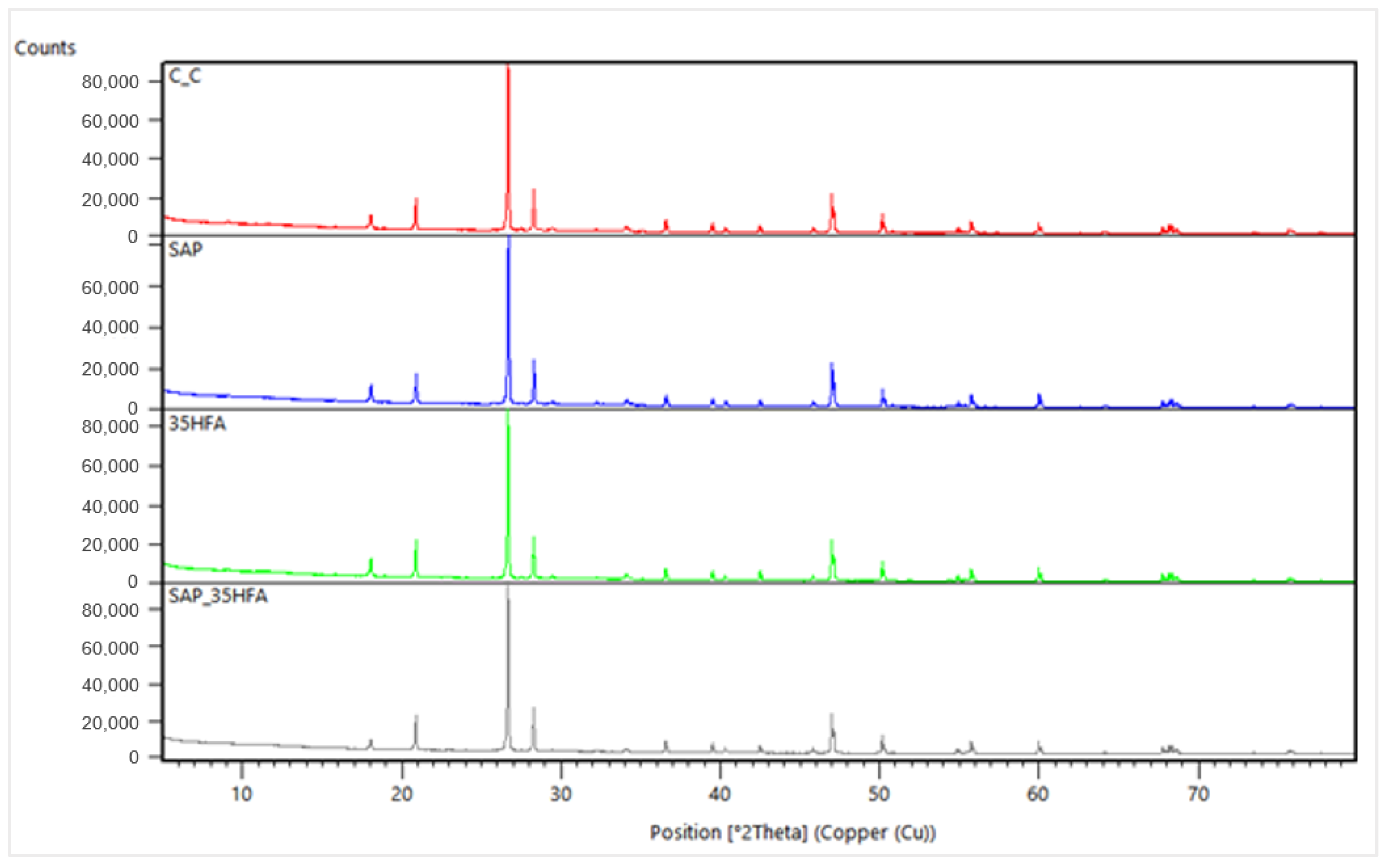
A powder sample surface was irradiated by X-rays and the pattern was recorded in a step-scan mode (
Figure 15).
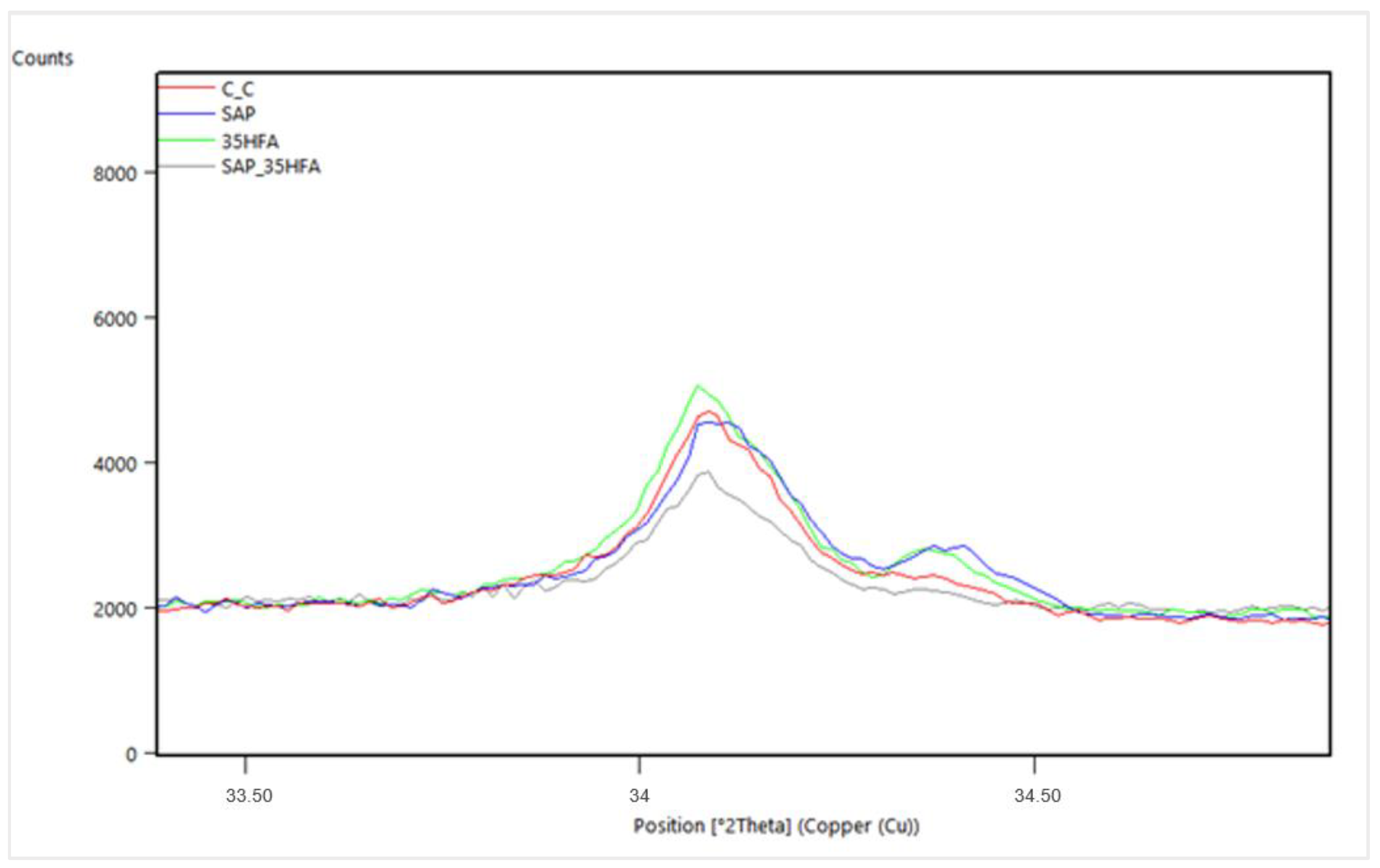
In the samples were identified minerals: quartz, portlandite, calcite, alite, ettringite, and the amorphous phase. In samples with the addition of fly ash, the presence of a low amount of mullite was observed. A detail of the most intensive peak of portlandite for all mixtures is shown in
Figure 16. Liu [
35] detected by XRD analysis in samples of 3D printed concrete anhydrous phases of OPC (alite, belite, tricalcium aluminate, brownmillerite, gypsum, calcite) and CAC (CA, C
12A
7, C
2AS, C
2S, C
2AS).
The refinement of minerals crystal structures was realized by the Rietveld analysis with the percentual occurrence of minerals shown in
Figure 17. According to this analysis, the higher proportion of alite genesis in samples without fly ash addition is observed. Slight decrease of the calcite genesis as a consequence of SAP addition was observed. In samples with content of SAPs, lower presence of quartz and higher occurrence of amorphous phase in comparison with samples without SAP was observed.
The amount of portlandite increased in SAP and 35HFA compared to the C_C mixture. This was probably due to the fact the SAP mixture contained additional water absorbed by the SAP admixture and produces more homogenous porous structure which results in higher rate of hydration than C_C reference mixture without SAP addition. The 35HFA mixture also contains a larger amount of portlandite, due to the fact that the mixture contained a lesser amount of mixing water and the reaction between cement and HFA had not taken place after 28 days of curing. On the other hand, the SAP_35HFA mixture contained only a small amount of portlandite and a large amount of amorphous phase due to the larger amount of water, SAP addition and further reaction between cement hydration products and HFA. In mixtures containing HFA, the 35HFA and SAP_35HFA, the mullite can be found. The larger amount of mullite can be found in the SAP_35HFA mixture, probably due to the facts stated above. The amount of alite is also decreased in the SAP_35HFA mixture, due to the facts stated above and the reaction between clinker minerals and fly ash in presence of large amounts of excess moisture and very good curing conditions.
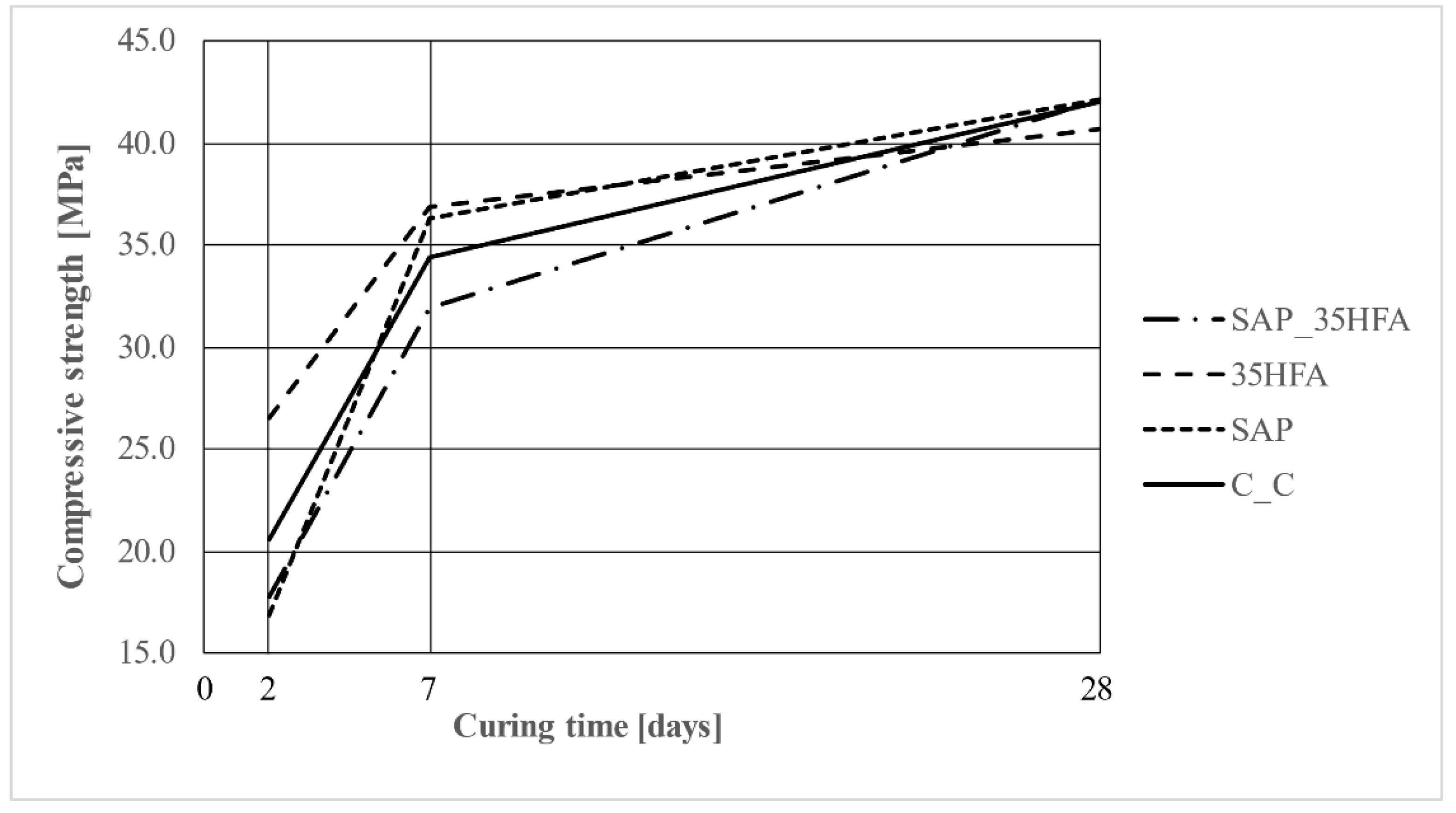
5.6. Compressive Strength
The compressive strength of test samples was determined after 2, 7 and 28 days of curing. The highest early age compressive strength was achieved for the 35HFA mixture and the highest compressive strength after 28 was the exact for the SAP_35HFA and the SAP mixture. The strengths are shown in
Figure 18.
The early compressive strength (2 days) was the highest for 35HFA and lowest for the SAP mixture. The early compressive strengths correspond with the amount of mixing water and the addition of the SAP admixture. The mixtures with the highest amount of mixing water and with the addition of SAP showed a lower compressive strength than the reference. Meanwhile Liu [
35], in his research of a 3D-printed rubberized concrete mixture, found that 28-day compressive cubic strengths reached compressive strengths of about 30 MPa; in this research he obtained 28-day compressive strengths over 40 MPa even by replacement of 35% of the binder by fly ash. The compressive strength after 28 days was similar for all mixtures. The 35HFA mixture showed marginally lower compressive strength. The mixtures containing SAP showed lowest compressive strength, which corresponds with findings of other papers [
36,
37] where carbon nanotubes were used. The early flexural and compressive strengths were decreased due to the hydrophilic nature of carbon nanotubes and excess of mixing water in the mixture, which most certainly leads to delaying of the hydration process. This probably works very similarly for the mixtures containing SAP admixture. Both compressive and flexural strengths increased rapidly during the further hydration (for the mixtures containing SAP after 7 and 28 days of curing).
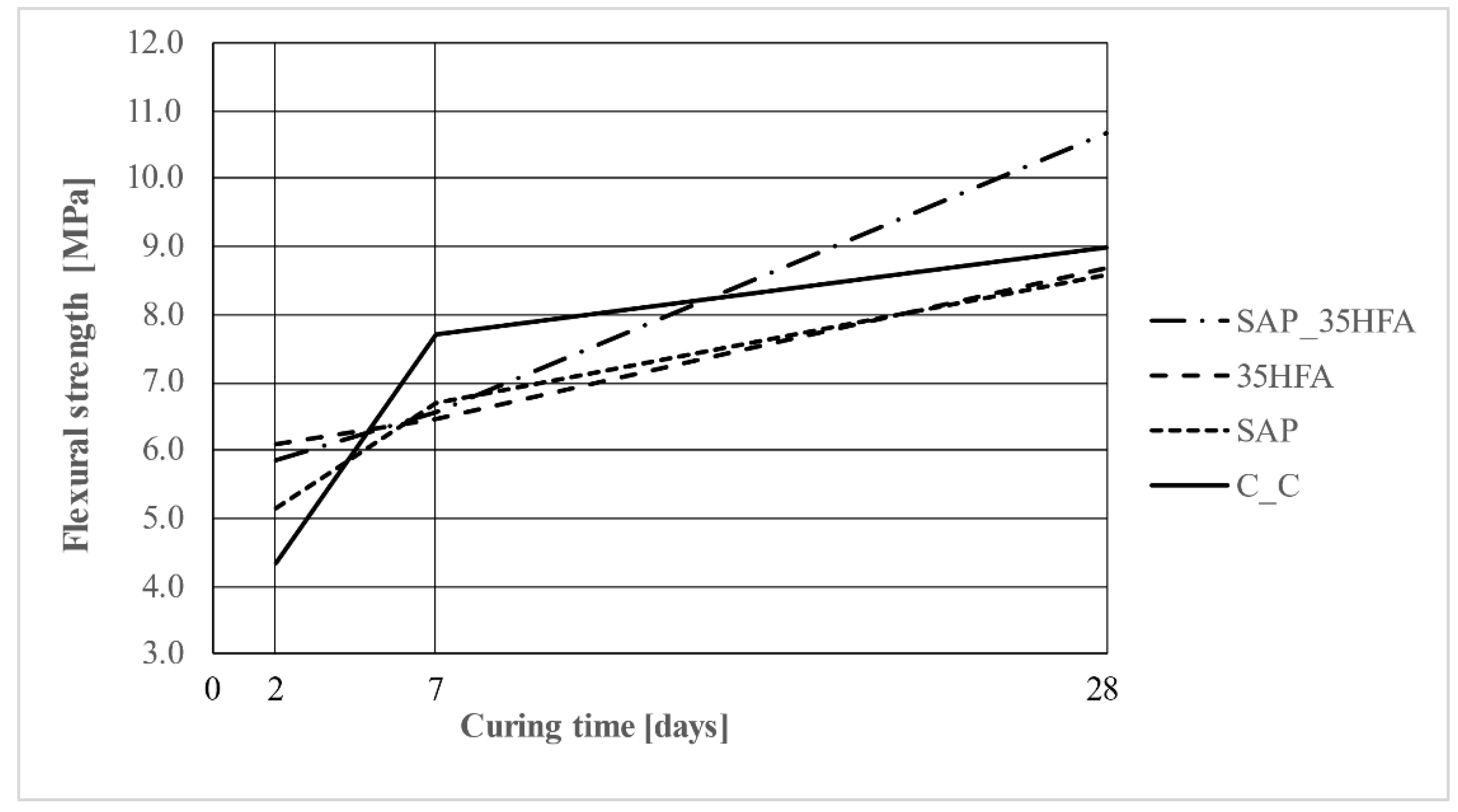
5.7. Flexural Strength
The flexural strength of test samples was determined after 2, 7 and 28 days of curing. The highest flexural strength was achieved for the SAP_35HFA mixture. This result was achieved by a combination of effects of adding both SAP and HFA to the mixture. The strengths are shown in
Figure 19.
The early flexural strength shows different results to the compressive strength. The mixtures containing SAP admixture showed higher early-age flexural strength than the reference samples. The flexural strength after 28 days was the highest for the SAP_35HFA mixture. This is due to the addition of SAP and HFA, which can both lead to an increase in flexural strength. In comparison with this finding, Xu’s [
38] mixtures of 3D printed concrete with used fly ash, without SAP addition, achieved a flexural strength decrease. He found out that as the FA concentration increases the strength rapidly diminishes. In Xu’s research, the flexural strength decreased about 30% by the addition of 40% fly ash. The results of the research show that the addition of SAP has a positive impact on the flexural strength in the middle stage of hydration in the case of partial replacement of cement binder by fly ash.
6. Conclusions
In this research, the interaction of CEM II binder with fly ash (HFA) and superabsorbent polymers (SAPs) in mixtures for concrete 3D printing was investigated. The influence of HFA and/or SAP on the optimal consistency, buildability, results of XRD analysis (crystalline composition) and mechanical properties (i.e., compressive strength, flexural strength, dynamic Young’s modulus) were evaluated. The research analysis revealed the HFA and SAP contribute to the printability, buildability and quality of the surface of 3D printed elements. The following conclusions were made based on the experimental results and observations:
The CEM II binder in combination with SAP and 35 wt.% substitution of cement by HFA can lead to a decrease in the needed amount of Portland clinker by up to 50% (CEM II B-M contains 65–79 w.t% of Portland clinker) while achieving suitable physical–mechanical properties and producing good quality prints. This can be used to produce more environmentally and economically friendly materials.
The SAP can be used to increase the long-term flexural strength after less than 28 days of curing (which supports the findings of C.J. Adams et al. [
39]) and to improve the overall parameters due to the self-curing ability of SAP admixture.
The addition of SAP can lead to a decrease in early-age physical–mechanical parameters due to the excess of mixing water in the mixture successfully delaying the hydration (the difference between reference mixture and mixtures containing SAP became less marginal after 7 to 28 days of curing).
Both the SAP and HFA can be used to print 3D structures with smoother surface and less cracks and defects in mortar while preserving the physical–mechanical parameters of 3D printed elements.
Ultrasonic analysis can be used to sufficiently measure dynamic Young’s modulus of elasticity in a fresh state to visualize the beginning of the hardening process of concrete.
In general, the concrete mixture made from cementitious binder in combination with a smooth aggregate distribution curve, low w/c ratio, modern PCE admixtures and adequate consistency is enough to produce a mixture suitable for concrete 3D printing. The HFA and/or SAP admixture can be used to increase the quality of produced 3D printed elements and to increase the physical–mechanical parameters (mainly flexural strength).


