Article

Experimental Study on Self-Compacting Concrete-Filled Thin-Walled Steel Tube Columns

1
School of Civil and Architecture Engineering, Hunan University of Arts and Science, Changde 415000, China
2
State Key Laboratory of Performance Monitoring and Protecting of Rail Transit Infrastructure, East China Jiaotong University, Nanchang 330013, China
3
School of Civil Engineering and Architecture, East China Jiaotong University, Nanchang 330013, China
4
School of Civil and Architecture Engineering, Liaoning University of Technology, Jinzhou 121000, China
5
College of Water Resources and Architectural Engineering, Northwest A&F University, Xianyang 712100, China
*
Authors to whom correspondence should be addressed.
Buildings 2022, 12(12), 2134; https://doi.org/10.3390/buildings12122134
Submission received: 25 September 2022 / Revised: 31 October 2022 / Accepted: 16 November 2022 / Published: 5 December 2022
(This article belongs to the Section Building Materials, and Repair & Renovation)

Abstract

:
Concrete-filled steel tubes present excellent structural and constructional performances because they ideally combine the advantage of concrete and steel tube. Thus, they are widely used in civil infrastructures. However, they inevitably suffer from either hard compacting or high costs. Thus, convenient and rapid construction for compacting concrete and cost saving are the urgent challenges for concrete-filled steel tubes. Therefore, this study investigates filling a thin-walled steel tube with self-compacting concrete to solve the challenges presented by traditional concrete-filled steel tube columns, such as poor compacting performance and high costs. This experimental study tests self-compacting concrete-filled thin-walled steel tube (SCCFTST) columns under concentric compression from loading to failure. Effects of wall thickness of the thin-walled steel tube on the failure modes, load-deformation behaviors, and the ultimate loads of the SCCFTST columns are comprehensively investigated. The ultimate loads between experiments and their calculated values in terms of design codes are also compared. The results suggest that buckling on thin-walled steel tube surface is the typical failure mode. The amount of local buckling increases with decreasing wall thickness, and the decreasing rate of the load-deformation curves in the descending branch decreases by increasing the wall thickness, as well as the ultimate load increasing with increases wall thickness. The ACI and CECS are the most conservative and accurate design codes, respectively, for predicting the ultimate load. Therefore, the SCCFTST columns can be used as structural components in civil infrastructures and their peak loads can be calculated using design codes for conventional concrete-filled steel tube columns. However, modification measures must be taken while predicting the ultimate loads of the SCCFTST columns by design codes. The experimental results of this paper can contribute towards the application of SCCFTST columns in practice.

1. Introduction

Concrete-filled steel tubes present significant advantages in both design and construction, and have been extensively used in civil infrastructures, such as buildings, bridges, tunnels, and offshore structures [1,2,3,4,5,6]. Firstly, the concrete core can be confined by the steel tubes which also can be used as a permanent formwork. On the contrary, the concrete core can delay buckling of the steel tube. Therefore, the steel tube is buckled outwards due to the concrete core [7,8]. Compared with reinforced concrete and steel tube, the concrete-filled steel tube presents many advantages, for example high ultimate load, favorable ductility, better seismic resistance [9,10,11,12,13], energy absorption [14], and damping resistance [15]. Therefore, the concrete-filled steel tube not only possesses excellent properties, but also allows rapid construction [16,17,18,19].
Concrete-filled steel tubes are always application in concrete columns. Extensive experimental investigations on concrete-filled steel tube columns have been carried out in recent decades regarding the performances of the columns under axial and eccentric loadings. The primary parameters have included cross section shape, material strength, loading types, and slenderness [1,2,20,21,22,23,24,25,26,27]. The performances of the concrete-filled steel tube columns are affected by the main parameters, including their geometrical parameters, such as the slenderness [22,26,28,29], ratios of diameter to wall thickness [23,24,28,30,31], ratios of width to wall thickness [7,29,32,33], initial geometry [7,34,35,36], mechanical properties, the terminal conditions and loading, and constraint of concrete by steel tube [22,23,28,32,34]. The research results indicate that the ultimate loads of the concrete-filled steel tube columns decrease by increasing both the length of columns as well as the ratios of load eccentricity [7,22,26,28]. The bonding strength between concrete and steel tube of the lightweight concrete-filled steel tube is reduced by up to 21% after 200 °C [25]. The compressive yielding and local buckling of steel tubes and crushing of concrete are the primary failure modes of the concrete-filled steel tube columns. However, failure modes of the longer columns exhibit instability, with cracking and crushing of concrete and partial compressive yielding of the steel tube. The concrete-filled steel tube columns present favorable ductility and tenacity under cycling loads. Therefore, they are appropriate applications in constructions subject to dynamic loads, for instance seismic waves and wind loads [37]. However, performances of steel tubes and concrete deteriorate under high-temperatures. The decreasing rates of the ultimate loads of concrete-filled steel tube after 200 °C, 600 °C, and 800 °C are 12.3%, 35.55%, and 75.83%, respectively [38,39].
In previous research, the wall thickness of steel tubes is always more than 3 mm. However, for the progress in high performances of steel tubes with thin wall thickness, they are popular applied in civil infrastructures. On the one hand, thin-walled steel tubes can provide sufficient confinement on concrete core. Additionally, the steel ratios of the concrete-filled steel tube columns can be reduced; thus, the cost will also be reduced [29,32].
However, it is a challenge to fill gaps and guarantee compacting of internal concrete during the pouring process of the concrete-filled steel tube columns. Fortunately, self-compacting concrete can flow across barriers and fill in space within corners between steel and molds under its weight need not vibration during the concrete pouring process. It is therefore a good choice to solve these problems. Self-compacting concrete is characterized as having good flowability and workability, as well as reducing consolidation noise, saving labor, and enhancing the durability of concrete structures [40,41].
Self-compacting concrete has been extensively applied in concrete structures of civil infrastructures, but investigate on performances of self-compacting concrete-filled thin-walled steel tubes (SCCFTST) columns from experiments is limited. Han and Yao studied the influence of concrete compaction methods on the ultimate loads of concrete-filled steel tube columns. Concrete compaction methods included well-compacting with vibration and self-compacting without vibration. They pointed out the ultimate loads of the concrete-filled steel tube columns with concrete compacted by vibration are 8.3–14% higher than those compacted without vibration [42]. Wang et al. determined that the concrete-filled steel tube columns display serious buckling and rupture on steel tube surface. The concrete is crushed nearby the rupture of steel tubes. In addition, the numbers of buckling are increased with increasing of diameter to wall thickness ratios. They also proved that the buckling is approached to the ends of columns [43].
Application of the SCCFTST columns in civil infrastructures is limited because of comprehensive on their mechanical performances is not enough. Therefore, this study investigates filling thin-walled steel tubes with self-compacting concrete to solve the challenges posed by traditional concrete-filled steel tube columns, such as poor compacting performance and high costs. Experiment on performances of the SCCFTST columns subject to axial compression from loading to failure is conducted. The influence of wall thickness on failure modes characteristics, load-deformation performances, and the ultimate loads of the SCCFTST columns are comprehensively investigated. The ultimate loads between experiments and calculated values by design codes are also compared. In this study, wall thickness of the thin-walled steel tubes contains 1.2 and 3 mm, and the ratio of length to diameter of thin-walled steel tubes is 3.0.

2. Experimental Programs

2.1. Material Properties

The external diameter of thin-walled steel tubes is 140 mm, and their height is 420 mm. Most commonly application in engineering of wall thickness 1.2 mm and 3 mm is designed. The mechanical performances of the thin-walled steel tubes obtained from tension test according to the metallic materials tensile testing method [44]. Mechanical performances and characteristics of the thin-walled steel tubes are listed in Table 1. It can be seen from Table 1 that the parameters D, t, and L represent external diameter, wall thickness, and height of thin-walled steel tubes, respectively. Elasticity modulus of steel tube with dimensions of 140 mm × 1.2 mm × 420 mm is 1.8 × 10⁵ MPa, as shown in Table 1, which is smaller than that of the normal value due to the wall thickness 1.2 mm is smaller than that of the conventional wall thickness of steel tube always more than 3 mm. The mix proportion and mechanical performances of self-compacting concrete are shown in Table 2. fcu, fck, and Ec represent compressive strength of cubic and prism, and modulus of elasticity of concrete, respectively. The mechanical performances of the self-compacting concrete are obtained in accordance with standard methods [45].

2.2. Specimens Design and Preparation

Four SCCFTST columns are designed and prepared. The numbers of four specimens are N-T1-1, N-T1-2, N-T2-1, and N-T2-2, respectively. The letter N represents the type of concrete. T1 and T2 represent the wall thicknesses 1.2 mm and 3 mm of the thin-walled steel tubes, respectively. The last number represents the specimen number.
Two square steel plates with side length of 180 mm and thickness of 10 mm are welded on top and end of the thin-walled steel tube. The top and end surface of the thin-walled steel tube is polished smoothly before welding. One of the endplates is used for formwork while casting the concrete, and the other endplate is welded one day before the experimental test. The center of the thin-walled steel tubes and the top and end steel plates are ensured to be in the same vertical line. The columns are cured in a curing chamber after casting. Six prisms of 150 mm × 150 mm × 300 mm and three cubes with side length of 150 mm are cast and cured at the same conditions of the SCCFTST columns.
After 28 d curing, longitudinal shrinkage of about 1–2 mm in length is generated on top of the SCCFTST columns. The shrinkage area of the SCCFTST columns is filled cement paste with high strength before testing. Then, the other steel plate is welded on top of the thin-walled steel tube.

2.3. Test Programs

Eight strain gauges arranged at both longitudinal and lateral directions to test strains on surface of the SCCFTST columns. Additionally, their displacements are measured by two linear variable displacement transducers which arranged along height of the SCCFTST columns. Data acquisition system is used to collect test data. The typical loading arrangements are shown in Figure 1.
The axial compressive loading is applied on the SCCFTST columns using a universal testing machine. In order to eliminate nonuniform results during the loading process, preloading is applied before the actual test. Both loading rates at the preliminary loading stage and actual loading stage are set as 1 kN/min and 0.5 mm/min, respectively. The load amplitude of preloading is set as 10 kN and three circles of loading-unloading are applied to the columns to adjust the location of the columns according to the strain gauges and displacements, and to make sure the columns are located in the center of the loading platform. Each interval of the applied load is set as one tenth of peak load calculated by theory formulas. The load interval is decreased to one fifteenth of the peak load when loading to 70% of the peak load. Each level of the applied load maintains 3 min. The loading rate is slowly and continuously when loading to peak load. The test process is continued until the load lower than 60% of the peak load. The experimental test time of one specimen from loading to finish lasted about 2 h. Photographs of the loading process are shown in Figure 1.

3. Results and Discussions

3.1. Load-Deformation Characteristics

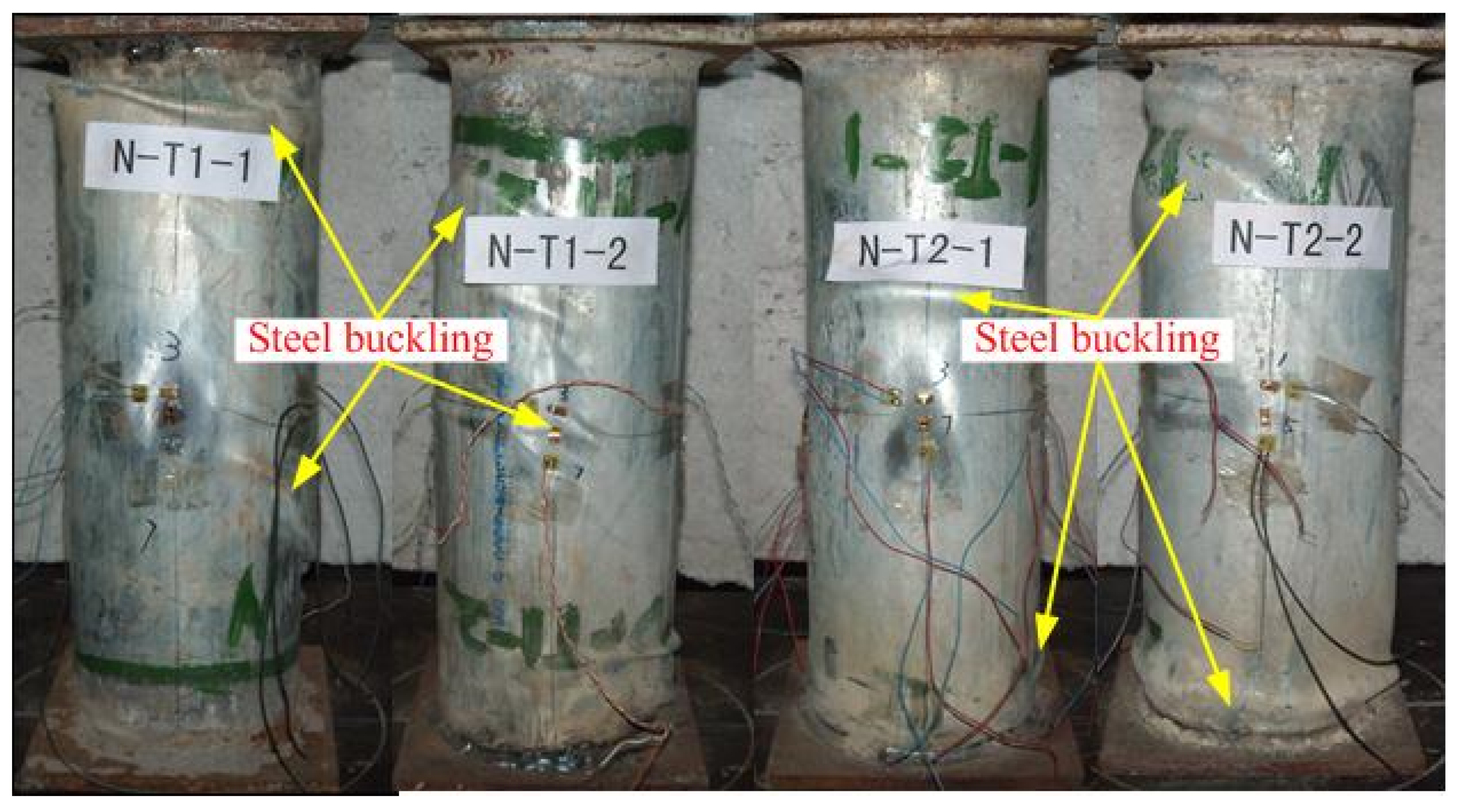
As shown in Figure 1, the whole test procedure is controlled. Figure 2 shows failure mode characteristics of the SCCFTST columns. Thin-walled steel tubes of the SCCFTST columns are buckled outward. Additionally, the thin-walled steel tubes are ruptured as well as the concrete nearby the ruptures almost has been crushed. Buckling is generated on different locations with different thickness of the thin-walled steel tubes. Buckling is distributed in the mid and end of the SCCFTST columns with two types of wall thicknesses 1.2 and 3 mm, respectively.
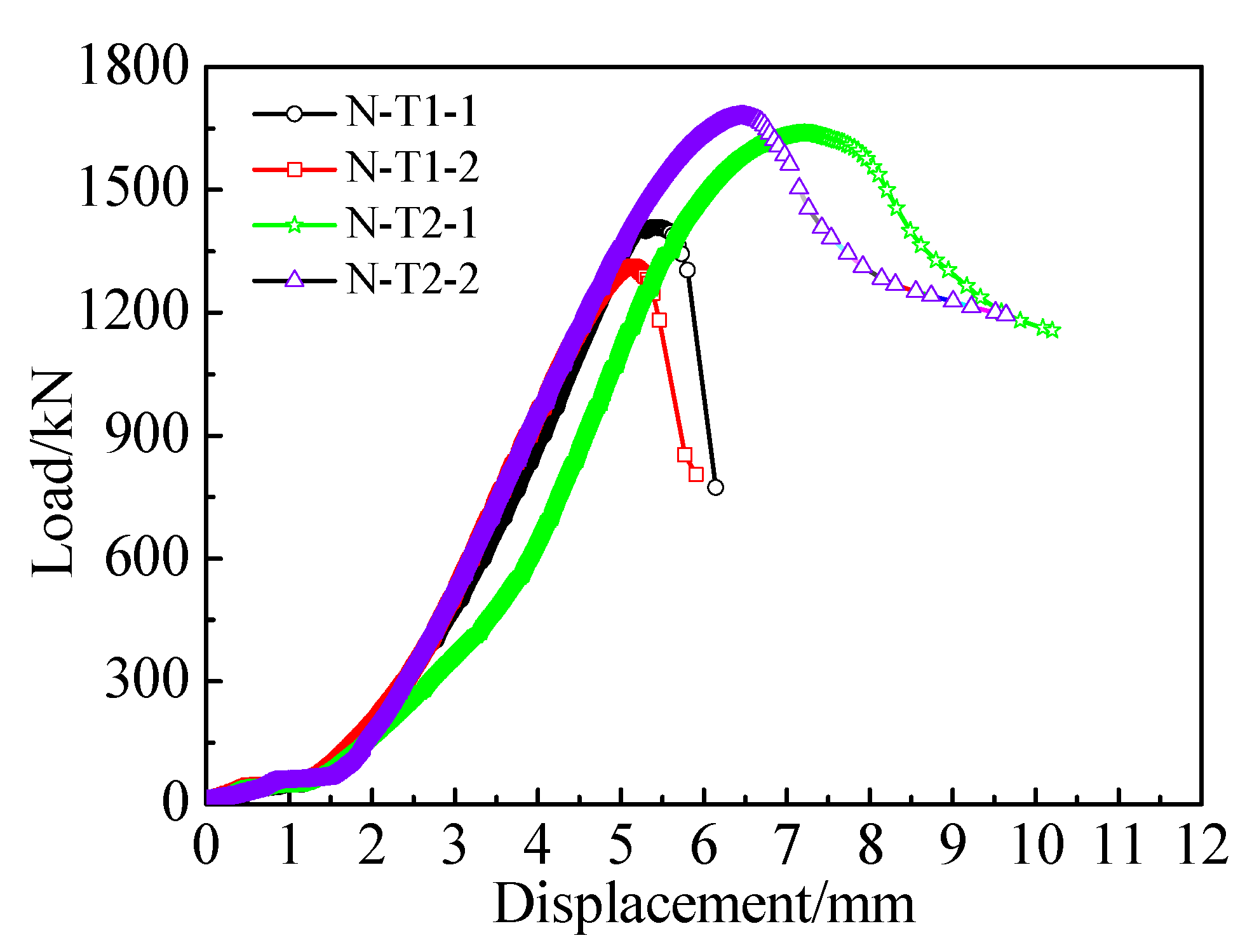
Figure 3 presents the relationships between load and displacement. The displacement is increasing faster than load until loading reaches 50 kN. The reason is that the test machine needed to adjust itself at the beginning of the experiment. The displacement is linearity with load until loading to 70% of the ultimate load. The relationships between load and displacement are nonlinearly from 70% of the ultimate load to failure. Displacements under peak loads of the SCCFTST columns are increased with increasing wall thickness. The descending branch of the load-displacement curves becomes gently with increasing wall thickness of the thin-walled steel tubes. This is because the concrete restraint by the thin-walled steel tube is the crucial effect, which is decreased with increasing confinement. Additionally, the restraint effect of concrete by the thin-walled steel tube is increased with increasing wall thickness of thin-walled steel tube. Thus, the decreasing rate of the load-displacement curves in the descending branch decreases with increasing wall thickness of thin-walled steel tube. Additionally, buckling outward (referred to the buckling generated on regional surfaces outside on steel tubes) on surface of thin-walled steel tubes is not generated before the ultimate load. The amount of outward local buckling increases with increasing wall thickness and ratios of D to t of the thin-walled steel tubes. It can be seen from Table 3 that the ultimate loads are increased with the increase of the wall thickness.
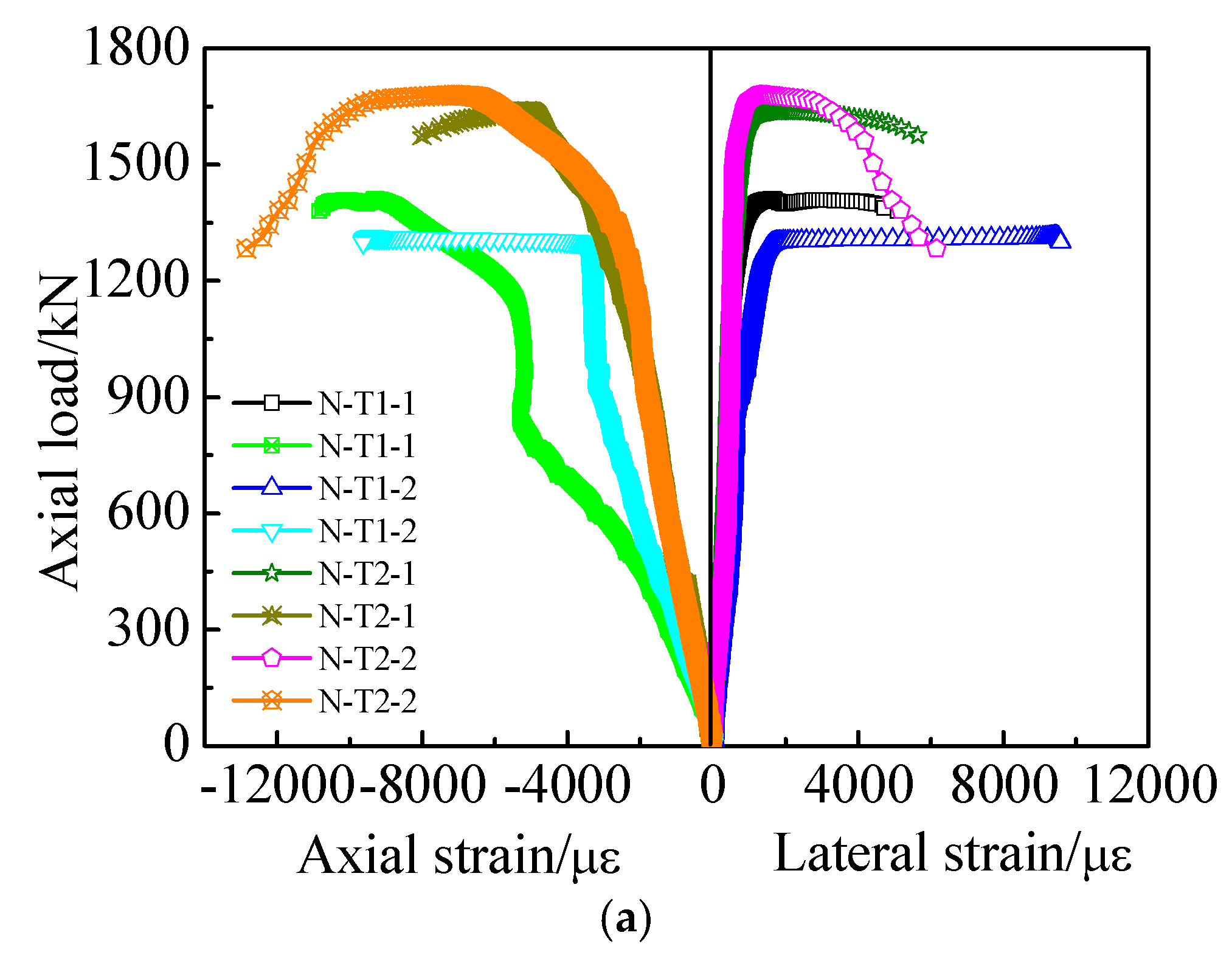
Relationships between load and axial/lateral strains present in Figure 4. Load-strain curves on concrete-filled steel tube columns from loading to failure are an important approach to explain their loading process [46,47,48]. As shown in Figure 4 that the axial strain is nearly linearity to load before 60% of the ultimate load. After that, the curves are nonlinear. The axial strain under the ultimate load almost increases with increasing wall thickness. In addition, the lateral strain is nearly linearity to load before 70% of the peak load, and then, the curves are nonlinear. The lateral strain under the ultimate load is almost similar to each other with different wall thickness.

3.2. Formulas in Different Design Codes on the Ultimate Load

Comparison on ultimate loads from experiments (Nue) and theoretical (Nuc) with different design codes is conducted. The calculation formulas are from nine different design codes, such as DL/T [49], CECS [50], DBJ [51], JCJ [52], ACI [53], AIJ [54], EC4 [55], AISC [56], and BS [57].
The calculation formulas for the ultimate load according to DL/T are provided by Equations (1)–(5). Equation (2) is used to describe the concrete strength improvement by constraint of steel tube.
N u = A s c f s c
f s c = ( 1.212 + B 1 × ξ 0 + C 1 × ξ 0 2 ) f c
ξ 0 = A s f A c f c
B 1 = 0.1759 f y / 235 + 0.974
C 1 = 0.1038 f c k / 20 + 0.0309
where A s c is the total cross-sectional area.
The formulas for the ultimate load put forward by CECS are given by Equations (6)–(8).
N u = ϕ l ϕ e N 0
N 0 = f c A c ( 1 + θ + θ )
θ = f s A s / ( f c A c )
where A c , ϕ l , and ϕ e are concrete cross-sectional area, reduction factor on slenderness, and reduction factor on eccentricity, respectively.
The calculation formulas for the ultimate load according to DBJ can be evaluated as shown by Equations (9) and (10).
N u = f s c A s c
f s c = ( 1.14 + 1.02 ξ 0 ) f c
The formulas for the ultimate load put forward by JCJ are expressed as shown in Equation (11).
N ϕ ( f s A s + K 1 f c A c )
where ϕ , A s , and K 1 are stability coefficient, steel tube cross-sectional area, and increased coefficient of concrete, respectively.
Formulas on the ultimate load from ACI are provided by Equation (12).
N u = 0.85 ϕ ( A s f y + 0.85 f c A c )
The calculation formulas for the ultimate load from JCJ are provided by Equations (13) and (14).
N u = 1.27 A s F + 0.85 f c A c
F = min ( f y , 0.7 f u )
The calculation formulas for the ultimate load according to EC4 are provided by Equation (15).
N u = f y γ s A s + f c γ c A c
where γ s and γ c are partial factors of steel tube and concrete, respectively.
The formulas for the ultimate load by AISC are expressed by Equations (16)–(18).
N u = F c r A s
F c r = ( 0.658 λ c 2 ) F m y                     ( λ c 1.5 )
F c r = ( 0.877 / λ c 2 ) F m y             ( λ c > 1.5 )
where λ c is the ratio of relative slenderness.
The calculation formulas for the ultimate load from BS are provided by Equations (19)–(23).
N u = A s f y r / γ s + 0.675 A c f c c / γ c
f y r = C 2 f y
C 2 = 0.76 + 0.0096 ( L / D )
f c c = f c u + f y C 1 t D
C 1 = 0.0129 ( L / D ) 2 0.7055 ( L / D ) + 9.5275

3.3. Comparison on the Ultimate Loads between Experiments and Theoretical Values

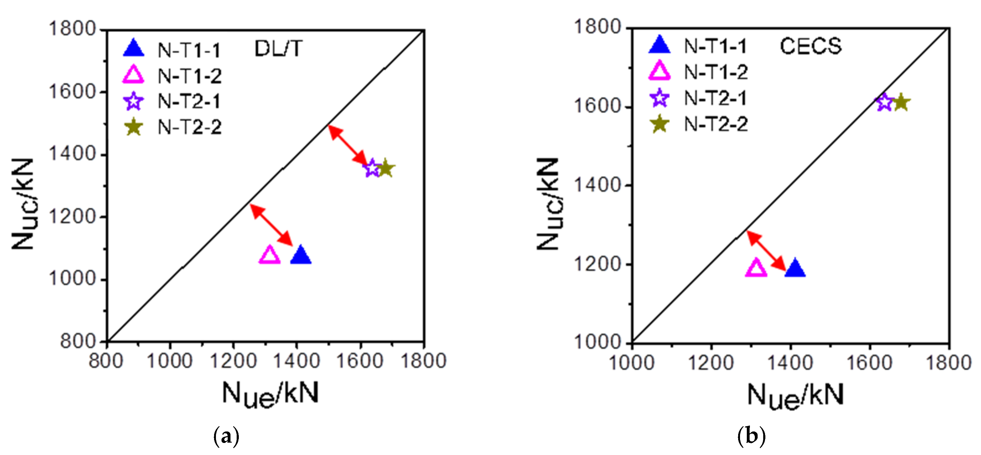
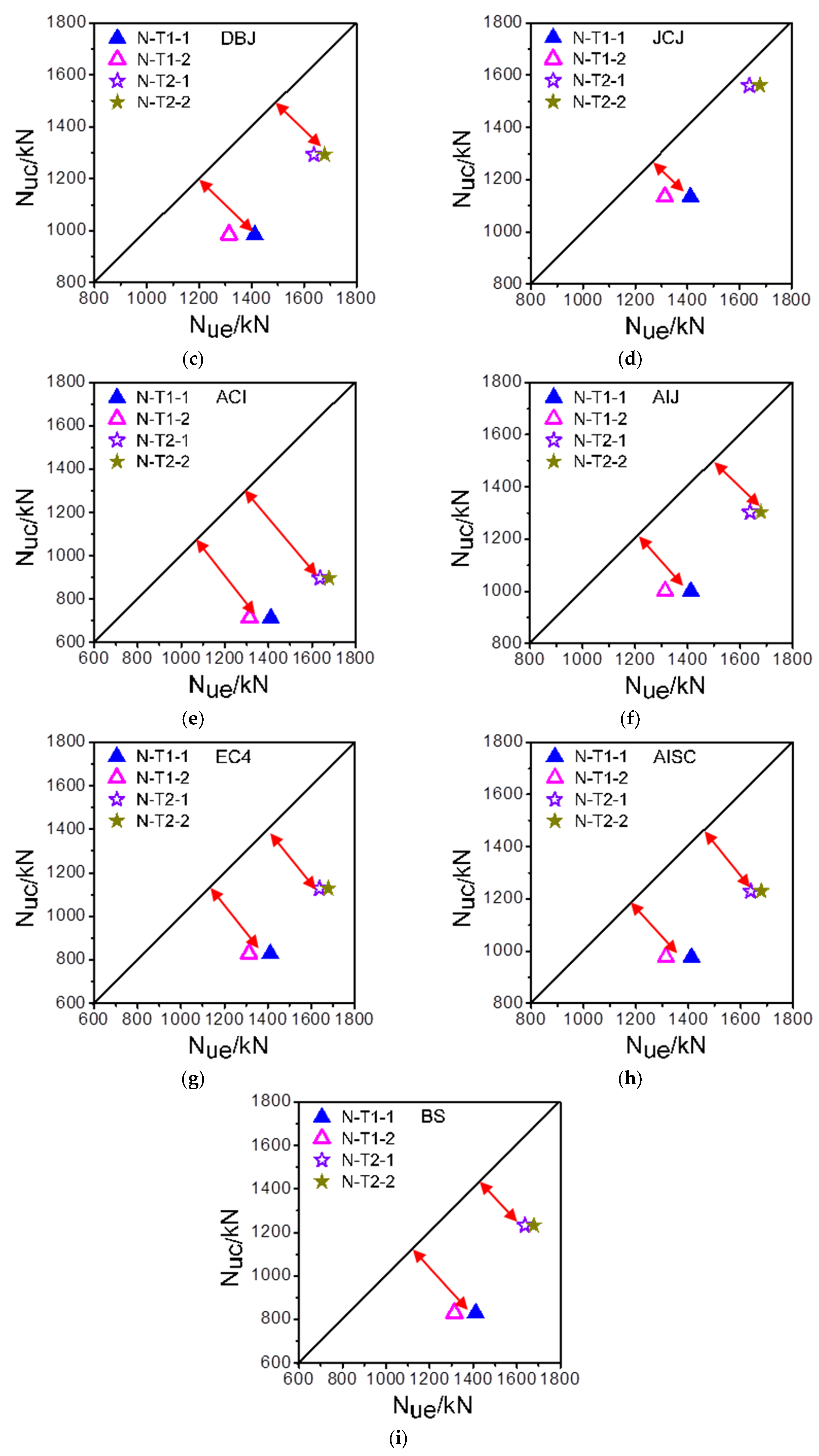
The ultimate loads of the SCCFTST columns from experiments (Nue) and theoretical (Nuc) with different design codes are shown in Table 3 and Figure 5, respectively. Table 3 and Figure 5 present that the ultimate loads from the experiments increase with increasing wall thickness. The ultimate loads calculated with different design codes are lower than those of the corresponding experimental values. This is because the safety factors of steel tube and concrete strength are taken into account in design codes. Therefore, the ultimate loads calculated with different design codes are lower than those of the corresponding experimental values.
The arrows in Figure 5 represent distance from angular bisector to the ultimate loads. The length of the arrow represents the prediction precision of the ultimate load of SCCFTST columns with different design codes. The differences between subfigures of Figure 5 are the arrows length. Figure 5 shown that the distance between the point and the angular bisector in Figure 5e is the longest, and the ultimate loads in this figure are calculated by the design code of ACI. At the same time, the distance between the point and the angular bisector in Figure 5b is the shortest, and the ultimate loads in this figure are calculated by the design code of CECS.
Comparisons of the ultimate loads between the calculated values by different design codes and the experiments are list in Table 4. As shown in Table 4 that the ultimate loads are predicted conservatively using nine different design codes Compared with the ultimate loads from the experiments, the corresponding predicting ultimate loads calculated by DL/T, CECS, DBJ, JCJ, ACI, AIJ, EC4, AISC, and BS are reduced by about 20%, 8%, 25%, 11%, 47%, 24%, 36%, 27%, and 32%, respectively. The ultimate load predicted by ACI design code is the lowest. The average Nuc/Nue and COV of the Nuc/Nue is 0.533 and 0.035, respectively. Therefore, the ultimate load of the SCCFTST columns predicted with ACI design code is the most conservative value. Additionally, the average Nuc/Nue and COV of Nuc/Nue in accordance with CECS design code is 0.922 and 0.069, respectively. Thus, the ultimate load predicted with CECS design code is the most accurate value.

4. Conclusions

Filling thin-walled steel tubes with self-compacting concrete can solve the challenges presented by traditional concrete-filled steel tube columns, such as poor compacting performance and high costs. The performances of SCCFTST columns subject to axial compression from loading to failure are studied in this paper. Effect of the wall thickness on failure modes, load-deformation behaviors, and the ultimate load of SCCFTST columns are comprehensively investigated. The ultimate loads between the experiments and calculated values by design codes are also compared. Conclusions are drawn as following:
  • Typical failure modes of SCCFTST columns with different wall thickness of thin-walled steel tubes present outward buckling. The amount of outward local buckling increased with decreasing wall thicknesses and increasing D/t ratios, respectively.
  • The decreasing rate of the load-deformation curves in the descending branch decreased with increasing wall thickness. However, the ultimate loads of SCCFTST columns increase with increasing wall thickness.
  • The ultimate loads are conservatively estimated by the design codes, including DL/T, CECS, DBJ, JCJ, ACI, AIJ, EC4, AISC, and BS. Compared with the ultimate loads from the experiments, the corresponding decrease rates of the predicted ultimate loads using different design codes are 20%, 8%, 25%, 11%, 47%, 24%, 36%, 27%, and 32%, respectively. Additionally, ACI and CECS are the most conservative and accurate design codes for predicting the ultimate loads of the SCCFTST columns, respectively.
SCCFTST columns can be used as structural materials in civil infrastructures because of their excellent structural and constructional performances. Additionally, modification measures must be taken when predicting the ultimate loads of SCCFTST columns using design codes.

Author Contributions

Conceptualization, Y.W.; Data curation, Y.W.; Formal analysis, Y.W., Y.J. and L.L.; Funding acquisition, Y.W. and L.Z.; Investigation, Y.W.; Methodology, Y.W.; Resources, Y.J. and L.L.; Writing—original draft, Y.W.; Writing—review and editing, Y.W. and L.Z. All authors have read and agreed to the published version of the manuscript.

Funding

This study is supported by Hunan Provincial Natural Science Foundation of China (2020JJ5394), National Science Foundation for Post-doctoral Scientists of China (2022M713497), Science and Technology Department of Jiangxi Province (20202BABL214042), Department of Education of Jiangxi Province (GJJ210656), Teaching Reform Project of Hunan University of Arts and Science in 2021 (JGYB2136), First Class Course of Undergraduate of Theoretical Mechanics in Hunan Province in 2021 (Notice Issued by the Office of Education Department of Hunan Province (2021) No. 322), Science and Technology Innovation and Entrepreneurship Project for College Students of Hunan University of Arts and Science in 2021, Innovation and Entrepreneurship Training Program for College Students of Hunan University of Arts and Science (XDC2021087), First Class Application Courses with Characteristics of Theoretical Mechanics and Design Principles of Concrete Structures in Hunan University of Arts and Science in 2022 (Notice Issued by the Principal’s Office (2022) No. 18), and Labor Education and Practice Base for Concrete Components Manufacturing and Testing of Hunan University of Arts and Science in 2022 (Notice Issued by the Principal’s Office (2022) No. 20).

Data Availability Statement

Not applicable.

Acknowledgments

The authors gratefully acknowledge assistance in experiments for Yongjun Chen, Xuezhi Wang, Fubo Liu and Keqiang Fang from Liaoning University of Technology.

Conflicts of Interest

The authors declare no conflict of interest.

References

  1. Schneider, S.P. Axially loaded concrete-filled steel tubes. J. Struct. Eng. 1998, 124, 1125–1138. [Google Scholar] [CrossRef]
  2. Wang, X.; Fan, F.; Lai, J. Strength behavior of circular concrete-filled steel tube stub columns under axial compression: A review. Constr. Build. Mater. 2022, 322, 126144. [Google Scholar] [CrossRef]
  3. Chang, X.; Luo, X.; Zhu, C.; Tang, C. Analysis of circular concrete-filled steel tube (CFT) support in high ground stress conditions. Tunn. Undergr. Space Technol. 2014, 43, 41–48. [Google Scholar] [CrossRef]
  4. Zhang, J.; Liu, L.; Cao, J.; Yan, X.; Zhang, F. Mechanism and application of concrete-filled steel tubular support in deep and high stress roadway. Constr. Build. Mater. 2018, 186, 233–246. [Google Scholar] [CrossRef]
  5. Xu, F.; Chen, J.; Jin, W. Experimental investigation of thin-walled concrete-filled steel tube columns with reinforced lattice angle. Thin-Walled Struct. 2014, 84, 59–67. [Google Scholar] [CrossRef]
  6. Hassanein, M.F.; Elchalakani, M.; Karrech, A.; Patel, V.I.; Yang, B. Behaviour of Concrete-Filled Double-Skin Short Columns under Compression through Finite Element Modelling: SHS Outer and SHS Inner Tubes; Elsevier: Amsterdam, The Netherlands, 2018. [Google Scholar]
  7. Wu, B.; Zhao, X.Y.; Zhang, J.S.; Yang, Y. Cyclic testing of thin-walled circular steel tubular columns filled with demolished concrete blocks and fresh concrete. Thin-Walled Struct. 2013, 66, 50–61. [Google Scholar] [CrossRef]
  8. Allouzi, R.A.; Almasaeid, H.H.; Salman, D.G.; Abendeh, R.M.; Rabayah, H.S. Prediction of bond-slip behavior of circular/squared concrete-filled steel tubes. Buildings 2022, 12, 456. [Google Scholar] [CrossRef]
  9. Romero, M.L.; Ibañez, C.; Espinós, A.; Portolés, J.M.; Hospitaler, A. Influence of Ultra-High Strength Concrete on Circular Concrete-Filled Dual Steel Columns; Elsevier: Amsterdam, The Netherlands, 2017. [Google Scholar]
  10. Wei, Y.; Zhu, C.; Miao, K.; Zheng, K.; Tang, Y. Compressive performance of concrete-filled steel tube columns with in-built seawater and sea sand concrete-filled FRP tubes. Constr. Build. Mater. 2022, 317, 125933. [Google Scholar] [CrossRef]
  11. Fang, H.; Visintin, P. Structural performance of geopolymer-concrete-filled steel tube members subjected to compression and bending. J. Constr. Steel Res. 2022, 188, 107026. [Google Scholar] [CrossRef]
  12. Mou, B.; Liu, X.; Sun, Z. Seismic behavior of a novel beam to reinforced concrete-filled steel tube column joint. J. Constr. Steel Res. 2021, 187, 106931. [Google Scholar] [CrossRef]
  13. Rahmani, Z.; Naghipour, M.; Nematzadeh, M. Structural behavior of prestressed self-compacting concrete-encased concrete-filled steel tubes beams. Struct. Concr. 2021, 22, 2011–2028. [Google Scholar] [CrossRef]
  14. Ekmekyapar, T. Experimental performance of concrete filled welded steel tube columns. J. Constr. Steel Res. 2016, 117, 175–184. [Google Scholar] [CrossRef]
  15. Roeder, C.W.; Lehman, D.E.; Bishop, E. Strength and stiffness of circular concrete-filled tubes. J. Struct. Eng. 2010, 136, 1545–1553. [Google Scholar] [CrossRef]
  16. Tao, Z.; Han, L.; Zhuang, J. Axial loading behavior of CFRP strengthened concrete-filled steel tubular stub columns. Adv. Struct. Eng. 2007, 10, 37–46. [Google Scholar] [CrossRef]
  17. Liu, D.; Gho, W. Axial load behaviour of high-strength rectangular concrete-filled steel tubular stub columns. Thin-Walled Struct. 2005, 43, 1131–1142. [Google Scholar] [CrossRef]
  18. Gao, S.; Qu, J.; Zhang, S.; Guo, L.; Huang, Z. A comparative study on mechanical and environmental performance of concrete-filled steel tubes using molybdenum tailing aggregate. J. Constr. Steel Res. 2022, 189, 107100. [Google Scholar] [CrossRef]
  19. Zhang, Z.Y.; Sun, Q.; Wang, J.Q.; Zhao, C.; Zhao, B.Z.; Wang, J.T. Experimental and Analytical Research on Flexural Behavior of Concrete-Filled High-Strength Steel Tubular Members. Materials 2022, 15, 3790. [Google Scholar] [CrossRef]
  20. Kilpatrick, A.E.; Rangan, B.V. Tests on high-strength concrete-filled steel tubular columns. Struct. J. 1999, 96, 268–274. [Google Scholar]
  21. Uy, B. Strength of short concrete filled high strength steel box columns. J. Constr. Steel Res. 2001, 57, 113–134. [Google Scholar] [CrossRef]
  22. Han, L.; Yang, Y. Analysis of thin-walled steel RHS columns filled with concrete under long-term sustained loads. Thin-Walled Struct. 2003, 41, 849–870. [Google Scholar] [CrossRef]
  23. Liu, J.; Teng, Y.; Zhang, Y.; Wang, X.; Chen, Y.F. Axial stress-strain behavior of high-strength concrete confined by circular thin-walled steel tubes. Constr. Build. Mater. 2018, 177, 366–377. [Google Scholar] [CrossRef]
  24. Wu, B.; Zhang, Q.; Chen, G.M. Compressive behavior of thin-walled circular steel tubular columns filled with steel stirrup-reinforced compound concrete. Eng. Struct. 2018, 170, 178–195. [Google Scholar] [CrossRef]
  25. Bahrami, A.; Nematzadeh, M. Bond behavior of lightweight concrete-filled steel tubes containing rock wool waste after exposure to high temperatures. Constr. Build. Mater. 2021, 300, 124039. [Google Scholar] [CrossRef]
  26. Luo, C.; Wang, F.; Chen, H.; Qi, A.; Chen, Y. Study on the hysteretic behavior of recycled aggregate concrete-filled steel tube columns containing ferronickel slag. J. Build. Eng. 2022, 46, 103695. [Google Scholar] [CrossRef]
  27. Ayough, P.; Ibrahim, Z.; Sulong, N.R.; Hsiao, P.C. The effects of cross-sectional shapes on the axial performance of concrete-filled steel tube columns. J. Constr. Steel Res. 2021, 176, 106424. [Google Scholar] [CrossRef]
  28. Hassanein, M.F.; Kharoob, O.F. Analysis of circular concrete-filled double skin tubular slender columns with external stainless steel tubes. Thin-Walled Struct. 2014, 79, 23–37. [Google Scholar] [CrossRef]
  29. Tao, Z.; Han, L.; Wang, Z. Experimental behaviour of stiffened concrete-filled thin-walled hollow steel structural (HSS) stub columns. J. Constr. Steel Res. 2005, 61, 962–983. [Google Scholar] [CrossRef]
  30. Li, B.; Ding, F.; Lu, D.; Lyu, F.; Huang, S.; Cao, Z.; Wang, H. Finite Element Analysis of the Mechanical Properties of Axially Compressed Square High-Strength Concrete-Filled Steel Tube Stub Columns Based on a Constitutive Model for High-Strength Materials. Materials 2022, 15, 4313. [Google Scholar] [CrossRef]
  31. Lai, Z.; Han, W.; Wang, Y.; Yang, X.; Huang, W. Shear behavior of high-strength square concrete filled steel tube members. J. Constr. Steel Res. 2022, 196, 107423. [Google Scholar] [CrossRef]
  32. Tao, Z.; Uy, B.; Han, L.H.; Wang, Z.B. Analysis and design of concrete-filled stiffened thin-walled steel tubular columns under axial compression. Thin-Walled Struct. 2009, 47, 1544–1556. [Google Scholar] [CrossRef]
  33. Cai, H.; Xu, L.; Chi, Y.; Yan, Y.; Yu, C.; He, C. Seismic performance of rectangular ultra-high performance concrete filled steel tube (UHPCFST) columns. Compos. Struct. 2021, 259, 113242. [Google Scholar] [CrossRef]
  34. Yang, Y.; Han, L. Experimental behaviour of recycled aggregate concrete filled steel tubular columns. J. Constr. Steel Res. 2006, 62, 1310–1324. [Google Scholar] [CrossRef]
  35. Shehnaz, S.M.; Shah, S.M.I.; Ganesh, G.M. Experimental and theoretical study on rectangular concrete filled steel tube columns subjected to axial compression. Mater. Today Proc. 2022, 65, 771–776. [Google Scholar] [CrossRef]
  36. Wang, Z.; Su, Y.; Wei, J.; Lu, J.; Li, X. The Eccentric Compression Performance of Spirally Stiffened Thin-Walled Square Concrete-Filled Steel Tubular Laminated Composite Members. Buildings 2022, 12, 1151. [Google Scholar] [CrossRef]
  37. Zeghiche, J.; Chaoui, K. An experimental behaviour of concrete-filled steel tubular columns. J. Constr. Steel Res. 2005, 61, 53–66. [Google Scholar] [CrossRef]
  38. Li, L.; Zhang, Y.; Shi, Y.; Xue, Z.; Cao, M. Surface Cracking and Fractal Characteristics of Cement Paste after Exposure to High Temperatures. Fractal Fract. 2022, 6, 465. [Google Scholar] [CrossRef]
  39. Lyu, X.; Xu, Y.; Xu, Q.; Yu, Y. Axial compression performance of square thin walled concrete-Filled steel tube stub columns with reinforcement stiffener under constant high-Temperature. Materials 2019, 12, 1098. [Google Scholar] [CrossRef] [Green Version]
  40. Brouwers, H.; Radix, H.J. Self-compacting concrete: Theoretical and experimental study. Cem. Concr. Res. 2005, 35, 2116–2136. [Google Scholar] [CrossRef]
  41. Revilla-Cuesta, V.; Skaf, M.; Faleschini, F.; Manso, J.M.; Ortega-López, V. Self-compacting concrete manufactured with recycled concrete aggregate: An overview. J. Clean. Prod. 2020, 262, 121362. [Google Scholar] [CrossRef]
  42. Han, L.; Yao, G. Experimental behaviour of thin-walled hollow structural steel (HSS) columns filled with self-consolidating concrete (SCC). Thin-Walled Struct. 2004, 42, 1357–1377. [Google Scholar] [CrossRef]
  43. Wang, Y.; Xiao, L.; Jiang, C.; Jia, Y.; Yang, G.; Li, M.; Tang, X.; Chen, D. Axial Loading Behaviour of Self-Compacting Concrete-Filled Thin-Walled Steel Tubular Stub Columns. Adv. Civ. Eng. 2021, 2021, 1–7. [Google Scholar] [CrossRef]
  44. GB/T 228-2010; Metallic Materials Tensile Testing-Method of Test at Room Temperature. China Standard Press: Beijing, China, 2010.
  45. GB 50081-2002; Standard for Test Method of Mechanical Properties on Ordinary Concrete. China Standard Press: Beijing, China, 2002.
  46. Tao, Z.; Han, L.; Zhao, X. Behaviour of concrete-filled double skin (CHS inner and CHS outer) steel tubular stub columns and beam-columns. J. Constr. Steel Res. 2004, 60, 1129–1158. [Google Scholar] [CrossRef]
  47. An, Y.; Han, L. Behaviour of concrete-encased CFST columns under combined compression and bending. J. Constr. Steel Res. 2014, 101, 314–330. [Google Scholar] [CrossRef]
  48. Thayalan, P.; Aly, T.; Patnaikuni, I. Behaviour of concrete-filled steel tubes under static and variable repeated loading. J. Constr. Steel Res. 2009, 65, 900–908. [Google Scholar] [CrossRef]
  49. DL/T 5085-1999; Code for Design of Steel-Concrete Composite Structure. China Electric Power Press: Beijing, China, 1999.
  50. CECS 28-2012; Technical Specification for Concrete-Filled Steel Tubular Structures. China Planning Publishing House: Beijing, China, 2012.
  51. DBJ T13-51-2010; Technical Specification for Concrete-Filled Steel Tubular Structures. Fuzhou University Press: Fuzhou, China, 2010.
  52. JCJ 01-89; Design and Construction Specification for Concrete-Filled Steel Tubular Structures. Tongji University Press: Shanghai, China, 1989.
  53. ACI 318-1999; Building Code Requirements for Structural Concrete and Commentary. American Concrete Institut: Farmingtion Hills, MI, USA, 1999.
  54. AIJ 1997; Recommendations for Design and Construction of Concrete Filled Steel Tubular Structures. Architectural Institute of Japan: Tokyo, Japan, 1997.
  55. EC4 1994; Design of Composite Steel and Concrete Structures, Part1: General Rules and Rules for Building. European Committee for Standardization: Brussels, Belgium, 1994.
  56. AISC 1999; Specification for Structural Steel Buildings. American Institute of Steel Construction: Chicago, IL, USA, 1999.
  57. BS 5400 1979; Steel Concrete and Composite Bridges, Part 5: Code of Practice for Design Composite Bridges. British Standards Institution: British, UK, 1979.
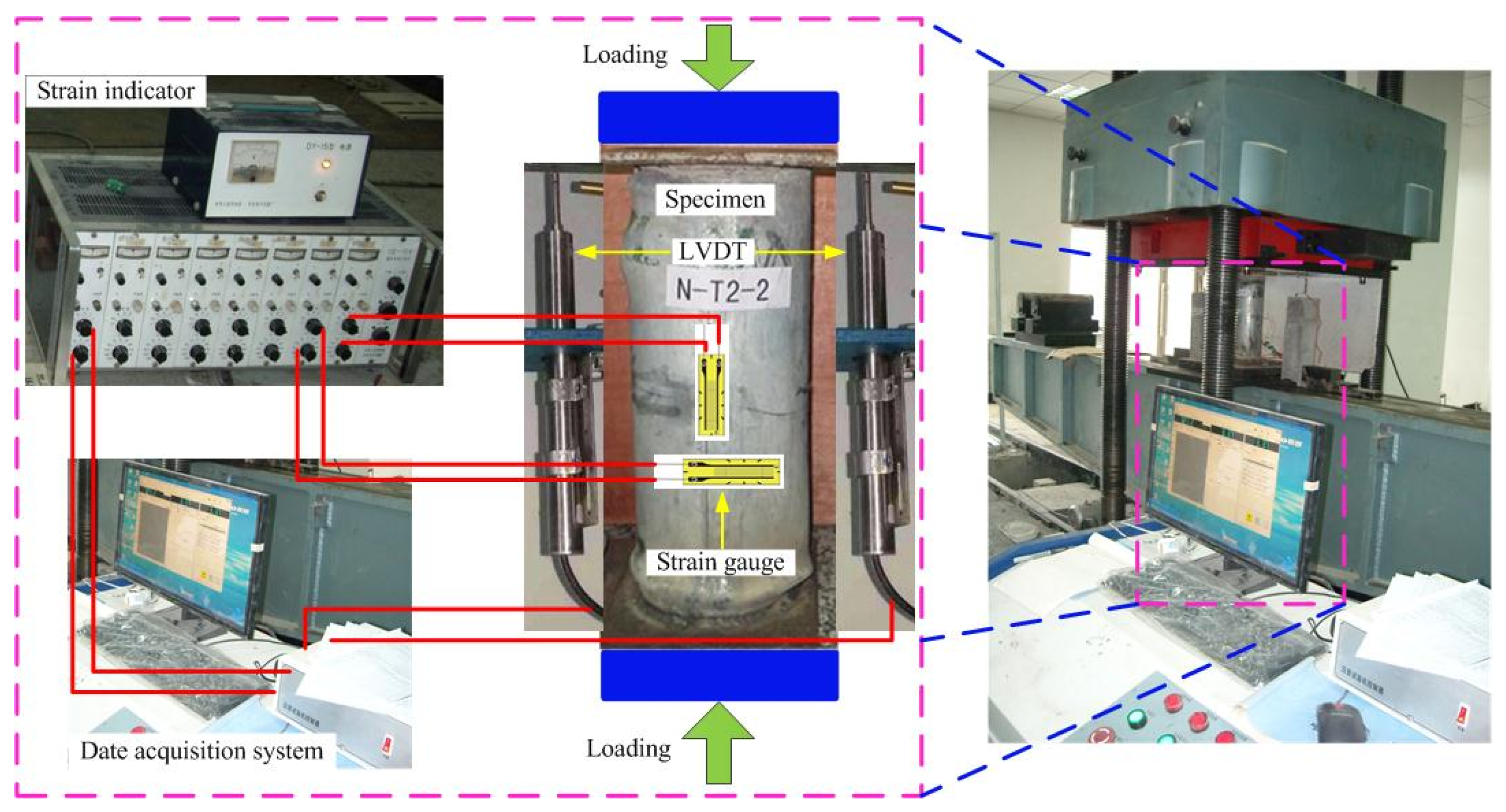
Figure 1. Photographs of loading arrangements.
Buildings 12 02134 g001
Figure 2. Failure mode characteristics of the SCCFTST columns.
Buildings 12 02134 g002
Figure 3. The relationships between load and displacement of the SCCFTST columns.
Buildings 12 02134 g003
Figure 4. (a) The relationships between load and axial/lateral strains of the SCCFTST columns; (b) the relationships between stress and displacement of the SCCFTST columns.
Buildings 12 02134 g004aBuildings 12 02134 g004b
Figure 5. Comparison of the ultimate loads between experiments and calculated values by different design codes of the SCCFTST columns. (a) The experimental ultimate loads and theoretical values calculated with design code of DL/T. (b) The experimental ultimate loads and theoretical values calculated with design code of CECS. (c) The experimental ultimate loads and theoretical values calculated with design code of DBJ. (d) The experimental ultimate loads and theoretical values calculated with design code of JCJ. (e) The experimental ultimate loads and theoretical values calculated with design code of ACI. (f) The experimental ultimate loads and theoretical values calculated with design code of AIJ. (g) The experimental ultimate loads and theoretical values calculated with design code of EC4. (h) The experimental ultimate loads and theoretical values calculated with design code of AISC. (i) The experimental ultimate loads and theoretical values calculated with design code of BS.
Buildings 12 02134 g005aBuildings 12 02134 g005b
Table 1. Mechanical performances and characteristics of the thin-walled steel tubes.
D×t×LL/DD/tYield Strength fyUltimate StrengthModulus of Elasticity EsPoisson’ Ratio
mm3MPaMPaMPa
140 × 1.2 × 4203.0116.7345.0415.01.8 × 1050.30
140 × 3 × 4203.046.7358.3456.72.0 × 1050.28
Table 2. Mix proportion and mechanical performances of the self-compacting concrete.
WaterCementFine AggregateCoarse AggregateFly AshSuperplasticizerfcufckEc
kg/m3kg/m3kg/m3kg/m3kg/m3%MPaMPaMPa
199.0401.5836.5768.5122.10.484.065.83.0 × 104
Table 3. The ultimate loads from experiments and theoretical values using different design codes of the SCCFTST columns.
NumbersNue/kNNuc/kN
DL/TCECSDBJJCJACIAIJEC4AISCBS
N-T1-11411.61073.81186.7985.11134.5713.91000.6829.0976.8830.1
N-T1-21314.01073.81186.7985.11134.5713.91000.6829.0976.8830.1
N-T2-11637.61356.71611.31293.01560.8896.71302.71127.01229.71231.6
N-T2-21678.61356.71611.31293.01560.8896.71302.71127.01229.71231.6
Table 4. Comparison of the ultimate loads between calculated values and experimental results.
NumbersNuc/Nue
DL/TCECSDBJJCJACIAIJEC4AISCBS
N-T1-10.7610.8410.6980.8040.5060.7090.5870.6920.588
N-T1-20.8170.9030.7500.8630.5430.7610.6310.7430.632
N-T2-10.8280.9840.7900.9530.5480.7950.6880.7510.752
N-T2-20.8080.9600.7700.9300.5340.7760.6710.7330.734
Average value0.8040.9220.7520.8880.5330.7600.6440.7300.677
COV0.0370.0690.0530.0760.0350.0490.0700.0360.117
Publisher’s Note: MDPI stays neutral with regard to jurisdictional claims in published maps and institutional affiliations.