Article

The Specificity of Shaping and Execution of Monolithic Pocket Foundations (PF) in Hall Buildings

by
Grzegorz Ludwik Golewski
Department of Structural Engineering, Faculty of Civil Engineering and Architecture, Lublin University of Technology, Nadbystrzycka 40 Str., 20-618 Lublin, Poland
Buildings 2022, 12(2), 192; https://doi.org/10.3390/buildings12020192
Submission received: 20 January 2022 / Revised: 3 February 2022 / Accepted: 4 February 2022 / Published: 8 February 2022
(This article belongs to the Section Building Structures)

Abstract

:
Pocket foundations (PF) are usually used under precast RC columns of steel or RC flyovers and industrial halls. PF is a specific type of foundation in which, apart from standard calculations concerning the fulfilment of the limit states in the base of the footing, the problems related to the appropriate design of its walls in the pocket are also important. In addition to the analytical and design part, a great challenge for constructors is also the selection of the appropriate construction technology of PF in terms of reinforcement preparation as well as the correct shaping of the foundation. The aim of the article is, therefore, to draw attention to the specificity of pocket foundation design—which is part of the structural systems in hall buildings—and to present the main problems that may arise during their construction at individual stages, including guidelines for checking the correctness of the conducted assembly works. The following article describes the main requirements for the construction of PF with particular attention to the type of surface present inside the pocket. The main problems related to the PF construction are also presented, and the methodology of assembling the precast columns in the footings is described. At the end of the manuscript, it is also discussed how to check and control the correctness of the skeleton installation works in hall buildings in order to prevent too large deviations in the assembled structure.

1. Introduction

Modern industrial plants constitute a system of synergistically cooperating industrial facilities and special facilities. The first group includes mainly production halls and all buildings directly related to production processes, while the second group includes the following objects: storage tanks, chimneys, cooling towers, etc. [1].
The main industrial processes most often take place in halls, that is, one-storey structures with long-span roofs and a small number of supports [2]. The most common structural systems in this type of facility are flat slab-column, frame or arch connections. In static diagrams, halls most often consist of a system of columns rigidly fixed in the foundations and connected by a flexible joint (slab-column system) or rigid (frame system) [3] system in the upper part of the hall [4,5]. An exemplary static diagram and an axonometric view of a single-nave hall building are shown in Figure 1, while a cross-section of a reinforced concrete hall built on pocket foundations (PF) is shown in Figure 2. All the characteristic structural elements of the hall buildings built on the PF are marked in both figures.
The basic foundation types in the halls are cast in-situ or precast pocket foundations. This type of foundation must be designed and calculated in such a way that it is able to transfer significant bending moments as well as vertical and horizontal forces that exist at the connection of the columns with the pocket foundation [6,7,8,9,10]. These structures were considered important so that recommendations appeared in the current standard for the design of reinforced structures, i.e., Eurocode 2 [11], regarding the calculation procedures. On the other hand, the literature lacks detailed and precise guidelines describing the procedures related to the design and construction of these specific structures. Filling this gap is particularly important as PFs are components of hall buildings, which means that they may be exposed to static, dynamic and fatigue loads [12,13,14,15,16,17,18]. Therefore, inadequate procedures when constructing structural systems in the skeleton hall buildings may result in the formation of primary microcracks in the concrete structure connecting the PF with the column. As a consequence, this may lead to the initiation of destructive processes at the point of the connection of the pocket foundation with the column as well as the beginning of failure condition in the hall structure [19,20,21,22,23,24,25,26].
Therefore, when constructing PF-column arrangements, it is very important to:
  • Construct PF in accordance with the guidelines;
  • Properly select and finish the interior surface of PF;
  • Precisely install the column in the PF;
  • Precisely connect the column with the PF;
  • Check the correctness of the connection and, if necessary, correct any dimensional deviations.
The aim of the article is, therefore, to draw attention to the specificity of pocket foundation design—part of the structural systems in hall buildings—and to present the main problems that may arise during their construction at individual stages, including guidelines for checking the correctness of the conducted assembly works.

2. Background and Significance of the Study

Pocket foundations are usually used under precast RC columns of steel or RC flyovers and industrial halls. The view of the frame of the hall with a mixed structure, i.e., with RC columns and steel girders, during its installation with the connection of the column to PF, is shown in Figure 3.
The pocket foundation is a specific type of foundation in which, apart from standard calculations concerning the fulfilment of the limit states in the base of the footing, the problems related to the appropriate design of its walls in the pocket are also important. The cross-sectional area of the reinforcement in the footing base is determined with regard to its bending and punching, and the pocket walls are designed according to the forces occurring in them. It is also important to check the pressure of the column to the walls of the pocket.
The recommendations included in [11] should be taken into account when designing the reinforcement of the pocket footing of this type. In this standard, two cases of pocket foundation design are considered, i.e.:
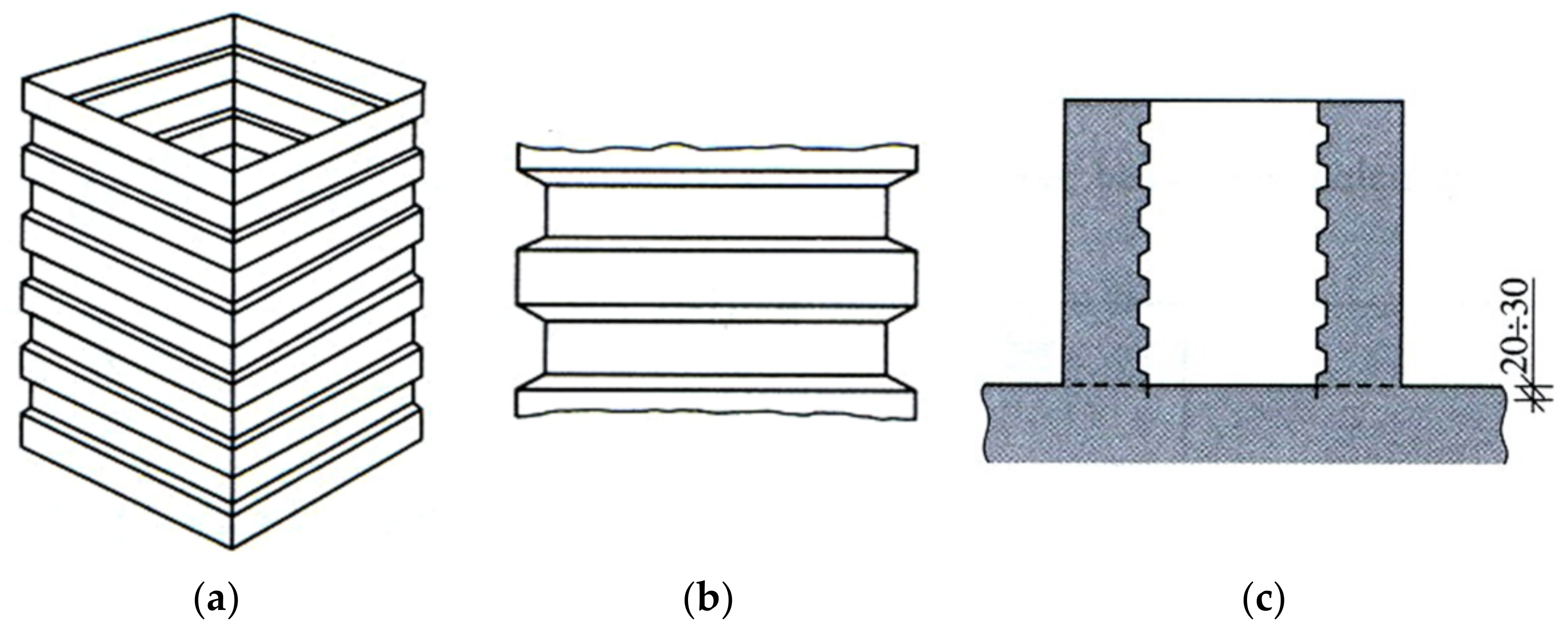
  • With keyed contact surface;
  • With smooth contact surface.
The theoretical and experimental study of the pocket connections with a smooth surface interface of precast concrete structures were presented in several papers, for example, [27,28]. However, in the literature, there are no reports or design recommendations regarding PF with a more favourable keyed surface. Therefore, in order to fill this gap, these guidelines will be included in this article.
In calculations of PF, the tangential forces acting on the pocket’s wall should be taken into account. For this purpose, a computational model was assumed in [11], in which the external forces from the column: MSd, VSd and NSd are transferred to the foundation by three groups of compressive forces: F1, F2 and F3, on both sides of the pocket and directly below it, taking into account the friction of concrete, μ (Figure 4).
The distribution of forces in a connection depends on the dimensions of its elements, the design solution and the proportion of forces. For the stress distribution shown in Figure 4, a calculation model has been formulated that includes three equilibrium conditions:
V S d V R d = F 1 F 2 μ F 3 N S d N R d = μ F 1 μ F 2 + F 3 M S d M R d = V R d y + 0.5 N R d h + μ F 2 h + 0.9 y F 1 0.1 y F 2 0.5 h F 3
When using the presented computational model, attention should be paid to the:
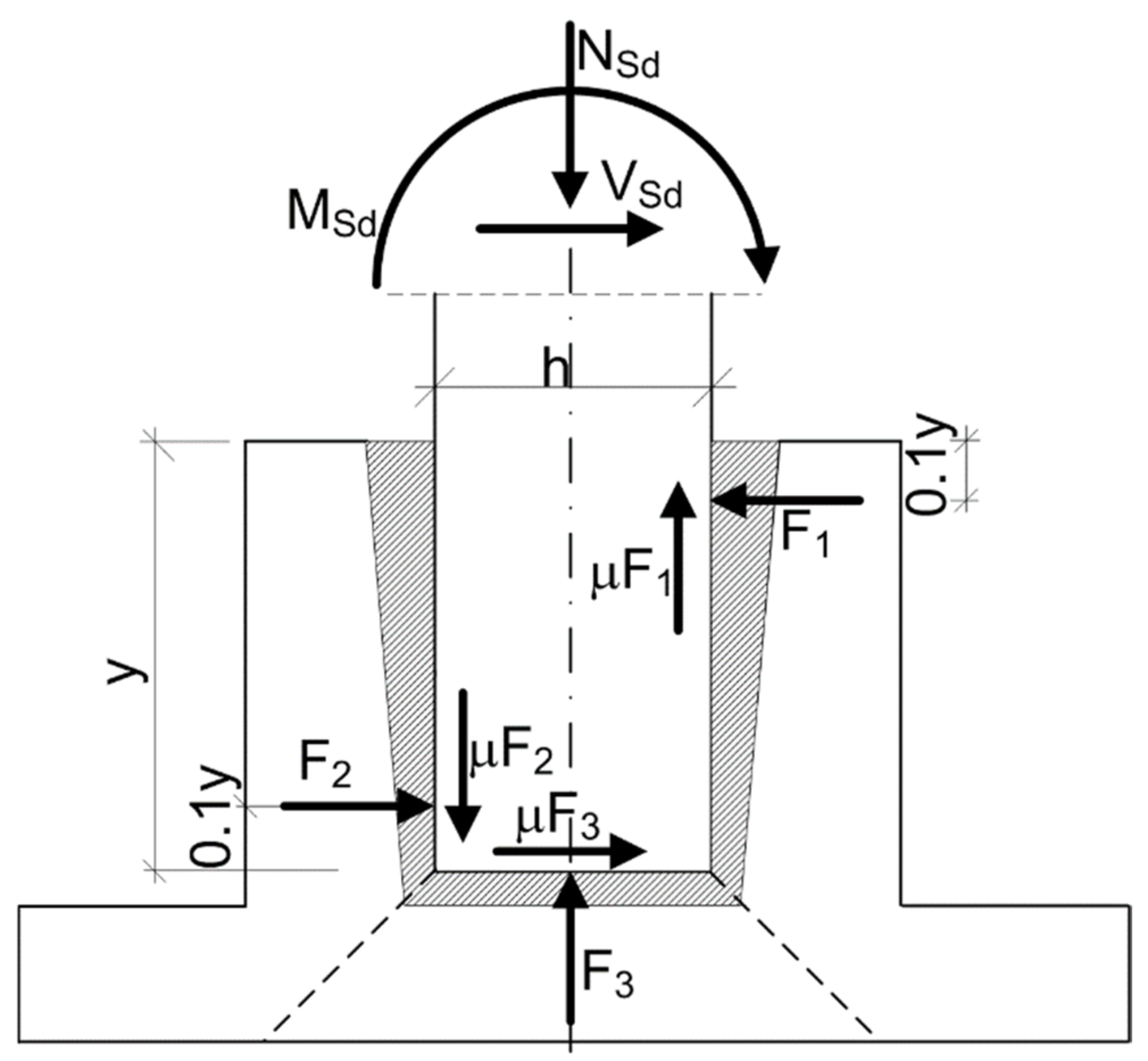
  • Design of reinforcement for force F1;
  • Transfer of force F1 along the vertical walls of the footing;
  • Correct anchor installation of the main reinforcement of the column and the footing’s walls;
  • Ensuring the shear load capacity of the column;
  • Checking punching load capacity of PF.
The solution of the above system of three equations (1) contained in [11] allows for the determination of the cross-sectional area of the reinforcement in the PF walls. The reinforcement, shown in Figure 5, for a footing with an associated reinforcement skeleton consists of:
  • Vertical bars working in bending (Figure 5—1);
  • Horizontal reinforcement in the form of closed frames working in tension, placed in the upper part of the pocket (Figure 5—2);
  • Structural reinforcement located at the height of PF (Figure 5—3).
Additionally, it should be clearly emphasised that with incorrectly designed tensile reinforcement (Figure 5—2), the upper part of the PF may tear.
Moreover, the determination of the reinforcement in the PF base is also important. Such reinforcement is most often in the form of orthogonal meshes (Figure 5—4).
Apart from the rules for calculating and selecting reinforcement in PF in terms of the review of the current achievements in the field of PF design, the latest guidelines for the selection of components for concrete in these structural elements were also presented. It has been established that the advantageous solution is the use of crushed or recycled aggregates for concrete [29,30] and binders modified with mineral additives [31,32,33,34,35,36,37,38,39], admixtures [40,41,42,43,44] and micro-fillers [45,46,47,48,49,50,51,52]. Such treatments allow limiting the adverse damage to PF, which is the result of dynamic loads occurring during the operation of machines located in the hall buildings [12,53,54,55,56,57,58,59,60,61,62].
In addition to the analytical and design parts, a great challenge for constructors is also the selection of the appropriate construction technology of PF in terms of preparation of reinforcement as well as the correct shaping of the foundation. The issue of the correct construction of the footing is very important as the upper pocket of the foundation is the place where the skeleton columns of the hall building are placed. Hence, the precise construction of the foundation also guarantees smaller deviations of the columns from the geodetic axes of the hall, and a more precise location of the remaining elements of the structural skeleton [63].
Since the problems related to the construction and realisation of PF have not been fully presented in the literature so far, the following article describes the main requirements for the construction of PF with particular attention to the type of surface present inside the pocket. The guidelines for PF with both smooth and wrought surfaces are presented in this article. The main problems related to PF construction are also presented, and the methodology of assembling the precast columns in the footings is described. At the end of the manuscript, we also discuss how to check and control the correctness of the skeleton installation in hall buildings to prevent large deviations in the assembled structure. All the issues described in the article are supplemented with photos and diagrams from the various stages of construction in the scope of the presented problem (from the author’s collection).

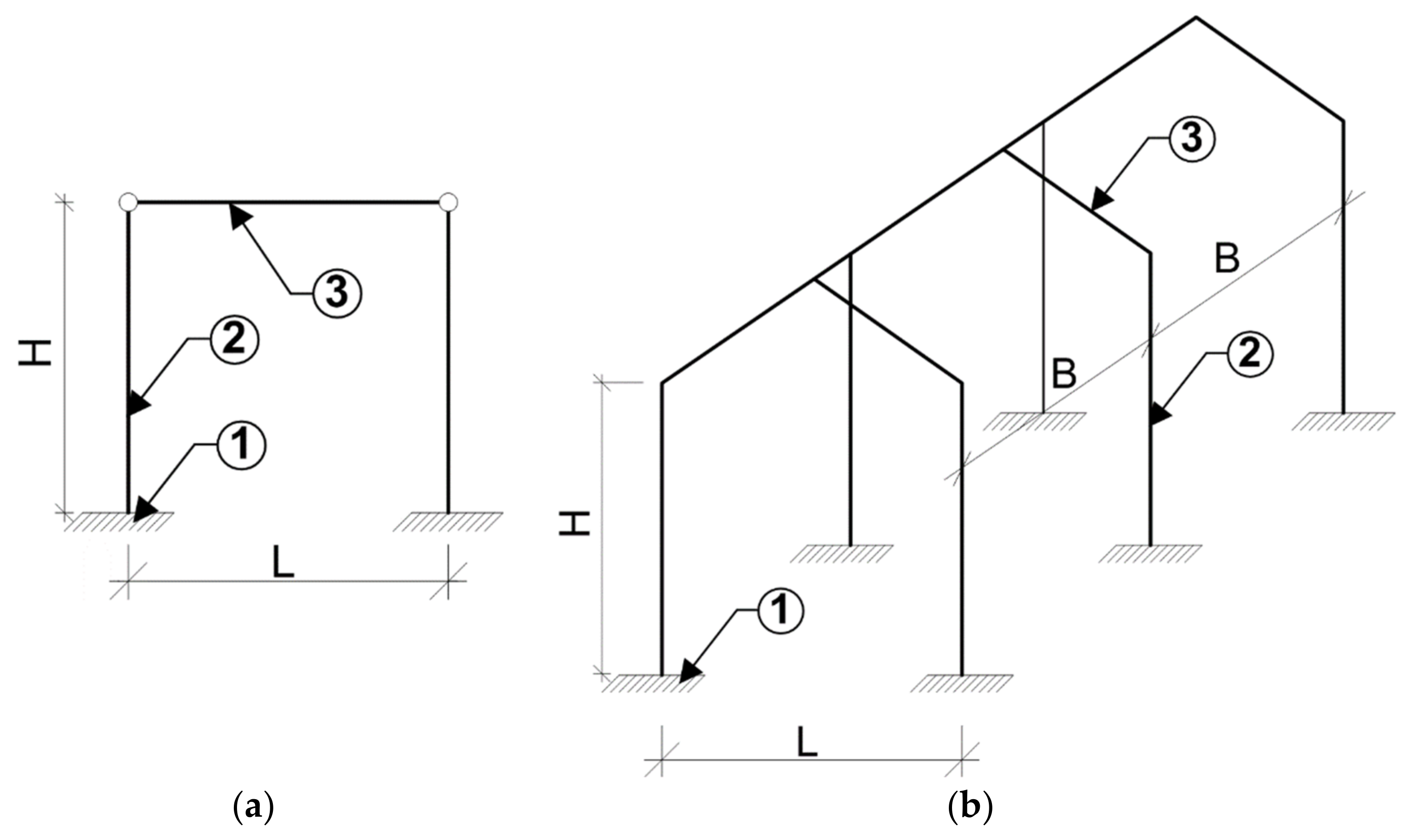
3. Structure of Pocket Foundations

3.1. Foundation Requirements

In practice, PFs are constructed in formwork as monolithic or precast, and then columns are placed in the pockets of these footings. It is also possible in certain special situations to use simpler solutions such as the so-called column footings (precast elements in the form of foundations directly connected to the columns), which reduce the problematic assembly works on the construction site. However, such structures are not suitable for use in all types of halls, and therefore the most common solution in the case of this type of foundation is monolithic pocket footings.
Such foundations, depending on the loads, are constructed with one, two or three offsets (Figure 6), and their number depends primarily on the height of the footing, hPF. The number of offsets in PF is determined on the basis of the relationships given in Table 1 [64].
When selecting the remaining PF dimensions, the most important parameters are (Figure 6):
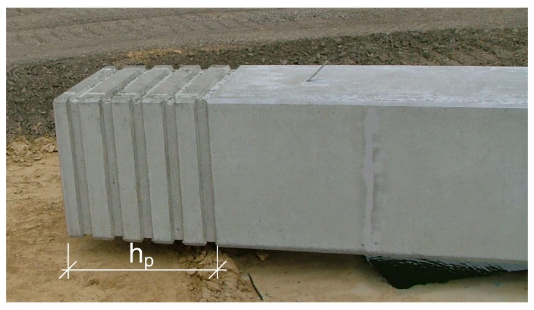
  • Depth and width of the pocket, i.e., hp and bp;
  • Number of offsets, i.e., h1, h2, h3, b1, b2.
Due to punching, part of the foundation should be constructed sufficiently deep, below the bottom of the pocket (not less than 200 mm), and the space between the column and pocket should be left, which will be filled with monolithic concrete in the final stage of the installation of the columns. It is required that the distance between the column and the pocket is at least 75 mm in the upper part and 50 mm in the lower part (Figure 6).
The requirements for the dimensions of PF hp and bp are mainly related to the appropriate anchoring of the column reinforcement within the pocket and the correct transfer of all internal forces from the column to the foundation so that it does not suffer unforeseen damage during operation. The pocket width is selected as the largest of the values according to Formula (2), while the required pocket depth depends on several parameters such as the dimensions of the column (cross-section height hcol and cross-section width bcol) and the value of the eccentricity on which the vertical force acts, e0 and bp [65].
b p m a x 250   mm 0.75 · h 3 h c o l + b c o l + 4 · 75   mm 6 0.5 · h c o l

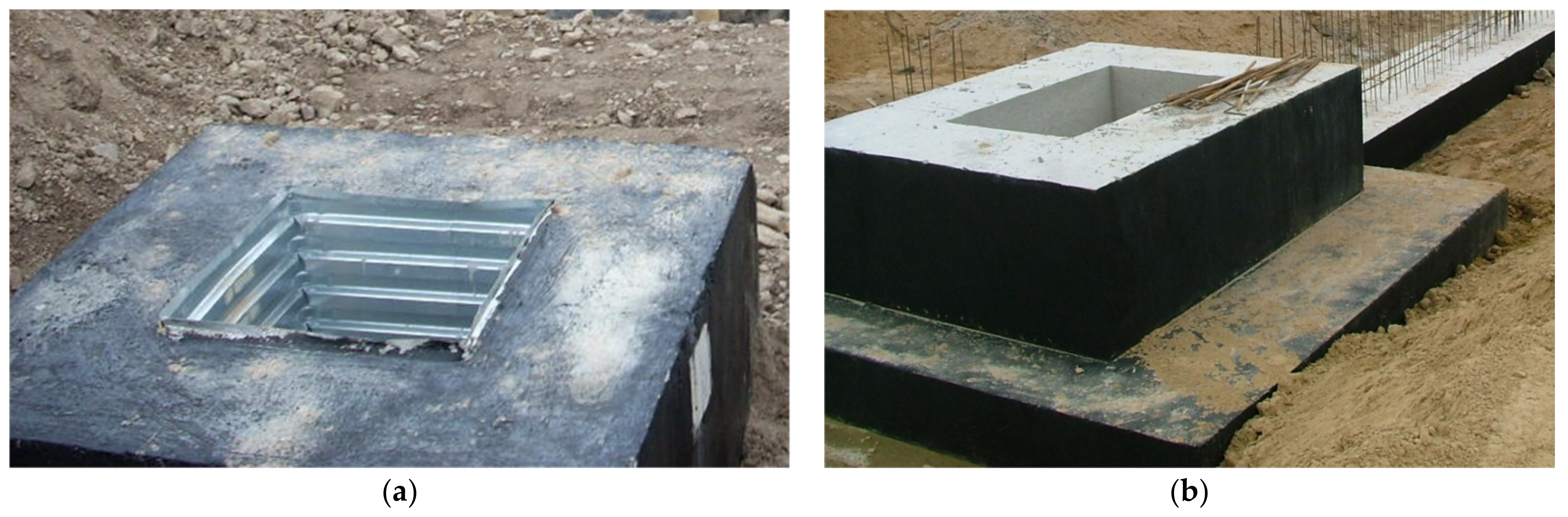
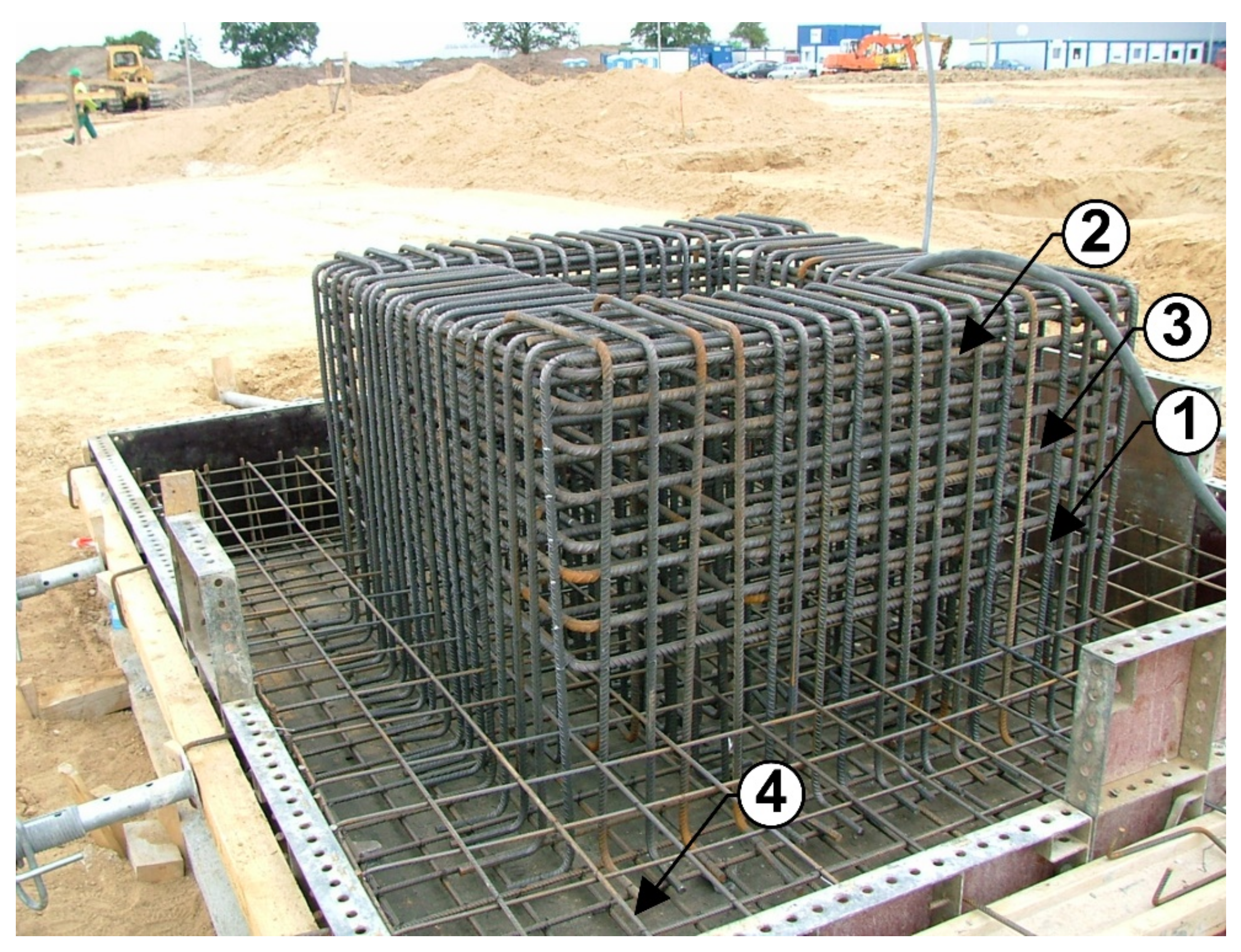
3.2. Design of the Inside of the Pocket

In order to ensure the correct transfer of forces from the column to the walls of the pocket, their internal surfaces should be carefully prepared. Most often, they are smooth (Figure 7a); however, a more advantageous solution is to shape the internal surfaces of the pocket as keyed with a special geometry (Figure 7b). This technological solution ensures better adherence between the surface of the pocket and the monolithic concrete and also allows for the transfer of tangential forces to a better degree.
The keyed surface inside the pocket footing is obtained by using metal forming inserts during the construction of the foundation, constituting the internal formwork of the pocket (Figure 8). When setting up the footing formwork, such an insert can be placed in the PF according to one of the following two methods, i.e.:
  • Special composite with its structure—in the case of concreting the foundation base together with the pocket at one time;
  • Anchored in the concrete of the slab foundation to a depth of several dozen mm (Figure 8c)—in the case of two-stage concreting; slab of PF and pocket separately.
The view of PF with the forming insert is shown in Figure 9a. For comparison, Figure 9b shows the foundation, the pocket of which is finished with a smooth surface, i.e., without the use of an insert forming keyed surface.
If RC columns are to be placed in the PF, it is also possible to make a keyed surface (while forming the columns) at their ends, along the length of the column equal to the pocket depth hp. The required wrought shapes, in this case, are obtained by a special design of the shape of the columns in their lower zone. An example of a column with a shaped keyed surface is shown in Figure 10.

4. Stages in the Process of Construction of Monolithic PF and Installing Columns in Them

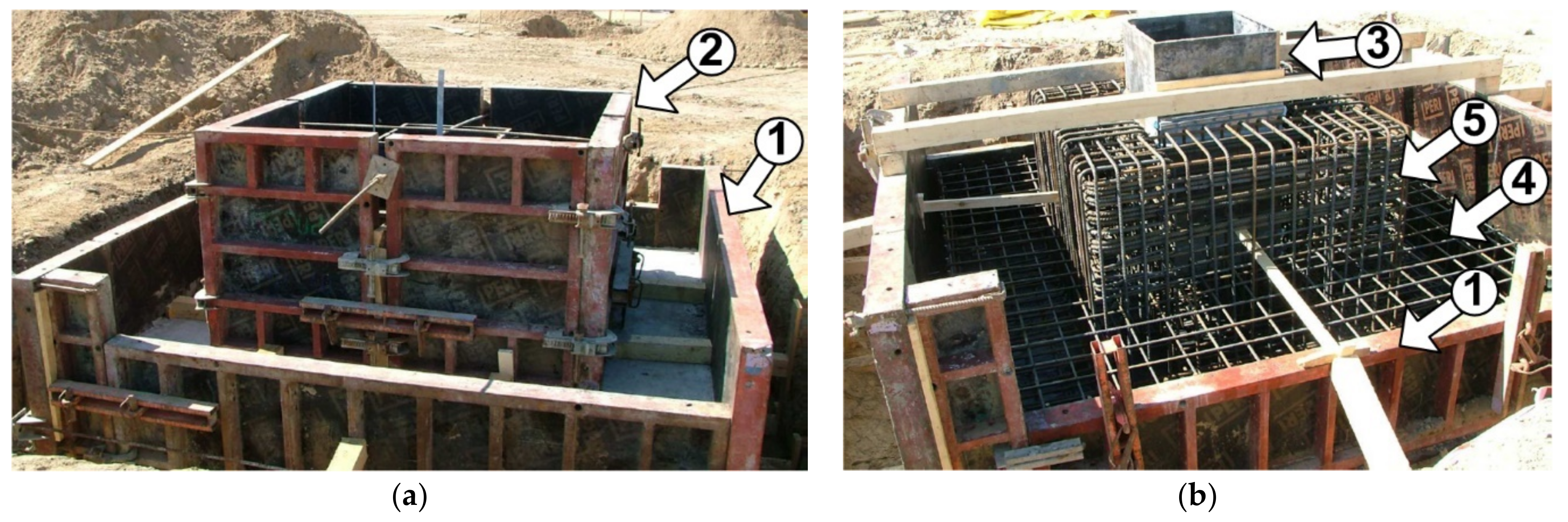
4.1. Construction of a Footing

In the construction of monolithic PFs, several main stages can be distinguished that are directly related to each other. In the first phase, the work consists of proper preparation of the base for the foundation so that it is easy to set up formwork for both the footing and the pocket. For this purpose, a sand bed with an appropriate degree of compaction should be prepared, and then a 10 cm layer of base concrete with a strength class of at least C8/10 should be laid, according to Eurocode 2 [11].
After this stage, the formwork of the footing base should be set up in the shape that results from the dimensions of the lowest offset, and then the bottom reinforcement of the PF should be laid, resulting from its calculations for bending. If the foundation is planned to be constructed in several stages, it is possible to fill the boarded part of the footing with concrete mix; if it is to be made during one concreting, the next step is to set the pocket formwork and other offsets.
If the design includes a keyed-shaped surface of the pocket, it is important (in the case of multi-stage concreting) to place a metal forming insert in the hardening concrete of the lower layer. Then, the reinforcement skeleton of the pocket should be prepared, remembering the correct placement of the vertical and horizontal reinforcement bars as well as the structural reinforcement, in accordance with the diagram in Figure 5. The last steps in the process of construction of PF are the concreting of boarded parts of the foundation and proper care of the concrete once concreted. Examples of PF formworks and reinforcements in the case of one- and two-stage formations are shown in Figure 11.

4.2. Installation of the Columns in the Pocket Footings

In typical situations, columns can be placed in PF after 28 days from the concreting; however, in the current realities of building with a continuous shortage of time, it is permissible to start assembly works after 14 days from the concreting of the footings. The columns should be installed very carefully, with detailed guidelines, and the procedure path according to the following stages:
  • Stage 1: pouring a 5 cm layer of levelling base concrete on the bottom of the pocket, on which the columns will be placed;
  • Stage 2: installation of columns in the footings with the use of cranes (usually self-propelled) with the use of special slings; this operation should be conducted very precisely in order to minimise the possible damage of the pocket in the event of the column hitting the wall; in order to ensure adequate comfort of installation works, it should be borne in mind that the installation of columns should be suspended in bad weather conditions, i.e. during strong winds, the speed of which exceeds 5.0 m/s;
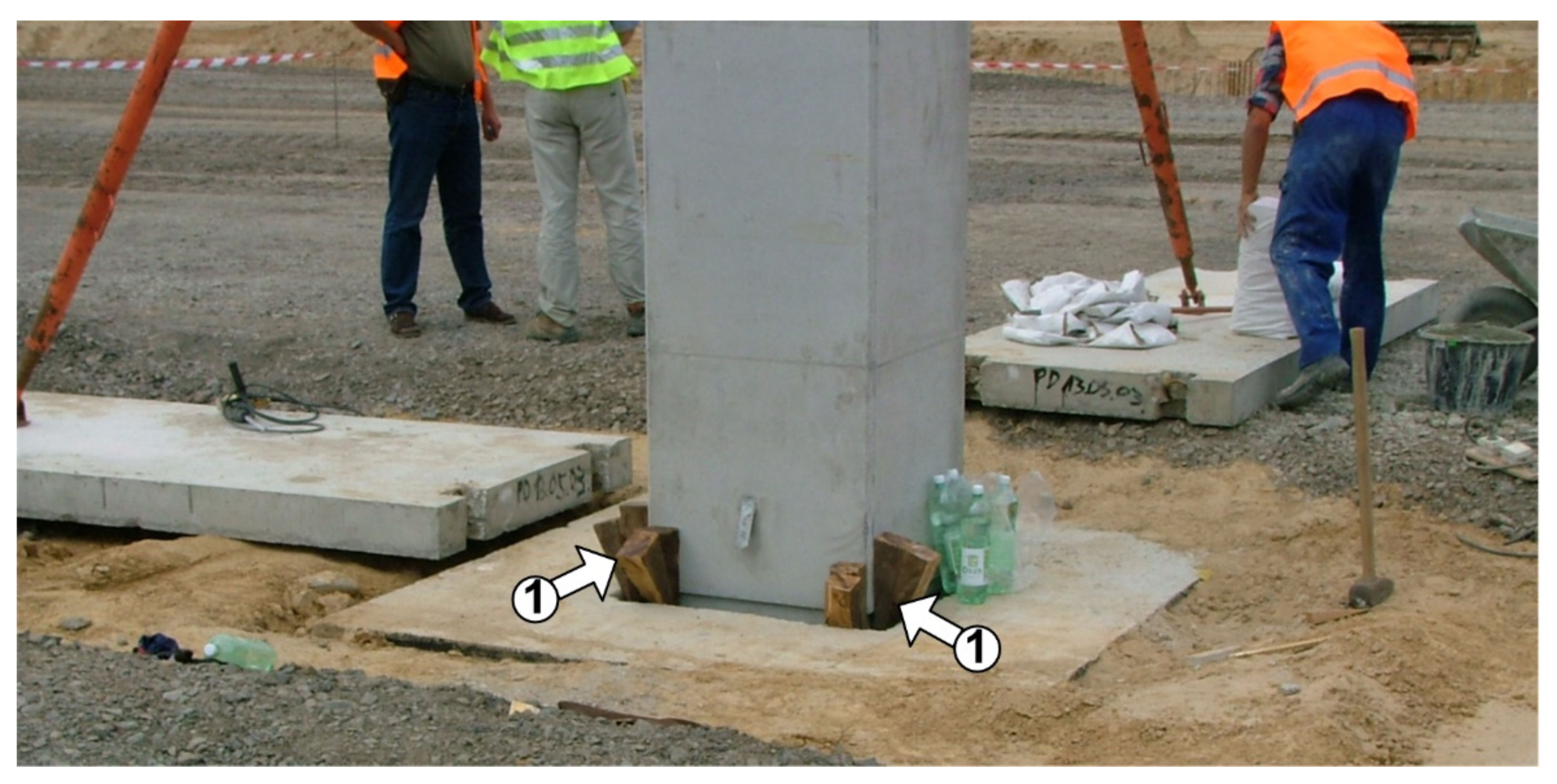
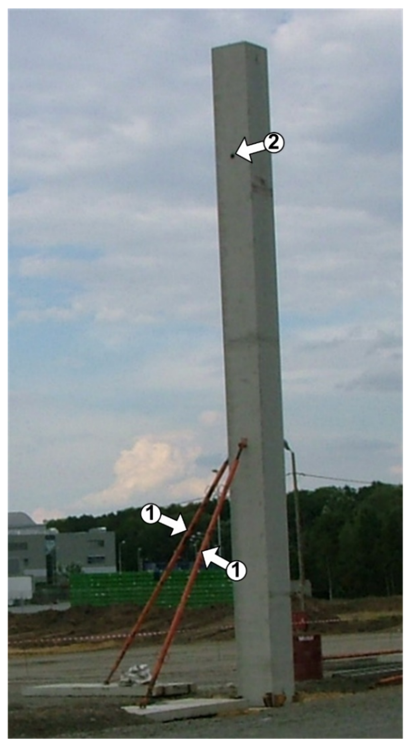
  • Stage 3: vertical alignment of the columns with the use of geodetic measurements; for this purpose, specially prepared oak wedges are hammered to the appropriate depth between the edge of the pocket and the column (at least six wedges are required); an example of column wedging in PF is shown in Figure 12;
  • Stage 4: temporary support of the columns and release of the crane hooks in their upper part (Figure 13);
  • Stage 5: geodetic checks of the correct installation of columns and possible corrections of their positioning;
  • Stage 6: placing monolithic concrete inside the pocket; due to the narrow space between the column and the pocket, it is recommended to use concrete with smaller grain size (preferably with a maximum grain size of Dmax = 8 mm) and a strength class higher than the structural concrete PF;
  • Stage 7: precise compaction of monolithic concrete in the pocket space, preferably with an internal vibrating poker with a thin tip, e.g., needle.

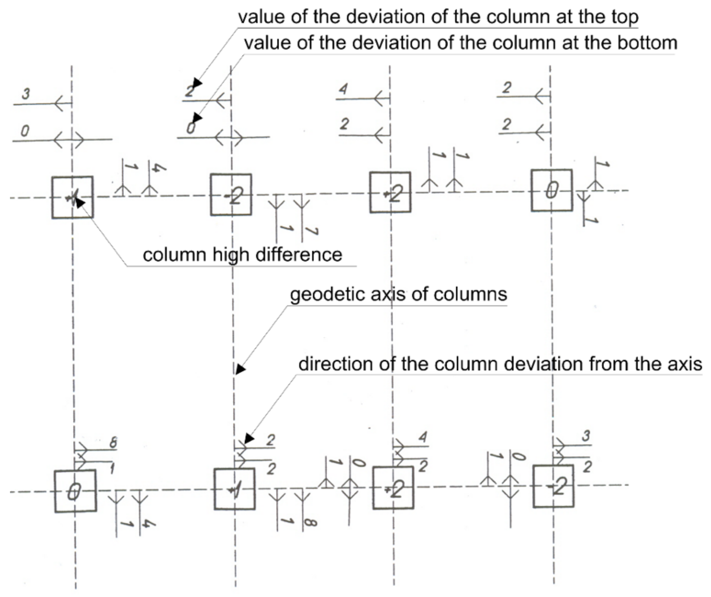
5. Control of the Correctness of the Conducted Assembly Works

After installing all the columns in PF, geodetic measurements of the correctness of the works performed should be carried out before proceeding to further assembly works. Their purpose is to capture all the deviations of the columns in relation to the hall axes and to show any differences in height between the individual columns.
An example of the geodetic map, including control measurements of the columns after assembly, is shown in Figure 14. The sketch from measurements should always include:
  • Values of the upper and lower deviations of the columns (mm);
  • Directions of column deviations marked with arrows (right or left side);
  • Differences in the height of columns (mm) determined from the highest point in relation to the zero of the building.
Thanks to the sketches made in this way, it is possible to correct further construction works and avoid overlapping of assembly deviations in the subsequent stages of erecting the skeleton of the hall building.

6. Summary and Conclusions

Reinforced concrete PFs are used mainly as elements for transferring loads to the ground in the structural systems of industrial halls or loading flyovers. In this type of facility, apart from the typical static loads, there are often dynamic effects (e.g., operation of overhead cranes), which require that the foundation of the building is able to prevent the transmission of harmful vibrations. The literature studies and experience from construction practice allow us to conclude that it may be helpful in the construction and implementation of this type of foundation in hall buildings.
Therefore, when determining the shape and dimensions of the foundations, attention should be paid to:
  • Proper selection of the depth and width of the pocket and the number of offsets, which mainly depend on the height of PF and the dimensions of the column’s cross-section (Figure 6);
  • Leaving enough space between the walls of the pocket and the column (Figure 6) and use of a keyed-shaped inner surface of the pocket (Figure 7b and Figure 9a).
  • However, during the construction of PF, attention should be paid to the following:
  • Correct execution of the reinforcement of the pocket’s walls (Figure 5) as well as correct and precise conduct of works related to the assembly of columns in the pocket (Figure 12 and Figure 13);
  • Preparing a geodetic sketch from the control measurements of columns after installation (Figure 14).

Funding

This research received no external funding.

Institutional Review Board Statement

Not applicable.

Informed Consent Statement

Not applicable.

Data Availability Statement

No new data were created or analysed in this study. Data sharing is not applicable to this article.

Conflicts of Interest

The author declares no conflict of interest.

References

  1. Wang, S.; Sinha, R. Life Cycle Assessment of Different Prefabricated Rates for Building Construction. Buildings 2021, 11, 552. [Google Scholar] [CrossRef]
  2. Zabielski, J.; Srokosz, P. Monitoring of Structural Safety of Buildings Using Wireless Network of MEMS Sensors. Buildings 2020, 10, 0193. [Google Scholar] [CrossRef]
  3. Brunesi, E.; Nascimbene, R.; Bologini, D.; Bellotti, D. Experimental investigation of the cyclic response of reinforced precast concrete framed structures. PCI J. 2015, 60, 57–79. [Google Scholar] [CrossRef]
  4. Golewski, G.L. Validation of the Favorable Quantity of Fly Ash in Concrete and Analysis of Crack Propagation and its Length—Using the Crack Tip Tracking (CTT) Method—In the Fracture Toughness Examinations under Mode II, Through Digital Image Correlation. Constr. Build. Mater. 2021, 296, 122362. [Google Scholar] [CrossRef]
  5. Nowogońska, B. Diagnoses in the Aging Process of Residential Buildinds Constructed Using Traditional Technology. Buildings 2019, 9, 126. [Google Scholar] [CrossRef] [Green Version]
  6. Pul, S.; Senturk, M.; Ilki, A.; Hajirasouliha, I. Experimental and Numerical Investigation of a Proposed Monolithic-Like Precast Concrete Column-Foundation Connection. Eng. Struct. 2021, 246, 113090. [Google Scholar] [CrossRef]
  7. El-Ariss, B.; Mansour, M.; El-Maaddawy, T. Effects of Web Weight Reduction and Skew Angle Variation on Behavior of RC Inverted T-Beams. Buildings 2021, 11, 451. [Google Scholar] [CrossRef]
  8. Priya, A.K.; Nagan, S.; Rajeswari, M.; Nithya, M.; Priyanka, P.M.; Vanitha, R. Analytical Investigation on the Seismic Behaviour of Precast Pocket Foundation Connection. Int. J. Adv. Eng. Tech. 2016, 7, 214–218. [Google Scholar]
  9. Osanai, Y.; Watanabe, F.; Okamoto, S. Stress Transfer Mechanism of Socket Base Connections with Precast Concrete Columns. ACI Struct. J. 1996, 93, 266–276. [Google Scholar]
  10. Canha, R.M.F.; El Debs, A.L.d.C.; El Debs, M.K. Design Model for Socket Base Connections Adjusted from Experimental Results. Struct. Concr. 2007, 8, 3–10. [Google Scholar] [CrossRef]
  11. The European Union Per Regulation EN 1992-1-1. Eurocode 2: Design of Concrete Structures—Part 1-1: General Rules and Rules for Buildings. 2004. Available online: https://www.phd.eng.br/wp-content/uploads/2015/12/en.1992.1.1.2004.pdf (accessed on 2 December 2021).
  12. Park, S.; Beak, J.; Kim, K.; Park, Y.-J. Study on Reduction Effect of Vibration Propagation Due to Internal Explosion Using Composite Materials. Int. J. Concr. Struct. Mater. 2021, 15, 30. [Google Scholar] [CrossRef]
  13. Golewski, G.L. Physical Characteristics of Concrete, Essential in Design of Fracture-Resistant, Dynamically Loaded Reinforced Concrete Structures. Mater. Des. Proc. Comm. 2019, 1, 82. [Google Scholar] [CrossRef] [Green Version]
  14. Lyratzakis, A.; Tsompanakis, Y.; Psarropoulos, P.N. Efficient Mitigation of High-speed Train Vibrations on Adjacent Reinforced Concrete Buildings. Constr. Build. Mater. 2022, 314, 125653. [Google Scholar] [CrossRef]
  15. Maneetes, H.; Memari, A.M. Introduction of an Innovative Cladding Panel System for Multi-Story Buildings. Buildings 2004, 4, 418–436. [Google Scholar] [CrossRef] [Green Version]
  16. Hemamahti, L.; Jaya, K.P. Behaviour of Precast Column Foundation Connection under Reverse Cyclic Loading. Adv. Civ. Eng. 2021, 2021, 6677007. [Google Scholar] [CrossRef]
  17. Golewski, G.L. On the special construction and materials conditions reducing the negative impact of vibrations on concrete structures. Mater. Today. Procs. 2021, 45, 4344–4348. [Google Scholar] [CrossRef]
  18. Jean, N.; Gormley, M. A Photogrammetric Technique for Developing Boundary Wquations for Flexible Sheath Waterless Trap Seals as Used in Building Drainage Systems. Buildings 2021, 11, 136. [Google Scholar] [CrossRef]
  19. Akram, A. The Overview of Fracture Mechanics Models for Concrete. Arch. Civ. Eng. Env. 2021, 1, 376–385. [Google Scholar] [CrossRef]
  20. Słowik, M. The Role of Aggregate Granulation on Testing Fracture Properties of Concrete. Frat. Int. Strutt. 2021, 58, 47–57. [Google Scholar] [CrossRef]
  21. Gautham, S.; Sasmal, S. Nano-scale Fracture Toughness of Fly Ash Incorporated Hydrating Cementitious Composites Using Experimental Nanoidentation Technique. Theor. Appl. Fract. Mech. 2022, 117, 103180. [Google Scholar] [CrossRef]
  22. Golewski, G.L. Evaluation of Fracture Processes under Shear with the Use of DIC Technique in Fly Ash Concrete and Accurate Measurement of Crack Path Lengths with the Use of a New Crack Tip Tracking Method. Measurement 2021, 181, 109632. [Google Scholar] [CrossRef]
  23. Golewski, G.L. An Analysis of Fracture Toughness in Concrete with Fly Ash Addition, Considering All Models of Cracking. IOP Conf. Ser. Mater. Sci. Eng. 2018, 416, 012029. [Google Scholar] [CrossRef] [Green Version]
  24. Gil, D.M.; Golewski, G.L. Effect of Silica Fume and Siliceous Fly Ash Addition on the Fracture Toughness of Plain Concrete in Mode. I. IOP Conf. Ser. Mater. Sci. Eng. 2018, 416, 012065. [Google Scholar] [CrossRef]
  25. Krentowski, J.R. Assessment of Destructive Impact of Different Factors on Concrete Structures Durability. Materials 2022, 15, 225. [Google Scholar] [CrossRef] [PubMed]
  26. Krentowski, J.R. Disaster of an Industrial Hall Caused by an Explasion of Wood Dust and Fire. Eng. Fail. Anal. 2015, 56, 403–411. [Google Scholar] [CrossRef]
  27. Aboukifa, M.A.; Reyad, K.H.; Saad, F.A. Baehavior and Design of Precast Column/Base Pocket Connections with Smooth Surface Interface. CERM 2017, 39, 191–202. [Google Scholar]
  28. Campos, G.M.; Canha, R.M.F.; Debs, M.K.E.L. Baehavior and Design of Precast Column/Base Pocket Connections with Smooth Surface Interface. IBRACON 2011, 4, 304–323. [Google Scholar]
  29. Chandra Paul, S.; Babafemi, A.J.; Anggraini, V.; Rahman, M.M. Properties of Normal and Recycled Brick Aggregates for Production of Medium Range (25–30 MPa) Structural Strength Concrete. Buildings 2018, 8, 72. [Google Scholar] [CrossRef] [Green Version]
  30. Al Ajmani, H.; Suleiman, F.; Abuzayed, I.; Tamimi, A. Evaluation of Concrete Strength Made with Recycled Aggregates. Buildings 2019, 9, 56. [Google Scholar] [CrossRef] [Green Version]
  31. Golewski, G.L. Energy savings associated with the use of fly ash and nanoadditives in the cement composition. Energies 2020, 13, 2184. [Google Scholar] [CrossRef]
  32. Miraldo, S.; Lopes, S.; Pcheco-Torgal, F.; Lopes, A. Advantages and Shortcomings of the Utilization of Recycled Wastes as Aggregates in Sstructural Concretes. Constr. Build. Mater. 2021, 298, 123729. [Google Scholar] [CrossRef]
  33. Golewski, G.L. Green Concrete Based on Quaternary Binders with Significant Reduced of CO2 Emissions. Energies 2021, 14, 4558. [Google Scholar] [CrossRef]
  34. Kovacik, J.; Marsavina, L.; Linul, E. Poisson’s Ratio of Closed-cell Aluminum Foams. Materials 2018, 11, 1904. [Google Scholar] [CrossRef] [PubMed] [Green Version]
  35. Sekar, A.; Kandasamy, G. Study on Durability Properties of Coconut Shell Concrete with Coconut Fiber. Buildings 2019, 9, 107. [Google Scholar] [CrossRef] [Green Version]
  36. Gil, D.M.; Golewski, G.L. Potential of Siliceous Fly Ash and Silica Fume as a Substitute of Binder in Cementitious Concrete. E3S Web Conf. 2018, 49, 00030. [Google Scholar] [CrossRef] [Green Version]
  37. Szostak, B.; Golewski, G.L. Improvement of Strength Parameters of Cement Matrix with the Addition of Siliceous Fly Ash by using Nanometric C-S-H Seeds. Energies 2020, 13, 6734. [Google Scholar] [CrossRef]
  38. Barnat-Hunek, D.; Grzegorczyk-Frańczak, M.; Szymańska-Chargot, M.; Łagód, G. Effect of Eco-friendly Cellulose Nanocrystals on Physical Properties of Cement Mortars. Polymers 2019, 11, 2088. [Google Scholar] [CrossRef] [Green Version]
  39. Golewski, G.L. Studies of natural radioactivity of concrete with siliceous fly ash addition. Cem. Wapno Beton 2015, 2, 106–114. [Google Scholar]
  40. Harasymiuk, J.; Rudziński, A. Old Dumped Fly Ash as a Sand Peplacement in Cement Composites. Buildings 2020, 10, 67. [Google Scholar] [CrossRef] [Green Version]
  41. Szostak, B.; Golewski, G.L. Effect of Nano Admixture of CSH on Selected Strength Parameters of Concrete Including Fly Ash. IOP Conf. Ser. Mater. Sci. Eng. 2018, 416, 012105. [Google Scholar] [CrossRef]
  42. Szostak, B.; Golewski, G.L. Rheology of Cement Pastes with Siliceous Fly Ash and the CSH Nano-admixture. Materials 2021, 14, 3640. [Google Scholar] [CrossRef] [PubMed]
  43. Suchorab, Z.; Franus, M.; Barnat-Hunek, D. Properties of Fibrous Concrete made with Plastic Fibers from E-Waste. Materials 2020, 13, 2414. [Google Scholar] [CrossRef] [PubMed]
  44. Chajec, A.; Chowaniec, A.; Królicka, A.; Sadowski, Ł.; Żak, A.; Piechowiak-Milenik, M.; Savija, B. Engineering of Green Cementitious Composites Modified with Siliceous Fly Ash: Understanding the Importance of Curing Conditions. Constr. Build. Mater. 2021, 136, 125209. [Google Scholar] [CrossRef]
  45. Zhang, P.; Han, S.; Golewski, G.L.; Wang, X. Nanoparticle-reinforced Building Materials with Applications in Civil Engineering. Adv. Mech. Eng. 2020, 12, 1–4. [Google Scholar] [CrossRef]
  46. Qaidi, S.M.A.; Dinkha, Y.Z.; Haido, J.H.; Ali, M.H.; Tyeh, B.A. Engineering Properties of Sustainable Green Concrete Incorporating Eco-friendly Aggregate of Crumb Rubber: A review. J. Clean. Prod. 2021, 224, 129521. [Google Scholar]
  47. Li, L.; Zheng, Q.; Wang, X.; Han, B.; Ou, J. Modifying Fatigue Performance of Reactive Powder Concrete Through Adding Pozzolanic Nanofillers. Int. J. Fat. 2022, 156, 106681. [Google Scholar] [CrossRef]
  48. Golewski, G.L.; Szostak, B. Strengthening the Very Early-Age Structure of Cementitious Composites with Coal Fly Ash via Incorporating a Novel Nanoadmixture Based on C-S-H Phase Activators. Constr. Build. Mater. 2021, 312, 125426. [Google Scholar] [CrossRef]
  49. Silva, F.A.N.; Delgado, J.M.P.Q.; Azevedo, A.C.; Mahfoud, T.; Khelidj, A.; Nascimento, N.; Lima, A.G.B. Diagnosis and Assessment of Deep Pile Cap Foundation of a Tall Building by Internal Expansion Reactions. Buildings 2021, 11, 104. [Google Scholar] [CrossRef]
  50. Szeląg, M. Development of Cracking Patterns in Modified Cement Matrix with Microsilica. Materials 2018, 11, 1928. [Google Scholar] [CrossRef] [Green Version]
  51. Golewski, G.; Sadowski, T. Fracture Toughness at Shear (Mode II) of Concretes Made of Natural and Broken Aggregates. Brittle Matrix Compos. 2006, 8, 537–546. [Google Scholar]
  52. Barroqueiro, T.; da Silva, P.R.; de Brito, J. High-Performance Self-Compacting Concrete with Pecycled Aggregates from the Precast Industry: Durability Assessment. Buildings 2020, 10, 113. [Google Scholar] [CrossRef]
  53. Golewski, G.L. A New Principles for Implementation and Operation of Foundations for Machines: A Review of Recent Advances. Struct. Eng. Mech. 2019, 71, 317–327. [Google Scholar]
  54. Fakoor, M.; Shahsavar, S. The Effect of T-Stress on Mixed Mode I/II Fracture of Composite Materials: Reinforcement Isotropic solid Model in Combination with Maximum Shear Stress Theory. Int. J. Sol. Struct. 2021, 229, 111145. [Google Scholar] [CrossRef]
  55. Mehri Khansari, N.; Fakoor, M.; Berto, F. Probabilistic Micromechanical Damage Model for Mixed Mode I/II Fracture Investigation of Composite Materials. Theor. Appl. Fract. Mech. 2019, 99, 177–193. [Google Scholar] [CrossRef]
  56. Craciun, E.M. Energy Criteria for Crack Propagation in Prestresses Elastic Composites. Sol. Mech. Appl. 2008, 154, 193–237. [Google Scholar]
  57. Berto, F.; Ayatollahi, M.; Marsavina, L. Mixed Mode Fracture. Theor. Appl. Fract. Mech. 2017, 91, 1. [Google Scholar] [CrossRef]
  58. Golewski, G.L.; Sadowski, T. Experimental Investigation and Numerical Modeling Fracture Processes in Fly Ash Concrete at Early Age. Solid State Phenom. 2012, 188, 158–163. [Google Scholar] [CrossRef]
  59. Lata, P.; Kaur, I. Thermomechanical Interactions in Transversely Isotropic Magneto Thermoelastic Solid with Two Temperatures and Without Energy Dissipation. Steel Compos. Struct. 2019, 32, 779–793. [Google Scholar]
  60. Golewski, G.L. A Novel Specific Requirement for Materials used in Reinforced Concrete Composites Subjected to Dynamic Loads. Compos. Struct. 2019, 223, 110939. [Google Scholar] [CrossRef]
  61. Fu, J.; Haeri, H.; Sarfarazi, V.; Marji, M.F. Interaction Between the Notch and Mortar–Mortar Interface (with Different Inclinations) in Semi-Circular Bend Specimens. Iran. J. Sci. Technol. Trans. Civ. Eng. 2021. [Google Scholar] [CrossRef]
  62. Golewski, G.L.; Szostak, B. Application of the C-S-H Phase Nucleating Agents to Improve the Performance of Sustainable Concrete Composites Containing Fly Ash for Use in the Precast Concrete Industry. Materials 2021, 14, 6514. [Google Scholar] [CrossRef]
  63. Gurlich, D.; Reber, A.; Biesinger, A.; Eicker, U. Daylight Performance of a Translucent Texttile Membrane Roof with Thermal Insulation. Buildings 2018, 8, 118. [Google Scholar] [CrossRef] [Green Version]
  64. Kobiak, J.; Stachurski, W. Konstrukcje Żelbetowe. Tom II [Concrete Structures. Volume II]; Arkady: Warsaw, Poland, 1989. [Google Scholar]
  65. Starosolski, W. Konstrukcje Żelbetowe wg PN-B-03264:2002 i Eurokodu 2. Tom III (Concrete Structures According to PN-B-0324:2002 and Eurocode 2. Volume 3); Wydawnictwo Naukowe PWN: Warsaw, Poland, 2007. [Google Scholar]
Figure 1. Scheme of the structural system of a single-nave hall building: (a) static diagram, (b) axonometric view; 1—foundation, 2—column, 3—girder, L—span of the nave, B—column spacing in the hall.
Buildings 12 00192 g001
Figure 2. Cross-section of a single-nave hall building built on PF: 1,2,3,L,H, as in Figure 1.
Buildings 12 00192 g002
Figure 3. The skeleton of the hall building with PF during the assembly: 1,2,3, as in Figure 1; A, detail of the connection of an RC column with PF.
Buildings 12 00192 g003
Figure 4. Computational model of PF according to [11].
Buildings 12 00192 g004
Figure 5. Reinforcement skeleton of PF; description in the text.
Buildings 12 00192 g005
Figure 6. Monolithic PF structure with one (left side) and two offsets (right side); description in the text.
Buildings 12 00192 g006
Figure 7. Internal surfaces of PF: (a) with smooth surface, (b) with keyed surface.
Buildings 12 00192 g007
Figure 8. Metal insert forming the inside of the pocket: (a) view of the insert, (b) detail of the shape of the keyed, (c) placing the insert in the foundation, adapted from Ref. [65]; dimensions in mm.
Buildings 12 00192 g008
Figure 9. View of the PF after construction: (a) with the insert forming the keyed-shaped surface of the pocket, (b) with a smooth surface of the pocket.
Buildings 12 00192 g009
Figure 10. View of the end of a precast column with a keyed-shaped surface; hp, description in the text.
Buildings 12 00192 g010
Figure 11. View of PF formworks prepared: (a) in two stages, (b) in one stage; 1—formwork of the lower part of the foundation, 2—formwork of the pocket, 3—insert forming the inner surface of the pocket, 4—reinforcement of the lower part of PF, 5—reinforcement of the pocket.
Buildings 12 00192 g011
Figure 12. View of the wedged column after assembly in the pocket; 1—special oak wedges.
Buildings 12 00192 g012
Figure 13. View of wedged and supported column; 1—column supports, 2—place where the hooks of the special sling were placed during the installation of the column.
Buildings 12 00192 g013
Figure 14. Part of the map showing the results of the control measurements of the columns after installation.
Buildings 12 00192 g014
Table 1. The number of offsets of PF depending on its hPF, adapted from Ref. [64].
Footing Height hPF (mm)Number of Offsets
h P F 350 1
350 h P F 850 2
h P F > 850 3
Publisher’s Note: MDPI stays neutral with regard to jurisdictional claims in published maps and institutional affiliations.

