Article

Numerical Investigation of the Post-Fire Performance of Steel Columns

by
Dafni Pantousa
*,
Theodoros Karavasilis
and
Chrysanthos Maraveas
Department of Civil Engineering, University of Patras, Aristotelous, 26500 Rio, Greece
*
Author to whom correspondence should be addressed.
Buildings 2022, 12(3), 288; https://doi.org/10.3390/buildings12030288
Submission received: 15 January 2022 / Revised: 24 February 2022 / Accepted: 25 February 2022 / Published: 2 March 2022

Abstract

:
Research on the seismic performance of steel structures has led to the development of improved structures, which minimize structural and non-structural damage and can be reused immediately after an earthquake. Moreover, significant advances have been made for predicting the response of steel members, connections, and structural systems exposed to fire. Nevertheless, the research on the reuse of steel structures after a fire event is limited. A steel structure designed according to the current seismic codes can survive a fire without significant structural damage and may be repaired and reused. Therefore, it is of great importance to study whether the reuse of steel structures after a fire is safe in high seismicity areas. This paper investigates the seismic performance of steel columns that are pre-damaged due to fire. For this purpose, sophisticated finite element models have been developed and validated against experimental data. It was concluded that the models accurately predict the behaviour of beams-columns at elevated temperatures. First, the behaviour of the columns was studied using simplified boundary conditions; the surrounding structure was not included in the numerical model. Thermal-structural analyses were performed to determine the structural damage induced by the fire. Subsequently, the cyclic performance of the columns was investigated, considering both the residual post-fire deformations and the proper material properties. Aiming to obtain more realistic results, the complicated interaction between the heated columns and the surrounding structure was considered in the modelling. For this reason, the fire behaviour of a seismic resistant frame was simulated. Then, the behaviour of fire-damaged columns under cyclic loading was assessed. The analysis of the results demonstrates the effect of the post-fire damage on the cyclic behaviour of columns.

1. Introduction

Reuse of structures after catastrophic events (earthquake, fire, explosions, etc.) is an important economic, social, and technical issue that has attracted the interest of many researchers. For instance, the design of structures against earthquakes for different performance levels (e.g., collapse prevention, life safety, immediate occupancy, and operational level) has been extensively studied. Numerous theoretical and experimental publications on the behaviour of steel structures under seismic loading [1,2,3,4,5] have emerged in recent decades. Research has led to the development of improved seismic structures, which minimize structural and non-structural damage and can be repaired or immediately reused after an earthquake.
There is also strong research interest in the behaviour of steel structures in other accidental actions, such as fire. Significant advances have been made for predicting the response of steel members, connections, and entire structural systems exposed to fire [6,7,8,9,10]. The research produced perspective design rules to ensure adequate fire resistance, which have been incorporated into structural steel design standards [11,12]. Lately, there is an increasing worldwide interest in transforming building structural fire safety design from a prescriptive-based to performance-based approach. This is driven by the need to improve structural safety in fire, to increase design flexibility, and to reduce the cost of fire protection to structures [6].
The philosophy of performance-based fire engineering is to define the required performance of a structure under fire and to design the structure in order to achieve this required performance. The different levels of requirement for structural performance in fire range from compliance with simple prescriptive rules, through ensuring fire safety with reduced levels of fire protection costs, to improving structural safety in fire under exceptional conditions (for example, by controlling fire-induced collapse [6]). However, the safety assessment of the re-useability of steel structures after a fire is still an issue open for investigation. The reparability and the possibility of reuse are particularly important for both the owner of the property (rehabilitation cost and immediate reuse), and the insurance company who covers the cost of rehabilitation.
Fire exposed steel structures can be reused after a structural safety assessment and necessary retrofit. Inspection reports from fire incidents indicate that, in many cases, fire exposed steel structures may retain much of their load bearing capacity after cooling. Examples include the fire at One Meridian Plaza in Philadelphia USA (1991), the fire at Churchill Plaza in Basingstoke (2005), the fire at a building in Broadgate, London (1990) etc. In the latter case, an extensive investigation of the building was carried out following the fire [13]. Many structural members were not fire protected because the building was in the construction phase and fire protection systems were not active. Despite the long duration of the fire and the very high temperatures that developed, it turned out that the building could be reused. Due to minor structural damage the building was repaired in a very short time.
The postfire behaviour of steel structures may be affected by the degradation of the material properties of steel after fire. According to the literature, while its mechanical properties deteriorate at high temperatures, they are fully or partially recovered when the metal cools down and returns to normal ambient temperature [14,15,16,17,18,19]. Other factors influencing the recovery of steel properties are the rate of temperature cooling rate, the chemical composition of steel, and its production process (thermal treatments, etc.) [20]. The possibility of the reuse of steel buildings depends also on the postfire (residual) deformations of the structural members [21,22,23]. The post-fire geometry of structural members can be assessed using appropriate measurement techniques (plumb bob, stringline, and laser) and the decision for the reinforcement or the rejection of the members depends on the level of the structural damage. Three categories can be defined, which are the following: straight or slightly deformed members, members noticeably deformed which could be heat straightened if economically justified, and members severely deformed. However, general guidelines on the maximum permissible levels of residual deformations to ensure satisfactory performance are not specified. The literature review reveals that knowledge of the post-fire behaviour of steel structures is limited. Most studies of the literature focus on the post-fire behaviour of bolted or welded connections [24,25,26,27,28,29,30,31,32] while research on the global behaviour of structures or structural members is limited [33,34].
A particularly important question that arises at this point is whether a structure can be safely reused under seismic combinations of actions [35]; research on this area has recently begun [36].
Seismic resistant steel buildings can survive a fire without significant damage [36] because seismic design acts beneficially in their fire behaviour. In particular, common cross-sections used in structural members are characterized by small section factors (as defined in [12]) resulting in high critical temperatures. Based on the current practice, if the structure experiences insignificant residual deformations, it may be recommended for minor repairs or immediate reuse. However, it is not known how this structure will perform under an upcoming earthquake. Slight residual deformations may act as initial imperfections and affect the stability of the structural members during seismic excitation. Moreover, the post-fire mechanical properties of steel may be different compared to the original material.
Based on the previous discussion, it is of interest to investigate the vulnerability of fire-damaged steel structures under earthquake. This paper focuses on the assessment of the post-fire behaviour of steel H-columns under cyclic loading coupled with axial compressive load. Variations in the boundary conditions, fire scenarios, and applied axial load ratios are investigated. The study starts with columns that use simplified boundary conditions. Thermal-structural analyses are performed to determine the structural damage induced during the fire stage. Subsequently, the cyclic performance of the columns is investigated, considering both the residual post-fire deformations and the proper material properties. Furthermore, a seismic-resistant frame is also studied (columns with realistic boundary conditions), aiming for a more realistic assessment of the fire and post-fire behaviour of its columns. The analysis of the results demonstrates the effect of the fire damage on the cyclic behaviour of columns.

2. Computational Modelling

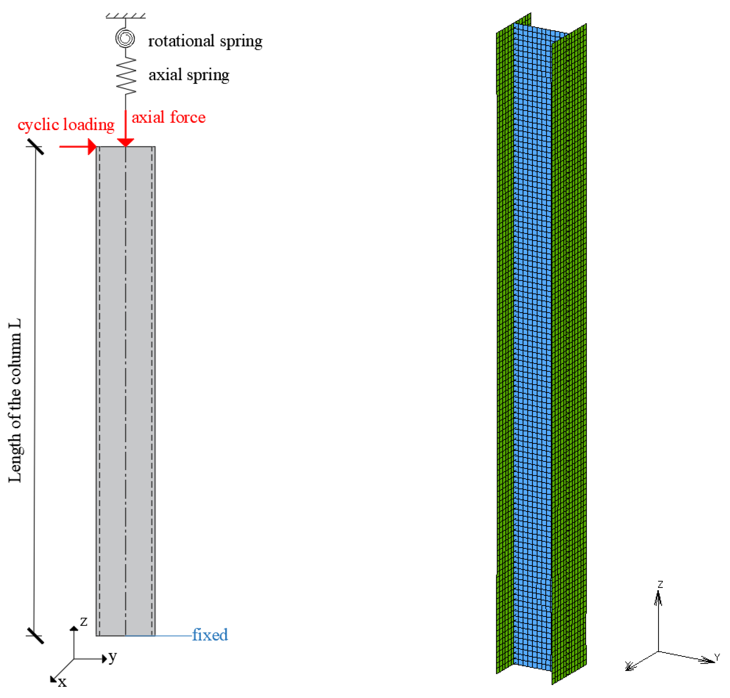
2.1. Numerical Models

Finite element analyses of steel columns have been conducted in this work to examine their post-fire behaviour under cyclic loading. The models were implemented within the general-purpose finite element code MSC Marc [37], using quadrilateral elements (element 75 of the library of MSC Marc 2018). This is a four-node, thick-shell element with global displacements and rotations as degrees of freedom. Bilinear interpolation is used for the coordinates, displacements, and rotations. The membrane strains are obtained from the displacement field and the curvatures from the rotation field. The transverse shear strains are calculated at the middle of the edges and interpolated to the integration points. Through this formulation, the element retains the proper rank and, hence, does not exhibit various kinds of spurious behaviour. Moreover, the locking phenomena are eliminated. In this way, a very efficient and simple element is obtained that exhibits correct behaviour in the limiting case of thin shells. A four-point Gaussian integration is chosen for the element in the plane of the shell and the eleven-point Simpson’s rule is used in the thickness direction. This large strain formulation for the nonlinear procedure is used in the analyses. This activates a formulation suitable for large strains, displacements, and rotations and the updated Lagrange framework is used.
At both the base and the top end of the column, rigid kinematic links are used to apply the boundary conditions. The central node of the cross-section (retained node) is tied with all the other nodes of the cross-section (tied nodes), using the RBE2 link of MSC Marc [37]. The tying includes all the degrees of freedom. Using this option, the boundary conditions are applied to the retained node.
The proposed finite element model represents an axially and rotationally restrained steel column (see Figure 1). While the column base was considered rigid, the effect of the flexibility of the column-beam connections at its top end is included in the model through the rotational spring. The spring is defined through the rotational restraint stiffness ratio αR (Equation (1)), which is the ratio of the rotational stiffness of the surrounding structure kR to the rotational stiffness of the column kR,C.
The effect of the axial restraint induced by the surrounding structure during the thermal loading was included in the numerical model through an axial spring [38,39,40]. This restraint appears when a heated column is part of a frame, and the columns of the same floor are not heated at exactly the same rate. When a column is heated, the ends of the beams that are connected to its top end will undergo a vertical movement due to its thermal expansion. If the columns at the other ends of the connected beams remain cool, the beams will undergo differential vertical movement of their ends and they will therefore exert a restraining force on the heated column, resisting its vertical expansion [38]. Only when an entire floor is heated at exactly the same rate, all the columns will escape the addition of a restraint force, since they will all thermally expand together, and no relative vertical movement will be present. The axial spring is defined through the axial restraint stiffness ratio αA, equal to the ratio of the axial stiffness of the surrounding structure kA to the axial stiffness of the column kA,C (see Equation (2)).
α R = k R k R , C   and   k R , C = 4 E C   I C L 0
α A = k A k A , C   and   k A , C = A C   ·   E C L 0
In Equations (1) and (2), AC and IC are the cross-sectional area and second moment of area of the restrained column, respectively, and EC is the Young’s modulus of the material at room temperature.
In the current study, S355JR [41] structural steel material is used. The yield stress and modulus of elasticity are 355 MPa and 210 GPa, respectively, at room temperature. For the heating stage, the material properties (reduction factors for yield stress, proportional limit, modulus of elasticity, and stress-strain relationship) are considered according to EN 2 January 1993 [12]. The post-fire properties (yield stress, elastic modulus, and ultimate stress) were considered according to [20]. In particular, the following reduction factors were adopted to determine the residual post-fire properties of structural steel:
f y T f y = { 1 T     600   ° C 1.504 T / 1200 600   ° C   <   T     900   ° C
f u T f y = { 1     T     600   ° C 1.208 T / 2900 600   ° C   <   T     900   ° C
E T E = { 1     T     600   ° C 1.431 T / 1400 600   ° C   <   T     900   ° C
where f y T , f u T , E T are the yield stress, the ultimate stress, and the modulus of elasticity at T °C and f y , f u   , E are the corresponding values at room temperature.
For the cyclic loading stage, the material constitutive relationships are based on a von Mises yield surface J2 plasticity [42], with the well-established combined isotropic/kinematic hardening law [43]. The Chaboche model combines isotropic hardening to describe the cyclic hardening, and nonlinear kinematic hardening to capture proper characteristics of cyclic plasticity. The nonlinear kinematic and isotropic hardening parameters defined in Equations (6) and (7) are:
X ˙ = [ C 1 R + k ( σ X ) γ Χ ] ε ˙ p l
where X is the back stress tensor representing the center of the yield surface in stress space, σ is the stress tensor, and εpl is the equivalent plastic strain. C and γ are two material constants, C is the translation rate of yield surface, and γ is the relaxation rate of yield surface translation as plastic deformation accumulates. The quantity R + k defines the size of the yield surface, and the initial conditions of cyclic hardening are k = σy and R = 0 (σy is the initial yield stress). The evolution equation for the variable R is described as follows:
R = R ( 1 e b ε p l )
where R and b are material constants. R represents the maximum change in size of yield surface and b is the rate at which size of yield surface changes as plastic deformation develops. In the current study, the material constants C, γ, R ,   and b are taken according to [44]. Specifically, the following values were adopted: C = 12.640 MPa, γ = 91, R = 70 MPa, and b = 2.
Aiming for a more realistic assessment of a column’s behaviour, initial imperfections are incorporated in the geometry of the finite element models. In particular, local web/flange and global out-of-pane imperfections were introduced, with magnitudes equal to d/250 and b/250 (where d = h - 2tf, b and h are the width and depth of the cross section and tf is the flange thickness) for the web and flange, respectively, and L/1500 for the global imperfection [45]. To incorporate the initial imperfections, the buckling eigenmodes were extracted and introduced as imperfections with a specific amplitude. For this purpose, the normalized buckling modes are multiplied by a scale factor, leading to the desired maximum amplitude, and the resulting buckled geometry is added to the initial coordinates of the FE model.

2.2. Numerical Analyses

The loading involves two different stages. During the first stage, the column is exposed to fire (including the heating and cooling phase), and the cyclic loading is applied during the second stage. Note that different boundary conditions and material models are required to accurately simulate the behaviour of columns during the separate stages. For this reason, two different analyses are conducted.
First, a thermal-structural analysis is conducted which includes both heating and cooling of the column. The second analysis reads as an initial condition of the output file of the first analysis. This includes all the results of the previous stage (i.e., the kinematic, strain, and stress tensors). Thus, in the second analysis, both the geometric damage (deformed shape of the column) and the material damage (plastic strains) are considered. During this mechanical analysis, the cyclic loading is applied while the axial load remains constant. The proper material properties are used, depending on the peak temperature during the first fire stage (according to Equations (3)–(5)).

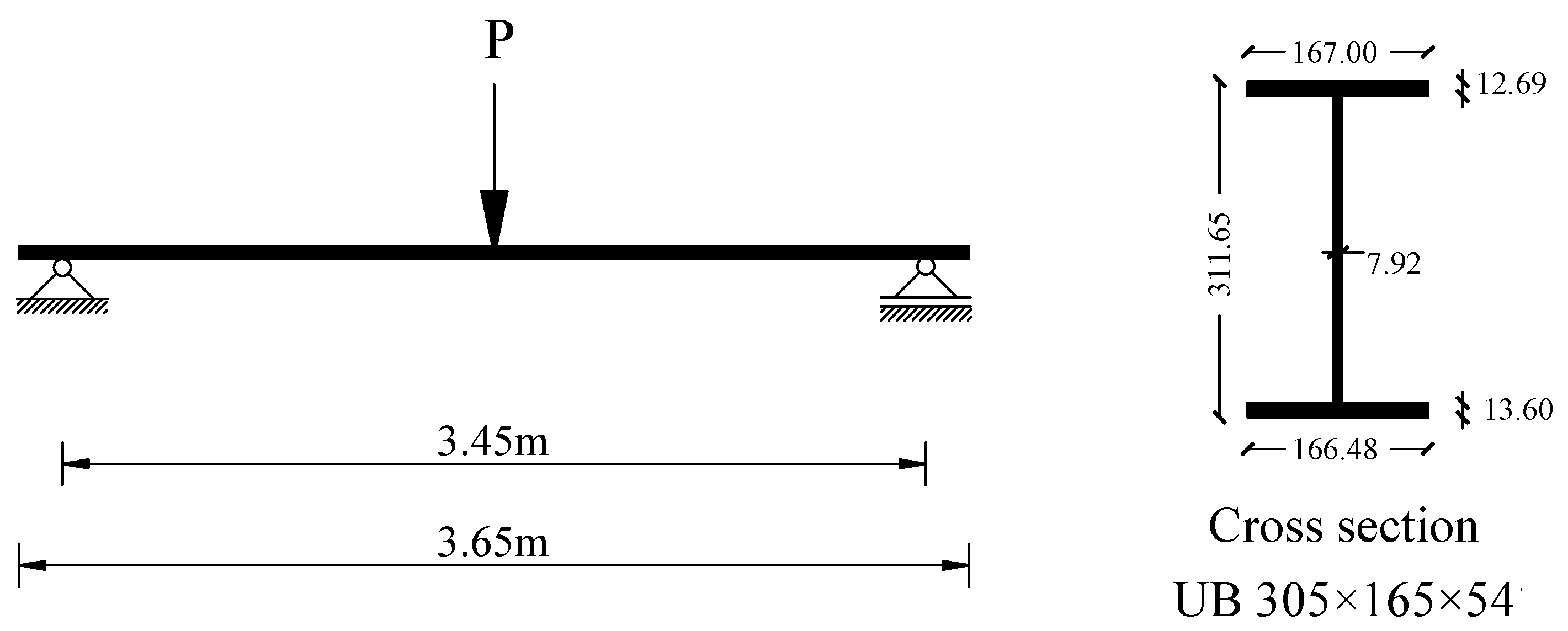
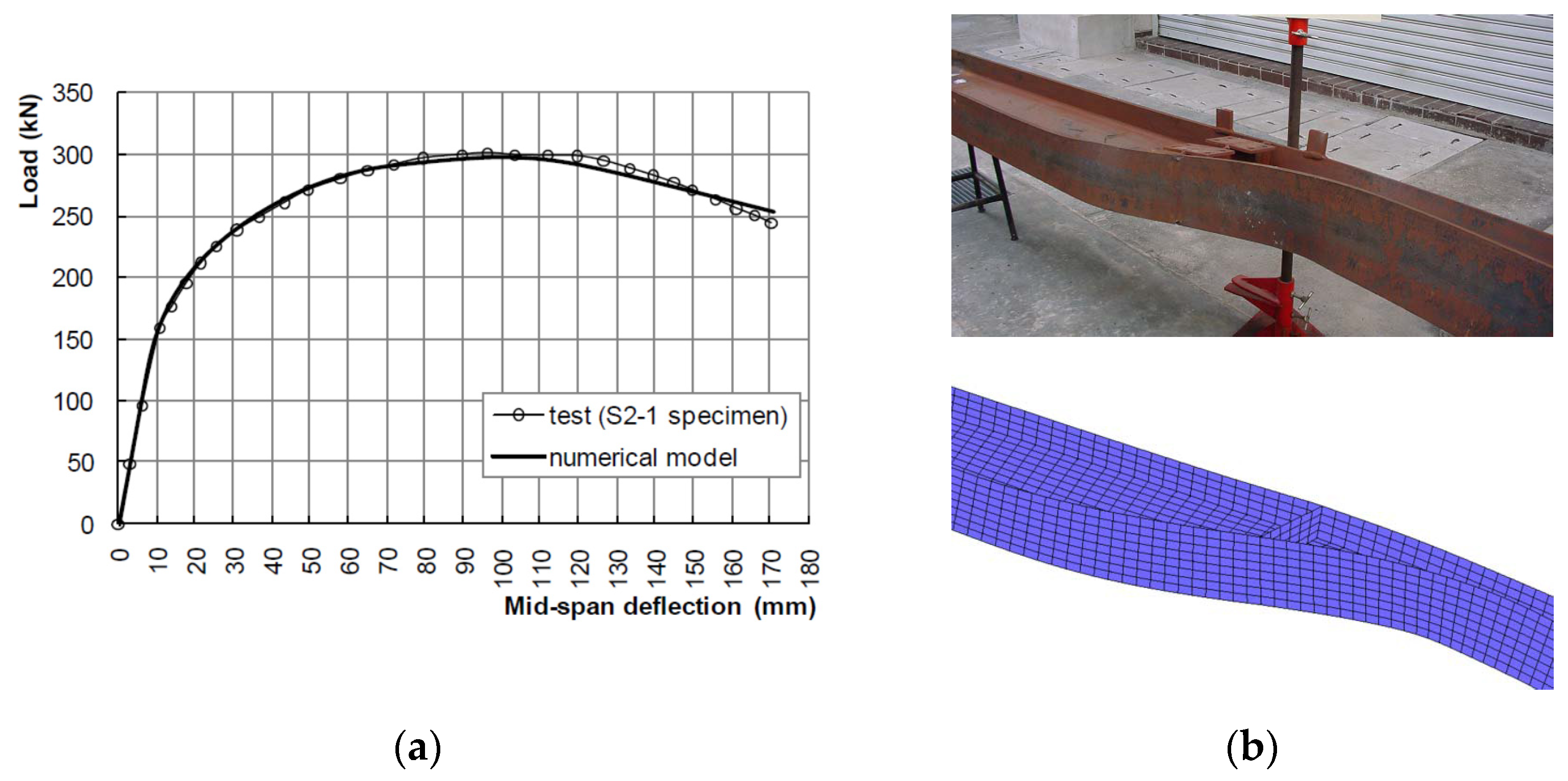
2.3. Finite Element Model Validation

The numerical model was validated against the experimental results that are presented in the study of Dharma and Tan [46]. For the needs of the validation, the simply supported steel I-beam of Figure 2 was chosen. The total length is equal to 3.65 m, while the distance between the supports is 3.45 m. Web stiffeners are used at the support and at mid-span, where the load is applied.
For validation purposes, the material properties at room temperature were considered according to the tensile tests of the experimental study. At elevated temperatures, the mechanical properties are according to the recommendations of EN 1993-1-2 [12] for carbon steel. The strain hardening was also included in the stress-strain relationship, according to Annex A of EN 1993-1-2 [12]. Preparatory numerical analyses and comparison with experimental results displayed significant strain-hardening of steel, even for temperatures equal to 400 °C. For this reason, the ultimate strength of steel (fu,θ) was taken equal to 1.6 fy,θ (fy,θ is the yield stress at elevated temperature) for temperature ranges between 20 °C and 400 °C. Although EN 1933-1-2 [12] suggests more conservative values for ultimate strength at elevated temperature (fu,θ = 1.25 fy,θ for T ≤ 300 °C), higher values are found in many experimental studies of the literature [47,48].
The beam is laterally restrained at the position of supports at both ends and at mid-span and, therefore, the development of plastic lateral-torsional buckling is possible at elevated temperatures. Additionally, local buckling of the upper flange may appear. For this reason, initial imperfections that correspond to both global and local buckling modes were included in the numerical model. The amplitude of the initial imperfections is taken equal to 0.5 mm for the buckling eigenmode, which is related to the lateral torsional buckling, and to 2 mm for the eigenmode, which is related to the local buckling of the upper flange. These values are in accordance with the measured initial imperfections that are presented in [46].
The numerical analysis has two different stages, following the test procedure described in [46]. During the first stage, the steel beam is heated under a heating rate of 7 °C/min until the desired temperature T is reached and the temperature is uniform along the beam. During the second stage, the temperature remains constant and the loading is applied at mid-span until failure.
Figure 3a presents the load-displacement curves obtained numerically and experimentally. A very good agreement is obtained, and the numerical model accurately predicts the load path. Slight differences in the unloading branch may be attributed to the uncertainties connected to the profile of the initial imperfections. Additionally, the failure mode that results from the numerical analysis is very close to the experimentally obtained mode, as presented in Figure 3b. In both cases, the failure is due to lateral-torsional buckling of the steel beam. Thus, it is considered that the numerical model accurately simulates the behaviour of the steel beam at elevated temperatures, and it may predict instabilities like lateral torsional buckling.

3. Columns with Simplified Boundary Conditions

During the heating and cooling stages, fixed boundary conditions (all the degrees of freedom were fixed except from the displacement z at the top end of the column) were considered for all the columns. The axial degree of freedom at the top end of the column is restrained by the axial spring, representing the effect of the surrounding structure. According to the literature [38,39], the restraint experienced by a heated column (Equation (2)) varies between very low values (e.g., 0.001) to very high values (e.g., 0.2). In this section, the axial restraint is considered equal to 0.1. During the cyclic loading stage, the columns are free to translate axially and rotate at their top end, while all the other degrees of freedom are fixed.
The cyclic loading protocol of Figure 4 has been employed in this study. The lateral load was coupled with the compressive axial load of constant magnitude. Four different levels of axial load ratios P/Py,20 = 0.1, 0.2, 0.3, and 0.4 were studied (where Py,20 is the axial plastic strength of the column). These loading ratios are typical for both interior and end steel columns of moment resisting frames. Lower values of axial load are typical for the interior columns, while the higher values are more typical in end columns [45]. Table 1 summarizes the parametric analyses that were conducted in this section.
The thermal-structural analysis, which is conducted to simulate the fire behaviour of columns, consists of four steps. During the first step, the column is at room temperature and the axial load is applied. The axial spring is activated at the onset of the second step and the heating is applied while the axial force remains constant. When the temperature reaches the maximum value, the third step starts, which includes the cooling phase. The axial spring is still active during this step and the axial force remains constant. When the column returns to room temperature, the axial spring is deactivated (fourth step). During the subsequent mechanical analysis, which is conducted to simulate the cyclic loading behaviour of columns, the axial spring is not active.

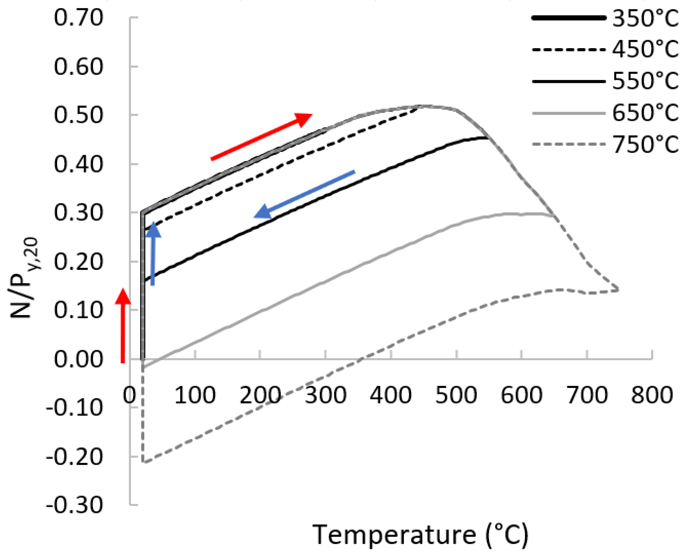
3.1. Behaviour during the Fire Stage

The axial forces developed in the HEB300_550 °C columns during the heating stage are presented in Figure 5. An increase in temperature results in thermal strain, which is partially prevented, generating thermal stresses and, therefore, the axial forces increase. The behaviour is linear elastic until the proportional limit is reached (482 °C, 397 °C, 378 °C, and 318 °C, for the columns HEB300_01_550 °C, HEB300_02_550 °C, HEB300_03_550 °C, and HEB300_04_550 °C). During the initial stages of heating, web and flange local buckling initiates. For further increases in temperature, the global out-of-plane displacements at the mid-height of the columns increase disproportionately and the buckling about the weak axis starts. At this point, the axial force takes its ultimate value and the temperature reaches its critical value (critical temperature). The critical temperatures are 509 °C, 493 °C, 447 °C, and 375 °C for the HEB300_01_550 °C, HEB300_02_550 °C, HEB300_03_550 °C, and HEB300_04_550 °C columns, respectively.
Figure 6 presents the axial forces in the HEB300_03 columns, during both heating and cooling stages. The unloading branch during the cooling stage depends on the axial restraint and subsequently on the spread of the fire. For example, if the fire is restricted to the left bay of the first story of the frame of Figure 7 (Scenario A of Figure 7a) during the cooling stage, the Beam 1B will undergo differential vertical movement of its ends, and therefore a restraining force will be exerted on the Column1B. In this case, the axial restraint of the column 1B is the same during both cooling and heating stages, and the axial force at the end of cooling stage (Figure 7c) is different from the initial force (before heating).
In the event of fire spread to the neighbour bays of the first story (Scenario B of Figure 7b), the behaviour of interior columns (e.g., Column 1B) will be different. While fire remains in the left bay, the restraint effect in Column 1B is active. As soon as the fire gradually spreads to the central and right bays, the neighbour columns (1C and 1D) will expand and contract, and the restraint effect will be gradually relieved. Finally, the axial force of Column 1B will return (approximately) to its initial value (Figure 7d).
In this section, the study focuses on interior columns, and it is assumed that the columns’ axial force returns to its initial value (Figure 6).
The magnitude of the maximum temperature (Tmax) during the heating stage affects the deformed shape of the column at the end of the cooling stage. If the maximum temperature (e.g., 350 °C) is less than the temperature that corresponds to the ultimate axial force (critical temperature equal to 447 °C for the HEB300_01 column), the column remains in the elastic branch and returns to its initial condition through the same path (Figure 6). In this case, there are no residual post fire displacements in the column. For this reason, the columns with Tmax = 350 °C, are not further studied. For maximum temperature beyond the critical temperature (e.g., 550 °C), the column enters a non-linear elastic branch (the stresses are larger than the proportional limit and less than the yield stress) and the unloading path that follows is non-linear (Figure 6). Moreover, the column is on the post-buckling stage and therefore it cannot return to the initial undeformed shape. Only part of the displacements that were developed during the heating stage are relieved, and the column remains in a deformed condition, which is the initial condition for the cyclic loading stage. The deformed shapes of HEB300_03 columns at the end of heating and cooling for different maximum temperature levels are presented in Figure 8. The results for the column HEB300_03_450 °C are omitted in this figure because the magnitude of the displacements is very small (maximum 0.9 mm). It is observed that the global flexural buckling mode about the weak axis is coupled with the local buckling of web and flanges, but as the maximum temperature increases, the global mode becomes dominant.
The behaviour of HEA340 columns is similar to the HEB300 columns. Local web and flange buckling initiates during the early stages of the heating stage and finally flexural buckling about the weak axis takes place. Also, the critical temperatures are almost identical (Table 2) because their radius of gyration about the weak axis is almost the same (75.8 mm and 74.6 mm, respectively, for the HEB300and HEA340 columns, respectively). Nevertheless, larger displacements are detected for the HEA340 columns (Figure 9), because of the larger web and flange slenderness ratios (see Table 1). The global and local out-of-plane displacements at the end of the cooling stage are summarized in Table 2 (the global displacements are recorded at the mid-height of the columns). Their magnitude increases significantly as the load level and maximum temperature increase. It is anticipated that the global displacements may lead to premature global buckling during the subsequent cyclic loading stage.
Emphasis is also placed on the base of the columns, where the plastic hinges are expected to be formed during the cyclic loading stage. Local buckling is critical because it may reduce the lateral restraint at column ends and trigger premature global instabilities [45]. Based on Figure 9, the flange local buckling waves are symmetric and antisymmetric with respect to the xz and yz planes, respectively. Their length is almost the same for both columns and their center is located at the same height from the base (1.25 d and 1.05 d for the HEB300 and HEA340, respectively). Two web local buckling waves appear at 0.45 d/1.1 d and 0.4 d/0.9 d from the base for the HEB300 and HEA340 columns, respectively. Note that the local buckling waves appear at the same locations for all the load levels and examined temperatures.

3.2. Behaviour during Cyclic Loading

The behaviour of the pre-damaged steel columns under cyclic loading is evaluated through several indicators. These include the overstrength factor ρ (ρ = Mmax/Mpl,20), the achieved rotation capacities θMpl,20, and θMmax, as they are defined on the first-cycle envelope curve of Figure 10.
Figure 11 depicts the first cycle envelope curves of the moment Mx (about the strong axis) versus the chord-rotation, at the base of the HEB300 columns and Table 3 summarises the results. The moment-rotation curves at both ends of the specimen were nearly identical due to the fixed-fixed boundary conditions, so the corresponding curves at the top end of columns are not included here. The results are compared with the case where the columns are not damaged. The behaviour of the HEB300 columns was slightly affected by damage (residual displacements) that was introduced by the heating stage, for maximum recorded temperatures 450 °C and 550 °C and for all loading levels. Differences are observed for Tmax ≥ 650 °C, which become more significant as the load level increases.
For the lowest loading level (P/Py,20 = 0.1) and Tmax = 650 °C, the reduction of the maximum moment of the first envelope curve was 7%, with respect to the undamaged column. This can be attributed to the reduced yield stress of steel (according to Equation (3) the reduction factor for the yield strength is 0.96) and the residual displacements. The maximum moment appears earlier for the damaged column (θMmax = 3% and 2% for the HEB300_01_undamged and HEB300_01_650 °C, respectively) and its rotational capacity (θMpl,20) is 10% reduced (Table 3). The reduction of the flexural capacity (i.e., the maximum deduced moment of the damaged column with respect to the undamaged one) is 16% for the HEB300_01_750 °C, while its rotation capacity is further reduced by 30% (Table 3).
To obtain further insight into the behaviour of columns, Figure 12a,b compare the out-of-plane displacements in the columns HEB300_01_undamaged, HEB300_01_650 °C, and HEB300_01_750 °C. The plastic hinge at the base of the columns was formed during the second cycle of the 1.0% drift amplitude, in all the columns. The local web and flange buckling occurred during the first cycle of the 3.0% drift amplitude for the undamaged column, and this led to flexural strength deterioration. In the damaged columns, the local buckling waves, which were introduced due to the heating/cooling, are amplified during the cyclic loading. Initially, the out-of-plane displacements grow slowly, but during the first cycle of the 2.0% drift amplitude they start to grow rapidly, launching flexural deterioration. Note that the center of both the local flange and web buckling coincide in the undamaged and damaged columns.
It is also observed that local buckling at the plastic hinge regions results in axial shortening of the columns, which increases rapidly as the local out-of-plane deformations become excessive (i.e., for drift amplitude larger than 3% (Figure 12c)). Moreover, the excessive deformations due to local buckling trigger lateral displacements in the plastic hinge regions and, subsequently, global out-of-plane displacements take place (Figure 12b). This was more obvious for the damaged columns and for drift amplitude larger than 3% and 2% for the HEB300_01_650 °C and HEB300_01_750 °C, respectively. Figure 12b depicts the evolution of the global out-of-plane displacements at selected drift amplitudes (first-cycle envelope curve). Their magnitude was measured at two different locations along the height of the member (at L/3 and 2L/3 from the column base). It is also interesting to note that the global out-of-plane displacements that appear at the end of the cooling stage did not trigger any global instability. On the contrary, they are reverted back to zero and gradually they grow in the opposite direction (Figure 13). Thus, the failure is due to the plastic hinge formulation and the local buckling mechanism that triggers the global out-of-plane displacements.
The same failure mechanism was detected for all load levels (P/Py,20 = 0.2, 0.3, and 0.4). The history of the out-of-plane displacements at the center of the web and flange local buckling waves, as well the global out-of-plane displacements for the load level P/Py,20 = 0.4, are provided in Figure 14. The only case study where the failure can be attributed to buckling about the weak axis is the damaged column HEB300_04_750 °C. In this case, the maximum moment Mx is less than the full plastic moment (which is 0.88 Mpl,20, based on the reduction factor of the yield stress, according to Equation (3)). The plastic hinges were not fully formed, and the local web and flange buckling appears during the first cycle of drift amplitude equal to 0.75%. Plastic deformations were evident at the end of the cooling stage at the crest of the local buckling waves. The out-of-plane displacements at L/3 and 2L/3 of the column height grow quickly for drift amplitudes larger than 1%, and the dominant failure is buckling about the weak axis.
Figure 15 displays the first cycle envelope curves of the moment Mx (about the strong axis) versus the chord-rotation, at the base of the HEA340 columns and Table 4 summarises the results. It is observed that plastic hinges are not formed in all columns (Figure 16).
For the loading level P/Py = 0.1, all the columns fail due to the formulation of plastic hinges at the base and their top end, and the local buckling mechanism that triggers global out-of-plane displacements. For higher loading levels, the behaviour depends on the maximum temperature recorded during the fire stage. For the columns where the flexural strength is less than the full plastic moment of the cross section, although the plastic hinges are not formed, the excessive local buckling deformations trigger the global out-of-plane displacements in the columns again. The residual global out-of-plane displacements (post fire displacements) are reverted back to zero and they grow in the opposite direction (Figure 17) very quickly. Thus, the columns fail due to coupled local and global instabilities. Note that when the plastic hinge mechanism is formed, the excessive global out-of-plane displacements are prevented.
The only case study where the failure can be attributed to buckling about the weak axis is the heavily damaged column HEA340_04_750 °C. In this case, the plastic hinges were not fully formed, the global out-of-plane displacements grow fast for drift amplitude larger than 0.75%, and the dominant failure is buckling about the weak axis.

4. Column with Realistic Boundary Conditions

The main objective of this section is to study the behaviour of columns under cyclic loading that has been damaged by fire, using realistic boundary conditions. For this purpose, the frame of Figure 18, which has been designed against earthquakes (details are included in [49]), is used. To reduce the computational cost, the details of the connections were not included in the numerical model and the beams were considered welded to the columns. A primary analysis highlighted the importance of column web stiffeners, which are usually used in the beam-to-column connections of seismic resisting frames; for this reason, they were included in the model (Figure 19).
The scenarios of Figure 18 are examined. The fire is represented by the ISO fire curve, as defined in Eurocodes [12,50]. For the first scenario (Scenario A), the fire takes place at the left bay of the first story of the frame. For the second scenario, the fire starts from the left bay and when the temperature of the structural members returns to its ambient value, the fire expands to the next bay; in this way, it gradually spreads to the right bay. The temperature of the beams and columns is calculated according to the guidelines of EN 1993-1-2 [12], and it is uniform in the cross-section and along the length of all the structural members. The maximum temperatures for the columns and beams are 750 °C and 780 °C, respectively, for both scenarios. Both beams and columns are protected against fire using vermiculite cement (properties according to [51]) of 10 mm thickness. Preparatory analyses were conducted for the calculation of the critical temperature of columns, which was found to be equal to 640 °C.
In this section, the fire behaviour of the columns was evaluated through thermal-structural analyses of the seismic resistant frame. In this way, the complicated interaction between the columns and the surrounding structure during the fire stage was considered. The numerical model that was used to evaluate the behaviour of columns for the cyclic loading includes only the examined column; the surrounding structure is not included. Its effect is considered through the rotational spring at the top end of the columns. The boundary conditions for the isolated columns are the following: the bottom of the column is fixed while the top end is free to translate in the y- and z-directions, the rotational degree of freedom about the x-axis is controlled by the rotational spring, and the other degrees of freedom are fixed. The rotational stiffness ratio aR (Equation (1)) was calculated numerically equal to 0.45–048 for all the heated columns.

4.1. Behaviour during the Fire Stage

The axial forces for all heated columns during the fire stage are presented in Figure 20, for both the examined scenarios. A redistribution of forces takes place during fire. When the fire takes place at the left bay (Scenario A), the axial force ratio at the end of the cooling stage is different from its initial value (before heating) for both heated columns. When the fire spreads to the neighbour bays (Scenario B), the axial force returns approximately to its initial value for the interior columns (1B and 1C).
The post-fire deformed shape of the left bay of the frame is presented in Figure 21 (Scenario A). It is observed that the beam is severely damaged, while the columns are slightly damaged. Small web and flange out-of-plane displacements are detected for the heated columns and the global out-of-plane displacements are minor as well (Figure 22). As demonstrated in the same figures, residual (in-plane) global displacements appear in both columns for Scenario A. Their distribution is almost triangular along the height of the columns and the maximum value appears at their top end. These displacements appear due to the thermal expansion/contraction of the connected beam. During heating, a lateral force acts at the top end of the columns due to the restrained thermal expansion of the beam, which is connected at its top end. This force is reversed during cooling, but it is not eliminated, and the columns do not return to their initial position [8].
When the fire spreads at the neighbour bays (Scenario B), the post-fire deformed shape of column 1B is different. The global in-plane displacements are small, and the column remains “straight” at the end of the cooling stage. This is attributed to the fact that the connected beams at the top end of the column are heated to the same maximum temperature. For this reason, the forces that act on the columns are equal and opposite and they are balanced. Moreover, no significant residual web and flange out-of-plane deformations are detected (Figure 22). The post-fire deformed shapes of columns 1C and 1D are antisymmetric to columns 1B and 1A, respectively, and for this reason the results are omitted.

4.2. Behaviour during Cyclic Loading

The first cycle envelope curves for the moment Mx at the base and top end of the columns are presented in Figure 23. The different behaviour at the ends of the column is due to the flexible support at the top end. In the case of the undamaged column, a plastic hinge is first formed at its base and the maximum moment appears for a chord rotation equal to 2%. Once the plastic hinge is formed due to force redistribution, the flexural demand at the top end of the column increases and the maximum moment appears for a chord rotation equal to 4%.
The flexural capacity of all the columns is reduced with respect to the undamaged column. The reduction of the maximum moment of the first envelope curve was almost 14% (Table 5); this is mainly attributed to the reduced yield stress of steel (according to Equation (3), the reduction factor for the yield strength is 0.88). The combination of the residual displacements and deteriorated mechanical properties strongly affected their rotational capacity (a reduction of 45% is detected for Column A for Scenario A, according to Table 5). It was also observed that flexural deterioration is detected earlier for the damaged columns (reduced chord-rotation at the maximum moment). This may affect the global behaviour of the frame during an earthquake, by increasing the story drift demands. Furthermore, it triggers the earlier local buckling and the subsequent flexural deterioration at the top end, and this may affect the global behaviour of the frame by promoting the soft-story mechanism. It is concluded that although the columns can survive at high temperatures (750 °C) without significant damage, they are more vulnerable during an upcoming earthquake.

5. Summary and Conclusions

The post-fire behaviour of steel columns under cyclic loading was studied numerically. The sophisticated numerical model includes an axial and a rotational spring to simulate the effect of the surrounding structure. The problem was solved in two successive analyses. First, a thermomechanical analysis was conducted to simulate the behaviour of the columns during a fire (heating and cooling). The post-fire behaviour of the damaged columns under cyclic loading was simulated in the second analysis. This analysis reads the output of the first one as an initial condition, and the relevant material properties were used (depending on the maximum temperature recorded during the first analysis).
First, the behaviour of the columns was studied, using simplified boundary conditions, and the surrounding structure was not included in the model. Parametric analyses were conducted with respect to the maximum temperature recorded during the heating stage and the axial load level. The following conclusions were drawn:
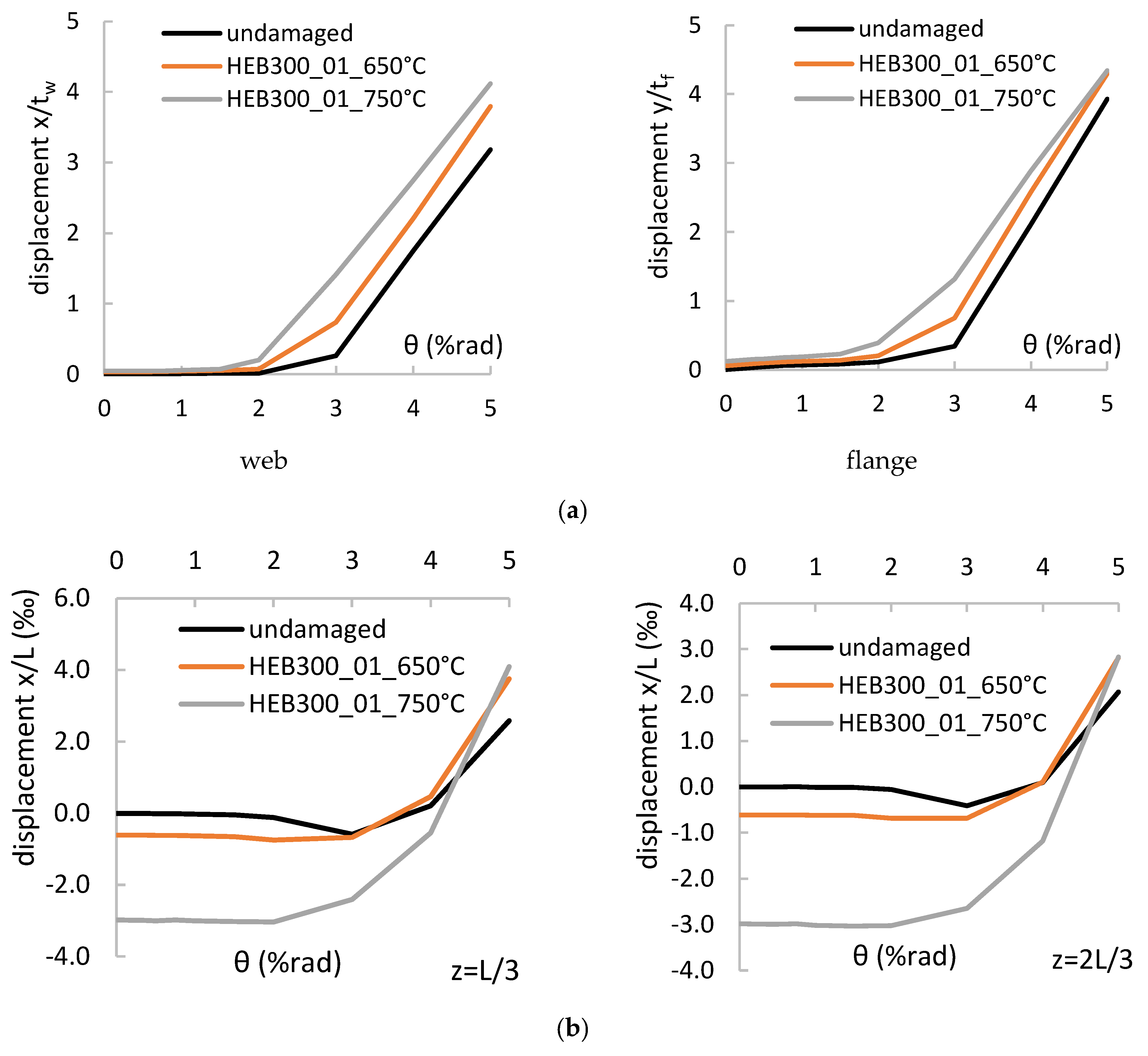
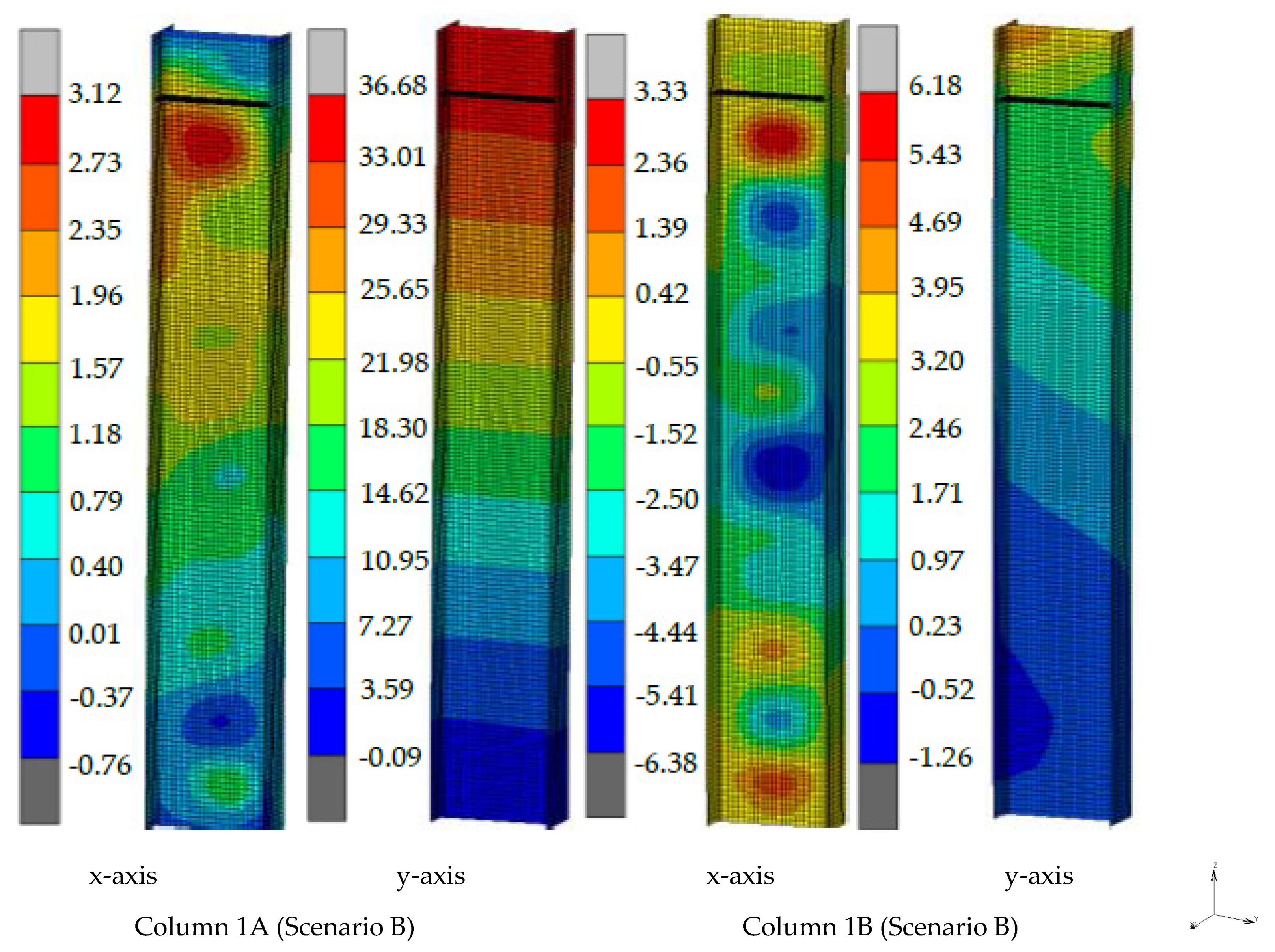
  • At the end of the fire stage, global out-of-plane displacements are coupled with local buckling of web and flanges. Their magnitude escalates with the load level and the maximum recorded temperature.
  • Slight residual local displacements (approximately 1 mm) did not affect the behaviour of the columns during the cyclic loading for maximum recorded temperatures less or equal to 550 °C.
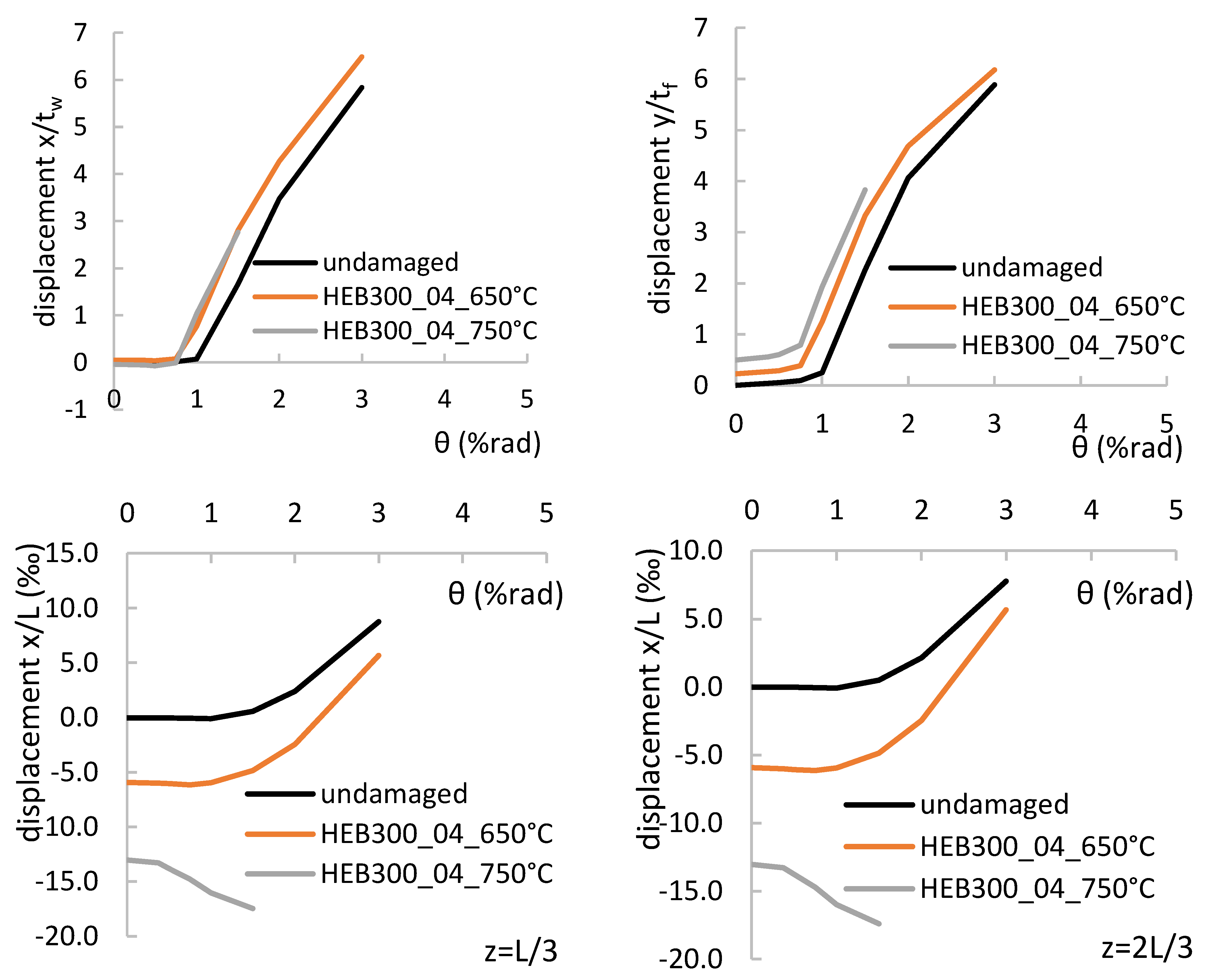
  • Larger amplitude of local out-of-pane displacements near their base may affect their cyclic behaviour by triggering premature local buckling phenomena and subsequent loss of the flexural capacity. This was more obvious as the load level increases and for temperature levels more than 550 °C.
  • The global out-of-plane residual displacements (less than 1% L) did not affect the cyclic behaviour of the columns and did not activate any global instabilities.
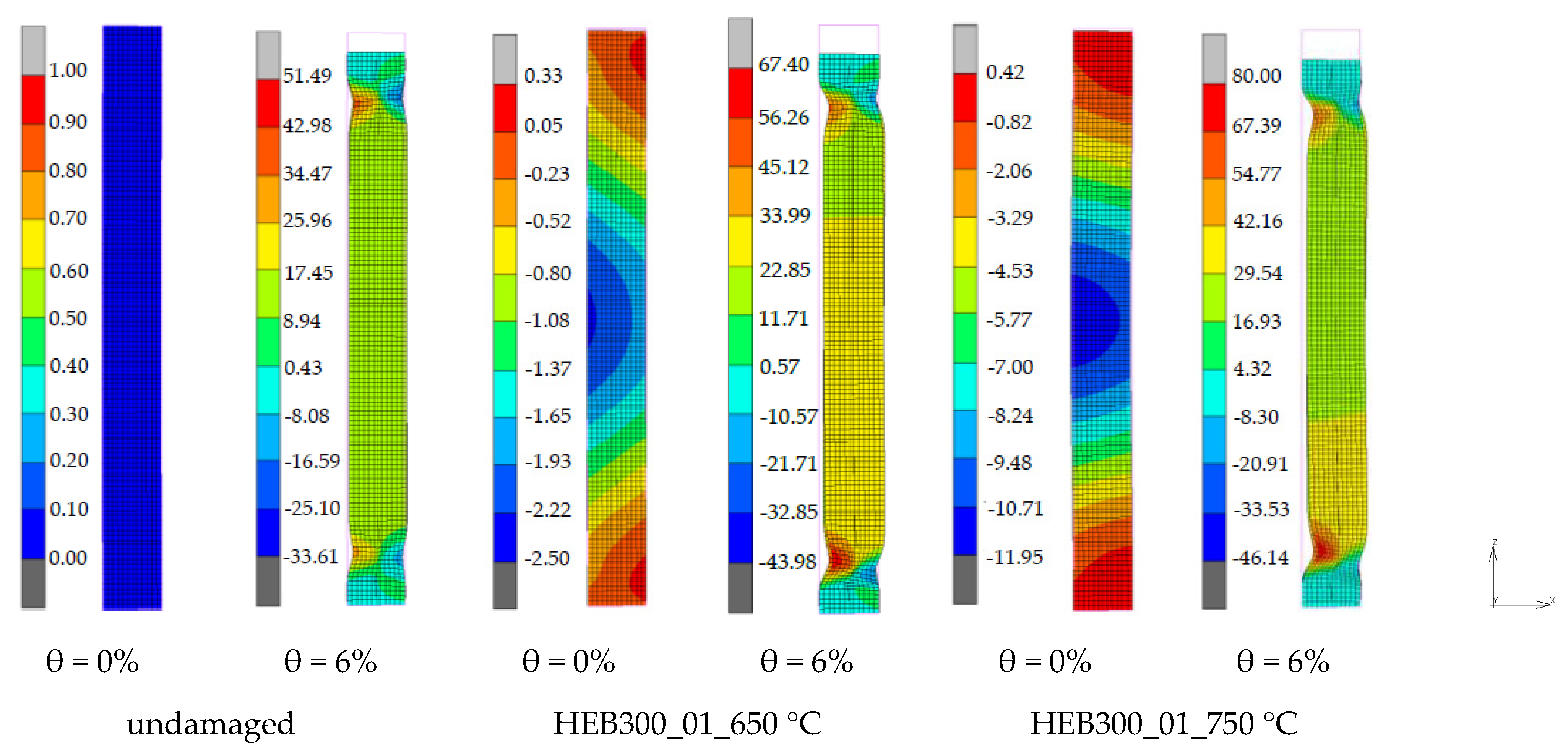
  • The failure of the columns was mainly attributed to the plastic hinge formulation and the local buckling mechanism which triggers global out-of-plane displacements.
  • Another failure mode was also detected which couples local and global instabilities. For these columns, the maximum moment is less than the full plastic moment of the cross section, and the plastic hinges are not formed. Nevertheless, the excessive local buckling deformations trigger global instability about the weak axis.
  • Only the heavily damaged columns (magnitude of global out-of-plane displacements more than 1% L) failed due to lateral buckling.
Aiming to get more realistic results, the complicated interaction between the heated columns and the surrounding structure was considered. For this reason, the fire behaviour of a seismic resistant frame was simulated. The analysis, which is conducted to simulate the cyclic loading behaviour, includes only the examined columns; the surrounding structure was not included. Its effect was considered through the rotational spring at the top end of the columns. The conclusions were the following:
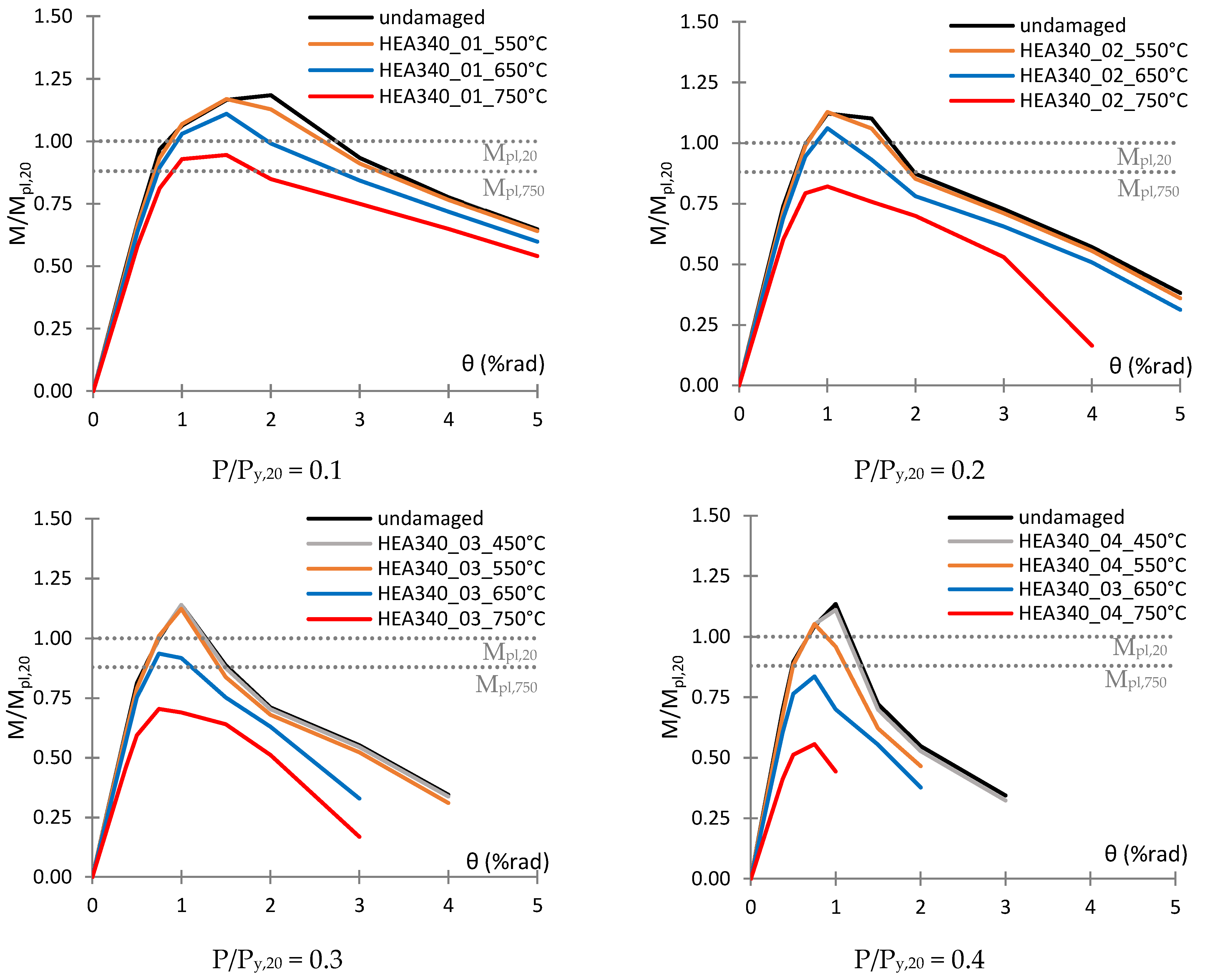
  • During the cyclic loading, the flexural capacity of all the columns was reduced, mainly due to the deterioration of material properties.
  • The rotation capacity of the damaged columns is reduced due to both the residual displacements and the deterioration of the mechanical properties.
  • The flexural deterioration is detected earlier for the damaged columns, and this triggers earlier local buckling and subsequent flexural deterioration at the top end.
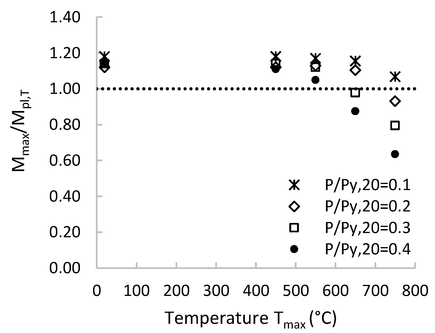
  • Although the fire-damaged columns can survive at high temperatures (750 °C) without significant damage, their behaviour will be more vulnerable during an upcoming earthquake.
Further research is needed to better understand the post-fire behaviour of steel structures under earthquake. Full scale tests on steel columns are needed, to genuinely validate the numerical models used in this paper. More experimental and numerical work is also needed to investigate the seismic vulnerability of steel frames after fire events and propose guidelines for their reuse.

Author Contributions

Conceptualization, D.P. and C.M.; methodology, T.K. and D.P.; software, D.P.; validation, D.P.; formal analysis, D.P.; investigation, D.P.; resources, T.K., D.P. and C.M.; data curation, D.P.; writing—original draft preparation, D.P.; writing—review and editing, D.P. and T.K.; visualization, D.P., T.K. and C.M.; supervision, T.K.; project administration, T.K.; funding acquisition, T.K., D.P. and C.M. All authors have read and agreed to the published version of the manuscript.

Funding

This research is co-financed by Greece and the European Union (European Social Fund- ESF) through the Operational Programme “Human Resources Development, Education and Lifelong Learning 2014–2020” in the context of the project “Seismic behaviour of steel structures after fire and reuse criteria” (MIS 5047150).

Informed Consent Statement

Not applicable.

Data Availability Statement

Not applicable.

Conflicts of Interest

The authors declare no conflict of interest.

References

  1. Karavasilis, T.; Bazeos, N.; Beskos, D. Maximum displacement profiles for the performance based seismic design of plane steel moment resisting frames. Eng. Struct. 2006, 28, 9–22. [Google Scholar] [CrossRef]
  2. Karavasilis, T.; Bazeos, N.; Beskos, D. A New Seismic Design Method for Steel Structures. Adv. Struct. 2010, 13, 161–171. [Google Scholar]
  3. Kariniotakis, K.; Karavasilis, T. Limits for the interstorey drift sensitivity coefficient θ of steel MRFs with viscous dampers designed according to Eurocode 8. Soil Dyn. Earthq. Eng. 2019, 117, 203–215. [Google Scholar] [CrossRef]
  4. Dimopoulos, A.; Karavasilis, T.; Vasdravellis, G.; Uy, B. Seismic design, modelling and assessment of self-centering steel frames using post-tensioned connections with web hourglass shape pins. Bull. Earthq. Eng. 2013, 11, 1797–1816. [Google Scholar] [CrossRef]
  5. Beer, Μ.; Kougioumtzoglou, Ι.A.; Patelli, Ε.; Au, S.-K. Encyclopedia of Earthquake Engineering; Springer: Berlin/Heidelberg, Germany, 2015. [Google Scholar]
  6. Wang, Y.; Burgess, Ι.; Wald, F.; Gillie, M. Performance-Based Fire Engineering of Structures; CRC Press: Boca Raton, FL, USA, 2017. [Google Scholar]
  7. Franssen, J.-M.; Kodur, V.; Zaharia, R. Designing Steel Structures for Fire Safety; CRC Press: Boca Raton, FL, USA, 2009. [Google Scholar]
  8. Wang, Y.C. Steel and Composite Structures, Behaviour and Design for Fire Safety; Spon Press: London, UK, 2002. [Google Scholar]
  9. Porcari, G.F.; Zalok, E.; Mekky, W. Fire induced progressive collapse of steel building structures: A review of the mechanisms. Eng. Struct. 2015, 82, 261–267. [Google Scholar] [CrossRef]
  10. Wald, F.; da Silva, L.S.; Moore, D.B.; Lennon, T.; Chladná, M.; Santiago, A.; Beneš, M.; Borges, L. Experimental behaviour of a steel structure under natural fire. Fire Saf. J. 2006, 41, 509–522. [Google Scholar] [CrossRef]
  11. EN 1991-1-2; Eurocode 1: Actions on Structures Exposed to Fire—Part 1–2. General Actions—Structural Fire Design. European Committee for Standardization: Brussels, Belgium, 2002.
  12. EN 1993-1-2; Eurocode 3: Design of Steel Structures—Part 1–2. General Rules—Structural Fire Design. European Committee for Standardization: Brussels, Belgium, 2005.
  13. SCI. Structural Fire Engineering. In Investigation of Broadgate Phase 8 Fire; The Steel Construction Institute: Ascot, UK, 1991. [Google Scholar]
  14. Outinen, J.; Makelainen, P. Mechanical properties of structural steel at elevated temperatures and after cooling down. Fire Mater. 2004, 28, 237–251. [Google Scholar] [CrossRef]
  15. Tao, Z.; Wang, X.Q.; Uy, B. Stress-strain curves of structural and reinforcing steel after exposure to elevated temperatures. J. Mater. Civ. Eng. 2013, 9, 1306–1316. [Google Scholar] [CrossRef]
  16. Lee, J.; Engelhardt, M.D.; Taleff, E.M. Mechanical properties of ASTM A992 steel after fire. Eng. J. 2012, 49, 33–44. [Google Scholar]
  17. BS 5950-8; Structural Use of Steelwork in Building, Part 8: Code of Practice for Fire Resistant Design. BS Institution: London, UK, 2003.
  18. Li, G.Q.; Jiang, S.C.; Yin, Y.Z.; Chen, A.K.; Li, M.F. Experimental Studies on the Properties of Constructional Steel at Elevated Temperatures. J. Struct. Eng. 2003, 129, 1717–1721. [Google Scholar] [CrossRef]
  19. Kirby, B.R.; Preston, R.R. High temperature properties of hot-rolled, structural steels for use in fire engineering design studies. Fire Saf. J. 1988, 13, 27–37. [Google Scholar] [CrossRef]
  20. Maraveas, C.; Fasoulakis, Z.; Tsavdaridis, K.D. Post-fire assessment and reinstatement of steel structures. J. Struct. Fire Eng. 2017, 8, 181–201. [Google Scholar] [CrossRef]
  21. Tide, R.H. Integrity of structural steel after exposure to fire. Eng. J. AISC 1998, 35, 26–38. [Google Scholar]
  22. Smith, C.I.; Kirby, B.R.; Lapwood, D.G.; Cole, K.J.; Cunningham, A.P.; Preston, R.R. The reinstatement of fire damaged steel framed structures. Fire Saf. J. 1981, 4, 21–62. [Google Scholar] [CrossRef]
  23. Kirby, B.R.; Lapwood, D.G.; Thompson, G. The Reinstatement of Fire Damaged Steel and Iron Framed Structures; British Steel Corporation Swinden Laboratories: Rotherham, UK, 1986. [Google Scholar]
  24. Lou, G.B.; Zhu, M.C.; Li, M.; Zhang, C.; Li, G.Q. Experimental research on slip-resistant bolted connections after fire. J. Constr. Steel Res. 2015, 104, 1–8. [Google Scholar] [CrossRef]
  25. Yu, L. Behavior of Bolted Connections during and after a Fire. Ph.D. Thesis, University of Texas, Austin, TX, USA, 2006. [Google Scholar]
  26. Liu, H.; Tan, Z.; Chen, Z.; Liu, Z.; Liu, D. Experimental Study on Residual Mechanical Properties of Bolt-Sphere Joints After a Fire. Int. J. Steel Struct. 2018, 18, 802–820. [Google Scholar] [CrossRef]
  27. Liu, H.; Liu, D.; Chen, Z.; Yu, Y. Post-fire residual slip resistance and shear capacity of high-strength bolted connection. J. Constr. Steel Res. 2017, 138, 65–71. [Google Scholar] [CrossRef]
  28. Zhang, G.; Zhu, M.-C.; Kodur, V.; Li, G.-Q. Behavior of welded connections after exposure to elevated temperature. J. Constr. Steel Res. 2017, 130, 88–95. [Google Scholar] [CrossRef]
  29. Liu, H.; Liao, X.; Chen, Z.; Huang, S.-S. Post-fire residual mechanical properties of steel butt weld—Experimental study. J. Constr. Steel Res. 2017, 129, 156–162. [Google Scholar] [CrossRef]
  30. Zhu, M.-C.; Li, G.-Q. Behavior of beam-to-column welded connections in steel structures after fire. Procedia Eng. 2017, 210, 551–556. [Google Scholar] [CrossRef]
  31. Rodrigues, D.M.; Leitão, C.; Balakrishnan, M.; Craveiro, H.D.; Santiago, A. Tensile properties of S355 butt welds after exposure to high temperatures. Constr. Build. Mater. 2021, 302, 124374. [Google Scholar] [CrossRef]
  32. Sagiroglu, M. Experimental evaluation of the post-fire behavior of steel T-component in the beam-to-column connection. Fire Saf. J. 2018, 96, 153–164. [Google Scholar] [CrossRef]
  33. Molkens, T.; Rossi, B. Reliability-based structural response of single-bay steel frames in case of fire and in post-fire conditions. Struct. Saf. 2021, 93, 102132. [Google Scholar] [CrossRef]
  34. He, K.; Chen, Y.; Han, S. Experimental investigation of square stainless steel tubular stub columns after elevated temperatures. J. Constr. Steel Res. 2019, 159, 397–414. [Google Scholar] [CrossRef]
  35. EN 1998-1-1; Eurocode 8: Design of Structures for Earthquake Resistance—Part 1. General Rules Seismic Actions and Rules for Buildings. European Committee for Standardization: Brussels, Belgium, 2004.
  36. Quayyum, S.; Hassan, T. Seismic Performance of a Fire-Exposed Moment-Resisting Frame. J. Struct. Eng. 2018, 144, 04018206. [Google Scholar] [CrossRef]
  37. MSC Software Corp. MSC MARC v. 2018, Theory and User Information; MSC Software Corp.: Santa Ana, CA, USA, 2018. [Google Scholar]
  38. Shepherd, P.G.; Burgess, I.W. On the buckling of axially restrained steel columns in fire. Eng. Struct. 2011, 33, 2832–2838. [Google Scholar] [CrossRef] [Green Version]
  39. Tan, K.H.; Yuan, W.F. Buckling of elastically restrained steel columns under longitudinal non-uniform temperature distribution. J. Constr. Steel Res. 2008, 64, 51–61. [Google Scholar]
  40. Pournaghshband, A.; Afshan, S.; Foster, A.S.J. Structural fire performance of axially and rotationally restrained stainless steel columns. Thin Walled Struct. 2019, 137, 561–572. [Google Scholar] [CrossRef]
  41. EN 10025–2:2019; Hot Rolled Products of Structural Steels, Technical Delivery Conditions for Non-Alloy Structural Steels. European Committee for Standardization: Brussels, Belgium, 2019.
  42. Von Mises, R. Mechanik der festen Körper im plastischdeformablen Zustand. Nachrichten von der Gesellschaft der Wissenschaften zu Göttingen. Math. Phys. Kl. 1913, 1, 582–592. [Google Scholar]
  43. Lemaitre, J.; Chaboche, J.L. Mechanics of Solid Materials; Cambridge University Press: Cambridge, UK, 1990. [Google Scholar]
  44. Mohabeddine, A.; Koudri, Y.W.; Correia, J.A.F.O.; Castro, J.M. Rotation capacity of steel members for the seismic assessment of steel buildings. Eng. Struct. 2021, 244, 112760. [Google Scholar] [CrossRef]
  45. Elkady, A.; Lignos, D. Improved Seismic Design and Nonlinear Modeling Recommendations for Wide-Flange Steel Columns. J. Struct. Eng. 2018, 144, 04018162. [Google Scholar] [CrossRef]
  46. Dharma, R.; Tan, K.H. Rotational capacity of steel I-beams under fire conditions Part I: Experimental study. Eng. Struct. 2007, 29, 2391–2402. [Google Scholar] [CrossRef]
  47. Poh, K.W. Stress-strain temperature relationship for structural steel. J. Mater. Civil Eng. 2001, 13, 371–379. [Google Scholar] [CrossRef]
  48. Kodur, V.; Dwaikat, M. Response of steel beam-columns exposed to fire. Eng. Struct. 2009, 31, 369–379. [Google Scholar] [CrossRef]
  49. Pantousa, D.; Karavasilis, T. Numerical Assessment of the Fire Behavior of Steel Posttensioned Moment-Resisting Frames. J. Struct. Eng. 2020, 146, 04020032. [Google Scholar] [CrossRef]
  50. EN 1990; Basis of Structural Design. European Committee for Standardization: Brussels, Belgium, 2002.
  51. Cadorin, J.; Franssen, J. A tool to design steel elements submitted to compartment fires—Ozone v2. Part 1: Pre-and post-flashover compartment fire model. Fire Saf. J. 2003, 38, 395–427. [Google Scholar] [CrossRef]
Figure 1. The axially and rotationally restrained steel column and the numerical model.
Buildings 12 00288 g001
Figure 2. The structural system and the cross section (dimensions of the cross section in mm).
Buildings 12 00288 g002
Figure 3. (a) Comparison of the numerical analysis results with the test results for the specimen S2-1 at 415 °C; (b) deformed shape of the steel beam at failure.
Buildings 12 00288 g003
Figure 4. The cyclic loading protocol.
Buildings 12 00288 g004
Figure 5. Behaviour of HEB300_550 °C columns during the fire stage. (a) Axial forces; (b) Global out-of-plane displacements (x-axis) at mid-height of the column.
Buildings 12 00288 g005
Figure 6. Axial forces in the HEB300_03 columns during heating and cooling.
Buildings 12 00288 g006
Figure 7. Fire scenarios and axial forces in Column 1B. (a) Fire scenario A; (b) Fire scenario B; (c) Dimensionless axial ratio for the Scenario A; (d) Dimensionless axial ratio for the Scenario B.
Buildings 12 00288 g007
Figure 8. Deformed shape and displacement field (in mm) at the end of heating and cooling for the HEB300_03 columns. (a) End of heating phase; (b) End of cooling phase.
Buildings 12 00288 g008
Figure 9. Displacement field at the end of the cooling stage, near the base of the HEB300_03_650 °C and HEA340_03_650 °C columns.
Buildings 12 00288 g009
Figure 10. The first cycle envelope curve.
Buildings 12 00288 g010
Figure 11. First cycle envelope curves for the moment Mx at the base of the HEB300 columns.
Buildings 12 00288 g011
Figure 12. First cycle envelope curves of: (a) the normalized out-of-plane displacements at the center of local buckles, (b) the global out-of-plane displacements for the HEB300_01 columns, and (c) the normalized axial shortening of HEB300_01 columns.
Buildings 12 00288 g012aBuildings 12 00288 g012b
Figure 13. Deformed shape of the HEB300_01 columns at the begging of cyclic loading (θ = 0%) and for the θ = 6% chord rotation.
Buildings 12 00288 g013
Figure 14. Normalized global out-of-plane displacements for the HEB300_04 columns (first cycle envelope curves).
Buildings 12 00288 g014
Figure 15. First cycle envelope curves for the moment Mx at the base of the HEA340 columns.
Buildings 12 00288 g015
Figure 16. Overstrength factor considering the degradation of yield strength.
Buildings 12 00288 g016
Figure 17. Normalized global out-of-plane displacements for the HEA340 columns (first cycle envelopes).
Buildings 12 00288 g017
Figure 18. The seismic resistant frame and the fire scenarios.
Buildings 12 00288 g018
Figure 19. Detail of beam-column connection with web stiffeners.
Buildings 12 00288 g019
Figure 20. Normalized axial forces for the heated columns during fire.
Buildings 12 00288 g020
Figure 21. Deformed shape of the left frame of the first story (scenario A) and the x-displacement field (in mm).
Buildings 12 00288 g021
Figure 22. Displacement field (in mm) and deformed configuration of the heated columns.
Buildings 12 00288 g022aBuildings 12 00288 g022b
Figure 23. First cycle envelope curves for the moment Mx at the base and top end of the heated columns.
Buildings 12 00288 g023
Table 1. Columns with simplified boundary conditions.
Case StudyCross
Section
Length (m)b/2tfh/twP/Py,20Class at Room Temp.Class at High Temp.aAaRMaximum Temperature (°C)
HEB300_01_TmaxHEB30040007.9240.1110.1fixed350–750
HEB300_02_Tmax0.2110.1fixed350–750
HEB300_03_Tmax0.3110.1fixed350–750
HEB300_04_Tmax0.4110.1fixed350–750
HEA340_01_TmaxHEA34040009.1310.1130.1fixed350–750
HEA340_02_Tmax0.2130.1fixed350–750
HEA340_03_Tmax0.3130.1fixed350–750
HEA340_04_Tmax0.4130.1fixed350–750
Note: b and h are the width and depth of the cross section, and tf flange thickness and tw are the web thickness.
Table 2. Post-fire residual out-of-plane displacements (in mm).
Cross SectionLoad LevelMaximum Temperature during HeatingTcr (°C)
450 °C550 °C650 °C750 °C
GlobalWebFlangeGlobalWebFlangeGlobalWebFlangeGlobalWebFlange
HEB3000.10.00.40.10.22.20.31.011.30.42.2509
0.21.00.20.65.40.31.721.11.43.8493
0.30.50.20.32.00.30.912.30.42.231.63.06.0447
0.40.90.20.54.50.41.422.71.53.839.95.78.3375
HEA3400.10.00.40.20.22.31.21.210.84.94.1509
0.21.00.40.55.72.42.119.010.012.5492
0.30.50.20.32.10.91.112.24.74.041.610.416.4446
0.40.90.40.64.91.71.825.68.610.955.312.422.4375
Table 3. Summary of the results for the HEB300 columns.
Loading LevelUndamaged450 °C550 °C650 °C750 °C
overstrength factor
Mmax/Mpl, 20
P/Py,20 = 0.11.291.291.281.191.08
P/Py,20 = 0.21.281.281.251.191.01
P/Py,20 = 0.31.261.241.201.090.93
P/Py,20 = 0.41.231.231.231.060.81
θMmaxP/Py,20 = 0.13.03.03.02.02.0
P/Py,20 = 0.22.02.01.51.51.5
P/Py,20 = 0.31.51.51.51.01.0
P/Py,20 = 0.41.01.01.01.01.0
Rotation capacity P/Py,20 = 0.14.404.404.333.963.09
P/Py,20 = 0.23.073.073.152.511.56
P/Py,20 = 0.32.041.981.941.560.00
P/Py,20 = 0.41.711.641.531.150.00
Table 4. Summary of the results for the HEA340 columns.
Loading LevelUndamaged450 °C550 °C650 °C750 °C
overstrength factor
Mmax/Mpl, 20
P/Py,20 = 0.11.181.181.171.110.94
P/Py,20 = 0.21.121.121.131.060.82
P/Py,20 = 0.31.141.141.120.940.70
P/Py,20 = 0.41.141.111.050.840.56
θMmax P/Py,20 = 0.12.002.001.501.501.50
P/Py,20 = 0.21.501.501.001.001.00
P/Py,20 = 0.31.01.01.01.00.75
P/Py,20 = 0.41.01.00.750.750.75
Rotation capacityP/Py,20 = 0.12.732.732.591.960.00
P/Py,20 = 0.21.721.721.641.240.00
P/Py,20 = 0.31.281.271.220.000.00
P/Py,20 = 0.41.161.130.890.000.00
Table 5. Summary of the behaviour of columns 1A, 1B, and 1C.
Scenario AScenario B
UndamagedColumn 1AColumn 1ΒColumn 1AColumn 1B
overstrength factor1.291.111.131.101.10
θMmax 2.001.751.751.601.80
Rotation capacity 3.922.163.842.923.38
Publisher’s Note: MDPI stays neutral with regard to jurisdictional claims in published maps and institutional affiliations.

