
A Study on Daylighting Performance of Split Louver with Simplified Parametric Control


Abstract
:1. Introduction
2. Materials and Methods
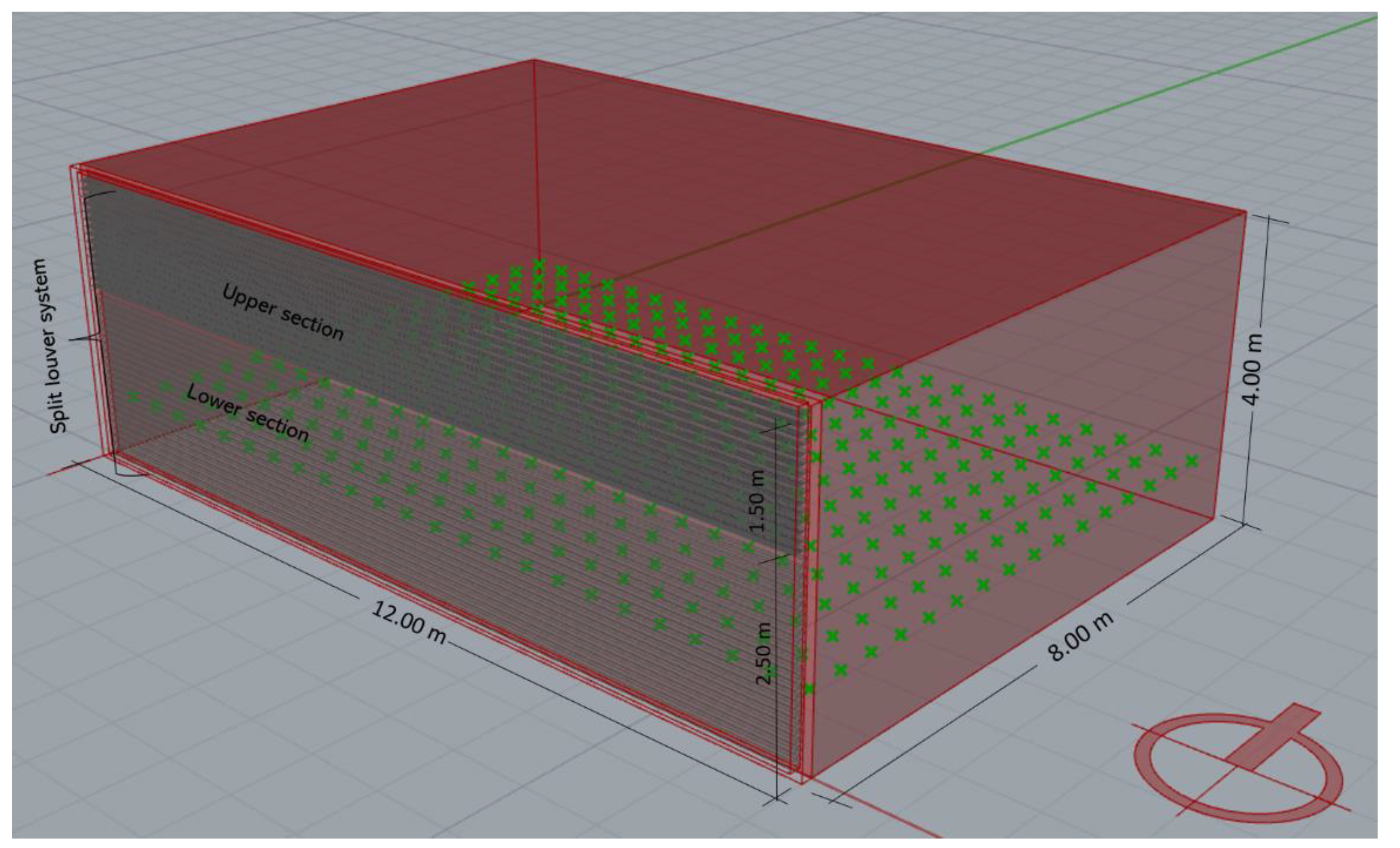
2.1. Model Description
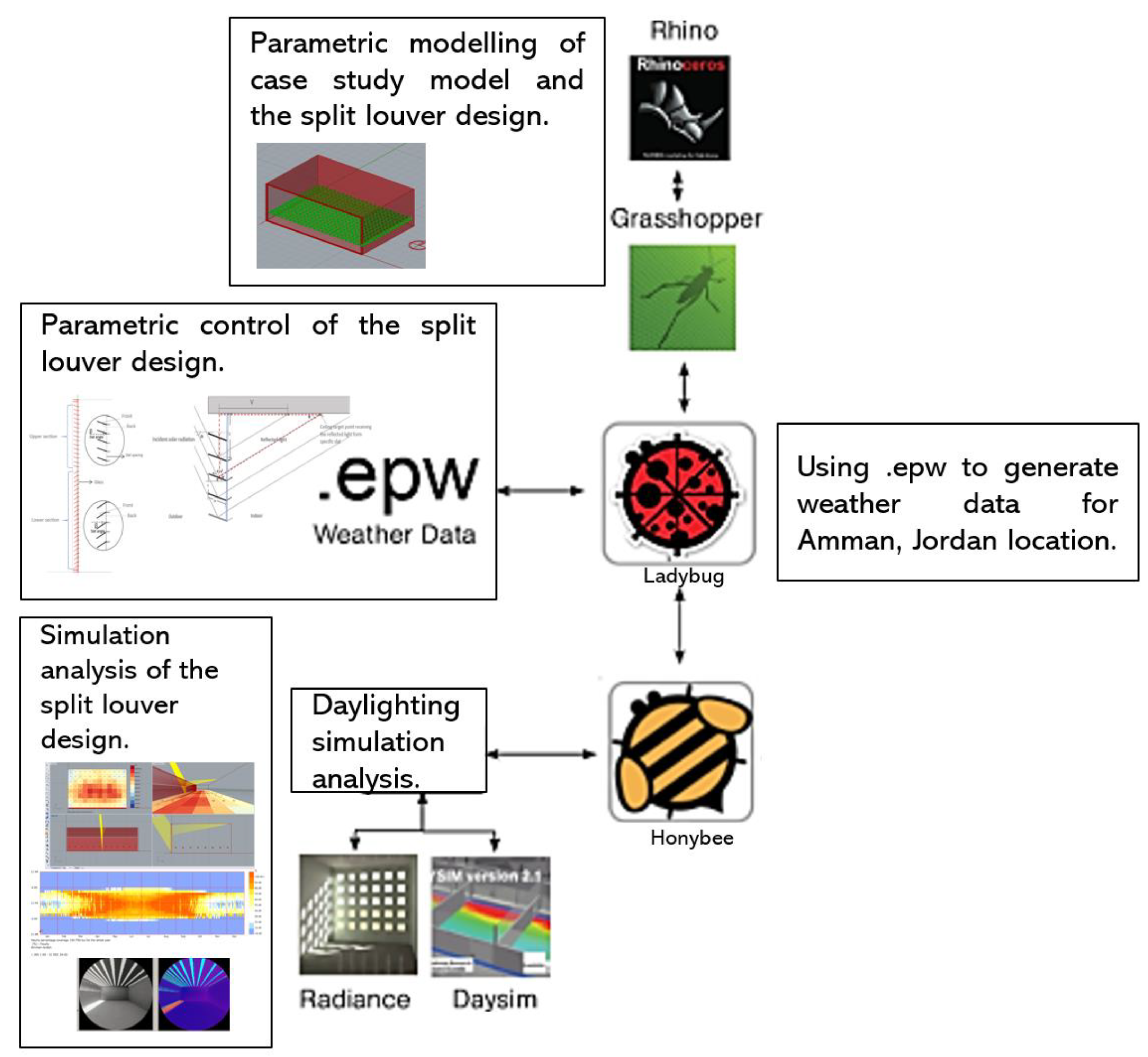
2.2. Grasshopper Modelling
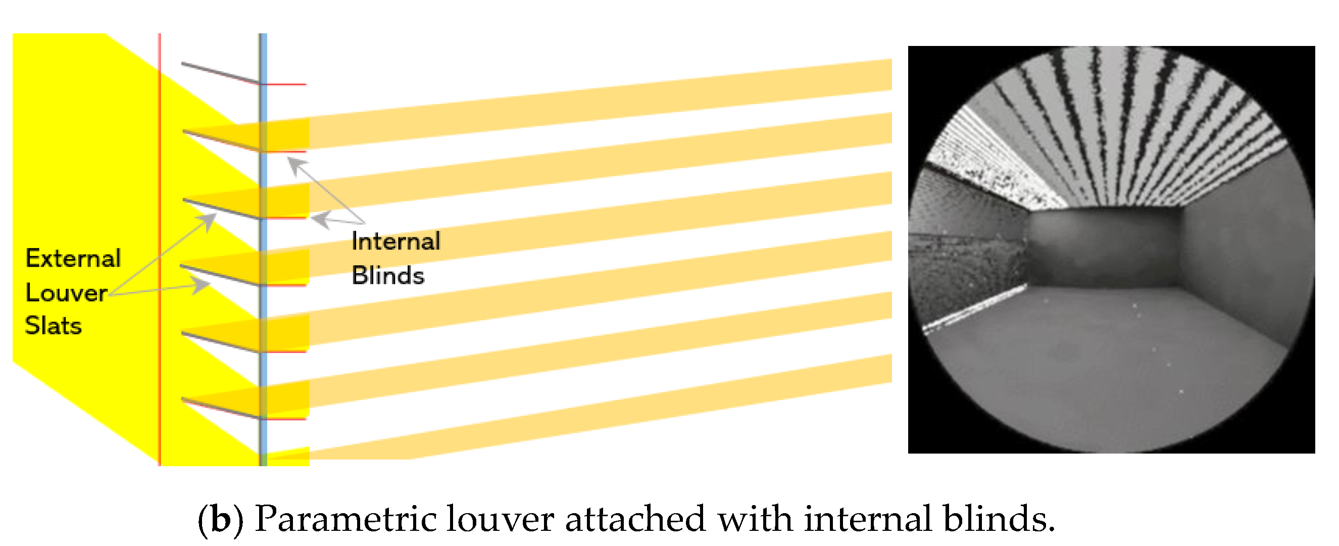
2.3. Research Design Description of the Split Louver System
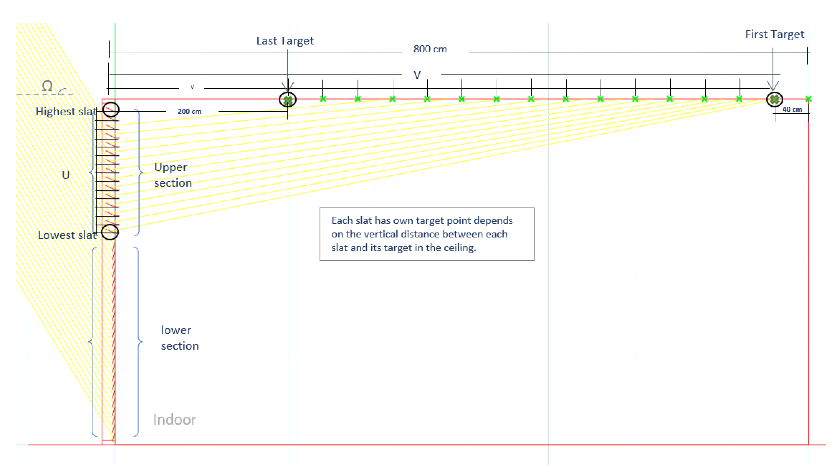
2.3.1. Parametric Design of Split Louver
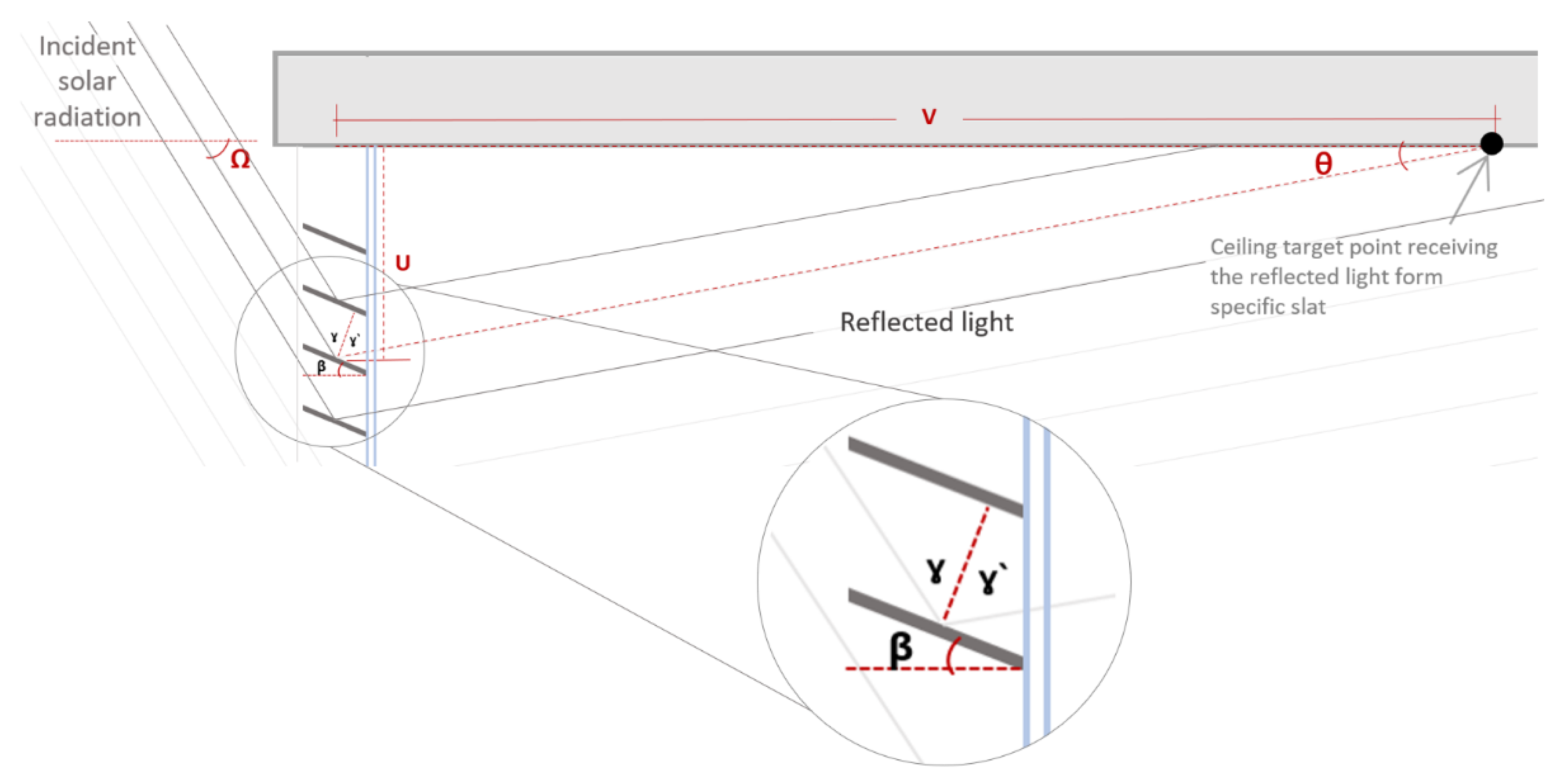
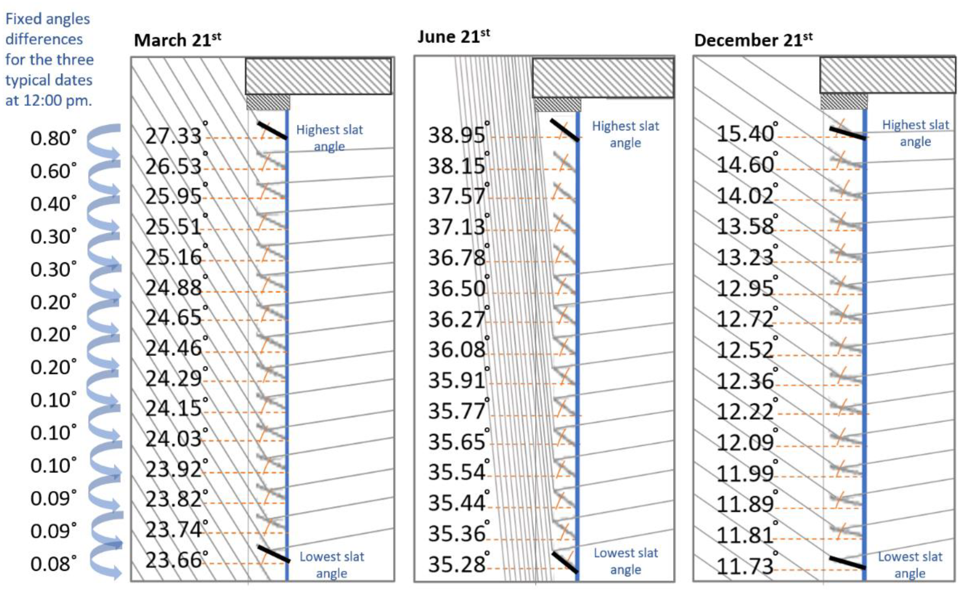
2.3.2. The Simplified Parametric Control of the Slat Angle
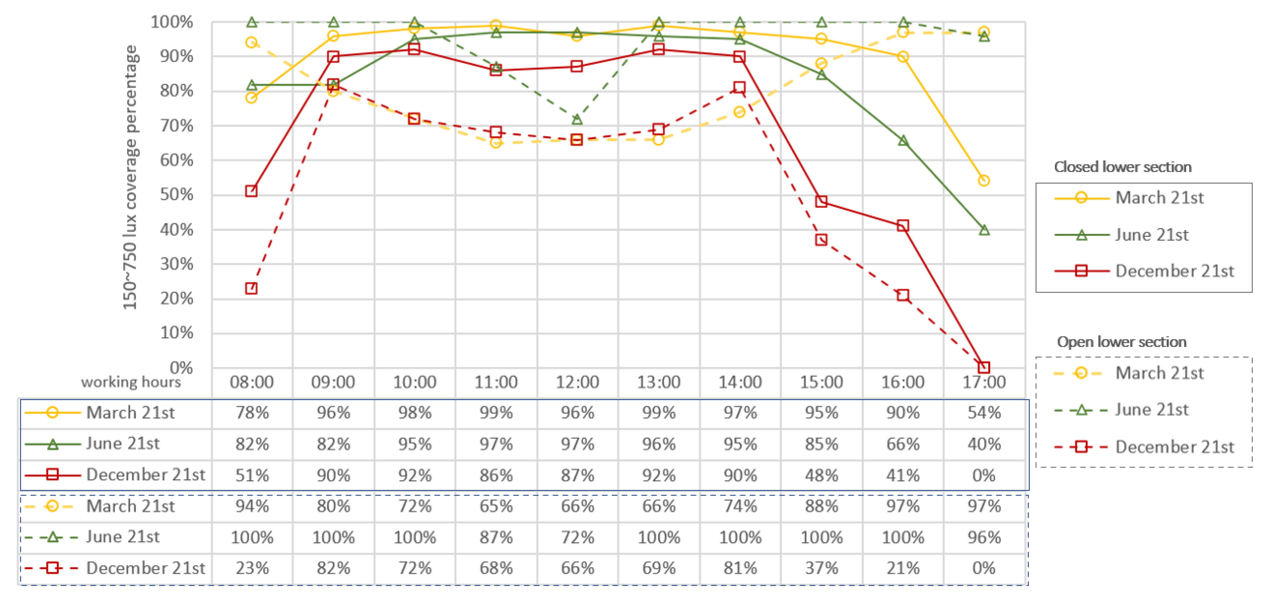
3. Comparative Study and Results
4. Discussions
5. Conclusions
Author Contributions
Funding
Institutional Review Board Statement
Informed Consent Statement
Acknowledgments
Conflicts of Interest
References
- Konis, K.; Selkowitz, S. Effective Daylighting with High-Performance Facades: Emerging Design Practices; Springer: Berlin/Heidelberg, Germany, 2017. [Google Scholar]
- Pastore, L.; Andersen, M. The influence of façade and space design on building occupants’ indoor experience. J. Build. Eng. 2022, 46, 103663. [Google Scholar] [CrossRef]
- Mardaljevic, J. Daylight, indoor illumination and human behavior. In Encyclopedia of Sustainability Science and Technology; Meyers, R.A., Ed.; Springer: New York, NY, USA; pp. 2804–2846.
- Konstantoglou, M.; Tsangrassoulis, A. Dynamic operation of daylighting and shading systems: A literature review. Renew. Sustain. Energy Rev. 2016, 60, 268–283. [Google Scholar] [CrossRef]
- Olbina, S.; Hu, J. Daylighting and thermal performance of automated split-controlled blinds. Build. Environ. 2012, 56, 127–138. [Google Scholar] [CrossRef]
- Olbina, S. Split controlled blinds as a thermal and daylighting environmental control system. In Proceedings of the 3rd CIB International Conference on Smart and Sustainable Built Environments (SASBE2009), Delft, The Netherlands, 2009. [Google Scholar]
- Svetozarevic, B.; Begle, M.; Jayathissa, P.; Caranovic, S.; Shepherd, R.F.; Nagy, Z.; Hischier, I.; Hofer, J.; Schlueter, A. Dynamic photovoltaic building envelopes for adaptive energy and comfort management. Nat. Energy 2019, 4, 671–682. [Google Scholar] [CrossRef]
- Chan, Y.-C.; Tzempelikos, A. Daylighting and energy analysis of multi-sectional facades. Energy Procedia 2015, 78, 189–194. [Google Scholar] [CrossRef] [Green Version]
- Do, C.T.; Chan, Y.-C. Evaluation of the effectiveness of a multi-sectional facade with Venetian blinds and roller shades with automated shading control strategies. Sol. Energy 2020, 212, 241–257. [Google Scholar] [CrossRef]
- Do, C.T.; Chan, Y.-C. Daylighting performance analysis of a facade combining daylight-redirecting window film and automated roller shade. Build. Environ. 2021, 191, 107596. [Google Scholar] [CrossRef]
- Köster, H. Dynamic Daylighting Architecture: Basics, Systems, Projects; Springer Science & Business Media: Berlin/Heidelberg, Germany, 2004. [Google Scholar]
- Kim, J.-H.; Park, Y.-J.; Yeo, M.-S.; Kim, K.-S. An experimental study on the environmental performance of the automated blind in summer. Build. Environ. 2009, 44, 1517–1527. [Google Scholar] [CrossRef] [Green Version]
- Rhee, K.-N.; Jung, G.-J. Evaluation of Indoor Environment and Energy Performance with Slat Adjustment Method of Split Blinds. J. Korean Inst. Archit. Sustain. Environ. Build. Syst. 2020, 401–413. [Google Scholar] [CrossRef]
- Nabil, A.; Mardaljevic, J. Useful daylight illuminance: A new paradigm for assessing daylight in buildings. Lighting Res. Technol. 2005, 37, 41–57. [Google Scholar] [CrossRef]
- Ruck, N.; Aschehoug, O.; Aydinli, S. Daylight in Buildings-A source book on daylighting systems and components. Lawrence Berkeley Natl. Lab 2000, 9910–47493. Available online: http://gaia.lbl.gov/iea21/ (accessed on 15 March 2022).
- Andersen, D.; Foldbjerg, R. Daylight, Energy and Indoor Climate–Basic Book. VELUX Knowledge Centre for Daylight, Energy and Indoor Climate (DEIC) A/S. 2012. Available online: http://www.velux.com/~/media/com/articles/pdf/deic_basic_book_ver%203-0.pdf (accessed on 9 March 2022).
- Littlefair, P.; Aizlewood, M.; Birtles, A. The performance of innovative daylighting systems. Renew. Energy 1994, 5, 920–934. [Google Scholar] [CrossRef]
- Köster, H. Daylighting controls, performance and global impacts. In Sustainable Built Environment; Springer: New York, NY, USA, 2013; Volume 1, pp. 112–162. [Google Scholar] [CrossRef]
- Wienold, J.; Frontini, F.; Herkel, S.; Mende, S. Climate based simulation of different shading device systems for comfort and energy demand. In Proceedings of the 12th Conference of International Building Performance Simulation Association, Sydney, Australia, 14–16 November 2011. [Google Scholar]
- Mandalaki, M.; Tsoutsos, T. Solar Shading Systems: Design, Performance, and Integrated Photovoltaics; Springer: Berlin/Heidelberg, Germany, 2020. [Google Scholar]
- Eltaweel, A.; Yuehong, S. Using integrated parametric control to achieve better daylighting uniformity in an office room: A multi-Step comparison study. Energy Build. 2017, 152, 137–148. [Google Scholar] [CrossRef]
- Köster, H. Daylighting Controls, Performance, and Global Impacts. In Sustainable Built Environments; Loftness, V., Ed.; Springer: New York, NY, USA; pp. 383–429.
- Osterhaus, W.K. Discomfort glare assessment and prevention for daylight applications in office environments. Sol. Energy 2005, 79, 140–158. [Google Scholar] [CrossRef]
- Eltaweel, A.; Su, Y.; Hafez, M.; Eltaweel, W. An automated louver with innovative parametrically-angled reflective slats: Prototyping and validation via using parametric control in Grasshopper along with Arduino board. Energy Build. 2021, 231, 110614. [Google Scholar] [CrossRef]
- Sicurella, F.; Evola, G.; Wurtz, E. A statistical approach for the evaluation of thermal and visual comfort in free-running buildings. Energy Build. 2012, 47, 402–410. [Google Scholar] [CrossRef]
- Lee, J.-H.; Moon, J.W.; Kim, S. Analysis of occupants’ visual perception to refine indoor lighting environment for office tasks. Energies 2014, 7, 4116. [Google Scholar] [CrossRef]
- Freewan, A.A. Impact of external shading devices on thermal and daylighting performance of offices in hot climate regions. Sol. Energy 2014, 102, 14–30. [Google Scholar] [CrossRef]
- Freewan, A.A.; Shao, L.; Riffat, S. Interactions between louvers and ceiling geometry for maximum daylighting performance. Renew. Energy 2009, 34, 223–232. [Google Scholar] [CrossRef]
- Lagios, K.; Niemasz, J.; Reinhart, C.F. Animated building performance simulation (ABPS)–linking Rhinoceros/Grasshopper with Radiance/Daysim. Proc. SimBuild 2010, 4, 321–327. [Google Scholar]
- Eltaweel, A.; Yuehong, S. Parametric design and daylighting: A literature review. Renew. Sustain. Energy Rev. 2017, 73, 1086–1103. [Google Scholar] [CrossRef]
- Roudsari, M.S.; Pak, M.; Smith, A. Ladybug: A parametric environmental plugin for grasshopper to help designers create an environmentally-conscious design. In Proceedings of the 13th International IBPSA Conference, Lyon, France, 26–28 August 2013. [Google Scholar]
- Kharvari, F. An empirical validation of daylighting tools: Assessing radiance parameters and simulation settings in Ladybug and Honeybee against field measurements. Sol. Energy 2020, 207, 1021–1036. [Google Scholar] [CrossRef]
- Eltaweel, A.; Su, Y. Controlling venetian blinds based on parametric design; via implementing Grasshopper’s plugins: A case study of an office building in Cairo. Energy Build. 2017, 139, 31–43. [Google Scholar] [CrossRef] [Green Version]
- Kim, C.-H.; Lee, K.-H.; Kim, K.-S. Evaluation of Illuminance Measurement Data through Integrated Automated Blinds and LED Dimming Controls in a Full-Scale Mock-up. Energies 2020, 13, 3238. [Google Scholar] [CrossRef]
- Chan, Y.-C.; Tzempelikos, A. A hybrid ray-tracing and radiosity method for calculating radiation transport and illuminance distribution in spaces with venetian blinds. Sol. Energy 2012, 86, 3109–3124. [Google Scholar] [CrossRef]
- Chan, Y.-C.; Tzempelikos, A. Efficient venetian blind control strategies considering daylight utilization and glare protection. Sol. Energy 2013, 98, 241–254. [Google Scholar] [CrossRef]
- Lechner, N. Heating, Cooling, Lighting: Sustainable Design Methods for Architects; John Wiley & Sons: Hoboken, NJ, USA, 2014. [Google Scholar]
- Wang, Y.; Chen, Y.; Guo, X.; He, W.; Gao, L. Development of a solar control method of the venetian blinds. Procedia Eng. 2015, 121, 1186–1192. [Google Scholar] [CrossRef] [Green Version]
- Yu, X.; Su, Y. A discussion of inner south projection angle for performance analysis of dielectric compound parabolic concentrator. Sol. Energy 2015, 113, 101–113. [Google Scholar] [CrossRef]
- Eltaweel, A.; Su, Y.; Mandour, M.A.; Elrawy, O.O. A novel automated louver with parametrically-angled reflective slats; design evaluation for better practicality and daylighting uniformity. J. Build. Eng. 2021, 42, 102438. [Google Scholar] [CrossRef]
- Wienold, J. Dynamic daylight glare evaluation. In Proceedings of the Building Simulation—Eleventh International IBPSA Conference, Glasgow, Scotland, 2009; pp. 944–951. [Google Scholar]
- Bodart, M.; Cauwerts, C. Assessing daylight luminance values and daylight glare probability in scale models. Build. Environ. 2017, 113, 210–219. [Google Scholar] [CrossRef]


| Simulation Parameters | Values |
|---|---|
| Model Dimensions | Width: 12 m, Depth: 8 m and Height: 4 m |
| Ceiling Reflectance | Typical white matte paint 80% |
| Wall Reflectance | Typical white matte paint 80% |
| Floor Reflectance | Typical grey flooring 18% |
| Work plane Height | 0.80 m |
| Window wall ratio | South window WWR 95% (Single glazing, 6 mm clear glass with 88% visual transmittance). |
| The split louver system design | Two sections: upper (1.50 m) and lower (2.5 m) |
| Site location | Amman, Jordan (31.9539° N, 35.9106° E) |
| Reference Sky type | Standard CIE Sky (Sunny with direct sunlight) |
| Slat Properties | Values-Upper Section | Values-Lower Section | Split Louver Details |
|---|---|---|---|
| Slat width | 12 cm | 12 cm |  |
| Slat counts | 15 | 23 | |
| Slat spacing | 10 cm | 10 cm | |
| Slat thickness | 1 mm | 1 mm | |
| Slat shape | Flat | Flat | |
| Allowable slat angle range | Parametric angle (the highest slat angle on 21st of June at 12:00 p.m. is 38.95°) | Fully closed (−90°) to fully open with horizontal state (0°) | |
| Reflectance values | Front: 80% diffuse reflection Back: non-reflective | Front: 30% diffuse reflection Back: non-reflective |
| Conventional Single Louver | Split Louver with Parametric Controlled Upper Section and Closed Lower Section | Split Louver with Parametric Controlled Upper Section and Horizontal Lower Section |  | |
| 21st March |  150~750 lux: 0% 300~500 lux: 0% |  150~750 lux: 96% 300~500 lux: 44% |  150~750 lux: 66% 300~500 lux: 14% | |
| 21st June |  150~750 lux: 0% 300~500 lux: 0% |  150~750 lux: 97% 300~500 lux: 52% |  150~750 lux: 72% 300~500 lux: 11% | |
| 21st December |  150~750 lux: 0% 300~500 lux: 0% |  150~750 lux: 87% 300~500 lux: 26% |  150~750 lux: 66% 300~500 lux: 25% |
| Conventional Single Louver | Split Louver with Parametric Controlled Upper Section and Closed Lower Section | Split Louver with Parametric Controlled Upper Section and Horizontal Lower Section |  | |
| 21st March |  150~750 lux: 1% 300~500 lux: 0% |  150~750 lux: 96% 300~500 lux: 55% |  150~750 lux: 80% 300~500 lux: 24% | |
| 21st June |  150~750 lux: 24% 300~500 lux: 0% |  150~750 lux:82% 300~500 lux: 43% |  150~750 lux: 100% 300~500 lux: 56% | |
| 21st December |  150~750 lux: 0% 300~500 lux: 0% |  150~750 lux: 90% 300~500 lux: 34% |  150~750 lux: 82% 300~500 lux: 42% |
| 8:00 a.m. | 10:00 a.m. | 12:00 p.m. |  | |
| 21st March |  150~750 lux: 78% 300~500 lux: 58% |  150~750 lux: 98% 300~500 lux: 51% | 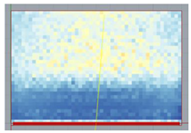 150~750 lux: 96% 300~500 lux: 44% | |
| 21st June | 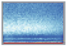 150~750 lux: 82% 300~500 lux: 28% | 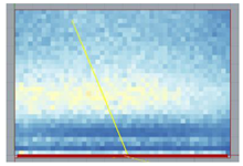 150~750 lux: 95% 300~500 lux: 54% | 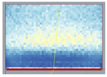 150~750 lux: 97% 300~500 lux: 52% | |
| 21st December | 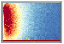 150~750 lux: 51% 300~500 lux: 22% | 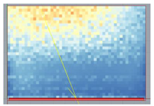 150~750 lux: 92% 300~500 lux: 41% | 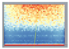 150~750 lux: 94% 300~500 lux: 39% |
| 8:00 a.m. | 10:00 a.m. | 12:00 p.m. |  | |
| 21st March | 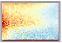 150~750 lux: 94% 3300~500 lux: 40% | 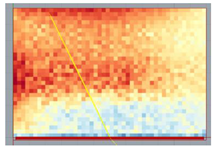 150~750 lux: 72% 300~500 lux: 16% |  150~750 lux: 66% 300~500 lux: 14% | |
| 21st June |  150~750 lux: 100% 300~500 lux: 69% |  150~750 lux: 100% 300~500 lux: 40% | 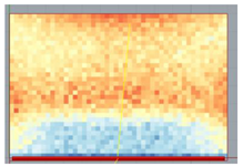 150~750 lux: 72% 300~500 lux: 11% | |
| 21st December | 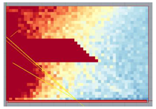 150~750 lux: 23% 300~500 lux: 16% |  150~750 lux: 72% 300~500 lux: 32% |  150~750 lux: 66% 300~500 lux: 25% |
 (a1) Parametric upper section and closed lower section on 21st March. |  (a2) Parametric upper section and horizontally open lower section on 21st March. |
 (b1) Parametric upper section and closed lower section on 21st June. |  (b2) Parametric upper section and horizontally open lower section on 21st June. |
 (c1) Parametric upper section and closed lower section on 21st December. |  (c2) Parametric upper section and horizontally open lower section on 21st December. |
 | |
| Parametric Control (Multiple Variable Slat Angles) | Simplified Parametric Control (One Variable Slat Angle) |  | |
| 21st March |  |  | |
| 21st June |  |  | |
| 21st December |  |  |
| Split Louver with Horizontal Upper Section and Closed Lower Section | Split Louver with Closed Upper Section and Horizontal Lower Section |  | |
| 21st March |  150~750 lux: 89% 300~500 lux: 75% |  150~750 lux: 76% 300~500 lux: 34% | |
| 21st June |  150~750 lux: 96% 300~500 lux: 73% |  150~750 lux: 98% 300~500 lux: 78% | |
| 21st December |  150~750 lux: 95% 300~500 lux: 43% |  150~750 lux: 53% 300~500 lux: 5% |
| Split Louver with Parametric Upper Section and Closed Lower Section | Split Louver with Parametric Upper Section and Horizontal Lower Section | |
|---|---|---|
| 21st March |  |  |
| 21st June | 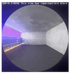 | 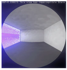 |
| 21st December | 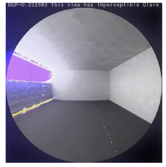 |  |
Publisher’s Note: MDPI stays neutral with regard to jurisdictional claims in published maps and institutional affiliations. |
© 2022 by the authors. Licensee MDPI, Basel, Switzerland. This article is an open access article distributed under the terms and conditions of the Creative Commons Attribution (CC BY) license (https://creativecommons.org/licenses/by/4.0/).
Share and Cite
Alsukkar, M.; Hu, M.; Gadi, M.; Su, Y. A Study on Daylighting Performance of Split Louver with Simplified Parametric Control. Buildings 2022, 12, 594. https://doi.org/10.3390/buildings12050594
Alsukkar M, Hu M, Gadi M, Su Y. A Study on Daylighting Performance of Split Louver with Simplified Parametric Control. Buildings. 2022; 12(5):594. https://doi.org/10.3390/buildings12050594
Chicago/Turabian StyleAlsukkar, Muna, Mingke Hu, Mohamed Gadi, and Yuehong Su. 2022. "A Study on Daylighting Performance of Split Louver with Simplified Parametric Control" Buildings 12, no. 5: 594. https://doi.org/10.3390/buildings12050594