Article

Bearing Capacity of Annular Foundations on Rock Mass with Heterogeneous Disturbance by Finite Element Limit Analysis

Department of Civil Engineering, University of Seoul, Seoul 02504, Korea
*
Author to whom correspondence should be addressed.
Buildings 2022, 12(5), 646; https://doi.org/10.3390/buildings12050646
Submission received: 6 April 2022 / Revised: 30 April 2022 / Accepted: 10 May 2022 / Published: 12 May 2022
(This article belongs to the Section Building Structures)

Abstract

:
Estimating the performance of foundations on rock mass is essential in designing buildings. Stability assessment of weathered rocks under foundation load is a complicated task if there is an internal opening within the foundation. This study applies finite element limit analysis to evaluate the bearing capacity of annular foundations resting on medium to highly weathered rocks following the modified Hoek–Brown rock mass. Special attention is focused on the effect of rock mass disturbance. The level and heterogeneity of rock mass disturbance are considered as constant or linearly varying disturbance factors with depth, which capture the damage level and zones due to construction and blasting. The results obtained from the analysis compare well with the existing solutions. The numerical results are presented in the familiar form of bearing capacity factors as a function of the dimensionless parameters related to foundation perforation and rock mass properties as well as the foundation-rock interface. The failure patterns of annular foundations are also investigated for a few cases with different levels of disturbance and foundation roughness.

1. Introduction

High-rise buildings constructed in urban areas are often placed on weathered rocks with uninform disturbance. Rock mass in its in situ medium has heterogenous and anisotropic properties, and several classification systems of the rock mass have been developed [1]. A good understanding of the stability of rock mass is of great significance to the design of buildings and infrastructure.
Ring footings are commonly used to support axisymmetric structures such as liquid storage tanks, radar stations, chimneys, and silos. The stability of such footings is significantly affected by the mere presence and geometry of perforation. Annular foundations are commonly used to support the silo structure. Many studies have been devoted to estimating the bearing capacity of annular foundations resting on soil mass based on the physical model tests [2,3], the in situ tests [4,5], the limit equilibrium method [6], the method of characteristic [7,8,9], the finite element method [10,11,12], the finite difference method [13,14,15], and the finite element limit analysis [16,17]. In contrast, limited studies have been carried out to determine the bearing capacity of annular foundations over rock mass, though numerous studies have been carried out by researchers [18,19,20]. In their research, results were presented for the perforation ratio as well as the rock mass properties, although the significance of rock mass disturbance is not discussed.
Rock masses consist of rock materials and discontinuities such as joints, fractures, and bedding planes. The strength of such rock media can be quantified by the Hoek–Brown failure criterion, where the rock mass disturbance induced by blasting and/or construction is taken into account by using the disturbance factor D. Several numerical studies on the bearing capacity of rock mass have been reported and most of generally assumed a condition of D = 0. These results can be found in the works of Merifield et al. [21], Saada et al. [22], Clausen [23], Keshavarz and Kumar [24], Chakarborty and Kumar [25], Yang [26], Mansouir et al. [27], and Keawsawasvong et al. [28]. However, a constant D applied to an entire rock mass will not be appropriate, as pointed out by Hoek and Brown [29]. Li et al. [30] reported the stability numbers of heterogenous rock slopes with the variation of D with distance from the face significantly differs from those of the undisturbed and homogenous disturbed rock slopes.
This paper applied finite element limit analysis to estimate the bearing capacity of annular foundations resting on rock mass obeying the modified Hoek–Brown failure criterion and associated flow rule. The obtained solutions are presented in the familiar form of bearing capacity factors and compared with the numerical solutions reported in the literature. The effect of rock mass disturbance on the stability of annular foundation is highlighted.

2. Background

To estimate the non-linear strength envelope of intact rock and jointed rock masses, the original Hoek–Brown (HB) failure criterion was proposed in 1980 and has been subsequently updated. The last version, used here, is expressed as [31]:
σ 1 = σ 3 + σ c i m b σ 3 σ 1 + s a
where σci is the uniaxial compressive strength of the intact rock. σ1 and σ3 are the major and minor principal stresses, respectively, which are considered as positive when tensile in nature. mb, s, and a are the dimensionless material parameters, defined as:
m b = m i   exp G S I 100 28 14 D
s = exp G S I 100 9 3 D
a = 1 2 + 1 6 e GSI / 16 e 20 / 3
where mi is the value of mb for intact rock. The value of mi is related to the minerology and texture of the intact rock, varying from 4 for very fine weak rock (e.g., claystone) to 33 for coarse igneous light-colored rocks (e.g., granite). GSI is the geological strength index which features the quality of the rock mass [32]. The value of GSI ranges from approximately 10 for extremely poor rock masses to 100 for intact rock. D is the disturbance factor which depends on the extent of weathering and blast damage of the rock mass. The value of D varies from 0 for the undisturbed in situ rock masses to 1 for extremely disturbed rock masses. One may recognize that rock mass foundations subjected to less weathering and good blasting attain greater rock mass strength compared to severely disturbed rock mass foundations, indicating that the application of a constant D to an entire rock mass underlying foundation can underpredict the stability of the rock-foundation system. Thus, the heterogeneous disturbance of rock mass should be taken into account in rock foundations.
Using the modified Hoek–Brown failure criterion, the ultimate bearing capacity of surface spread foundations on rock mass qu can be expressed in terms of a dimensionless bearing capacity factor Nσ:
q u =   σ c i N σ
For weightless rock mass, the bearing capacity factor N σ is denoted by N σ 0 .

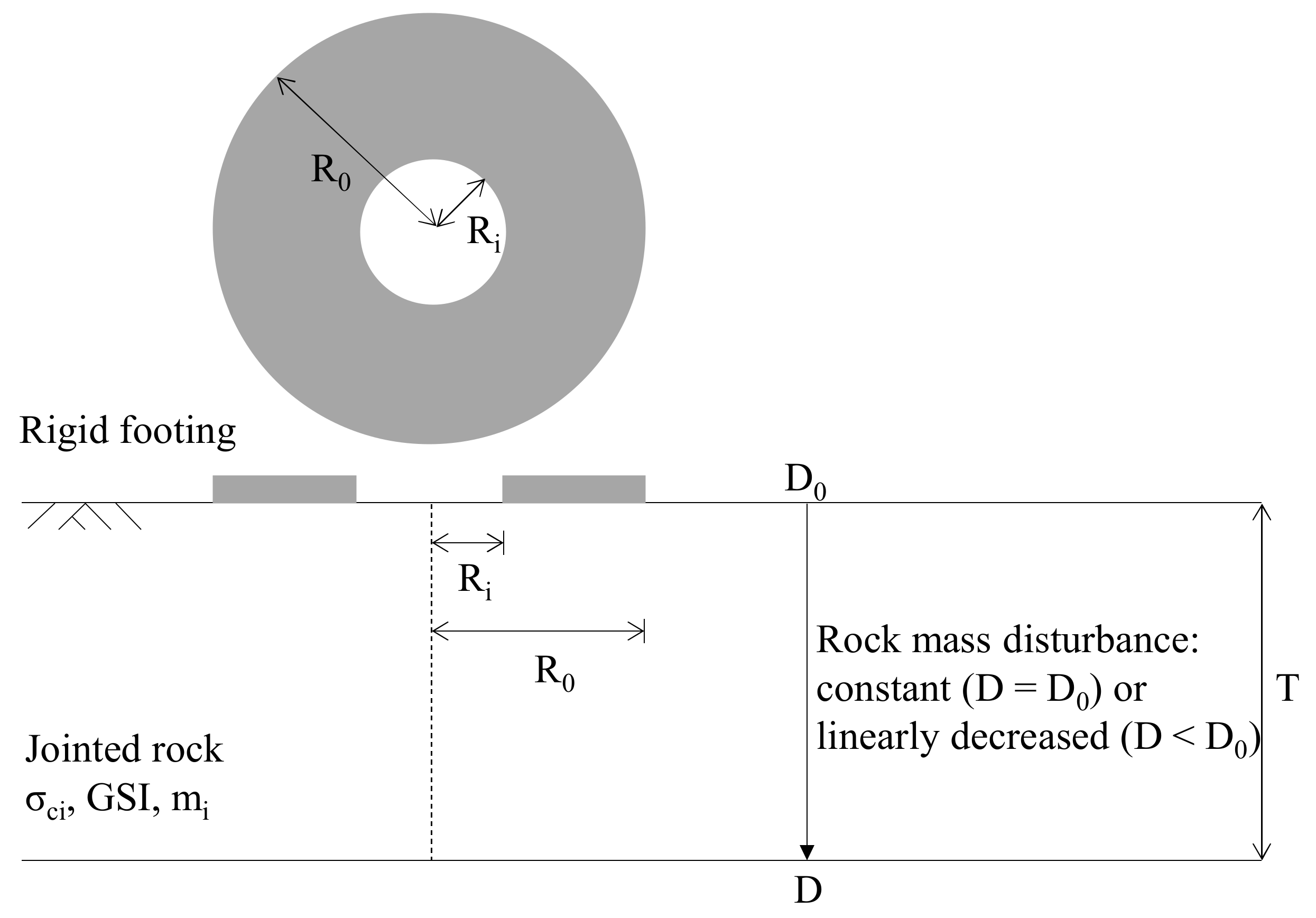
3. Problem Definition

Figure 1 illustrates the geometry and parameters of the rock-foundation system considered. A rigid annular foundation is placed on a rock mass medium with horizontal ground surface. The annular foundation is specified with external and internal radii R0 and Ri, respectively. The base of the foundation is assumed to be perfectly smooth and perfectly rough. The interface between the soil and foundation is prescribed as bonded (i.e., no separation allowed) for rough and frictionless for smooth. A similar assumption is used by Keshavarz and Kumar [8] for circular foundations. The disturbance of rock mass is considered to be homogeneous or heterogeneous. For the homogeneous condition, the disturbance factor D is constant with depth. For the heterogeneous condition, the disturbance factor on the ground surface D0 decreases linearly with depth and becomes zero at the damage depth from the ground surface T.
For convenience in analysis, dimensionless parameters for geometry and materials are introduced. The perforation of annular foundations is presented as the external-to-internal radius ratios Ri/R0. The value of Ri/R0 ranges from 0 to 0.75, which covers most problems of practical interest [11,12]. The unit weight of rock γ was quantified as σci/γR0, varying from 250 to ∞. The infinite value of σci/γR0 indicates the weightless rock mass. The values of GSI and mi are within the range of 10–100 and 5–35, respectively. The damage depth of heterogeneous disturbance is quantified as T/R0, which ranges from 1 to 5.

4. Finite Element Limit Analysis

All of the calculations in this study were carried out using the commercial software OptumG2 [33], which enables calculations of the collapse loads for geotechnical stability problems using the finite element limit analysis (FELA). This numerical technique combines the discretization of finite elements for handling intricate soil properties, loadings, and boundary conditions, with the plastic bound theorems of limit analysis to obtain the exact limit load by upper bound (UB) and lower bound (LB) solutions. The LB solution aims for the lower bound of the ultimate load in the static admissible stress field, while the UB solution considers that there exists an upper bound of the true bearing capacity based on the kinematically allowable velocity field [34]. All numerical results from the present study are described by using an average (AVG) solution:
AVG = UB + LB / 2
Figure 2 shows the problem domain and boundary conditions. The foundation is adopted as a weightless and perfectly rigid element. To achieve a perfectly smooth and perfectly rough interface between the rock mass and foundation, the interface factors are set as 0 and 1. Due to an axisymmetric distribution of the stress about a vertical line passing through the center of the foundation, only half of the problem domain was considered. To avoid the boundary effect, the horizontal boundary was placed 20R0 away from the edge of the foundation, and the vertical boundary was placed at a depth of 15R0 from the surface. Both horizontal and vertical boundaries were modeled to prevent radial displacement, and the bottom boundary was modeled as fully fixed to prevent radial and vertical displacement. Adaptive meshing in FELA is used to decrease the gap between the upper and lower bound estimates of the failure load to a minimum. This technique is normally based on an error determination of some control parameters.

5. Results and Comparison

Figure 3 provides the obtained Nσ0 values of a circular foundation (Ri/R0 = 0) on undisturbed weightless rock mass (D = 0 and σci/γR0 = ∞), together with other numerical analyses for equivalent conditions. This result indicates the variation of Nσ0 values with mi for the case of GSI = 10, 50 and 100. As shown in the Figure 3, the results of the numerical analysis are very close to those obtained with the finite element method of Clausen [23] and method of characteristics of Keshavarz and Kumar [24]. For example, the Nσ0 values of 1.61 for mi =10 and GSI = 50 is obtained, which are <4% in error compared with those from Clausen [23] and Keshavarz and Kumar [24], i.e., 1.65 and 1.67, respectively. The expression from the lower bound finite element method of Chakarborty and Kumar [24] gives values that are consistent with the present numerical analysis results, except for Nσ0 values of GSI = 10. Furthermore, even under conditions other than given GSI values, Nσ0 values are consistent with comparable numerical analysis results.
The variation of the bearing capacity factors Nσ for different combinations of Ri/R0 and GSI is shown in Figure 4 for the case of mi = 15, D0 = 0 and σci/γR0 = 1000, 10,000 and infinite (=weightless soil). For each GSI at a given value of σci/γR0, there is little effect on the Nσ values due to the increase in Ri/R0. This indicates that the unit weight of the rock mass has little influence on the value of Nσ. Figure 4 also shows an increase in the value of Nσ as the GSI increases, and compares the Nσ values obtained from the present analysis to the results of Xiao et al. [18] when GSI = 10 and 100 of weightless soil. It can be observed that the present solutions compare reasonably well with the results of Xiao et al. [18].
The variation of the bearing capacity factors Nσ for different combinations of Ri/R0 and σci/γR0 is shown in Figure 5 for the case of GSI = 50, D0 = 0, and mi = 5, 15, 25, and 35. The result shows that as Ri/R0 increases from 0 to 0.25 the value of Nσ increases, reaching the peak of bearing capacity. However, when Ri/R0 becomes a value higher than 0.25 the value of Nσ decreases as Ri/R0 increases. Figure 5a,b show that for low intact rock parameters (mi ≤ 15). When Ri/R0 ≤ 0.25, the variation in the value of Nσ increases as σci/γR0 increases, which is greater when mi is 15 rather than 5. It is also noted that for all annular foundations, except where Ri/R0 is 0.25, there is less Nσ than the circular foundation (Ri/R0 = 0). On the other hand, Figure 5c,d demonstrate this for high intact rock parameters (mi ≥ 25). Different from Figure 5a,b described earlier, σci/γR0 exhibits almost the same tendency due to it not affecting the Nσ values. In addition, when mi is greater than 25, the range of Ri/R0 where the value of Nσ is greater than the circular foundation of 0.25 to 0.33.
The variation of the bearing capacity factors Nσ of rock mass with homogeneous disturbance factor D for different combinations of Ri/R0 and mi is shown in Figure 6 for the case of σci/γR0 = 1000, GSI = 50, D = 0, and mi = 5, 15, 25, and 35. As expected, the value of Nσ decreases as disturbance factor D increases. Furthermore, the variation in Nσ values due to the increase in Ri/R0 decreases as D increases. This implies that the larger D, the less influence on the external-to-internal radius ratios Ri/R0. It is also noticed that, for a given each value of mi, the tendency for Nσ values to peak at Ri/R0 = 0.25 becomes more pronounced as mi increases. In addition, it can be seen that when mi is less than 15, the Nσ value remains almost constant because the increase in Ri/R0 does not affect the Nσ value.
The variation of the bearing capacity factor Nσ of rock mass with heterogeneous disturbed regions T/R0 for different combinations of Ri/R0 and D0 is shown in Figure 7 for the case of σci/γR0 = 1000, GSI = 50, mi = 15, D = 0, and D0 = 0, 0.5, and 1.0. It is observed that as the heterogeneous disturbed region T/R0 increases, the Nσ values of D0 = 0.5 and D0 = 1.0, excluding undisturbed (D0 = 0), decrease. In addition, a larger T/R0 diminishes the rate of decrease in the value of Nσ as increases in Ri/R0. Furthermore, as the values of D0 increase, the peak of bearing capacity becomes the circular foundation (Ri/R0 = 0) rather than the value of Ri/R0 = 0.25 in the annular foundation. Additionally, when T/R0 is greater than 4, the value of heterogenous rock mass Nσ is approximately equal to that Nσ value of the rock mass of homogenous. This is described in more detail in the following Figure 8.
The variation of the bearing capacity factor Nσ of rock mass with linear decrease disturbance factor D0 for different combinations of T/R0 and Ri/R0 is shown in Figure 8 for the case of σci/γR0 = 1000, GSI = 50, mi = 15, and D = 0. As expected, the value of Nσ decreases as D0 increases. However, it can be seen that the Nσ value of each Ri/R0, due to the increase in T/R0, has the same trend because the rate of diminishing is almost identical. It is also noticed that the Nσ values decrease the most in the circular foundation (Ri/R0 = 0), and the Nσ values rate of decrease diminishes with the increase in Ri/R0. Furthermore, it can be seen that for the given values of D0, the value of Nσ decreases to an increase in T/R0 up to T/R0 ≈ 4, and, thereafter, the value of Nσ becomes almost constant.
The variation of bearing capacity factor Nσ of unit wight, GSI, mi, and D of rock mass with smooth and rough bases for different combinations of Ri/R0 is shown in Figure 9. The results indicate that for an annular foundation with a smooth base, the peak of bearing capacity occurs at the circular foundation (Ri/R0 = 0). It can also be seen that for all parameters, the Nσ values are smaller than the annular foundation of the rough base, and the Nσ value decreases continuously as Ri/R0 increases. Figure 9a shows that the variation of Nσ values at a smooth and rough bases for the unit weights of rock mass. The largest difference in Nσ values due to roughness is a Ri/R0 value of 0.25, and the difference in Nσ values is expected to increase as is the peak of bearing capacity significantly in the case of rough bases. Figure 9b shows that the variation of Nσ values at smooth and rough bases for GSI of rock mass. It can be seen that the difference in Nσ values due to roughness are not significant for given values of GSI. Figure 9c shows that the variation of Nσ values at smooth and rough bases for the mi of rock mass. The difference in Nσ values due to roughness is the largest difference when the Ri/R0 value is 0.25, such as in Figure 9a. In addition, the decrease in mi indicates a difference in Nσ values due to roughness decreasing. Figure 9d shows that the variation of Nσ values at a smooth and rough base for D of rock mass. It can be seen that the difference in Nσ values due to roughness decrease as D decreases. This shows that the mi in Figure 9c has the same tendency to decrease.
Since the failure mechanisms obtained from UB and LB methods are slightly different, only failure mechanisms obtained from the UB method are used to portray the effects of HB parameters as well as the condition of loading. Figure 10 shows the cases of the rough base annular foundations on the rock masses for different homogeneous disturbed with Ri/R0 = 0.5, σci/γR0 = 1000, GSI = 50, and mi = 15. It is found that the size of the failure mechanism depends on the disturbance factor D, where the failure mechanism for the cases of D = 1 values are smaller than that of D = 0 values. In other words, the smaller the disturbance factor D, the greater the Nσ values, but the wider the failure mechanism. It is also noticed that the largest failure mechanism corresponds to 6.2R0 at the edge of the annular foundation and the smallest failure mechanism corresponds to 4.3R0 at the edge of the annular foundation.
Figure 11 shows the cases of the smooth and rough bases annular foundations on the rock masses with Ri/R0 = 0.5, σci/γR0 = 1000, GSI = 50, mi = 15, and D = 0. In the case of Figure 11a, which is a rough base annular foundation, the failure mechanism is formed by intersecting under the annular foundation. On the other hand, in the case of Figure 11b, which is a smooth base annular foundation, the failure mechanism of the external radius is not included in the internal radius region because the failure mechanism does not intersect. It is also noticed that the rough base annular foundation failure mechanism has a larger region compared to the smooth base annular foundation failure mechanism.

6. Conclusions

The following conclusions can be drawn from the present study:
  • The bearing capacity factors Nσ obtained from the finite element limit analysis are in good agreement with those from analytical methods reported in literature for weightless undisturbed rock mass.
  • As Ri/R0 increases, the value of Nσ increases first and then decreases: the peak value of Nσ is achieved at Ri/R0 = 0.25, indicating the optimal opening ratio such that the bearing capacity of annular foundations against the vertical loading is maximum. The Nσ value increases continuously with increasing GSI and mi. However, an increase in σci/γR0 leads to a decrease in Nσ and the effect of σci/γR0 on Nσ is more predominant for smaller value of Ri/R0.
  • The rock mass disturbance has significant effect on the value of Nσ. For constant D, the Nσ value decreases with increasing D, implying that for poor quality rock masses, no consideration of disturbance (D = 0) will overestimate the bearing capacity of rock foundations. For heterogeneous D (which decreases linearly with depth), the Nσ value decreases with an increase in T/R0. This means that the larger thickness of rock disturbance zone gives rise to the lower stability of annular foundations.
  • The values of Nσ for a rough foundation for all values of GSI, mi, σci/γR0 and D are always larger than those for a smooth foundation. In general, the maximum difference between the Nσ values occurs at Ri/R0 = 0.25.
  • In the failure mechanism of annular foundations, the extent of failure surface for an undisturbed rock mass is greater than that for a disturbed rock mass. In terms of internal plastic zone, a smooth foundation provides a local soil failure near ground surface, but its region is small compared with the corresponding rough foundation.

Author Contributions

Writing and original draft preparation, B.S.K. and J.K.L. Assistance with data analysis, O.-i.K. and Y.H.C. All authors have read and agreed to the published version of the manuscript.

Funding

The authors acknowledge support in this research for the National Research Foundation of Korea (NRF) (Grant No. NRF-2020R1C1C1005374).

Institutional Review Board Statement

The study did not require any ethical approval.

Informed Consent Statement

Not applicable.

Data Availability Statement

No applicable.

Conflicts of Interest

The authors declare no conflict of interest.

References

  1. Singh, B.; Goel, R.K. Engineering Rock Mass Classification: Tunneling, Foundations, and Landslides; Elsevier: Oxford, MS, USA, 2011. [Google Scholar]
  2. Boushenrian, J.H.; Hataf, N. Experimental and numerical investigation of the bearing capacity of model circular and ring foundations on reinforced sand. Geotext. Geomembr. 2003, 21, 241–256. [Google Scholar] [CrossRef]
  3. Sawwaf, M.E.; Nazir., A. Behavior of eccentrically loaded small-scale ring foundations resting on reinforced layered soil. J. Geotech. Geoenviron. Eng. 2012, 138, 376–384. [Google Scholar] [CrossRef]
  4. Ismael, N.F. Loading tests on circular and ring plates in very dense cemented sands. J. Geotech. Eng. 1996, 122, 281–287. [Google Scholar] [CrossRef]
  5. Ostroumov, B.V.; Khanin, R.E. Design and construction of a ring foundation for a radio-television tower. Soil Mech. Found. Eng. 2007, 44, 137–142. [Google Scholar] [CrossRef]
  6. Becker, D.E.; Burwash, W.J.; Montgomery, R.A.; Liu, Y. Foundation design aspects of the Confederation Bridge. Can. Geotech. J. 1998, 35, 750–768. [Google Scholar] [CrossRef]
  7. Kumar, J.; Ghosh, P. Bearing capacity factor Nγ for ring foundations using the method of characteristics. Can. Geotech. J. 2005, 42, 1474–1484. [Google Scholar] [CrossRef]
  8. Keshavarz, A.; Kumar, J. Bearing capacity computation for a ring foundation using the stress characteristics method. Comput. Geotech. 2017, 89, 33–42. [Google Scholar] [CrossRef]
  9. Gholami, H.; Hosseininia, E.S. Bearing capacity factors of ring foundations by using the method of characteristics. Geotech. Geol. Eng. 2017, 35, 2137–2146. [Google Scholar] [CrossRef]
  10. Laman, M.; Yildiz, A. Numerical studies of ring foundations on geogrid-reinforced sand. Geosynth. Int. 2007, 14, 52–64. [Google Scholar] [CrossRef]
  11. Lee, J.K.; Jeong, S.; Lee, S. Undrained bearing capacity factors for ring foundations in heterogeneous soil. Comput. Geotech. 2016, 75, 103–111. [Google Scholar] [CrossRef]
  12. Lee, J.K.; Joeng, S.; Shang, J.Q. Undrained bearing capacity of ring foundations on two-layered clays. Ocean Eng. 2016, 119, 47–57. [Google Scholar] [CrossRef]
  13. Zhoa, L.; Wang, J.H. Vertical bearing capacity for ring foundations. Comput. Geotech. 2008, 35, 292–304. [Google Scholar] [CrossRef]
  14. Benmebarek, S.; Remadna, M.S.; Benmebarek, N.; Belounar, L. Numerical evaluation of the bearing capacity factor Nγ of ring foundations. Comput. Geotech. 2012, 44, 132–138. [Google Scholar] [CrossRef]
  15. Sargazi, O.; Hosseininia, E.S. Bearing capacity of ring foundations on cohesionless soil under eccentric load. Comput. Geotech. 2017, 92, 169–178. [Google Scholar] [CrossRef]
  16. Kumar, J.; Chakraborty, M. Bearing capacity factors for ring foundations. J. Geotech. Geoenviron. Eng. 2015, 141, 06015007. [Google Scholar] [CrossRef]
  17. Tang, C.; Phoon, K. Prediction of bearing capacity of ring foundation on dense sand with regard to stress level effect. Int. J. Geomech. 2018, 18, 04018154. [Google Scholar] [CrossRef]
  18. Xiao, Y.; Zhao, M.; Zhao, H.; Zhang, R. Numerical study on bearing capacity of ring foundations for storage tanks on a rock mass. Arab. J. Geosci. 2020, 13, 1249. [Google Scholar] [CrossRef]
  19. Yodsomjai, W.; Keawsawasvong, S.; Lai, V.Q. Limit analysis solutions for bearing capacity of ring foundations on rocks using Hoek-Brown Failure Criterion. Int. J. Geosynth. Ground. Eng. 2021, 7, 29. [Google Scholar] [CrossRef]
  20. Keshavarz, A.; Kumar, J. Bearing capacity of ring foundations over rock mass. J. Geotech. Geoenviron. Eng. 2021, 149, 04021027. [Google Scholar] [CrossRef]
  21. Merifield, R.S.; Lyamin, A.V.; Sloan, S.W. Limit analysis solutions for the bearing capacity of rock mass using the generalized Hoek-Brown criterion. Int. J. Rock. Mech. Min. Sci. 2006, 43, 920–937. [Google Scholar] [CrossRef]
  22. Saada, Z.; Maghous, S.; Garnier, D. Bearing capacity of shallow foundations on rocks obeying a modified Hoek-Brown failure criterion. Comput. Geotech. 2008, 35, 144–154. [Google Scholar] [CrossRef]
  23. Clausen, J. Bearing capacity of circular foundations on a Hoek-Brown material. Int. J. Rock. Mech. Min. Sci. 2013, 57, 4–41. [Google Scholar] [CrossRef]
  24. Keshavarz, A.; Kumar, J. Bearing capacity of foundations on rock mass using the method of characteristics. Int. J. Numer. Anal. Met. Geomech. 2014, 42, 542–557. [Google Scholar] [CrossRef] [Green Version]
  25. Chakraborty, M.; Kumar, J. Bearing capacity of circular footings over rock mass by using axisymmetric quasi lower bound finite element limit analysis. Comput. Geotech. 2015, 70, 138–149. [Google Scholar] [CrossRef]
  26. Yang, X. Lower-bound analytical solution for bearing capacity factor using modified Hoek-Brown failure criterion. Can. Geotech. J. 2018, 55, 577–583. [Google Scholar] [CrossRef]
  27. Mansouri, M.; Imani, M.; Fahimifar, A. Ultimate bearing capacity of rock masses under square and rectangular foundations. Comput. Geotech. 2019, 111, 1–9. [Google Scholar] [CrossRef]
  28. Keawsavasvong, S.; Thongchom, C.; Likitlersuang, S. Bearing capacity of strip foundation on Hoek-Brown rock mass subjected to eccentric and inclined loading. Transp. Infrastruct. Geotechnol. 2020, 8, 189–202. [Google Scholar] [CrossRef]
  29. Hoek, E.; Brown, E.T. The Hoek-Brown failure criterion and GSI—2018 Edition. J. Rock Mech. Geotech. Eng. 2019, 11, 445–463. [Google Scholar] [CrossRef]
  30. Li, A.J.; Merifield, R.S.; Lyamin, A.V. Effect of rock mass disturbance on the stability of rock slopes using the Hoek-Brown failure criterion. Comput. Geotech. 2011, 38, 546–558. [Google Scholar] [CrossRef]
  31. Hoek, E.; Carranza-Torres, C.; Corkum, B. Hoek-Brown failure criterion-2002 edition. In Proceedings of the North American Rock Mechanics Symposium, Toronto, ON, Canada, 7–10 July 2002. [Google Scholar]
  32. Marinos, V.; Marinos, P.; Hoek, E. The geological strength index: Applications and limitations. Bull. Eng. Geol. Environ. 2005, 64, 55–65. [Google Scholar] [CrossRef]
  33. Krabbenhoft, K.; Lyamin, A.; Krabbenhoft, J. Optum Computational Engineering (OptumG2). 2015. Available online: www.optumce.com (accessed on 9 May 2022).
  34. Sloan, S.W. Geotechnical stability analysis. Geotechnique 2013, 63, 531–572. [Google Scholar] [CrossRef] [Green Version]
Figure 1. Problem definition.
Buildings 12 00646 g001
Figure 2. Problem domain and boundary conditions.
Buildings 12 00646 g002
Figure 3. Comparison of Nσ0 values for circular rough footings on an undisturbed weightless rock (D = 0 and σci/γR0 = ∞).
Buildings 12 00646 g003
Figure 4. Variation of Nσ values with Ri/R0 and GSI for homogeneous rock mass with mi = 15 and D = 0: (a) σci/γR0 = 1000; (b) σci/γR0 = 1000; and (c) σci/γR0 = ∞.
Buildings 12 00646 g004
Figure 5. Variation of Nσ values with Ri/R0 and σci/γR0 for homogeneous rock mass with GSI = 50 and D = 0: (a) mi = 5; (b) mi = 15; (c) mi = 25; and (d) mi = 35.
Buildings 12 00646 g005
Figure 6. Variation of Nσ values with Ri/R0 and mi for homogeneous rock mass with σci/γR0 = 1000 and GSI = 50: (a) D = 0; (b) D = 0.5; and (c) D = 1.
Buildings 12 00646 g006
Figure 7. Variation of Nσ values with Ri/R0 and D0 for heterogeneous rock mass with σci/γR0 = 1000, GSI = 50, and mi = 15: (a) T/R0 = 1; (b) T/R0 = 2; (c) T/R0 = 3; (d) T/R0 = 4; and (e) T/R0 = 5.
Buildings 12 00646 g007
Figure 8. Variation of Nσ values with T/R0 and Ri/R0 for heterogeneous rock mass with σci/γR0 = 1000, GSI = 50, and mi = 15: (a) D0 = 0.5; and (b) D0 = 1.0.
Buildings 12 00646 g008
Figure 9. Nσ values for smooth and rough annular footings on homogeneous rock mass. (a) GSI = 50, mi = 15, D = 0. (b) σci/𝛾R0 = 1000, mi = 15, D = 0. (c) σci/𝛾R0 = 1000, GSI = 50, D = 0. (d) σci/𝛾R0 = 1000, GSI = 50, mi = 15.
Buildings 12 00646 g009
Figure 10. Failure patterns of homogeneous rock masses under annular rough footing with Ri/R0 = 0.5, σci/𝛾R0 = 1000, GSI = 50, and mi = 15: (a) undisturbed (D = 0) and (b) disturbed (D = 1) rocks.
Buildings 12 00646 g010
Figure 11. Failure patterns of (a) rough and (b) smooth annular footings with Ri/R0 = 0.5, σci/𝛾R0 = 1000, GSI = 50, mi = 15, and D = 0.
Buildings 12 00646 g011
Publisher’s Note: MDPI stays neutral with regard to jurisdictional claims in published maps and institutional affiliations.

