
Effects of Floor System on Progressive Collapse Behavior of RC Frame Sub-Assemblages


Abstract
:1. Introduction
2. Framework of the Study
- The minimum slab thickness was calculated according to the ACI 318-14 [50] design code considering the relative rigidity between the slab and beams.
- The slab thickness was used to accurately calculate the dead load of the floor system.
- spSlab/spBeam software [51] was used to design the floor system in accordance with ACI 318-14 design code requirements.
- The numerical model using SeismoStruct software [52] was employed to perform nonlinear push-down analyses and examine the progressive collapse-resistance of the different designs of the structure under a middle-column removal scenario. The validity of the numerical model was demonstrated in previously published work by the authors [53].
- The analysis and interpretation of the numerical results were presented.
- The conclusions and future recommendations were drawn and proposed.
3. RC Frame Sub-Assemblages with Varying Design Options
3.1. Sub-Assemblage Configurations and Material Properties
3.2. Sub-Assemblage Varying Design Options
4. Numerical Modeling for Progressive Collapse Analysis of Designed Sub-Assemblages
5. Numerical Results and Discussions
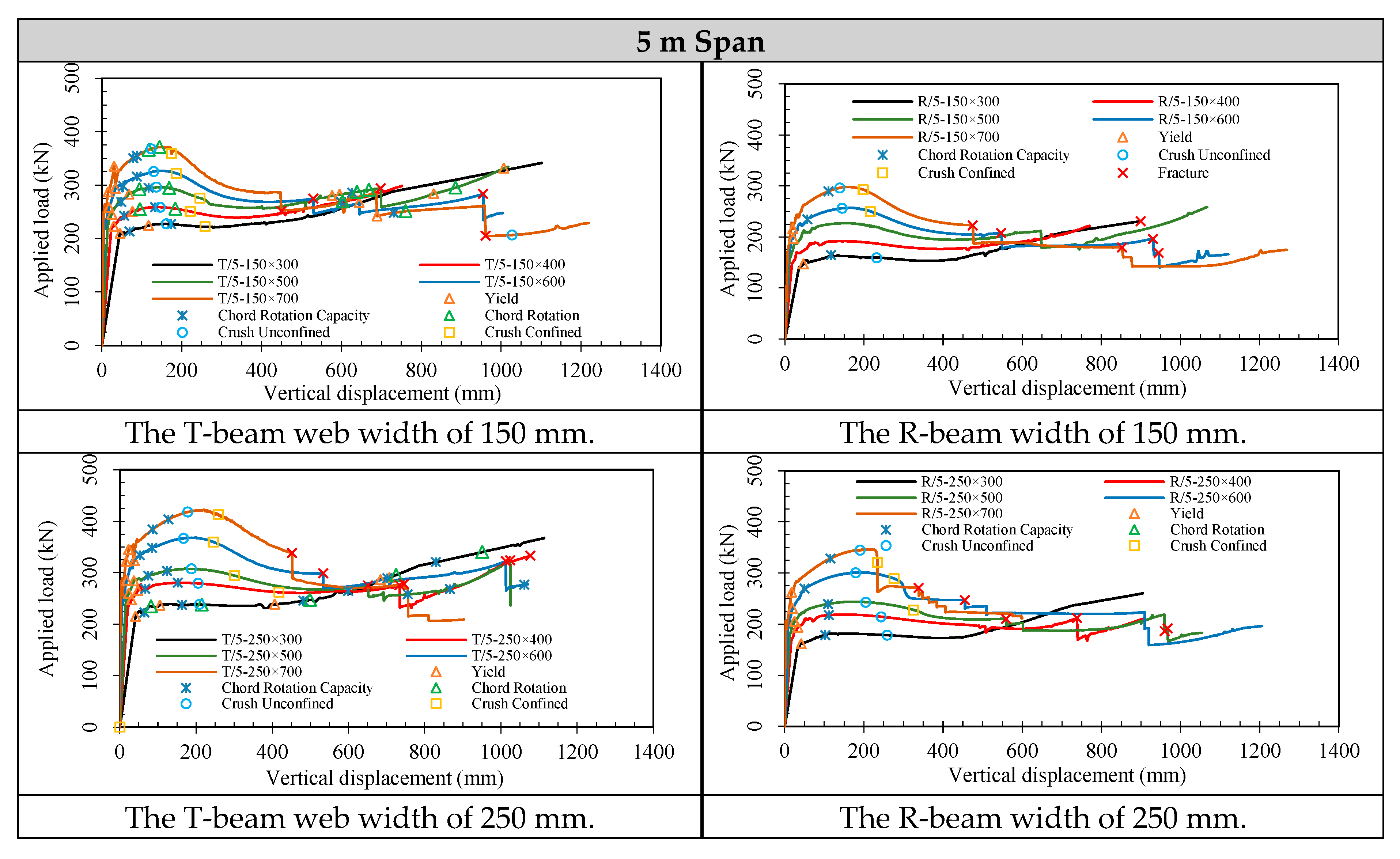
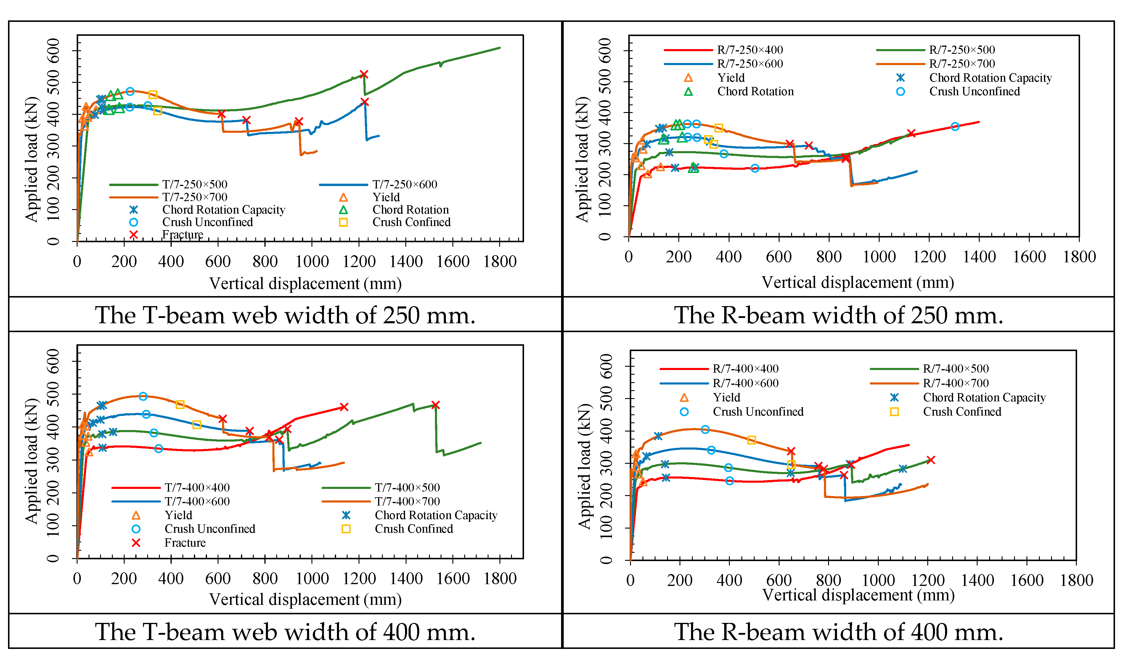
5.1. Influence of Varying Design Options on the Load-Displacement Curves
5.2. Influence of Varying Design Options on the Capacity and Dissipated Energy
5.2.1. Influence of Varying Design Options on the Capacity
5.2.2. Influence of Varying Design Options on the Dissipated Energy
5.2.3. Impact of Slab on Energy Dissipation
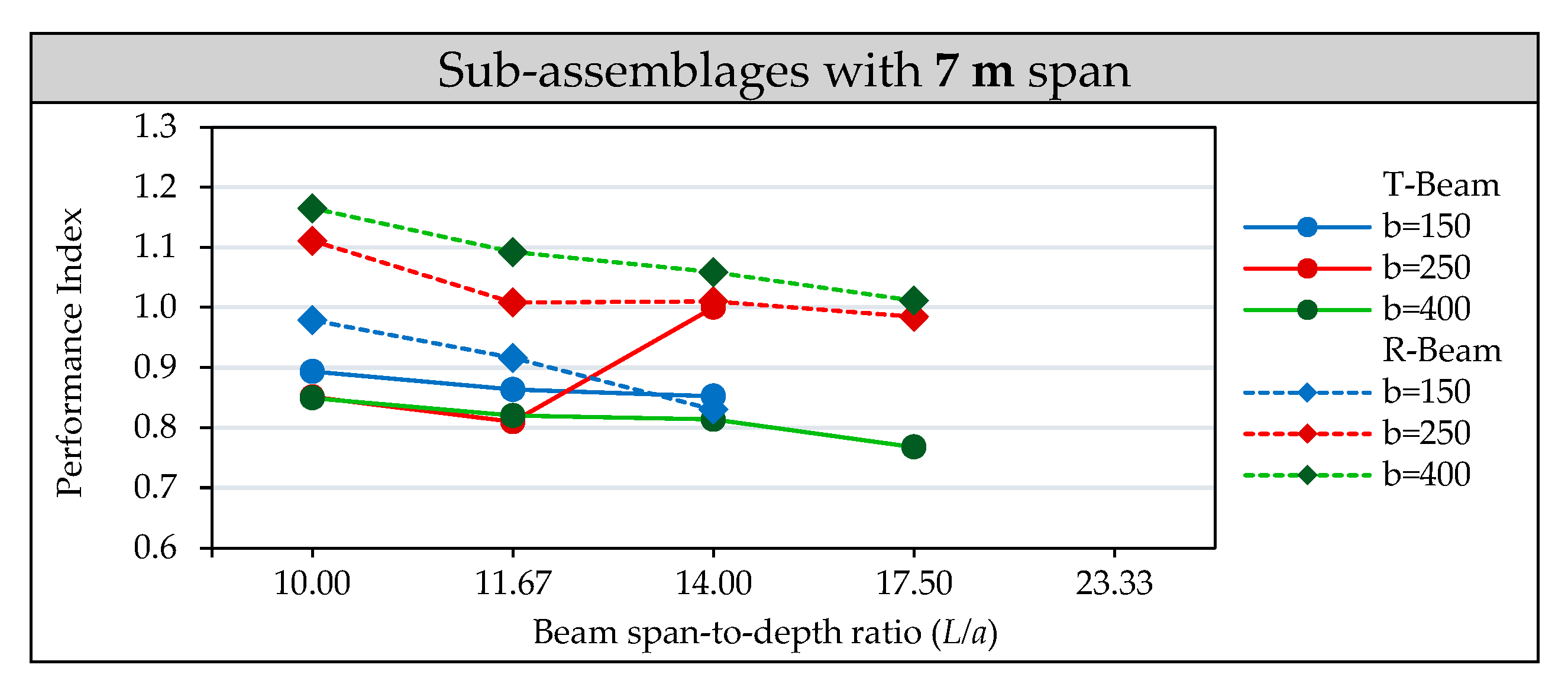
5.2.4. Performance Index
6. Conclusions
Author Contributions
Funding
Institutional Review Board Statement
Informed Consent Statement
Data Availability Statement
Acknowledgments
Conflicts of Interest
References
- Department of Defense (DoD). Design of buildings to resist progressive collapse. In Unified Facilities Criteria, UFC 4-023-03; US Department of Defense: Washington, DC, USA, 2016. [Google Scholar]
- GSA (General Services Administration). Alternate Path Analysis & Design Guidelines for Progressive Collapse Resistance; Revision 1; General Services Administration: Washington, DC, USA, 2016. [Google Scholar]
- Byfield, M.; Mudalige, W.; Morison, C.; Stoddart, E. A review of progressive collapse research and regulations. Proc. Inst. Civ. Eng.-Struct. Build. 2014, 167, 447–456. [Google Scholar] [CrossRef] [Green Version]
- Adam, J.M.; Parisi, F.; Sagaseta, J.; Lu, X. Research and practice on progressive collapse and robustness of building structures in the 21st century. Eng. Struct. 2018, 173, 122–149. [Google Scholar] [CrossRef]
- Wang, H.; Zhang, A.; Li, Y.; Yan, W. A review on progressive collapse of building structures. Open. Civ. Eng. J. 2014, 8, 183–192. [Google Scholar] [CrossRef] [Green Version]
- Abdelwahed, B. A review on building progressive collapse, survey and discussion. Case Stud. Constr. Mater. 2019, 11, e00264. [Google Scholar] [CrossRef]
- Li, B.; Yap, S.L. Experimental investigation of reinforced concrete exterior beam–column sub-assemblages for progressive collapse. ACI Struct. J. 2011, 108, 542–552. [Google Scholar]
- Yu, J.; Tan, K.H. Structural behavior of RC beam–column sub-assemblages under a middle column removal scenario. J. Struct. Eng. ASCE 2013, 139, 233–250. [Google Scholar] [CrossRef]
- Kang, S.B.; Tan, K.H.; Yang, E.H. Progressive collapse resistance of precast beam–column sub-assemblages with engineered cementitious composites. Eng. Struct. 2015, 98, 186–200. [Google Scholar] [CrossRef]
- Qian, K.; Li, B. Slab effects on the response of reinforced concrete substructures after loss of corner column. ACI Struct. J. 2012, 109, 845–855. [Google Scholar]
- Qian, K.; Li, B. Quantification of slab influences on the dynamic performance of RC frames against progressive collapse. J. Perform. Constr. Fac. ASCE 2015, 29, 04014029. [Google Scholar] [CrossRef]
- Sasani, M.; Bazan, M.; Sagiroglu, S. Experimental and analytical progressive collapse evaluation of actual reinforced concrete structure. ACI Struct. J. 2007, 104, 731–739. [Google Scholar]
- Sasani, M.; Kropelnicki, J. Progressive collapse analysis of an RC structure. Struct. Des. Tall Spec. Build. 2008, 17, 757–771. [Google Scholar] [CrossRef]
- Yi, W.J.; He, Q.F.; Xiao, Y.; Kunnath, S.K. Experimental study on progressive collapse-resistant behavior of reinforced concrete frame structures. ACI Struct. J. 2008, 105, 433–439. [Google Scholar]
- Yang, B.; Tan, K.H. Robustness of bolted-angle connections against progressive collapse: Experimental tests of beam-column joints and development of component-based models. Struct. Eng. 2013, 139, 1498–1514. [Google Scholar] [CrossRef]
- Li, B.; Tran, C.T.N.; Pan, T.C. Experimental and numerical investigations on the seismic behavior of lightly reinforced concrete beam-column joints. J. Struct. Eng. 2009, 135, 1007–1018. [Google Scholar] [CrossRef]
- Yu, J.; Tan, K.H. Experimental and numerical investigation on progressive collapse resistance of reinforced concrete beam column sub-assemblages. Eng. Struct. 2013, 55, 90–106. [Google Scholar] [CrossRef]
- Su, Y.; Tian, Y.; Song, X. Progressive collapse resistance of axially-restrained frame beams. ACI Struct. J. 2009, 106, 600–607. [Google Scholar]
- Gu, X.L.; Zhang, B.; Wang, Y.; Wang, X.L. Experimental investigation and numerical simulation on progressive collapse resistance of RC frame structures considering beam flange effects. J. Build. Eng. 2021, 42, 102797. [Google Scholar] [CrossRef]
- ACI Committee. Building Code Requirements for Structural Concrete, ACI 318-05; American Concrete Institute: Farmington Hills, MI, USA, 2005. [Google Scholar]
- Qian, L.; Li, Y.; Diao, M.; Guan, H.; Lu, X. Experimental and computational assessments of progressive collapse resistance of reinforced concrete planar frames subjected to penultimate column removal scenario. J. Perform. Constr. Facil. 2020, 34, 04020019. [Google Scholar] [CrossRef]
- Sasani, M.; Kazemi, A.; Sagiroglu, S.; Forest, S. Progressive collapse resistance of an actual 11-story structure subjected to severe initial damage. J. Struct. Eng. 2011, 137, 893–902. [Google Scholar] [CrossRef]
- Yu, J.; Tan, K.H. Analytical model for the capacity of compressive arch action of reinforced concrete sub-assemblages. Mag. Concr. Res. 2014, 66, 109–126. [Google Scholar] [CrossRef]
- Pham, A.T.; Tan, K.H. A simplified model of catenary action in reinforced concrete frames under axially restrained conditions. Mag. Concr. Res. 2017, 69, 1115–1134. [Google Scholar] [CrossRef]
- Sadek, F.; Main, J.A.; Lew, H.S.; Bao, Y. Testing and analysis of steel and concrete beam-column assemblies under a column removal scenario. J. Struct. Eng. 2011, 137, 881–892. [Google Scholar] [CrossRef] [Green Version]
- Wang, F.; Yang, J.; Shah, S. Effect of horizontal restraints on progressive collapse resistance of precast concrete beam-column framed substructures. J. Civ. Eng. 2020, 24, 879–889. [Google Scholar] [CrossRef]
- Zhou, Y.; Chen, T.; Pei, Y.; Hwang, H.J.; Hu, X.; Yi, W.; Deng, L. Static load test on progressive collapse resistance of fully assembled precast concrete frame structure. Eng. Struct. 2019, 200, 109719. [Google Scholar] [CrossRef]
- Feng, D.C.; Xie, S.C.; Li, Y.; Jin, L. Time-dependent reliability-based redundancy assessment of deteriorated RC structures against progressive collapse considering corrosion effect. Struct. Saf. 2021, 89, 102061. [Google Scholar] [CrossRef]
- Feng, D.C.; Xie, S.C.; Xu, J.; Qian, K. Robustness quantification of reinforced concrete structures subjected to progressive collapse via the probability density evolution method. Eng. Struct. 2020, 202, 109877. [Google Scholar] [CrossRef]
- Pham, A.T.; Tan, K.H. Experimental study on dynamic responses of reinforced concrete frames under sudden column removal applying concentrated loading. Eng. Struct. 2017, 139, 31–45. [Google Scholar] [CrossRef]
- Feng, D.C.; Xie, S.C.; Deng, W.N.; Ding, Z.D. Probabilistic failure analysis of reinforced concrete beam-column sub-assemblage under column removal scenario. Eng. Fail. Anal. 2019, 100, 381–392. [Google Scholar] [CrossRef]
- Feng, D.C.; Xie, S.C.; Ning, C.L.; Liang, S.X. Investigation of modeling strategies for progressive collapse analysis of RC frame structures. J. Perform. Constr. Facil. 2019, 33, 04019063. [Google Scholar] [CrossRef]
- Dat, P.X.; Tan, K.H. Experimental study of beam-slab substructures subjected to a penultimate-internal column loss. Eng. Struct. 2013, 55, 2–15. [Google Scholar]
- Dat, P.X.; Tan, K.H. Experimental response of beam-slab substructures subject to penultimate-external column removal. J. Struct. Eng. 2015, 141, 014170. [Google Scholar] [CrossRef]
- Lu, X.; Lin, K.; Li, Y.; Guan, H.; Ren, P.; Zhou, Y. Experimental investigation of RC beam-slab substructures against progressive collapse subject to an edge column-removal scenario. Eng. Struct. 2017, 149, 91–103. [Google Scholar] [CrossRef]
- Qian, K.; Li, B.; Zhang, Z. Influence of multicolumn removal on the behavior of RC floors. J. Struct. Eng. 2016, 142, 04016006. [Google Scholar] [CrossRef]
- Tan, Z.; Zhong, W.H.; Tian, L.M.; Zheng, Y.H.; Meng, B.; Duan, S.C. Numerical study on collapse-resistant performance of multi-story composite frames under a column removal scenario. J. Build. Eng. 2021, 44, 102957. [Google Scholar] [CrossRef]
- Qian, K.; Li, B. Resilience of flat slab structures in different phases of progressive collapse. ACI Struct. J. 2016, 113, 537–548. [Google Scholar] [CrossRef]
- Yu, J.; Luo, L.; Li, Y. Numerical study of progressive collapse resistance of RC beam-slab substructures under perimeter column removal scenarios. Eng. Struct. 2018, 159, 14–27. [Google Scholar] [CrossRef]
- El-Ariss, B.; El-Ariss, S. Scheme for beam progressive collapse mitigation. Int. J. Struct. Eng. 2018, 9, 175–190. [Google Scholar] [CrossRef]
- Elkholy, S.; El-Ariss, B. Increasing Robustness of Reinforced Concrete Structures under Column Losses Scenario. In Proceedings of the 9th International Structural Engineering and Construction Conference, ISEC_09, Valencia, Spain, 24–29 July 2017. [Google Scholar]
- Elkholy, S.; El-Ariss, B. Improving the robustness of reinforced concrete framed structures under sudden column losses. Int. J. Prot. Struct. 2016, 7, 282–300. [Google Scholar] [CrossRef]
- Elkoly, S.; El-Ariss, B. Progressive collapse evaluation of externally mitigated reinforced concrete beams. Eng. Fail. Anal. 2014, 40, 33–47. [Google Scholar] [CrossRef]
- Elkholy, S.; El-Ariss, B. Enhanced external progressive collapse mitigation scheme for RC structures. Int. J. Struct. Eng. 2016, 7, 63–88. [Google Scholar] [CrossRef]
- Shehada, A.; Elkholy, S.; El-Ariss, B. Numerical Progressive Collapse Analysis of RC Framed Structures. In Proceedings of the 6th World Congress on Civil, Structural, and Environmental Engineering, Virtual, 21–23 June 2021; pp. 1–8. [Google Scholar]
- Elkholy, S.; Shehada, A.; El-Ariss, B. Numerical Simulation as Alternative to Progressive Collapse Destructive Tests. In Proceedings of the 8th Edition of the Zero Energy Mass Custom Home (ZEMCH 2021), Dubai, United Arab Emirates, 26–28 October 2021; pp. 954–961. [Google Scholar]
- Elsanadedy, H.M.; Abadel, A. High-fidelity FE models for assessing progressive collapse robustness of RC ordinary moment frame (OMF) buildings. Eng. Fail. Anal. 2022, 136, 106228. [Google Scholar] [CrossRef]
- Iribarren, B.S.; Berke, P.; Bouillard, P.; Vantomme, J.; Massart, T.J. Investigation of the influence of design and material parameters in the progressive collapse analysis of RC structures. Eng. Struct. 2011, 33, 2805–2820. [Google Scholar] [CrossRef] [Green Version]
- Elkholy, S.; Shehada, A.; El-Ariss, B. Effect of Beam Design on Progressive Collapse Resistance of RC. In Proceedings of the 6th World Congress on Civil, Structural, and Environmental Engineering;(CSEE’21), Virtual Conference, Lisbon, Portugal, 21–23 June 2021. (Due to COVID’19 pandemic). [Google Scholar] [CrossRef]
- American Concrete Institute Committee, ACI-318. Building Code Requirements for Structural Concrete: (ACI 318-14); and Commentary (ACI 318R-14); American Concrete Institute: Farmington Hills, MI, USA, 2014. [Google Scholar]
- STRUCTUREPOINT, spSlab/spBeam User Manual, v5.50, Formerly the Engineering Software Group of the Portland Cement Association (PCA). Available online: https://structurepoint.org/pdfs/manuals/spSlab-Manual.pdf (accessed on 10 April 2022).
- SeismoStruct 2021—A Computer Program for Static and Dynamic Nonlinear Analysis of Framed Structures. Available online: https://seismosoft.com/ (accessed on 1 November 2021).
- El-Ariss, B.; Elkholy, S.; Shehada, A. Benchmark Numerical Model for Progressive Collapse Analysis of RC Beam-Column Sub-Assemblages. Buildings 2022, 12, 122. [Google Scholar] [CrossRef]
- American Society of Civil Engineers. Minimum Design Loads and Associated Criteria for Buildings and Other Structures; American Society of Civil Engineers: Reston, VA, USA, 2022. [Google Scholar]


| Beam Dimensions, Varying Design Options (mm) | Beam Span (m) | Thickness of Slab (mm) | All Columns | |||||
|---|---|---|---|---|---|---|---|---|
| Width (b) | Height (a) | Width (b) | Height (a) | Width (b) | Height (a) | Dimensions and Detailing (mm) | ||
| 150 | 300 | 250 | 300 | 400 | 300 | 5, 6, and 7 | varies from 125 to 205 | 400 × 400 8#32 |
| 150 | 400 | 250 | 400 | 400 | 400 | |||
| 150 | 500 | 250 | 500 | 400 | 500 | |||
| 150 | 600 | 250 | 600 | 400 | 600 | |||
| 150 | 700 | 250 | 700 | 400 | 700 | |||
| Material | Material Properties | |
|---|---|---|
| Steel reinforcement | Elastic modulus (MPa) | 200,000 |
| Yield strength (MPa) | 420 | |
| Fracture strain (%) | 6.5–7.0 | |
| Concrete | Compressive strength (MPa) | 35 |
| Mean tensile strength (MPa) | 2.2 | |
| Modulus of elasticity (MPa) | 27,806 | |
| Span (m) | Sub-Assemblage Beam Varying Design Options bxa (mm) | Slab Thickness, h (mm) | Sub-Assemblage Beam Reinforcement of the Varying Design Options | |||||||
|---|---|---|---|---|---|---|---|---|---|---|
| Bottom/Sagging Reinforcement | Top/Hogging Reinforcement | |||||||||
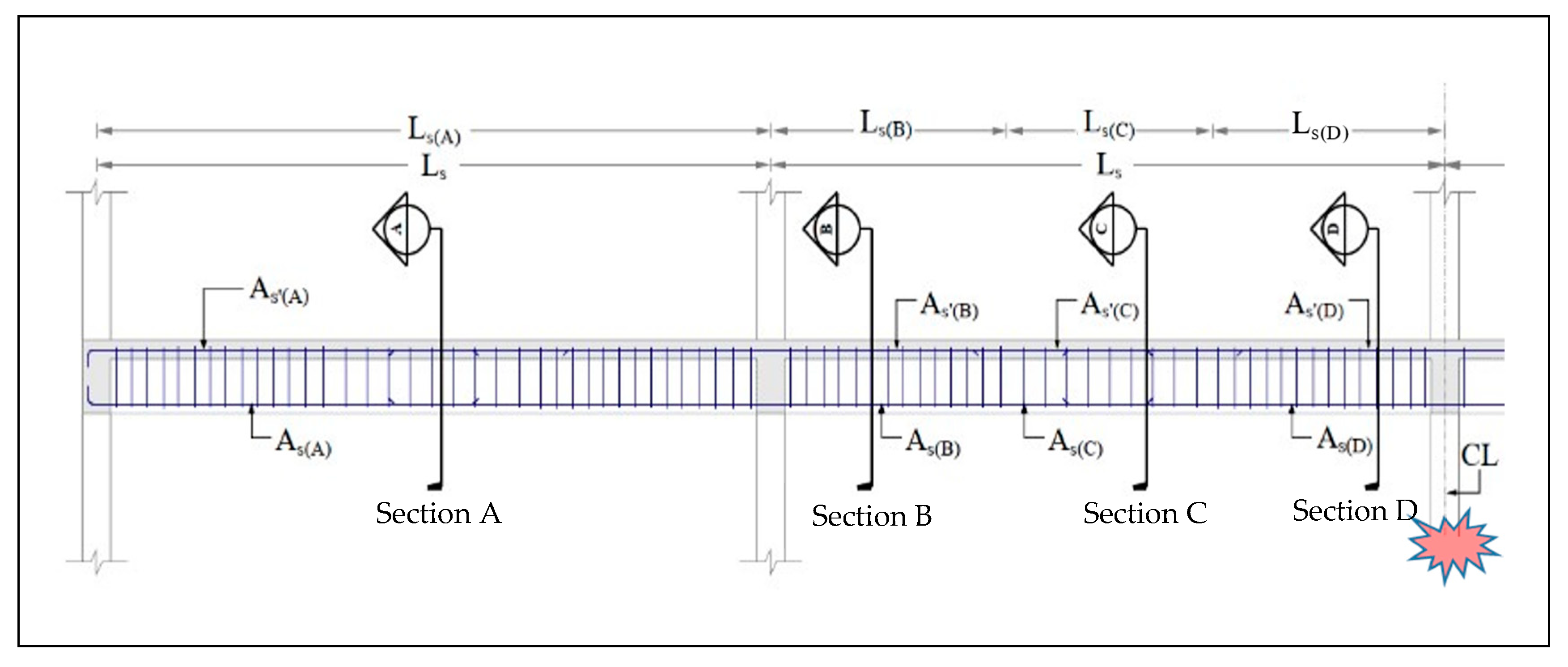
| Section A * | Section B * | Section C * | Section D * | Section A * | Section B * | Section C * | Section D * | |||
| 5 | 150 × 300 | 145 | 3 #13 | 2#13 | 2#13 | 2#13 | - | 3 #19 | - | 3 #16 |
| 150 × 400 | 125 | 3 #13 | 2#13 | 2#13 | 2#13 | - | 4 #16 | - | 4 #16 | |
| 150 × 500 | 125 | 3 #13 | 2 #13 | 2 #13 | 2 #13 | - | 4 #16 | - | 4 #16 | |
| 150 × 600 | 125 | 2 #13 | 2 #13 | 2 #13 | 2 #13 | - | 5 #13 | - | 5 #13 | |
| 150 × 700 | 125 | 2 #19 | 2 #13 | 2 #13 | 2 #13 | - | 5 #10 | - | 5 #10 | |
| 250 × 300 | 140 | 4 #13 | 3 #13 | 3 #13 | 3 #13 | - | 5 #16 | - | 4 #16 | |
| 250 × 400 | 125 | 3 #13 | 3 #13 | 3 #13 | 3 #13 | - | 4 #16 | - | 4 #13 | |
| 250 × 500 | 125 | 4 #13 | 2 #13 | 2 #13 | 2 #13 | - | 5 #13 | - | 5 #13 | |
| 250 × 600 | 125 | 3 #13 | 2 #13 | 2 #13 | 2 #13 | - | 6 #13 | - | 6 #13 | |
| 250 × 700 | 125 | 2 #19 | 5 #10 | 5 #10 | 5 #10 | 4 #13 | 4 #13 | 4 #13 | 4 #13 | |
| 400 × 300 | 135 | 4 #13 | 3 #13 | 3 #13 | 3 #13 | - | 5 #16 | - | 5 #16 | |
| 400 × 400 | 125 | 4 #13 | 3 #13 | 3 #13 | 3 #13 | - | 5 #13 | - | 5 #13 | |
| 400 × 500 | 125 | 4 #13 | 3 #13 | 3 #13 | 3 #13 | - | 5 #13 | - | 5 #13 | |
| 400 × 600 | 125 | 3 #13 | 3 #13 | 3 #13 | 3 #13 | - | 6 #13 | - | 6 #13 | |
| 400 × 700 | 125 | 3 #13 | 5 #10 | 5 #10 | 5 #10 | - | 4 #13 | - | 4 #13 | |
| 6 | 150 × 300 | section did not meet the design requirements of the ACI 318-14 code | ||||||||
| 150 × 400 | 170 | 3 #13 | 2 #13 | 2 #13 | 2 #13 | - | 5 #13 | - | 5 #13 | |
| 150 × 500 | 150 | 4 #13 | 3 #13 | 3 #13 | 3 #13 | - | 5 #16 | - | 5 #13 | |
| 150 × 600 | 150 | 4 #13 | 3 #13 | 3 #13 | 3 #13 | - | 6 #13 | - | 4 #13 | |
| 150 × 700 | 150 | 3 #13 | 3 #13 | 3 #13 | 3 #13 | - | 2 #19 | - | 4 #13 | |
| 250 × 300 | section did not meet the design requirements of the ACI 318-14 code | |||||||||
| 250 × 400 | 160 | 5 #13 | 4 #13 | 4 #13 | 4 #13 | - | 6 #16 | - | 5 #16 | |
| 250 × 500 | 150 | 4 #13 | 4 #13 | 4 #13 | 4 #13 | - | 5 #16 | - | 5 #13 | |
| 250 × 600 | 150 | 4 #13 | 3 #13 | 3 #13 | 3 #13 | - | 6 #13 | - | 4 #13 | |
| 250 × 700 | 150 | 4 #13 | 3 #13 | 3 #13 | 3 #13 | - | 5 #13 | - | 2 #19 | |
| 400 × 300 | section did not meet the design requirements of the ACI 318-14 code | |||||||||
| 400 × 400 | 150 | 5 #13 | 4 #13 | 4 #13 | 4 #13 | - | 4 #19 | - | 5 #13 | |
| 400 × 500 | 150 | 5 #13 | 4 #13 | 4 #13 | 4 #13 | - | 5 #16 | - | 5 #13 | |
| 400 × 600 | 150 | 5 #13 | 3 #13 | 3 #13 | 3 #13 | - | 5 #16 | - | 5 #13 | |
| 400 × 700 | 150 | 5 #13 | 3 #13 | 3 #13 | 3 #13 | - | 5 #16 | - | 2 #19 | |
| 7 | 150 × 300 | section did not meet the design requirements of the ACI 318-14 code | ||||||||
| 150 × 400 | section did not meet the design requirements of the ACI 318-14 code | |||||||||
| 150 × 500 | 190 | 4 #13 | 3 #13 | 3 #13 | 3 #13 | - | 4 #19 | - | 6 #13 | |
| 150 × 600 | 170 | 5 #13 | 3 #13 | 3 #13 | 3 #13 | - | 4 #19 | - | 6 #13 | |
| 150 × 700 | 170 | 4 #13 | 2 #13 | 2 #13 | 2 #13 | - | 5 #16 | - | 5 #13 | |
| 250 × 300 | section did not meet the design requirements of the ACI 318-14 code | |||||||||
| 250 × 400 | 200 | 3 #13 | 3 #13 | 3 #13 | 3 #13 | - | 6 #13 | - | 4 #13 | |
| 250 × 500 | 180 | 6 #13 | 4 #13 | 4 #13 | 4 #13 | - | 5 #19 | - | 5 #16 | |
| 250 × 600 | 170 | 5 #13 | 4 #13 | 4 #13 | 4 #13 | - | 4 #19 | - | 4 #19 | |
| 250 × 700 | 170 | 5 #13 | 4 #13 | 4 #13 | 4 #13 | - | 5 #16 | - | 5 #13 | |
| 400 × 300 | section did not meet the design requirements of the ACI 318-14 code | |||||||||
| 400 × 400 | 190 | 5 #13 | 4 #13 | 4 #13 | 4 #13 | - | 6 #16 | - | 5 #16 | |
| 400 × 500 | 170 | 6 #13 | 5 #13 | 5 #13 | 5 #13 | - | 5 #19 | - | 5 #16 | |
| 400 × 600 | 170 | 5 #16 | 5 #13 | 5 #13 | 5 #13 | - | 4 #19 | - | 5 #16 | |
| 400 × 700 | 170 | 5 #16 | 4 #13 | 4 #13 | 4 #13 | - | 4 #19 | - | 5 #16 | |
Publisher’s Note: MDPI stays neutral with regard to jurisdictional claims in published maps and institutional affiliations. |
© 2022 by the authors. Licensee MDPI, Basel, Switzerland. This article is an open access article distributed under the terms and conditions of the Creative Commons Attribution (CC BY) license (https://creativecommons.org/licenses/by/4.0/).
Share and Cite
Elkholy, S.; Shehada, A.; El-Ariss, B. Effects of Floor System on Progressive Collapse Behavior of RC Frame Sub-Assemblages. Buildings 2022, 12, 737. https://doi.org/10.3390/buildings12060737
Elkholy S, Shehada A, El-Ariss B. Effects of Floor System on Progressive Collapse Behavior of RC Frame Sub-Assemblages. Buildings. 2022; 12(6):737. https://doi.org/10.3390/buildings12060737
Chicago/Turabian StyleElkholy, Said, Ahmad Shehada, and Bilal El-Ariss. 2022. "Effects of Floor System on Progressive Collapse Behavior of RC Frame Sub-Assemblages" Buildings 12, no. 6: 737. https://doi.org/10.3390/buildings12060737