Article

Research on Frost Heaving Characteristics of Hydraulic Tunnels’ Wall Rock in Cold Regions Based on Phase Transition and Water-Heat-Stress Coupling

1
College of Water and Architectural Engineering, Shihezi University, Shihezi 832000, China
2
Department of Architectural Engineering, Zhejiang Tongji Vocational College of Science and Technology, Hangzhou 311200, China
3
Department of Civil Engineering, Zhejiang University City College, Hangzhou 310015, China
4
College of Civil Engineering and Architecture, Zhejiang University, Hangzhou 310058, China
*
Author to whom correspondence should be addressed.
Buildings 2022, 12(7), 1026; https://doi.org/10.3390/buildings12071026
Submission received: 12 June 2022 / Revised: 6 July 2022 / Accepted: 13 July 2022 / Published: 15 July 2022
(This article belongs to the Section Building Materials, and Repair & Renovation)

Abstract

:
In order to study the problem of frost damage to wall rock caused by hydraulic tunnels’ phase transition between water and ice at low temperatures in cold regions, a three-field coupling governing equation considering temperature, seepage and stress was deduced. Taking a water conveyance tunnel in Xinjiang as the research object, a three-dimensional frost heaving finite element model was established based on the deduced coupling equations using finite element software. By numerically simulating the process of frost heaving, the spatial distribution and variation law of the frozen area and frost heaving force were obtained. The present study showed that the frozen area of wall rock at the tunnel entrance is spatially distributed in a long-necked funnel shape, and the frost depth of the section gradually decreases along the depth of the tunnel. Due to the hysteresis of heat conduction, the peak point of the maximum freezing depth of wall rock appears after the minimum ambient temperature. The circumferential distribution law of frost heaving force in wall rock remains consistent with the depth, that is, the maximum frost heaving tension occurs at the arch top and arch bottom and decreases to zero in the circumferential direction, and then it turns into the frost heaving pressure which gradually increases to the maximum at the arch waist. Along the depth, at 20 m away from the tunnel entrance, the frost heaving force at the arch top, arch waist and arch bottom is divided into a steep decline zone and a slow decline zone. After being frozen for 30 to 150 days, the growth rate of the absolute value of the maximum frost heaving force at the arch top and arch bottom is about 1.5 times that of the arch waist. The frost heaving force has greater influence on the arch top and arch bottom than on the arch waist.

1. Introduction

Permafrost is widely distributed in China. Permafrost and seasonal permafrost account for 21.5% and 53.5% of the land area, respectively, making it the third largest permafrost country in the world [1,2]. With the implementation of the One Belt One Road initiative, more and more water conservancy projects are being constructed in the cold regions of China. However, the special climate environment of tunnels in cold regions causes significant changes in the temperature of wall rock and the inside of the tunnel, seepage field, and stress field, thereby causing the freeze and thaw of the pore water in the wall rock of the frozen area. The repeated frost heaving of the wall rock leads to an increase in fractures and the forming of water channels. Phase transition between water and ice at low temperatures causes volume expansion by 9%, which leads to additional frost heaving force in the tunnel. This is one of the important reasons for the existence of frost damage problems such as tunnel seepage, icing and hanging ice in the tunnel, cracking, crushing and spalling of tunnel wall rock, and lining in hydraulic tunnels in cold regions [3,4], which seriously endanger the construction and operation of tunnels. In order to ensure the normal construction and operation of the hydraulic tunnels in cold regions, it is of great significance to study the frost heaving characteristics of hydraulic tunnels’ wall rock in cold regions.
In the study of water-ice phase transition and multi-field coupling of the frozen rock in cold regions, G. P. Brovka et al. [5] derived a nonlinear heat conduction equation considering the phase transition between water and ice for the numerical calculation of the freeze-thaw temperature field. Tan Xianjun et al. [6,7] established a water-heat coupling model containing the phase transition between water and ice, and studied the temperature field distribution in the tunnel and the size of the freeze-thaw circle. Zhang Xudong et al. [8] established a water-heat coupling model to describe the freezing process, and obtained the dynamic variation law of the freezing depth of rock mass under the water-heat change. Yared W. Bekele et al. [9] established a water-heat-stress coupling numerical model of frozen soil based on IGA, which took the stress field into consideration but ignored the phase transition between water and ice in the frozen soil analysis. Li Guofeng et al. [10] combined the model of phase transition between water and ice and the model of water-heat-stress coupling through the secondary development of FLAC3D software, and established a simple coupling model of water-ice phase transition and water-heat-stress. Huang Shibing et al. [11] not only deduced the low-temperature water-heat coupling equations, but also studied the evolution of critical coupling parameters of rocks. Wu Di et al. [12] established a water-heat-stress coupling model and applied it to study the stability and durability of subway tunnels. The above results have gradually improved the coupling analysis of the water-ice phase transition and separate temperature field, water-heat coupling and water-heat-stress coupling, and have been applied to engineering practice analysis. However, there are still very few theoretical models and practical applications for hydraulic tunnels in cold regions. By using the methods of theoretical derivation, numerical simulation, and on-site monitoring, many scholars have achieved fruitful results on the frost heaving characteristics of tunnels in cold regions. For example, Xia Caichu et al. [13,14,15] developed different formulas to calculate different maximum freezing depths considering multiple influencing factors such as lining, insulation layer, unfrozen water content in the frozen wall rock, thermal conductivity, and freezing index. However, these formulas cannot fully describe the transient changes in the freezing depth. Feng Qiang and Lv Zhitao et al. [16,17,18] respectively deduced the elastoplastic analytical solution of the frost heaving force in the wall rock of the isotropic and anisotropic tunnels in cold regions. Zhu Yimo et al. [19] deduced the frost heaving force of non-circular tunnels and the analytical solutions for displacement. However, these theories are mainly based on two-dimensional plane analysis. Yet, at present, no scholar has conducted the derivation of the three-field coupling governing equitation considering phase transition temperature, seepage and stress in order to solve the hydraulic tunnel’s phase transition between water and ice at low temperatures in cold regions, which is caused by frost damage of wall rock, not to mention conducting 3D simulation analysis of the frost heaving process of hydraulic tunnels in cold regions using the finite element of the derived coupling governing equitation, based on the actual project.
In view of this, firstly based on thermodynamics, fluid mechanics, continuum mechanics, partial condensation potential theory and Terzaghi’s Principle, this study combined previous conclusions and derived the basic governing equations for the coupling of the temperature field, seepage field, and stress field with consideration of the phase transition between water and ice at low temperatures. Then, based on the derived coupling governing equation, a three-dimensional frost heaving finite element model of a hydraulic tunnel in Xinjiang was established by using finite element software, and the frost heaving process of the project was simulated. By comparing the measured freezing depth and the frost heaving force with the finite element simulation results, the reliability of the finite element simulation was verified. Finally, according to the finite element simulation results, the spatial distribution and variation law of wall rock freezing zone and frost heaving force are analyzed, which can provide reference for the design, construction and operation of hydraulic tunnels in cold regions.

2. Water-Heat-Stress Coupled Control Equations Considering Water-Ice Phase Transition

2.1. Basic Assumptions

In order to simplify the model and facilitate the derivation of the formula, the following assumptions must be made for the derivation of the water-heat-stress coupled control equations with consideration of the low-temperature water-ice phase transition:
(1)
The rock mass is an isotropic continuous medium;
(2)
The rock mass can be considered as an ideal elastic material;
(3)
The porosity of the rock mass is constant and always in a saturated state;
(4)
The heat conduction of the rock mass satisfies the Fourier Law, and the seepage flow satisfies the Darcy Law;
(5)
The deformation of the rock mass is small, which conforms to the conditions of using the Terzaghi Effective Stress Principle.
According to the above assumptions, saturated rock mass is composed of rock skeleton, water and ice at a low temperature. The temperature field, seepage field and stress field of surrounding rocks in cold regions can be assumed and deduced according to their corresponding physical parameters. Suppose the volume contents of the skeleton, water and ice are θs, θw and θi, respectively, and the three parameters satisfy the following equation:
θ s + θ w + θ i = 1

2.2. Control Equation of Temperature Field Considering Phase Transition

In the process of deriving the control equation for temperature field, due to the different thermodynamic properties of the liquid water and the solid ice and skeleton, the energy equations of solid and liquid need to be defined separately.
According to the Euler Theory, taking the internal unit body of the frozen rock mass as Ω, the outer surface area as A, and the exterior normal direction as n , the heat injection from the outside per unit time of the rock mass can be expressed as
A q s n dA = Ω q s d Ω
where qs is the heat flux density of solid.
The amount of heat injected by the internal heat source per unit of time of the control body is
Ω Q s d Ω
where Qs is the heat generated by the internal heat source.
The latent heat of phase transition when the ice in the frozen rock body turns into water is
Ω ρ w L f θ w T d Ω
where ρw is the density of water, Lf is the latent heat of water-ice phase transition and θw is the volume fraction of water.
The thermal energy required to change the temperature of the control body by the variation T is
Ω t ( ρ s C s T ) d Ω
where ρs and Cs are the density and specific heat capacity of the solid medium, respectively.
Therefore, the energy equation in the integral form of the solid medium is
Ω [ t ( ρ s C s T ) + q s ( Q s ρ w L f θ w T ) ] d Ω = 0
Since the integrand is continuous and derivable, the energy equation of the solid part can be expressed as
t ( ρ s C s T ) + q s Q s + ρ w L f θ w T = 0
Similarly, the energy equation of the liquid part can be expressed as
t ( ρ w C w T ) + q w Q w + ( ν w ) ( ρ w C w T ) = 0
where ρw and Cw are the density and specific heat capacity of water, respectively; qw is the heat flux density of water, Qw is the amount of heat change of water caused by the heat change inside the rock mass, and vw is the seepage velocity of water.
Combining Equations (7) and (8), the total energy equation of the rock mass can be obtained as
C T t + ρ w L f θ w T + q + [ ( ν w ) ( ρ w C w T ) ] = Q
where C is the equivalent specific heat capacity, q is the heat flux density, Q is the amount of heat change in the control body caused by the change in the internal heat of surrounding rocks in the frozen area.
The heat flux density can be described using the Fourier Law [20], and then the control equation of the temperature field considering the water-ice phase transition can be expressed as
C T t + ρ w L f θ w T + ( λ T n ) + [ ( ν w ) ( ρ w C w T ) ] = Q
where λ is the equivalent thermal conductivity.
The control equation of the temperature field of surrounding rocks in the unfrozen area and the frozen area is consistent with the structure of the frozen area, except that there is no term of phase transition latent heat. Therefore, the control equation of the temperature field of the surrounding rocks in the unfrozen area is
C T t + ( λ T n ) + [ ( ν w ) ( ρ w C w T ) ] = Q
According to the literature [21], the equivalent specific heat capacity and thermal conductivity of the low-temperature water-ice phase transition can be calculated using the apparent heat capacity method. Assuming that the phase transition occurs in a temperature range near Tm (Tm ± ΔΤ), the equivalent specific heat capacity and thermal conductivity can be expressed as
C = { C f , T < ( T m Δ T ) L f 2 Δ T + C f + C u 2 , ( T m Δ T ) C u , T > ( T m + Δ T ) T ( T m + Δ T )
λ = { λ f , T < ( T m Δ T ) λ f + λ u λ f 2 Δ T [ T ( T m Δ T ) ] , ( T m Δ T ) T ( T m + Δ T ) λ u , T > ( T m + Δ T )
where Cf and Cu are the specific heat capacity of surrounding rocks when the water is frozen and unfrozen, respectively, and λf and λu are the thermal conductivity of surrounding rocks when the water is frozen and unfrozen, respectively.

2.3. Control Equation of Seepage Field Considering Phase Transition

According to the Euler Theory, the internal unit body of the frozen rock mass is taken as Ω, the outer surface area as A, the exterior normal direction as n and any one of the face elements on the outer surface as dA. If the flow velocity through dA is vw, then the mass of fluid passing through the surface element dA per unit of time is ρwvWd· n dA, and the total amount of fluid passing through the outer surface area A can be obtained as
A ρ w ν w n dA
Due to the change of density function, water content and ice content caused by phase transition and unsteady heat flow varies with time, the rate of mass gain in the entire control body Ω is:
Ω ( ρ w θ w ) t d Ω + Ω ( ρ i θ i ) t d Ω
where ρi is the density of ice.
The intensity of the seepage source in the control body is q w , and the mass of the fluid produced by the source in the control body Ω per unit of time is
Ω ρ w q w d Ω
According to the law of conservation of mass, the change in the mass of fluid in the control body is equal to the difference between inflow and outflow, i.e.,
Ω ( ρ w θ w ) t d Ω + Ω ( ρ i θ i ) t d Ω = Ω ρ w q w d Ω A ρ w ν w n dA
Integrating Equation (17) according to the Gauss formula, its differential form can be obtained as
( ρ w θ w ) t + ( ρ i θ i ) t + ( ρ w ν w ) = ρ w q w
Introducing the Darcy Law and considering the temperature effect and segregation potential effect of the water-ice phase transition, the Darcy Law can be expressed as [22]
v w = k w μ w ( p + ρ w g z ) + ( S P 0 D T ) T
where kw is the permeability tensor, μw is the hydrodynamic viscosity coefficient, p is the pore water pressure, g is the acceleration of gravity, SP0 is the segregation potential of water heat migration and DT is the diffusivity of water under the action of temperature difference.
Therefore, substituting Equation (19) into Equation (18), the control equation of the seepage field considering the phase transition and water migration can be obtained as:
( ρ w θ w ) t + ( ρ i θ i ) t + [ ρ w k w μ w ( p + ρ w g ) ρ w ( S P 0 D T ) T ] = ρ w q w

2.4. Control Equation of Stress Field Considering Phase Transition

The static equilibrium equation of the rock mass is
σ i j , j + ρ e f i = 0
According to the Terzaghi Effective Stress Principle, the total stress increment of the rock mass caused by low-temperature phase transition is [23]
σ i j = σ i j ( α w p w + α i p i ) δ i j
where σij is the total stress tensor, σ i j is the effective stress tensor, pw and pi are the pore water pressure and pore ice pressure, respectively, αw and αi are the effective increment coefficients of water and ice, respectively, and δij is the Kronecker symbol. When i = j, δij = 1; when i ≠ j, δij = 0.
Therefore, the static equilibrium equation considering the effective stress is expressed as
[ σ i j ( α w p w + α i p i ) δ i j ] , j + ρ e f i = 0
Under thermoelastic conditions, the total strain of the rock mass is equal to the sum of elastic strain and thermal strain, i.e.,
ε = ε i j e + ε i j T
The thermal strain is expressed as
ε k l T = β s ( T s T s 0 ) δ k l
where βs is the thermal expansion coefficient of the rock mass, Ts and Ts0 are the temperature and reference temperature of the rock mass, respectively, and δkl is the Kronecker symbol.
Therefore, the physical equation of stress in tensor form can be expressed as
σ i j = D ε k l e
Substituting Equation (25) into Equation (26), the effective stress in tensor form can be obtained as
σ i j = D [ ε k l β s ( T s T s 0 ) δ k l ]
Substituting Equation (27) into Equation (22), the thermoelastic equilibrium equation considering water-ice phase transition can be obtained as
{ D [ ε k l β s ( T s T s 0 ) δ k l ] ( α w p w + α i p i ) δ i j } , j + ρ e f i = 0

2.5. Initial Conditions and Boundary Conditions

The initial condition of surrounding rocks is the initial state of the equilibrium of temperature, water pressure and ground stress.
{ T | t = 0 = T ( x , y , z ) p | t = 0 = p ( x , y , z ) P | t = 0 = P ( x , y , z )
where T(x,y,z), p(x,y,z), and P(x,y,z) are the temperature function, water pressure function and ground stress function, respectively.
The temperature boundary conditions include the fixed boundary (Dirichlet boundary) and the convection boundary (Neumann boundary).
{ T = C , Dirichlet λ T n = q ( t ) , Neumann
where C is a known constant, which is related to the ground temperature at the buried depth, and q(t) is the heat flux density.
The seepage boundary condition is [24]
{ n k η ( P + ρ w g H g ) = 0 q n ( x , y , z ) = k h n
where k is the permeability, η is the viscosity coefficient of water, Hg is the gravity head and qn is the boundary flow. When the boundary is separated by water, qn = 0.
The stress boundary is mainly reflected in the displacement limit, and the normal constraint acts on the limit surface.
The basic coupled control equations of the temperature field, seepage field, and stress field considering low-temperature water-ice phase transition are shown as Equations (11), (20) and (28), respectively. Based on the above equations and the specific initial and boundary conditions, the temperature, seepage and stress fields under frost heaving force of surrounding rocks can be solved.

3. Analysis of On-Site Monitoring Results of Frozen Area and Frost Heaving Force of Tunnels in Cold Regions

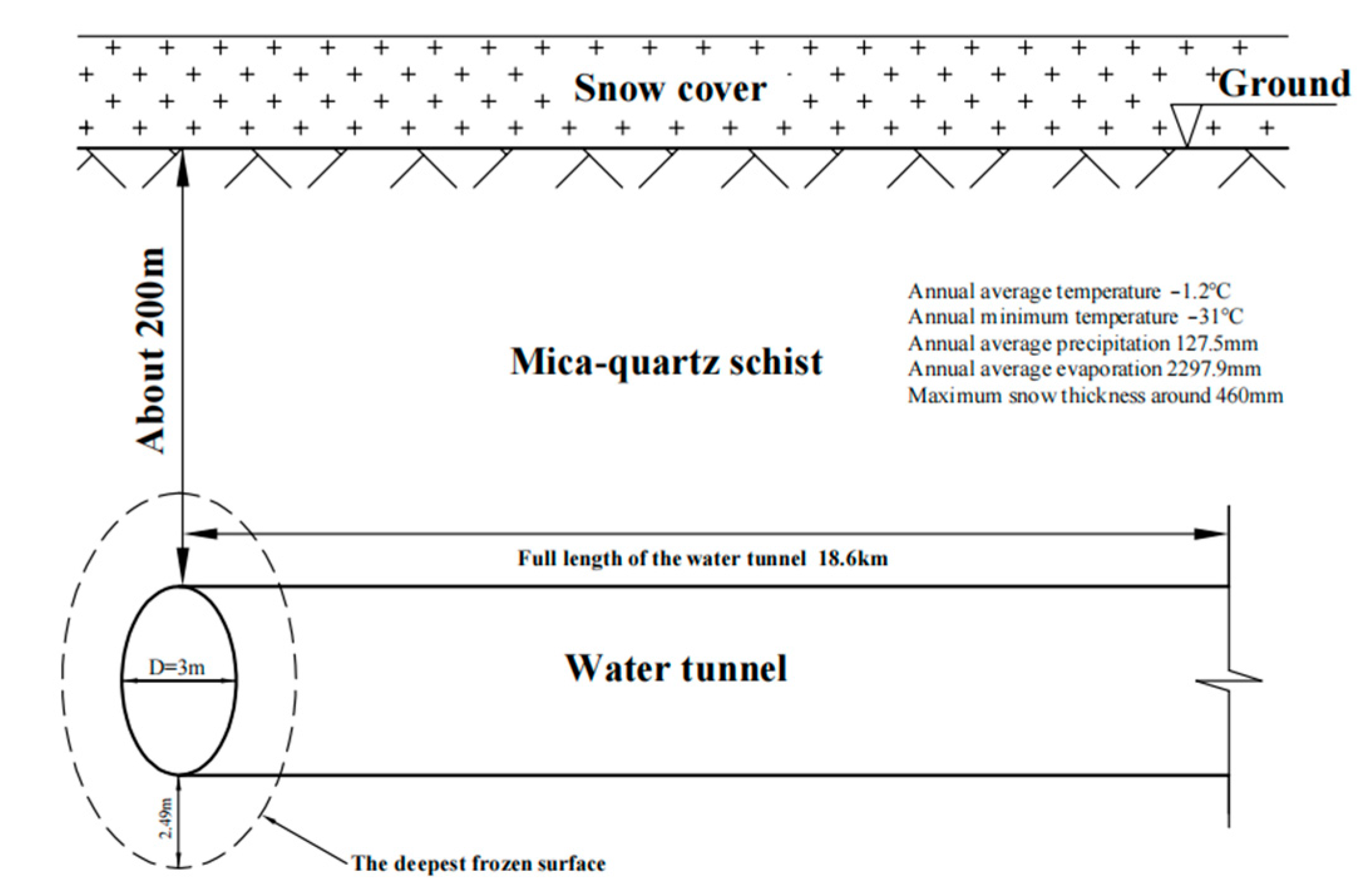
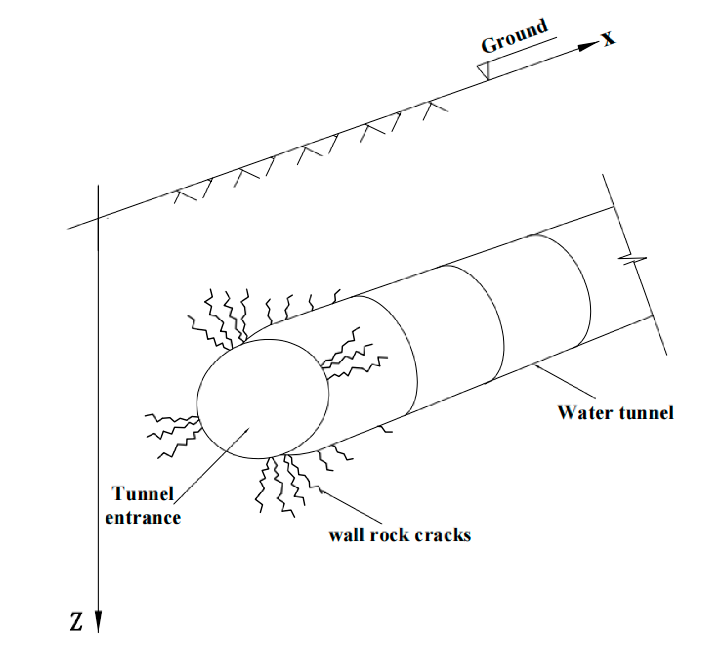
3.1. Project Overview

This study took an underground free surface flow water conveyance tunnel of a hydropower station in Xinjiang as the research object. The water conveyance tunnel is 18.6 km in length, the excavation section is circular, the inner diameter of the tunnel is 3 m, the buried depth of the tunnel entrance is nearly 200 m, the rock mass is mica quartz schist, and the category of the wall rock is Type IV. The area where the tunnel is located belongs to the periglacial and tectonic erosion mountains, which is a typical tunnel project in cold regions. The tunnel has been in a low-temperature state for a long time. The perennial mean temperature is −1.2 °C, the lowest temperature in one month can reach −31 °C, the perennial average precipitation is 127.5 mm, the annual average evaporation is 2297.9 mm, the maximum snow thickness is approximately 460 mm, and the maximum frozen depth is 2.49 m. The working condition schematic diagram of the project is shown in Figure 1. The on-site monitoring results showed that the leakage of the lining at the entrance section of the tunnel caused frost heaving, and the frozen phenomenon in the tunnel was serious, which affected the construction and operation of the tunnel. There were more than 120 frozen points along the axis of the tunnel, and the degree of freezing decreased along the depth.

3.2. Analysis of On-Site Monitoring Results of Frozen Area and Frost Heaving Force

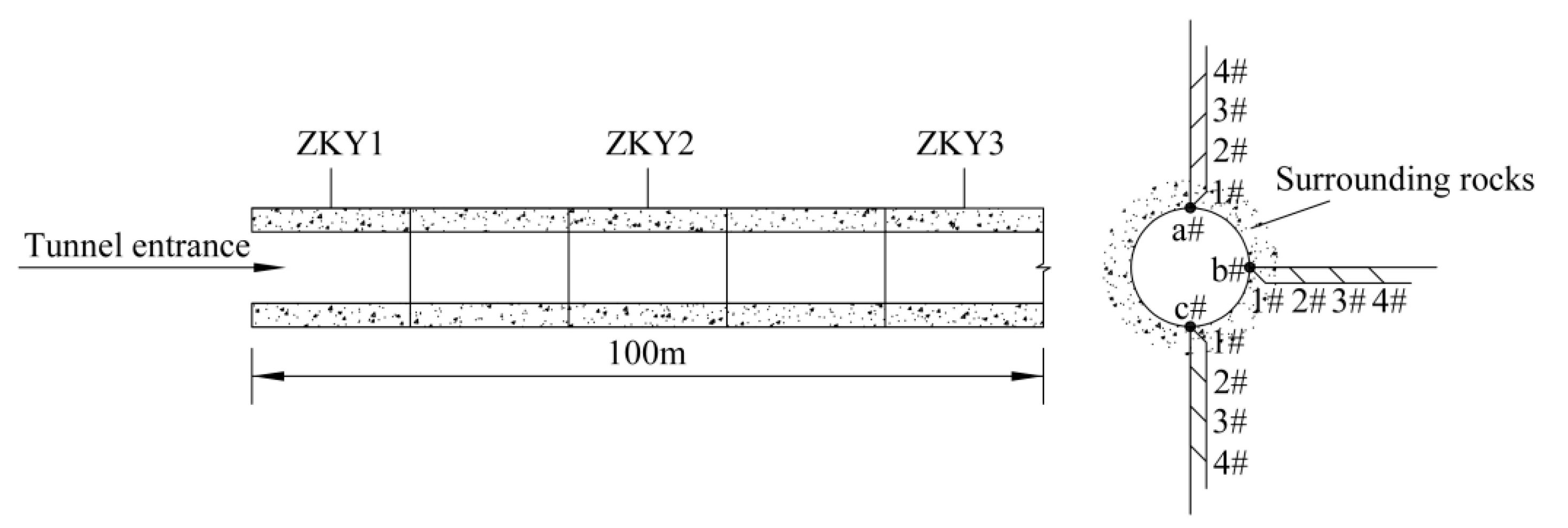
3.2.1. On-Site Monitoring Scheme

Because the entrance section of the tunnel is affected by the excavation, the stress and seepage pores of the entrance section are first redistributed and reach a new equilibrium. In the entrance section of the tunnel, the frost heaving phenomenon of wall rock is especially common. Therefore, this paper took 100 m of the tunnel entrance section (pile number ZK300 + 940 to ZK301 + 040) as the research object to monitor the relevant data, and the on-site monitoring layout is shown in Figure 2. A temperature monitoring station was set up at the tunnel entrance to monitor the changes in the ambient temperature at the site of the tunnel, which were further used as the temperature boundary for finite element calculation. In addition, the temperature and stress monitoring sections ZKY1, ZKY2, and ZKY3 were respectively set up at 10 m, 50 m, and 90 m away from the entrance of the tunnel. The four positions of the temperature measuring element points 1#, 2#, 3#, 4# were located in the arch waist, arch top, arch bottom of the tunnel wall, and the place 1 m, 2 m, 3 m away from the tunnel wall, respectively. The stress and strain measurement points in the section a#, b#, c# were set up at the contact points between the wall and lining of wall rock at the arch top, arch waist, and arch bottom, respectively. The stress and strain measurement points were placed alternately with temperature elements.

3.2.2. Analysis of the Variation Law of Frozen Area and Frost Heaving Force
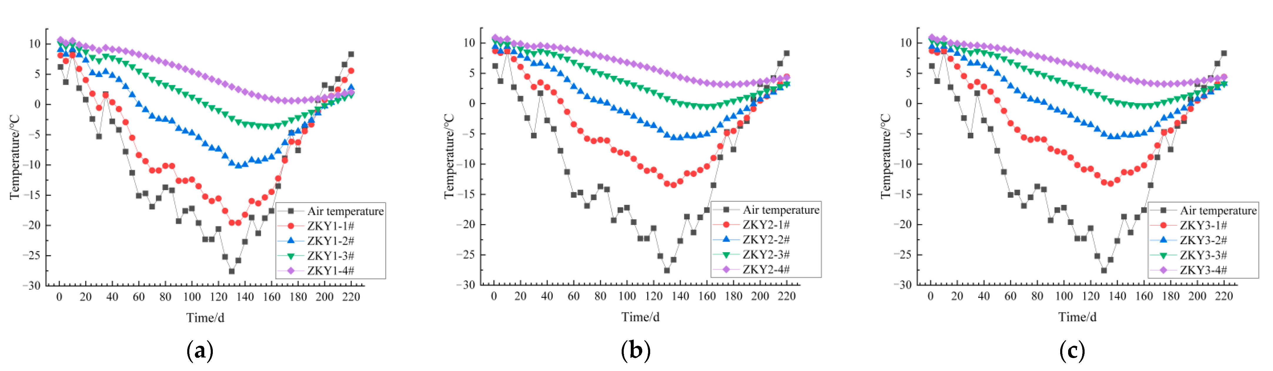
The temperature monitoring change curve for a total of 220 days from 15 September 2018 to 22 April 2019 is shown in Figure 3. From Figure 3, it can be seen that:
(1)
In the same section, the temperature changes at different depths from the axis of the cave were different. The closer to the axis of the cave, the more severely the temperature changed, and the earlier the amplitude appeared.
(2)
The amplitude of the temperature change at the same position on different sections was different. As the tunnel depth increased, the temperature amplitude gradually decreased, indicating that the temperature field distribution of wall rock at the tunnel entrance section was different along the depth.
(3)
Taking 0 °C as the freezing temperature, as the tunnel depth increased, the frozen depth of the rock mass gradually decreased, and the radius of the frozen area gradually decreased. Connecting the freezing circles of different sections into a curved surface, the frozen area of tunnel wall rock along the tunnel depth can be obtained. According to the variation law of the frozen area of the monitoring section, it can be inferred that the frozen area of wall rock showed a funnel-shaped distribution, and the inner radius of the funnel decreased with the increase of the tunnel depth.
At different freezing time nodes in the freezing cooling section, the freezing heating section, and the maximum negative temperature, the frost heaving force values at the arch top, waist, and bottom of the monitored section are shown in Table 1 (compressive stress is positive, tensile stress is negative, the same below). As shown in Table 1, during the freezing period of the tunnel, the frost heaving tensile stress was generated at the arch top and the arch bottom, while the frost heaving compressive stress was generated at the arch waist. As the tunnel depth increased, the frost heaving force at each position gradually decreased but did not change linearly.
Due to the small number of monitoring sections, the specific distribution and variation trend of the frozen area and frost heaving force during the freezing period of the tunnel entrance section in cold regions cannot be analyzed in detail. Therefore, to further obtain the specific spatial distribution and variation trend of the frozen area and the frost heaving force, it is necessary to numerically simulate the freezing process of the tunnel with the help of finite element software by considering the coupling governing Equations (11), (20) and (28) of temperature field, seepage field and stress field of phase transition between water and ice as the base.

4. Numerical Simulation of Frost Heaving Characteristics of Hydraulic Tunnels’ Wall Rock in Cold Regions

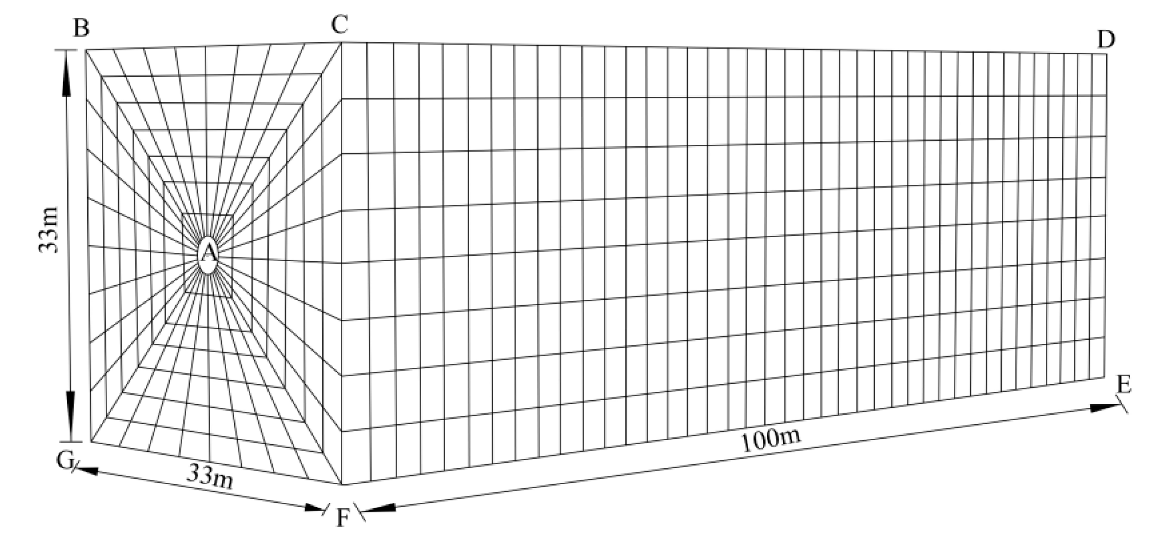
4.1. Model Establishment

Based on the geological engineering conditions of a hydraulic tunnel in Xinjiang, a numerical calculation model was established using the finite element software ABAQUS. According to the analytical theory, in order to reduce the influence of boundary effects, the boundary range of five times the diameter of the circular tunnel was usually used for the study of stress problems [25]. Therefore, the calculation range of wall rock was selected as 33 m × 33 m × 100 m, and the model meshing diagram is shown in Figure 4. In order to facilitate the model establishment, this paper took the horizontal plane direction as the x-axis, the tunnel axis direction as the y-axis, and the upward direction vertical to the x-y plane as the z-axis. According to the geological engineering data of this tunnel, the corresponding mechanical parameters were assigned to the wall rock. Taking the stability of the rock mass under the condition of low-temperature freezing in the simulated tunnel into account, normal constraints were applied to the boundary of the x direction and y direction, and the bottom of the model was set to the full constraint.
In the form of equivalent load, the overlying strata of the model tunnel was applied to the upper boundary of the model, and the vertical pressure of the upper boundary of the model was taken as 4.12 MPa. The pore water was developed in the entrance section of the tunnel. Therefore, the model assumed the rock mass was in a water-saturated state. According to the constant water head boundary of the entrance section of the project, the pore water pressure of the tunnel wall rock was calculated. The calculation results showed that the pore water pressure of 0.49 MPa should be applied to the upper boundary and 0.81 MPa to the lower boundary. Because the wall rock at the tunnel entrance section in cold regions were not only affected by the convective heat transfer of the cold temperature in the tunnel cavity but also by the convection and heat conduction of the ambient temperature on the free face of the entrance, the convective heat transfer boundary was adopted for the model cavity and the free face of the entrance. The convective heat transfer coefficient was 39.96 W/(m2·°C). The ambient temperature was the on-site measured value. The temperature boundary of the rock mass around the model was the stable thermal boundary [26], and the temperature was 20 °C, which was the ground temperature of the rock mass at the burial depth. The initial temperature inside the rock mass was the temperature gradient from 5 to 20 °C.

4.2. Determination of Parameters

Based on the geological survey, design and experimental data of the hydraulic tunnel, this paper used the engineering analogy method to comprehensively select values. The required parameters of the wall rock are shown in Table 2.

4.3. Subsection

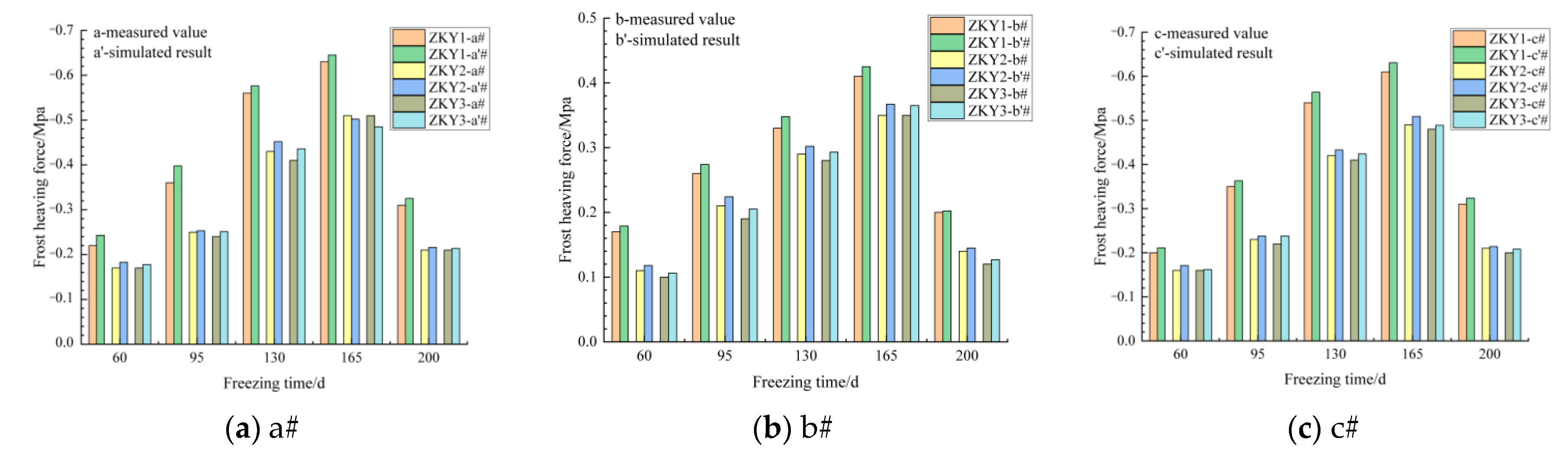
4.3.1. Verification of Calculation Results

In order to verify the accuracy of the numerical calculation results, the monitoring values of the freezing depth and frost heaving force of the section at different freezing time nodes were compared with the simulated values of the finite element calculation results, as shown in Figure 5 and Figure 6.
From Figure 5, the freezing depth of the rock mass first increased and then decreased with the freezing temperature, but the maximum freezing depth was observed after the maximum negative temperature, which was due to the hysteresis of heat conduction. The simulation values of the freezing depth were mostly greater than the monitoring values. The maximum error of the freezing depth between the monitoring data and simulation result was 0.26 m. The certain error between the monitoring values and the simulation results was due to the fact that the actual joint structure inside the wall rock was not considered, and the thermal conductivity was affected by the existence of structural planes.
From the analysis of Figure 6, it can be obtained that the overall variation law of frost heaving force was similar to that of the freezing depth. The maximum errors of frost heaving force between the monitoring data and simulated results at the arch top, arch waist and arch bottom were 0.038 MPa, 0.017 MPa and 0.024 MPa respectively. The overall error was within 8%.
Therefore, it can be concluded that the numerical calculation results are in good agreement with the measured values, and the model has better reliability and is feasible to analyze the frost heaving characteristics of wall rock.

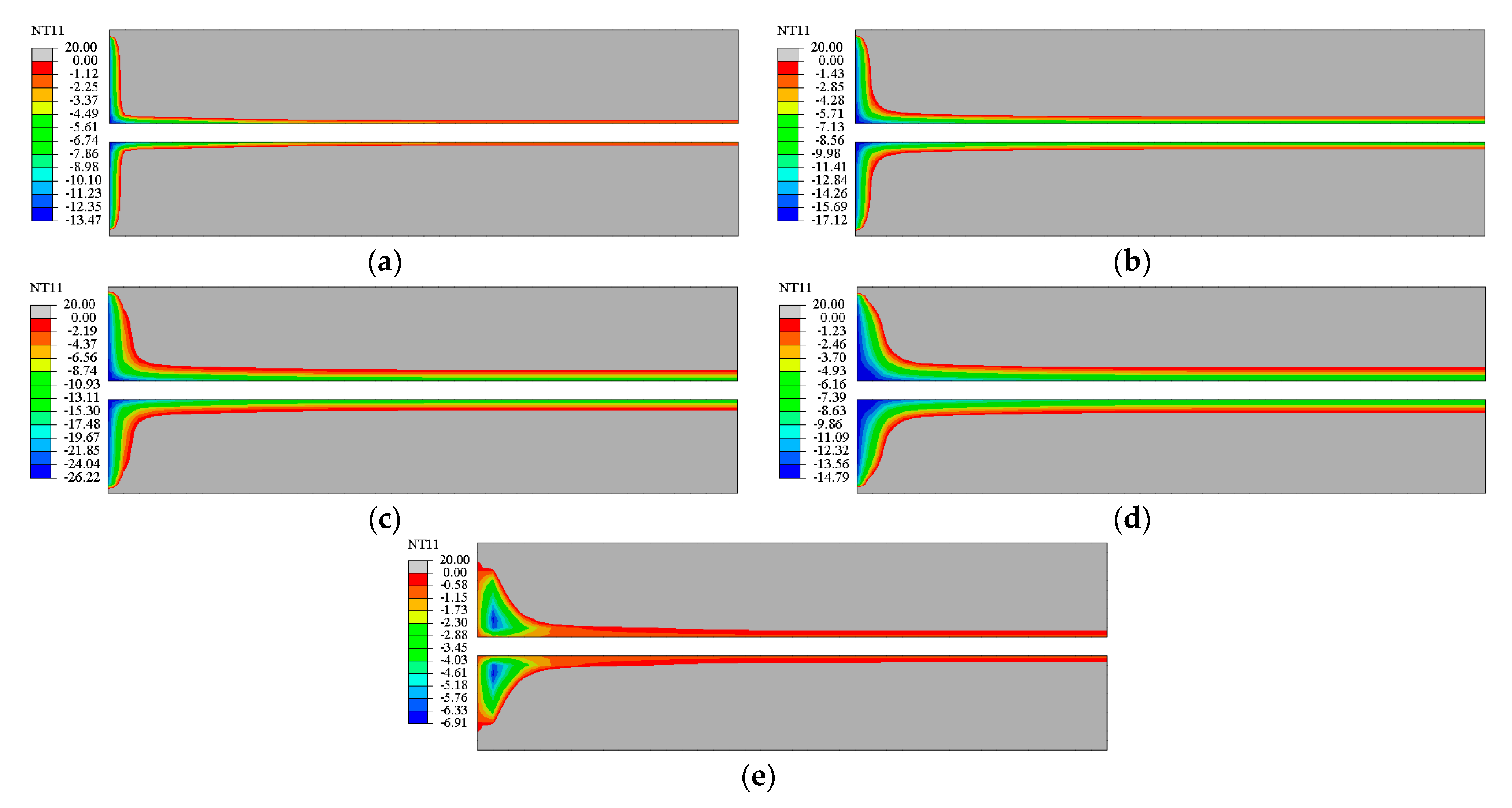
4.3.2. Analysis of the Spatial Distribution and Variation Law of the Frozen Area

In order to analyze the spatial distribution and variation law of the frozen area of hydraulic tunnels in cold regions, the vertical distribution cloud map of the frozen area in wall rock on day 60, 95, 130, 165 and 200 was taken, as shown in Figure 7. From Figure 7, it can be seen that the temperature field of the tunnel’s wall rock was significantly affected by the low-temperature environment of the tunnel cavity and the free face. The pore water in the wall rock underwent phase transition due to freezing. The frozen area of the wall rock was in the shape of a long-necked funnel. During the freezing and cooling period from day 60 to 130, the freezing depth of wall rock changed greatly. The freezing front moved toward the interior of the wall rock, the freezing circle of section increased, and the spatial region of the entire frozen area gradually increased. During the freezing and warming period from day 130 to 200, the freezing depth of wall rock first increased and then decreased, which was due to the continuous effect of low negative temperature and the hysteresis of heat conduction in the surrounding rocks. After the maximum negative temperature appeared, the freezing depth of the wall rock gradually increased, and the frozen area enlarged. However, as the ambient temperature gradually increased, due to the effect of ground temperature, the wall rock at the maximum freezing depth gradually thawed, the freezing depth decreased, and the frozen area shrank. This is consistent with the monitoring results of Li Yanming [27] in the Huitougou tunnel.

4.3.3. Analysis of the Spatial Distribution and Variation Law of the Frost Heaving Force

Figure 8 shows the circumferential distribution curve of the frost heaving force over time calculated by finite element method. It can be concluded from Figure 8 that the circumferential distribution of wall rock frost heaving force at three cross sections, ZKY1, ZKY2 and ZKY3, obtained by the simulation is the frost heaving tension generated at the arch top reduced to zero along the circumferential direction, and then turned into the frost heaving pressure which reached the maximum at the arch waist. Then, the frost heaving pressure was reduced to zero and turned into the frost heaving tension, which increased till the arch bottom. Accordingly, the circumferential distribution of frost heaving force of the wall rock remained consistent along the depth. The frost heaving forces of wall rock are symmetrical vertically and horizontally.
Variation of finite element calculation values of frost heaving force at arch top, arch waist and arch bottom over time and depth are shown in Figure 9, where positive frost heaving force represents compressive stress and negative frost heaving force represents tensile stress. By analyzing Figure 9, it can be seen that:
(1)
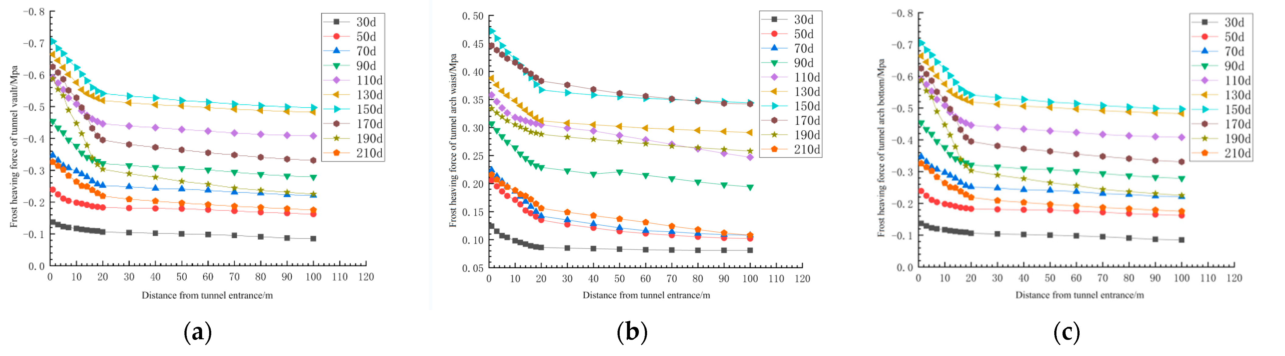
In different time periods, the maximum absolute values of wall rock frost heaving force were on cross sections. With the increase of depth, the absolute values of wall rock frost heaving force were decreasing. The frost heaving force of the wall rock was divided into a steep decline zone and a slow decline zone at the distance of 20 m away from the tunnel entrance. In the first 20 m range of the entrance, the absolute value of frost heaving force changed rapidly with the increase of depth. In the 20 m~100 m range of the entrance, the absolute values of frost heaving force slowly decreased with the increase of depth.
(2)
The absolute value of frost heaving force at the arch top, arch waist and arch bottom had an increasing trend from day 30 to 150 and had a decreasing trend from day 150 to 210. During day 30 to 150, the absolute value of maximum frost heaving force at arch top increased from 0.137 MPa to 0.705 MPa, with a growth rate of 414.6% and the absolute value of maximum frost heaving force at arch waist increased from 0.124 MPa to 0.471 MPa, with a growth rate of 279.8%. During day 150 to 210, the absolute value of maximum frost heaving force at arch top decreased from 0.705 MPa to 0.325 MPa, with a decreasing rate of 53.9% and the absolute value of maximum frost heaving force at arch waist decreased from 0.471 MPa to 0.215 MPa, with a growth rate of 54.4%. In the whole process, the value and variation trend of frost heaving force at arch top and arch bottom was basically the same. The growth rate of the maximum frost heaving force at the arch top and arch bottom was about 1.5 times that of the arch waist. Therefore, the arch top and arch bottom are affected more significantly by the frost heaving force.
(3)
The frost heaving forces at the arch waist were basically the same on day 170 and 150, which were significantly greater than that on day 130 in the same place. However, the frost heaving forces of day 170 at all locations were closer to the frost heaving forces on day 130 at the same places, and significantly greater than the frost heaving forces on day 170 at the same places. This means the value of the frost heaving force at the arch top entered the decline period earlier than that at the arch waist.
The failure mechanism of hydraulic tunnel in cold regions under frost heaving force is shown in Figure 10. The schematic diagram of the damaged hydraulic tunnel in cold regions under frost heaving force is shown in Figure 11.
Under the continuous action of low temperature, the water in the wall rock froze. As the freezing duration increased, the temperature field of the wall rock changed continuously, and water migration and freezing gradually occurred inside the wall rock. Due to the effect of cavity, free face and ground temperature, the region of the temperature field near the tunnel entrance that reached the freezing temperature became larger. Therefore, the wall rock near the entrance of hydraulic tunnel in cold regions produced more cracks and the structure at the entrance was subject to greater frost heaving tension and frost heaving pressure, resulting in greater transverse deformation at the entrance of hydraulic tunnel in cold regions than at other positions. This is one of the important reasons why frost heaving damage often occurs in the entrance section of hydraulic tunnels in cold regions.

5. Conclusions

Based on thermodynamics, fluid mechanics, continuum mechanics, segregation potential theory and Tazaghi’s Principle, with the consideration of low-temperature water-ice phase transition temperature field, seepage field and stress field, a coupling governing equation is derived. Based on the derived coupling governing equation and combining with an engineering example, finite element analysis software was used to establish three-dimensional model of frost heave and numerical analysis was carried out on the frost heave properties, The following conclusions can be drawn:
(1)
The model verification showed that the maximum error of freezing depth between the monitoring values and the simulation results was 0.26 m, and the error of the frost heaving force between the monitored and simulated results at the arch top, arch waist and arch bottom was within 8%. Therefore, it can be concluded that the numerical calculation results of three-dimensional finite element based on the derived coupling governing equation are in good agreement with the measured values, and the model has better reliability.
(2)
During the freezing period of the hydraulic tunnel in cold regions, the frozen area of the hydraulic tunnel was spatially distributed in a long-necked funnel shape. Due to the effect of ground temperature as well as convection and heat conduction of the free face and tunnel cavity, the frozen area in wall rock increased first and then decreased during the entire freezing period. Due to the hysteresis of heat conduction, the peak of the maximum freezing depth appeared after the minimum value of the ambient temperature.
(3)
The circumferential distribution law of frost heaving force in wall rock remained consistent. Comparing the variation of circumferential stress distribution of three cross sections, ZKY1, ZKY2 and ZKY3, on five freezing time points, we can find that the wall rock frost heaving forces are symmetrical vertically and horizontally, the maximum frost heaving force is at the arch top and arch bottom and the maximum frost heaving pressure is at arch top.
(4)
Taking 20 m away from the tunnel entrance as the boundary, the frost heaving force at the arch top and arch waist of wall rock can be divided into a steep decline zone and a slow decline zone. The maximum frost heaving force of the wall rock was at the entrance section. The absolute value of frost heaving force of the arch top, arch waist and arch bottom at the entrance section had an increasing trend from day 30 to 150, and a decreasing trend from day 150 to 210. However, the growth rate of maximum frost heaving force at the arch and bottom is about 1.5 times that at the arch waist, indicating that the influence of frost heaving on the arch top and arch bottom was greater than that on the arch waist. Thus, the arch top and arch bottom are affected more significantly by the frost heaving force.

Author Contributions

Methodology, guidance, review and revision, H.J.; data curation and software, D.Z.; analysis, translation, editing and review, P.X.; supervision and interpretation of data, G.W. All authors have read and agreed to the published version of the manuscript.

Funding

This research was supported by the National Natural Science Foundation of China, Grant number 51769031; and the Regional innovation Guidance Plan project of the XPCC, Grant number 2021BB004.

Institutional Review Board Statement

Not applicable.

Informed Consent Statement

Not applicable.

Data Availability Statement

Not applicable.

Conflicts of Interest

The authors declare no conflict of interest.

References

  1. Ma, W.; Wang, D.Y. Studies on frozen soil mechanics in China in past 50 years and their prospect. Chin. J. Geotech. Eng. 2012, 34, 625–640. [Google Scholar]
  2. Zhang, M.Y.; Pei, W.S.; Li, S.Y.; Lu, J.G.; Jin, L. Experimental and numerical analyses of the thermal-mechanical stability of an embankment with shady and sunny slopes in permafrost regions. Appl. Therm. Eng. 2017, 127, 1478–1487. [Google Scholar]
  3. Liu, S.H. Lessons of hydraulic tunnel accident. Water Resour. Hydropower Eng. 2000, 31, 38–40. [Google Scholar]
  4. Zhang, Y.X. Study on Frost Resistance, Anti-Freezing and Drainage Technology of the Galongla Tunnel. Master’s Thesis, Chongqing Jiaotong University, Chongqing, China, 2009. [Google Scholar]
  5. Brovka, G.P.; Ivanov, S.N. Calculation of temperature fields in the ground with water-ice phase transitions in the temperature spectrum. J. Eng. Phys. Thermophys. 2004, 77, 1192–1200. [Google Scholar]
  6. Tan, X.J.; Chen, W.Z.; Jia, S.P.; Lv, S.P. A coupled hydro-thermal model for low temperature rock including phase change. Chin. J. Rock Mech. Eng. 2008, 27, 1455–1461. [Google Scholar]
  7. Tan, X.J.; Chen, W.Z.; Tian, H.M.; Cao, J.J. Water flow and heat transport including ice-water phase change in porous media:Numerical simulation and application. Cold Reg. Sci. Technol. 2011, 68, 74–84. [Google Scholar]
  8. Zhang, X.D.; Wu, Y.J.; Zhai, E.C.; Ye, P. Coupling analysis of the heat-water dynamics and frozen depth in a seasonally frozen zone. J. Hydrol. 2020, 593, 125603. [Google Scholar]
  9. Bekele, Y.W.; Kyokawa, H.; Kvarving, A.M.; Kvamsdal, T.; Nordal, S. Isogeometric analysis of THM coupled processes in ground freezing. Comput. Geotech. 2017, 88, 129–145. [Google Scholar]
  10. Li, G.F.; Li, N.; Bai, Y.; Liu, N.F.; He, M.M.; Yang, M. A novel simple practical thermal-hydraulic-mechanical (THM) coupling model with water-ice phase change. Comput. Geotech. 2020, 118, 103357. [Google Scholar]
  11. Huang, S.B.; Liu, Q.S.; Cheng, A.P.; Liu, Y.Z.; Liu, G.F. A fully coupled thermo-hydro-mechanical model including the determination of coupling parameters for freezing rock. Int. J. Rock Mech. Min. Sci. 2018, 103, 205–214. [Google Scholar]
  12. Wu, D.; Zhang, Y.L.; Zhao, R.K.; Deng, T.F.; Zheng, Z.X. A coupled thermal-hydraulic-mechanical application for subway tunnel. Comput. Geotech. 2017, 84, 174–182. [Google Scholar]
  13. Xia, C.C.; Lv, Z.T.; Huang, X.H.; Li, Q. Semi-analytical method of maximum frozen depth calculation in cold region tunnel. Rock Soil Mech. 2018, 39, 2145–2154. [Google Scholar]
  14. Wang, C.H.; Jin, S.L.; Wu, Z.Y.; Cui, Y. Evaluation and application of the estimation methods of frozen (thawing) depth over China. Adv. Earth Sci. 2009, 24, 132–140. [Google Scholar]
  15. Xia, C.C.; Lv, Z.T.; Li, Q.; Huang, J.H.; Bai, X.Y. Transversely isotropic frost heave of saturated rock under unidirectional freezing condition and induced frost heaving force in cold region tunnels. Cold Reg. Sci. Technol. 2018, 152, 48–58. [Google Scholar]
  16. Feng, Q.; Fu, S.G.; Wang, C.X.; Liu, W.W.; Wang, W.; Qiao, W.G. Analytical elasto-plastic solution for frost force of cold-region tunnels considering anisotropic frost heave in the surrounding rock. KSCE J. Civ. Eng. 2019, 23, 3831–3842. [Google Scholar]
  17. Lv, Z.T.; Xia, C.C.; Wang, W.S.; Luo, J. Analytical elasto-plastic solution of frost heaving force in cold region tunnels considering transversely isotropic frost heave of surrounding rock. Cold Reg. Sci. Technol. 2019, 163, 87–97. [Google Scholar]
  18. Lyu, Z.T.; Xia, C.C.; Liu, W.P. Analytical solution of frost heaving force and stress distribution in cold region tunnels under non-axisymmetric stress and transversely isotropic frost heave of surrounding rock. Cold Reg. Sci. Technol. 2020, 178, 103117. [Google Scholar]
  19. Zhu, Y.M.; Li, Y.S.; Hao, Z.H.; Luo, L.; Luo, J.X.; Wang, L. An analytical solution for the frost heaving force and displacement of a noncircular tunnel. Comput. Geotech. 2021, 133, 104022. [Google Scholar]
  20. Meng, Y.; Jiang, H.B. The distribution law of surrounding rock temperature field of a hydraulic tunnel in cold region based on convection-conduction coupling model. J. Water Resour. Water Eng. 2020, 31, 221–226. [Google Scholar]
  21. Bonacina, C.; Comini, G.; Fasano, A.; Primicerio, M. Numerical solution of phase-change problems. Int. J. Heat Mass Transf. 1973, 16, 1825–1832. [Google Scholar]
  22. Konrad, J.M.; Morgenstern, N.R. The segregation potential of a freezing soil. Can. Geotech. J. 1981, 18, 482–491. [Google Scholar]
  23. Shen, Z.J. Theoretical Soil Mechanics, 1st ed.; China Water & Power Press: Beijing, China, 2000; pp. 136–153. [Google Scholar]
  24. Liang, B.; Jiang, H.L.; Sun, W.J.; Jin, J.X. Study on numerical simulation of seepage law for multi-crack rock. J. Water Resour. Water Eng. 2013, 24, 79–81. [Google Scholar]
  25. Zheng, Y.R.; Zhu, H.H.; Fang, Z.C.; Liu, H.H. Stability Analysis and Design Theory of Underground Engineering Surrounding Rock, 1st ed.; China Communications Press: Beijing, China, 2012; pp. 205–213. [Google Scholar]
  26. Mo, Z.G.; Jiang, H.B.; Hou, X.B. Study on transient temperature and stress coupling of surrounding rock of water diversion tunnel with high ground temperature under different excavation methods. Water Power 2019, 45, 58–63. [Google Scholar]
  27. Li, Y.M. Experimental Study on Frost Heaving Force of Surrounding Rock of Huihuigou Tunnel. Master’s Thesis, Jilin University, Changchun, China, 2018. [Google Scholar]
Figure 1. Working condition diagram of underground water tunnel of a hydropower station in Xinjiang.
Buildings 12 01026 g001
Figure 2. Layout of temperature stress measuring points.
Buildings 12 01026 g002
Figure 3. Temperature monitoring curves of each section. (a) Temperature monitoring curves of section ZKY1. (b) Temperature monitoring curves of section ZKY2. (c) Temperature monitoring curves of section ZKY3.
Buildings 12 01026 g003
Figure 4. 3D model meshing diagram.
Buildings 12 01026 g004
Figure 5. Comparison and verification of measured values and finite element simulated values of freezing depth (unit: m).
Buildings 12 01026 g005
Figure 6. Comparison and verification of measured values and finite element simulated values of frost heaving force (unit: MPa).
Buildings 12 01026 g006
Figure 7. Vertical temperature cloud map. (a) 60 d after freezing. (b) 95 d after freezing. (c) 130 d after freezing. (d) 165 d after freezing. (e) 200 d after freezing.
Buildings 12 01026 g007
Figure 8. Variation of circumferential distribution curve of frost heaving force over time (unit: MPa). (a) ZKY1-frost heaving force. (b) ZKY2-frost heaving force. (c) ZKY3-frost heaving force.
Buildings 12 01026 g008
Figure 9. Variation curve of frost heaving force that changes over time and depth. (a) Tunnel vault. (b) Tunnel arch waist. (c) Tunnel arch bottom.
Buildings 12 01026 g009
Figure 10. The failure mechanism of hydraulic tunnels in cold regions under frost heaving force. (a) Initial state of hydraulic tunnel in cold regions. (b) The state of hydraulic tunnel after destruction in cold regions.
Buildings 12 01026 g010
Figure 11. The schematic diagram of damaged hydraulic tunnels in cold regions under frost heaving force.
Buildings 12 01026 g011
Table 1. Monitoring values of frost heaving force at different time nodes (unit: MPa).
Time NodeZKY1ZKY2ZKY3
ZKY1-a#ZKY1-b#ZKY1-c#ZKY2-a#ZKY2-b#ZKY2-c#ZKY3-a#ZKY3-b#ZKY3-c#
60 d−0.220.17−0.20−0.170.11−0.16−0.170.10−0.16
95 d−0.360.26−0.35−0.250.21−0.23−0.240.19−0.22
130 d−0.560.33−0.54−0.430.29−0.42−0.410.28−0.41
165 d−0.630.41−0.61−0.510.35−0.49−0.510.35−0.48
200 d−0.310.20−0.31−0.210.14−0.21−0.210.12−0.20
Table 2. Parameters of wall rock.
MaterialsDensity
ρ/(kg/m3)
Elastic Modulus
E/GPa
Poisson Ratio
μ
Cohesion
c/MPa
Internal Friction Angle
φ/(°)
Thermal Conductivity
λ/(w/(m·°C))
Specific Heat Capacity C/(J/(kg·°C)Porosity
n
Permeability Coefficient
k/(m/s)
Frozen surrounding rocks21304.10.270.41373.1712600.276.8 × 10−6
Unfrozen surrounding rocks21303.20.300.47302.2515340.272.4 × 10−5
Publisher’s Note: MDPI stays neutral with regard to jurisdictional claims in published maps and institutional affiliations.

