Article

Analytical Procedure for Timber−Concrete Composite (TCC) System with Mechanical Connectors

1
Department of Civil and Environmental Engineering, University of Illinois at Urbana-Champaign, 205 North Mathews Avenue, Urbana, IL 61801, USA
2
Department of Mechanical Engineering, University of Alberta, 9211 116 Street NW, Edmonton, AB T6G 1H9, Canada
3
Department of Civil and Environmental Engineering, Natural Sciences and Engineering Research Council of Canada Industrial Research Chair in Engineered Wood & Building Systems, University of Alberta, 9211 116 Street NW, Edmonton, AB T6G 1H9, Canada
*
Authors to whom correspondence should be addressed.
Buildings 2022, 12(7), 885; https://doi.org/10.3390/buildings12070885
Submission received: 4 June 2022 / Revised: 18 June 2022 / Accepted: 20 June 2022 / Published: 22 June 2022
(This article belongs to the Section Building Structures)

Abstract

:
In the construction of modern multi-storey mass timber structures, a composite floor system commonly specified by structural engineers is the timber–concrete composite (TCC) system, where a mass timber beam or mass timber panel (MTP) is connected to a concrete slab with mechanical connectors. The design of TCC floor systems has not been addressed in timber design standards due to a lack of suitable analytical models for predicting the serviceability and safety performance of these systems. Moreover, the interlayer connection properties have a large influence on the structural performance of a TCC system. These connection properties are often generated by testing. In this paper, an analytical approach for designing a TCC floor system is proposed that incorporates connection models to predict connection properties from basic connection component properties such as embedment and withdrawal strength/stiffness of the connector, thereby circumventing the need to perform connection tests. The analytical approach leads to the calculation of effective bending stiffness, forces in the connectors, and extreme stresses in concrete and timber of the TCC system, and can be used in design to evaluate allowable floor spans under specific design loads and criteria. An extensive parametric analysis was also conducted following the analytical procedure to investigate the TCC connection and system behaviour. It was observed that the screw spacing and timber thickness remain the most important parameters which significantly influence the TCC system behaviour.

1. Introduction

Global concern about reducing greenhouse gases (GHG) in construction has come to the forefront in the last few decades. Timber construction possibilities have broadened significantly as a result of modifications in building codes, the emergence of innovative engineered wood materials, and mechanical fastening. New generations of innovative engineered wood products such as mass-timber panel (MTP) (e.g., glued-laminated timber, cross-laminated timber, dowel-laminated timber, nail-laminated timber, massive plywood panel, etc.) and structural composite lumber (SCL) (e.g., oriented strand lumber, laminated strand lumber, parallel strand lumber, laminated veneer lumber, etc.) have the structural capabilities to be employed as low-carbon alternatives to steel and concrete in a variety of applications. New innovative connectors (e.g., self-tapping screw, glued-in rod, glued-in plate, shape memory alloy dowels, etc.) allow significantly larger forces than would be possible using traditional fasteners such as bolts and lag screws to be transferred between structural timber members. These developments have led to larger and taller mass timber structures with the added benefits of being lighter and faster in construction due to pre-fabrication [1].
Structural systems using timber alone are often not the most efficient due to the inherent low mechanical properties of timber in comparison with other common structural materials. Innovative hybrid structural systems, whereby timber is combined strategically with other materials so that the attributes of one material can address the weaknesses of the other, often offer more efficient and economical design solutions than timber alone systems. A timber–concrete composite (TCC) is a timber-based hybrid structural system in which a mass timber beam (e.g., glulam) or mass timber panel (MTP) or structural composite lumber (SCL) is connected to a reinforced concrete slab with connectors (e.g., dowel type fasteners, notches, glued-in plates, adhesives, notches with dowel type fasteners) and the possible presence of soft insulation layers or rigid timber planks in between the timber and concrete. A typical longitudinal section of a TCC system with dowels, notches, and glued-in-plates is shown in Figure 1. This system is promoted by designers in the construction of modern multi-storey mass timber buildings due to its higher strength and stiffness to weight ratios, larger span to total depth ratio, and higher in-plane rigidity. In addition to the structural benefits, TCC systems also offer better acoustic, thermal, and fire performance when compared with conventional timber-only systems [2,3,4,5].
The mechanical shear connectors, which penetrate all three components (concrete slab, insulation, and timber), allow for the partial shear transfer and provide partial composite action to the system. The connectors must be strong, stiff, and ductile enough to transfer the design shear force between the brittle timber and concrete components to provide an adequate partial composite action. The structural efficiency of this composite system mostly depends on the performance of this interlayer connection [5,6]. In particular, the stiffness of the interlayer connection has a direct influence on the effective bending stiffness of a TCC system. Serviceability performance requirements, such as deflection and vibration, are often governed by the TCC system’s allowable floor spans, which are directly dependent on effective bending stiffness. The sandwiched insulation layer between the MTP/SCL and the concrete slab is often provided to enhance the acoustic and thermal performance of the TCC system with MTP/SCL. This inter-layer practically serves as a gap and has a negative impact on the strength and stiffness of the connection [7]. Relative slip between the bottom fibre of concrete and the top fibre of lumber occurs as a result of the semi-rigid interlayer mechanical shear connector, which violates the Euler−Bernoulli beam assumption of “plane sections remain plane”. As a result, the transformed section method for determining composite bending stiffness and stress distribution, which is widely used in the design of reinforced concrete beams, cannot be employed in the design of TCC beams. Moreover, in such a partial composite system, the interlayer slip leads to two neutral axes, and the composite action of the system largely depends on the locations of these neutral axes.
Dowel-type fasteners are the most common connection type used for TCC systems for their ductile behaviour. The common dowel-type fastener used in modern mass timber, including composite floor systems, is self-tapping screws (STS) [8]. Several other mechanical connectors also exist, such as nails, bolts, dowels, wood screws, coach/lag screws, and Tecnaria shear stud connectors with crampons, which can also be used in the TCC joint [3,5,9]. Fully threaded screws with a wide countersunk head are effective in the application of timber concrete composites because the full thread provides better load transfer in the timber and better bonding with the concrete, while the countersunk head gives pullout resistance in concrete [7]. Besides, several screws were specifically developed for application in timber–concrete composite systems with cylindrical countersunk heads [10] or hexagonal heads [11]. There have been several experimental and theoretical studies of STS connections in timber-to-timber [12,13,14,15,16,17,18], steel-to-timber [17,19,20,21], and concrete-to-timber [22,23,24,25] systems, which have concluded that installing the screw at an angle (e.g., 45° or 30°) to the surface of the timber member increases the strength and stiffness significantly. For concrete-to-timber STS connections, it was experimentally [7], and later analytically [26,27], proven that there is a significant increase in strength and stiffness of the connection when the screws are inserted at a 30° angle to the timber member surface compared to a 45° angle.
The load transfer mechanism in joints with inclined fasteners is complicated because it involves not only the bending of the fasteners and the embedding of the wood, but also the resistance of the fasteners to being pulled out, as well as friction between the different parts. Eurocode 5 [28] introduced interaction equations for calculating the strength and stiffness of fasteners under bi-directional loading, which are not applicable to the fasteners at an inclined position due to the lack of consideration of contribution from the withdrawal action. Because there is currently no method for evaluating inclined connector properties, tests are frequently conducted using standardized procedures such as EN 26891:1991 to characterize the strength and stiffness of the connectors [29]. To circumvent the requirement for testing, analytical models for predicting connection strength [26] and stiffness [27] have been developed for dowel-type connectors inserted at any angle to the face of the member. Inputs into these models are the component properties such as embedment and withdrawal strength and stiffness of the connector in wood, bending yield moment and stiffness of the connector, and friction coefficient at the timber–concrete interface. The connection models were validated with a wide range of connection test data [7] and were found to predict the connection capacity and stiffness within 10% and 18% of the experimental values [26,27].
Analytical modelling offers a convenient approach to study the structural performance of TCC systems [30,31,32,33] that requires little computational effort and can be readily adopted for design use. Apart from the Gamma method [2] in Eurocode 5 [28], timber design standards around the globe do not address the design of TCC systems. Based on the assumption of sinusoidal distributed load and smeared connection between concrete and timber, the close-form solution of the Gamma method, which is commonly used in engineering design, was obtained. It has been found to be a practical method that provides reasonably accurate predictions of elastic bending stiffness for systems that deviate from these assumptions, e.g., closely spaced connectors under a uniformly distributed load [9]. General analytical models, based on the application of virtual work theory, have been developed for predicting load-carrying capacity [34] and effective bending stiffness [35] of TCC floor systems before the onset of concrete cracking. These analytical models were validated with four-point bending test results and were found to predict the bending stiffness and capacity within 10% and 17% of the experimental values [34,35].
Several researchers [5,36] have stated that the cracking of concrete should be accounted for in the design of TCC, as it negatively impacts load-carrying capacity and bending stiffness. Besides, deflection of the TCC system increases over time in the long-term due to the creep, mechano-sorptive creep, and shrinkage of all the components, which can affect the stresses and therefore capacity of the components significantly [5,9,37,38]. To facilitate the practical application of the TCC system, this rheological behaviour also needs to be considered in the simplest way possible. In this study, an analytical procedure is presented based on a progressive yielding mechanism for analyzing TCC with mechanical connectors by incorporating the connection and component properties to predict the load that corresponds to the first failure of any of the components and the effective bending stiffness by improving the models developed by Mirdad and his co-workers [34,35]. The analytical procedure consists of a connection model and a system model. The utilization of the connection model generates the connection behaviour properties that are required by the TCC system model. In the TCC system model, concrete cracking and long-term behaviour of the composite system are accounted for by introducing reduction factors. Using the proposed analytical procedure, engineers can analyze a TCC floor system based on basic material properties without the need to have specific timber–concrete connection properties. Finally, a parametric study was conducted with all possible influencing component parameters by incorporating the connection and system models to investigate the general behaviour of the TCC system with mechanical connectors.

2. Review of the TCC System and Connection Models

The TCC system can be analyzed using the progressive yielding method, as illustrated in Figure 2. Initially, connection properties such as strength and stiffness with a fastener inserted at an angle to the face of the member are required to be predicted from the connection model based on material property parameters, such as timber embedment strength/stiffness and the withdrawal strength/stiffness of fastener and friction in the timber–concrete interface. Then, the system model can predict the TCC system’s load-carrying capacity, effective bending stiffness, component resistance, and other serviceability requirements based on the input parameters from the connection models and the mechanical properties of the components.

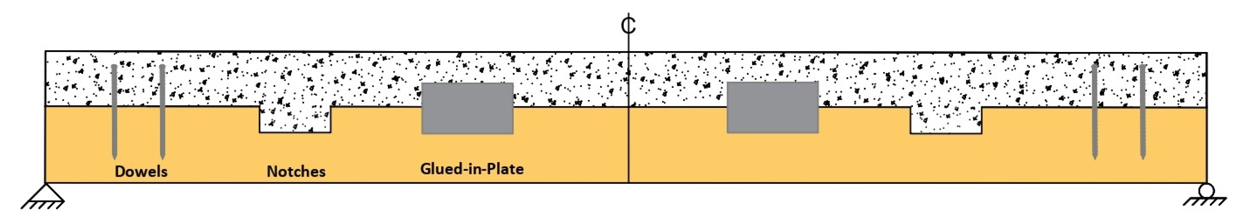
2.1. TCC System Model

The TCC system is shown in Figure 3 with a longitudinal section and a cross-section with mass timber beam and mass timber panel/structural composite lumber. The primary geometric and material parameters are defined as follows: h—depth (mm), A—cross-sectional area (mm2), I—the moment of inertia (mm4), E—modulus of elasticity (MPa), L—span (mm), and b—width of the cross-section (mm) of concrete slab, insulation, timber, and TCC with the subscripts c, i, t, and TCC, respectively.
The structural system of the TCC can be defined by the following conditions:
  • The beam is simply supported in one-way action under a uniformly distributed load.
  • The cross-section consists of mass timber beams or mass timber panels at the bottom and a concrete slab at the top, with the possible presence of insulation layers or planks in between the timber and the concrete slab.
  • The concrete and timber exhibit linear-elastic behaviour and remain in contact at all points along the beam with the shear connectors.
  • The horizontal load transfer between timber and concrete is entirely performed by the linear-elastic perfectly plastic mechanical fasteners which are arranged symmetrically from the mid-span.
An analytical model was developed [34,35] based on superposition and compatibility conditions to determine the redundant shear forces in the connectors of the composite system and therefore the effective bending stiffness. According to the superposition method, the simply supported TCC panel was subdivided into two fictitious sub-systems under a uniform load as shown in Figure 4. In sub-system 1, the fully non-composite system, after releasing the connectors, is analyzed under a uniformly applied load. In sub-system 2, the connectors are replaced by a redundant shear force that acts opposite to the slip caused by the first sub-system. The unknown shear force (Xz) in the interface between concrete and timber is found by applying compatibility conditions when the two sub-systems are combined. In Figure 4, a uniform load w is applied over the span L and the distance between the connectors is nz. Based on the superposition and compatibility conditions, the unknown shear forces (Xz) in r pairs of shear connectors arranged symmetrically about the mid-span can be calculated based on the slips in sub-system 1 and sub-system 2. This is to note that the slip in sub-system 1 is due to the pure bending at the location of the connector between timber and concrete under uniformly distributed load. On the other hand, the slip in sub-system 2 is the relative slip at the connector location for the redundant force, which acts opposite to the slip of sub-system 1. Here, the outermost connector pair can be referred to as index (z) 1, and the index will increase with the decrease in the connector distance from the mid-span. Similarly, the vertical deflection of TCC at mid-span (Δ) due to the applied load can be calculated using the superposition method based on the deflection of sub-systems 1 (Δs1) and 2 (Δs2).

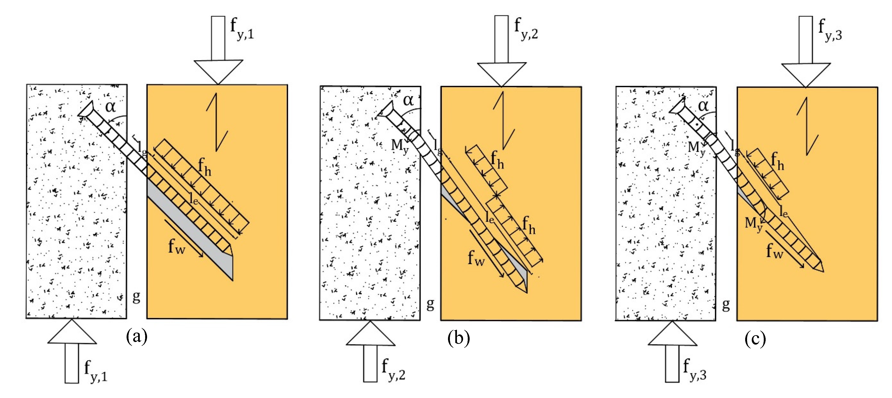
2.2. TCC Connection Model

The structural proficiency of the TCC system primarily depends on the interlayer connection properties. Therefore, mechanics-based analytical models were developed for directly calculating the strength [26] and stiffness [27] of any mechanical connectors in concrete-to-timber joints based on the basic component properties. In the models, both the dowel-bearing (embedment) and withdrawal action of the fastener were incorporated along with other related factors, such as the bending yield moment capacity of the fastener, flexibility of the fastener, and friction between the members.

2.2.1. Connection Strength

Based on [26], the lateral load-carrying capacity (Fy) of fasteners in a connection due to yielding in a single shear plane in a timber–concrete joint can be expressed as shown in Equation (1):
F y = f y n f = m i n f y , 1 ,   f y , 2 ,   f y , 3 n f                        
where nf is the number of fasteners in the joint (two for cross-pair orientation) and fy is the unit lateral yielding resistance per shear plane, (N). fy,1, fy,2, and fy,3 are the unit lateral yield resistance (N) for failure Mode-1, Mode-2, and Mode-3, respectively.
The unit lateral yield resistance, fy, of a concrete-to-timber connection shall be taken as the smallest value calculated in accordance with Equations (2)–(4) based on the stress distributions of three possible failure modes as shown in Figure 5.
f y , 1 = f w π d l e   cos α + μ sin α + f h d l e sin α μ cos α        
f y , 2 = f w π d l e   cos α + μ sin α + f h d sin α μ cos α 2 2 M y f h d + l g 2 + l e + l g 2 2 l g l e  
f y , 3 = f w π d l e   cos α + μ sin α + f h d sin α μ cos α 4 M y f h d + l g 2   l g
where α is the insertion angle to timber grain (degree), d is the nominal diameter of the fastener (mm), M y = 90 d 2.6 is the bending yield moment of the fastener (Nmm),   l e is the fastener penetration into wood excluding the tip (mm), l g = g s i n α is the fastener length in the gap (mm), g is the gap thickness (mm), and μ is the friction in the concrete−timber interface (when there is no insulation gap).
f h   is the embedment strength of timber at a specified insertion angle (N/mm2). Based on [21], the embedment strength of timber at a specified angle can be calculated using Equation (5):
f h = 0.022 ρ 1.24 d 0.3 2.5 cos 2 α + sin 2 α
where ρ is the density of the wood (kg/m3), α is the insertion angle to timber grain (degree), and d is the nominal diameter of the fastener (mm).
f w   is the withdrawal resistance of the fastener at a specified insertion angle (N/mm2). Based on [21], the withdrawal resistance of the fastener per surface at a specified angle can be calculated using Equation (6):
f w = 0.6 d 0.5 l e 0.1 ρ 0.8 π 1.2 cos 2 α + sin 2 α
where l e is the fastener penetration into wood excluding the tip (mm). For CLT, the average value of embedment and withdrawal strengths of all penetrated layers shall be considered as the embedment and withdrawal strength of the product.

2.2.2. Connection Stiffness

Based on [27], the slip modulus for serviceability limit states k (N/mm), of the fasteners in a single shear plane connection in the timber–concrete joint, can be calculated using Equation (7):
k = 3 E I d n f 2 3 l g + 2 l e K w π φ l e cos 2 α + 0.5 μ sin 2 α + 0.9 K h l e 2 sin 2 α 0.5 μ sin 2 α 6 E I 3 l g + 2 l e + 0.9 K h d l e 2 l g 3 sin 2 α
where α is the insertion angle to timber grain (degree), d is the nominal diameter of the fastener (mm), E I is the effective bending stiffness of the fastener (Nmm2), l e is the fastener penetration into wood excluding the tip (mm), l g = g sin α is the fastener length in the gap (mm), g is the gap thickness (mm), nf is the number of fasteners in the joint (2 for cross-pair orientation), φ = K h K w is the stiffness ratio, and μ is the friction in the concrete−timber interface (when there is no insulation gap).
Based on [39], K h is the embedment stiffness of timber at a specified insertion angle (N/mm3) which can be calculated using Equation (8):
K h = 3.781 10 5 ρ 2.443     d 0.956 2.897 cos 2 α + sin 2 α
where ρ is the density of the wood (kg/m3), d is the nominal diameter of the fastener (mm), and α is the insertion angle to the timber grain (degree).
Based on [39], K w is the withdrawal stiffness of the fastener at a specified insertion angle (N/mm3) which can be calculated using Equation (9):
K w = 0.027 l e 0.414     ρ 0.715     d 0.512 0.802 cos 2 α + sin 2 α
where l e is the fastener penetration into wood excluding the tip (mm).
For CLT, the average value of the embedment and withdrawal stiffnesses of all penetrated layers is taken as the product’s embedment and withdrawal stiffness. The mean slip modulus for ultimate limit states (ku) can be assumed to be two-thirds of the slip modulus for serviceability limit states [28].

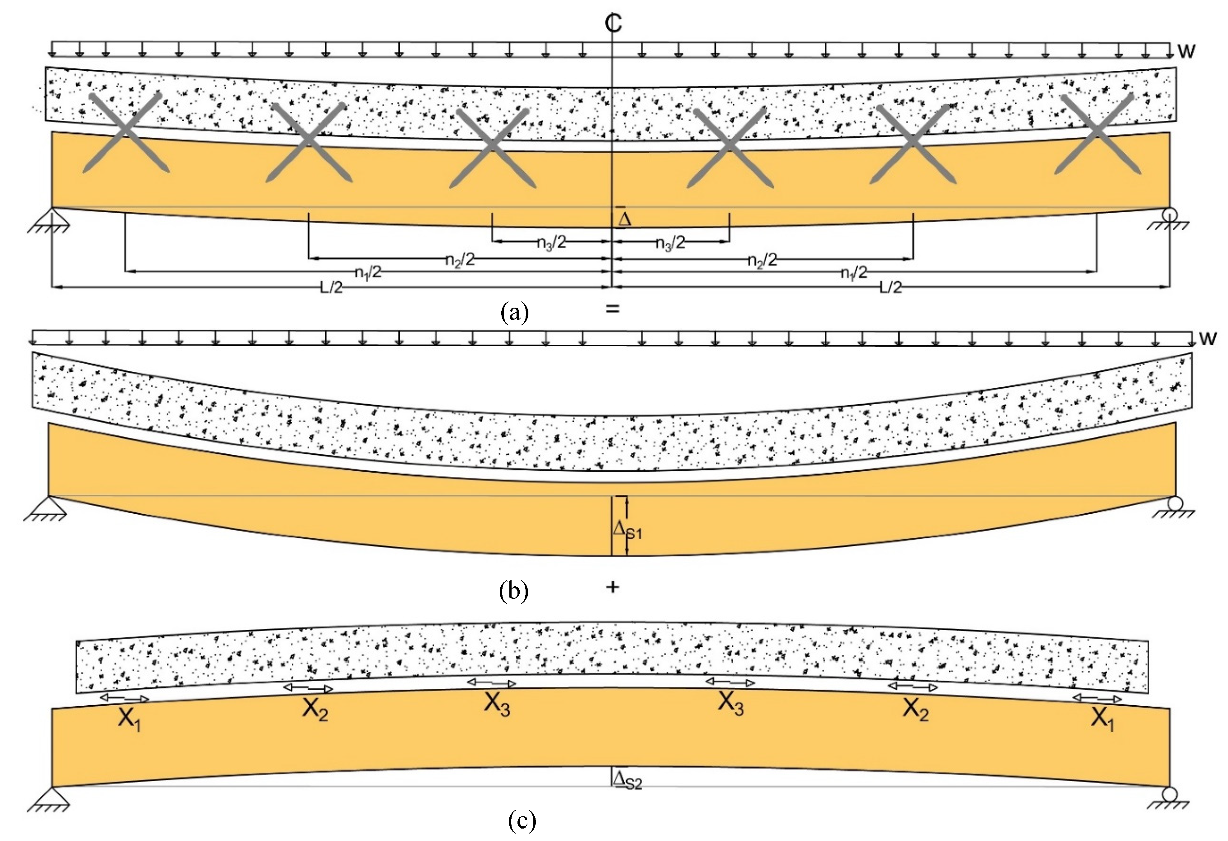
3. Analytical Procedure for Single-Span Simply Supported TCC Beam

The sum of shear forces in all the connectors between the mid-span and the panel edge (Xr) is equal to the resultant normal force at a given cross-section under uniformly distributed load wz. Xr for a given load can be calculated from the following closed-form solutions without solving the matrix as stated in [34]. This summation of the shear forces from all the connectors under applied load (Xr) will be required to calculate the stresses in the components of TCC along with their capacity, besides the deflection calculations of the TCC system.
X r = z = 1 r X z   =   r w z h T C C 3 L 2 n 1 n 1 3 120 E c I c + E t I t ( E c A c + E t A t ) 2 E c A c E t A t + h T C C 2 h i 2 8 E c I c + E t I t z = 1 r n z + 1 k      
where k is the stiffness of the shear connector (N/mm) obtained from testing or an analytical model (e.g., Equation (7)), r is the number of connector rows from midspan, n z is the distance of the connectors from midspan (mm), and n 1 is the distance of the first connector from midspan (mm). The geometric and material properties are mentioned earlier in the analytical model.

3.1. Stresses in Concrete and Timber

The stresses in concrete and timber under the applied load should be checked to determine if either of them fails (e.g., concrete compression, timber tension and/or shear) before the first outermost connectors yield. This approach will allow designers to determine if the first failure is yielding of the connectors, or a material failure in concrete or in timber. As illustrated in Figure 6 and Figure 7, the total stress at each position in a cross-section can be calculated by summing the axial stress from sub-system 1 due to bending and the axial stress from sub-system 2 due to the normal force and bending.
According to the equilibrium condition, the resultant normal force applied to the timber and concrete at a given cross-section is equal to the sum of shear forces in all the connectors between the mid-span and support. Therefore, the axial stresses in the members are
σ t , N = X r A t                     &                       σ c , N = X r A c                  
where X r is the sum of shear forces in all the connectors between the mid-span and panel edge based on Equation (10) and support, σt,N and σc,N are the axial stresses, and At and Ac are the cross-sectional areas of timber and concrete, respectively.
The resultant axial stress due to bending at a position in the cross-section is the sum of the bending stresses obtained from the two sub-systems as shown in Equations (12) and (13):
σ t , B = σ 1 , t + σ 2 , t = 3 E t I t [ 0.25 w z L 2 n z 2 + X r h T C C + h i b t h t 2 E c I c + E t I t      
σ c , B = σ 1 , c + σ 2 , c = 3 E c I c [ 0.25 w z L 2 n z 2 + X r h T C C + h i b c h c 2 E c I c + E t I t      
where σ1,t and σ1,c are the stresses of the member in sub-system 1, σ2,t and σ2,c are the stresses of the member in sub-system 2 due to bending, and σt,B and σc,B are the resultant stresses for timber and concrete, respectively. In sub-system 1, the axial stress in the members is caused by the bending moment assuming the concrete and timber are unconnected, while in sub-system 2, it is caused by the bending moment induced by the eccentric normal force.
The total axial stress for the member is the sum of the stresses in the sub-systems and can be written as
σ t , z = σ t , N + σ t , B               &                   σ c , z = σ c , N + σ c , B            
where σt,z represents the total tensile stress σt,t at the bottom or total compressive stress σt,c at the top of the timber. The bottom extreme fibre stress of timber (σt,t) must not be greater than its bending or tensile strength. On the other hand, σc,i represents the total tensile stress σc,t or total compressive stress of concrete σc,c. The top extreme fibre stress of concrete in compression (σc,c) must not be greater than its compressive strength, and the bottom extreme fibre stress of concrete in tension (σc,t) must not be greater than its modulus of rupture.
From this stress distribution, the neutral axis of each member can be found, and as the degree of composite action decreases, the neutral axes move further apart from each other and toward the respective member centroid. The released and resultant stress distributions in the TCC system with timber beam and mass timber panel/structural composite lumber are shown in Figure 6 and Figure 7, respectively.
The shear stress is most critical in the timber member and the maximum stress happens at the neutral axis of the timber member where flexural stress is zero. The shear stress of timber can be calculated from Equation (15):
τ t = h t 2 ( σ t , N + σ t , B ) 2 E t V 8 σ t , B 2 E I e f f    
where EIeff is the effective bending stiffness of the beam and V is the shear force in the composite cross-section of interest. The shear stress in timber must not be greater than the shear strength of the timber.

3.2. Effective Bending Stiffness

Under the externally applied load, the connectors near the support will reach their yield strength first due to the higher shear forces [34,35], given that all connectors are of the same type. Once the connectors near the supports yield, the load will be redistributed to the remaining elastic connectors until the next connectors yield. The system will become non-linear after the yielding of this first connector, and the stiffness at this point will be the effective bending stiffness of the system, although the stiffness is linear due to the constant load/deflection slope. Instead of the complicated process shown in [35], the linear-elastic effective bending stiffness of the TCC system can be directly calculated from the closed-form solution in Equation (16):
EI e f f = C L 4 E c I c + E t I t C L 4 0.032 r h T C C h T C C + h i ( 2 L n 1 n 1 2 ) 3 L 2 n 1 n 1 3  
C = E c I c + E t I t ( E c A c + E t A t ) 2 E c A c E t A t + h T C C 2 h i 2 8 E c I c + E t I t z = 1 r n z + 1 k          
The symbols for the equations are described earlier in the analytical model.
A yielded connector does not contribute to resisting a load greater than its yield load, which provides the basis for an incremental method to calculate the shear force in the concrete−timber connection. Therefore, by combining the linear calculation with incremental loading, the non-linear post-yielding load-deflection response can be produced. The application of the incremental method to TCC has been described in [35].

3.3. Deflection

Based on the vertical deflection calculated from the superposition method [35], the deflection for a TCC system under a uniformly distributed load (wz) can be calculated using Equation (18):
Δ = 5 w z L 4 19.2 X r n 1 2 L n z h T C C + h i 384 E c I c + E t I t        
The symbols for the equations are described earlier in the analytical model.

3.4. Connector Capacity

One of the ultimate limit states in design is the attainment of yielding in the connector. Therefore, the effective force of the outer-most connector shall be smaller than the yield capacity of the connector F y (from the connection strength Equation (1)) and can be calculated using Equation (19):
F y , e f f = w z h T C C 3 L 2 n 1 n 1 3   76.8 E c I c + E t I t ( E c A c + E t A t ) 2 E c A c E t A t + h T C C 2 h i 2 8 E c I c + E t I t z = 1 r n z + 1 k        
The symbols for the equations are described earlier in the analytical model.

3.5. Floor Vibration

The vibration performance of the TCC floor should be evaluated to prevent objectionable vibrations. According to Hu et al. [40], the vibration-controlled span of a timber–concrete composite floor with a mass timber panel can be directly calculated using Equation (20):
L 0.329 ( E I e f f 1 m ) 0.264   m L 0.207  
where E I e f f 1 m   is the effective bending stiffness of a 1 m wide strip composite beam (Nm2) and mL is the mass per unit length of a 1-m wide strip composite beam (kg/m).

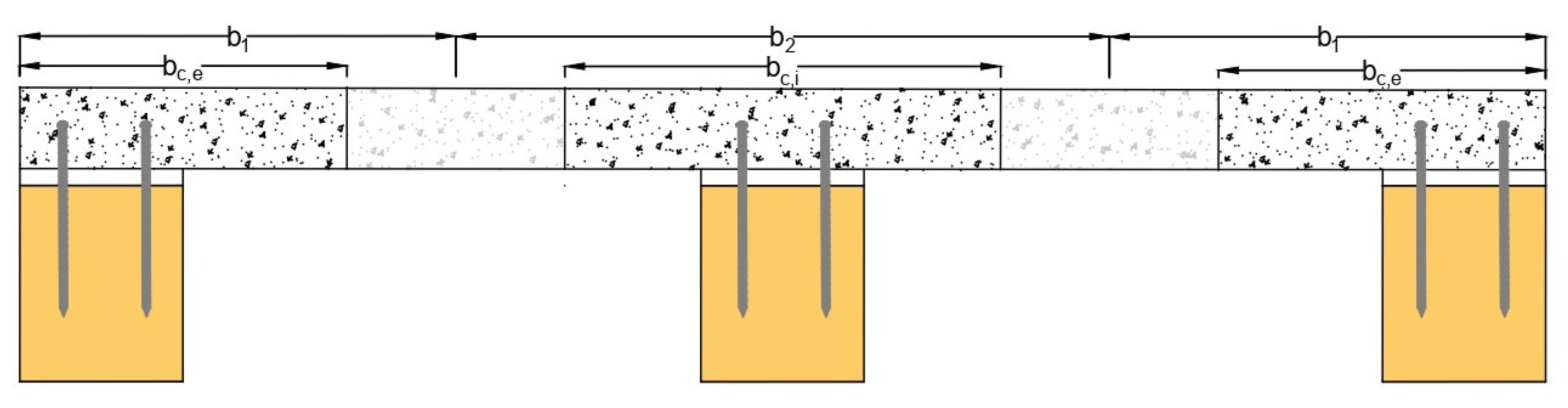
3.6. Component Properties

In the case of TCC with a mass timber panel at the bottom, the effective width of the concrete slab shall be equal to the width of the mass timber panel and needs to be designed for a standard 1 m width. In the case of TCC with a timber beam, the effective width of the concrete slab shall be calculated based on [9] as follows:
b c , e = min 0.1 L ; 12 h c ;   b 1          
b c , i = min 0.25 L ; 24 h c ;   b 2
where bc,e is the effective width of an edge beam (mm), bc,i is the effective width of an internal beam (mm), b1 is the actual concrete width of the edge beam (mm), b2 is the actual concrete width of the middle beam (mm), L is the center-to-center span between the supports (mm), and hc is the thickness of the concrete slab (mm). The effective width of the concrete slab in the TCC with timber beam is illustrated in Figure 8.
After the load is applied, the concrete starts to crack and the neutral axis moves towards the geometric centroid of the cross-section, resulting in a decrease in system bending stiffness and an increase in deflection [1]. The cracking of concrete in the TCC system design is important and should be considered. Cuerrier-Auclair et al. [36] present a moment-curvature method to account for the influence of concrete cracking on the load-carrying capacity of a TCC beam. In that method, to account for the cracks in the concrete slab, a secant method was followed to evaluate the values of the flexural stiffness ( E c I c ), axial stiffness ( E c A c ), and concrete centroid ( d c ) for each increment ( n ). Initially, the axial deformation and the curvature of the concrete slab are calculated at a given n th slip increment. Then the deformation of each j th layer is calculated by assuming the initial centroid. Considering the material laws of concrete and steel ( σ ϵ ), the secant Young’s modulus on each j th layer is determined, followed by calculating the mean secant Young’s modulus for the overall section and then the axial stiffness, E c A c , of the concrete section. Finally, the modified concrete centroid, dc, is then calculated, which later helps in determining the flexural stiffness, E c I c , of the concrete section.
Another method to account for the influence of concrete cracking is given in CSA A23.3 [41]. It provides a simple procedure to consider concrete cracking without reducing the concrete area by excluding concrete in tension. For normal-weight concrete, the steel standard CSA S16-14 [42] neglects the contribution of the tensile resistance of concrete during the calculation of strength and stiffness of steel-concrete composite beams, and a similar approach can be used in timber–concrete composite beam design. According to CSA A23.3-14, the gross moment of inertia (Ig) of concrete is permitted for elastic analysis for ultimate limit state design checks. A multiplying factor as shown in Equation (23) reduces the moment of inertia while the gross section area stays constant. This factor was conservatively enforced by various concrete standards to account for section loss due to concrete cracking. As the TCC system is required to be designed as a strip beam, the gross moment of inertia of concrete needs to be multiplied by the following reduction factor based on [41] to obtain the modified concrete moment of inertia:
I c = 0.35 I g          
The most critical principles for mid-to-large span TCC systems are usually the short and long-term deflections related to the serviceability limit state. In the extended service period of the system, long-term behaviours such as creep, mechano-sorptive creep and shrinkage may occur, which will influence the internal forces and stresses in the components. Shrinkage in concrete induces tensile stress in the concrete slab, yielding increased deformation, which is usually balanced by compression in the timber element under composite action. In the long term, the stress due to shrinkage can be relaxed due to the creep phenomena, which will reduce the deformation due to shrinkage. Besides, shrinkage of timber can decrease tensile forces, yielding decreased deformation of the composite. Accounting for all these phenomena is complex and therefore, to promote this system with more realistic implications, conservative creep adjustment factors can be applied for the effective long-term modulus of each component by neglecting shrinkage. The long-term deflection due to shrinkage of concrete can be reduced by shoring the TCC system before casting the concrete in either the prefabrication or on-site application [43]. According to [9], the specified modulus of elasticity of the concrete, modulus of elasticity of timber, and stiffness of the shear connectors may be multiplied by the following creep adjustment factor for long-term load duration for both serviceability and ultimate limit states as follows:
E c , L T = 0.35 E c  
E t , L T = 0.5 E t          
k L T = 0.25 k
In the case of soft insulation and timber planks, E i I i is small compared with those of concrete and timber and can be ignored in the design. The influence of the gap due to the presence of the insulation or plank on the performance of the connection is already considered in the connection model. The modulus of elasticity, Ec, for different concrete densities can be calculated based on the equation provided by CSA-A23.3-14 [41].

4. Parametric Analysis

An extensive parametric study was carried out using MATLAB software to investigate the influence of different component parameters on the TCC connection and system behaviour. The stated connection and system models were put into the MATLAB code to find the TCC connection’s strength and stiffness, as well as the maximum span that could be used. This was done to meet the structural and serviceability limit state set by the Canadian timber design standard [44]. To investigate the TCC connection behaviour, the parameters are presented in Table 1. Self-tapping screws of different diameters, embedment lengths and insertion angles were considered in the analysis. Initially, the embedment and withdrawal strength of the connection were calculated using Equations (5) and (8) followed by embedment and withdrawal stiffness using Equations (6) and (9). These component properties were then inserted into Equations (1)–(4) and (7) to calculate the connection strength and stiffness, respectively. In this analysis, the friction between timber and the concrete surface was assumed to be zero.
The parameters used to investigate the TCC system behaviour are presented in Table 1. In the floor construction of modern mass timber buildings, TCC with MTP is the most suitable and recommended system due to the large span to total depth ratios. Therefore, a one-meter-width MTP-concrete composite according to Figure 3c was investigated in this study under uniformly distributed loads considering self-weight, a partition wall of 1 kPa, and a live load of 4.8 kPa. Appropriate load combinations were considered according to the National Building Code of Canada (NBCC) [45]. Two cross-pairs of self-tapping screws (four screws) in the transverse direction were considered with a wide range of screw spacings. The connection properties of self-tapping screws at different diameters, embedment lengths, and insertion angles from the connection model were incorporated into the system model. Cross Laminated Timber (CLT) and Glued-Laminated Timber (GLT) with different thicknesses and densities were considered along with the normal weight concrete of different thicknesses. In addition, a 5 mm gap was also considered in between timber and concrete for the insulation/plank, to investigate the TCC behaviour in the presence of an insulation gap. Initially, the stresses (bending and shear) in concrete and timber were checked for the applied load on the composite using Equations (11)–(15). According to the Canadian timber standard [44], the bending strength of the CLT and GLT was assumed 28.5 MPa and 11.8 MPa, while the shear strength was assumed to be 0.5 MPa and 1.5 MPa, respectively. The bottom extreme fibre stress and shear stress of timber (GLT/CLT) were then checked against this specified bending and shear strength of timber using the proper resistance factor that is mentioned in the Canadian timber standard [44]. The top extreme fibre stress of concrete in compression was checked against the concrete compressive strength and the bottom extreme fibre stress of concrete in tension (σc,t) against the concrete modulus of rupture according to the Canadian concrete design standard [41]. The effective bending stiffness of the composite was then calculated using Equations (16) and (17). It is noted that the design of TCC floors is often governed by vibration, and therefore, a vibration-controlled span was developed using Equation (20) [40]. However, the deflection of the TCC under the specified load was checked for the deflection limit (span/180) as specified in the Canadian timber standard [44], using Equation (18). The effective force of the outer-most connector was also checked using Equation (19) with the yield capacity of the connector F y that was found from Equation (1). Each developed span was checked for the strength and serviceability limit state by accounting for concrete cracking (Equation (23)) and long-term load duration factors (Equations (24)–(26)). Overall, 207,361 data sets were generated incorporating the TCC connection and system models, considering all the relevant component parameters as stated in Table 1. Finally, three-dimensional plots were generated to investigate the TCC connection and system behaviour incorporating all the data sets.

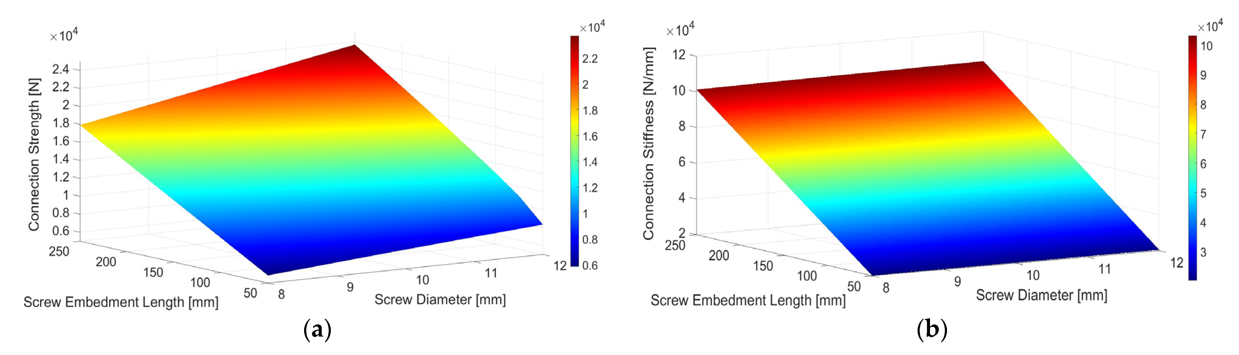
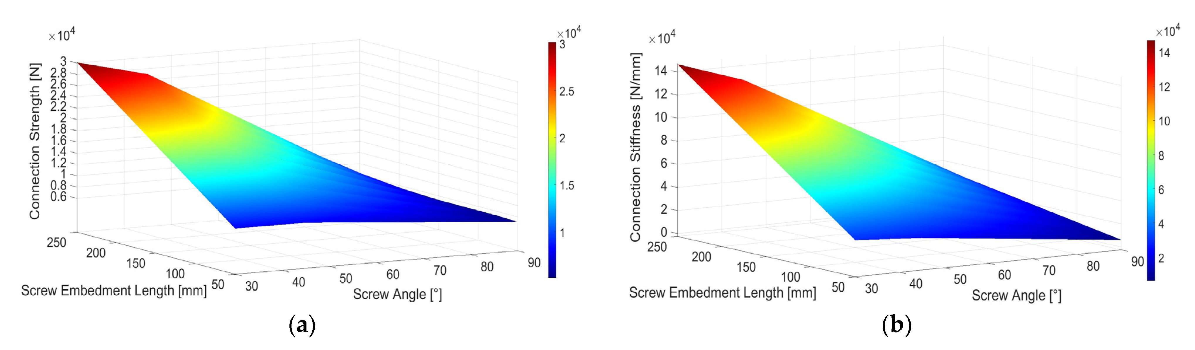
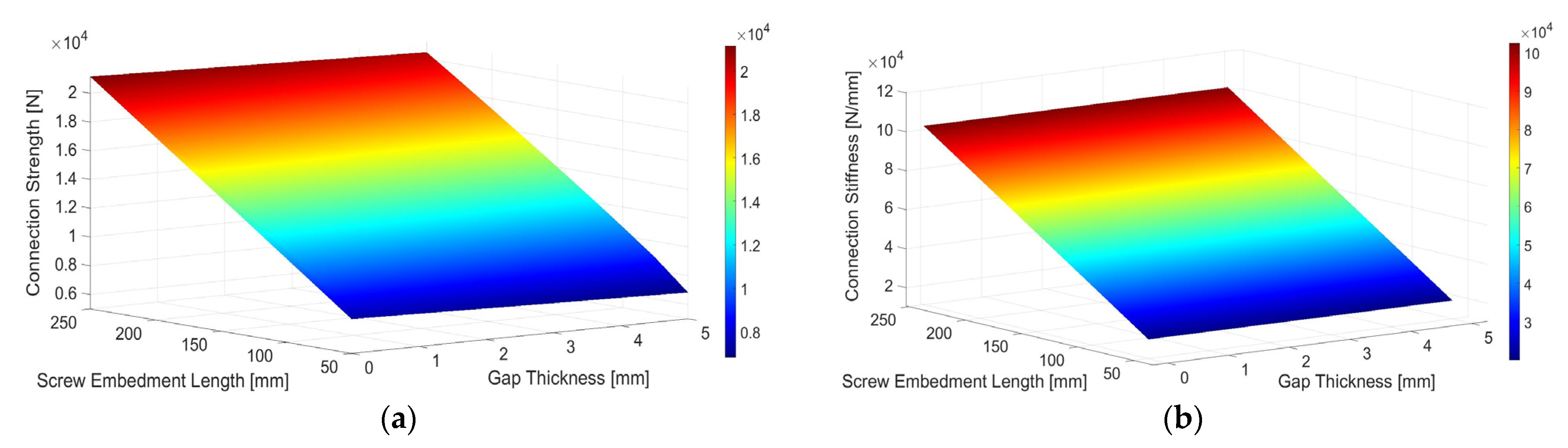
4.1. TCC Connection Behaviour

For the connection behaviour, three main influencing screw parameters are screw embedment length into timber, screw diameter, and screw insertion angle with timber grain. Initially from the parametric analysis, the most sensitive parameter was identified, which significantly influences the connection properties. In this regard, screw embedment into timber was found most sensitive, and thereafter, all the plots were created with a designated axis for screw embedment length. Other parameters were then compared against this base parameter. As can be seen in Figure 9, nominal screw diameter was found somewhat sensitive to the connection strength compared to the stiffness. Connection strength was found increasing with the increase in screw embedment length and diameter, but connection stiffness was found to increase with only the increase in screw embedment length and a negligible amount of increase for screw diameter. This is because, from [39,46], it was found that embedment and withdrawal strength/stiffness properties of the screw are more sensitive to screw embedment length than the screw diameter. This sensitivity is reflected in the connection strength and stiffness behaviour. All things considered, friction is an important parameter which influences the connection stiffness more than strength [27], but in this analysis, the friction was assumed to be zero, which impacted the connection stiffness behaviour for screw diameter. On the other hand, screw insertion angle is very important for connection behaviour as the stiffness and strength properties increase significantly at 30° and 45° insertion angles, which becomes more significant with the increase in embedment length, as can be seen in Figure 10. This is because, at a small insertion angle, the withdrawal properties of screws are more dominant than the embedment properties, which eventually affect the connection behaviour. This connection behaviour through the parametric analysis also agrees well with the connection test from different studies in the literature [7,23,24,25].
Timber density is another important parameter which influences the connection stiffness more than connection strength with the increase in screw embedment length, as can be seen in Figure 11. This is because the embedment and withdrawal stiffness are more susceptible to the timber density at larger embedment lengths than at smaller embedments [39], which influences the connection behaviour. The insulation gap becomes more significant once the friction between timber and concrete is considered in the calculation of connection properties without insulation [27]. In this analysis, the friction was set to zero, which eventually impacted the connection behaviour with a very small decrease due to the presence of a 5 mm insulation gap, as can be seen in Figure 12. Otherwise, from the connection test, a significant decrease in connection stiffness was observed due to the presence of insulation gaps [7]. Overall, among all the parameters, screw embedment length and screw insertion angle are the most influential parameters that affect the TCC connection behaviour.

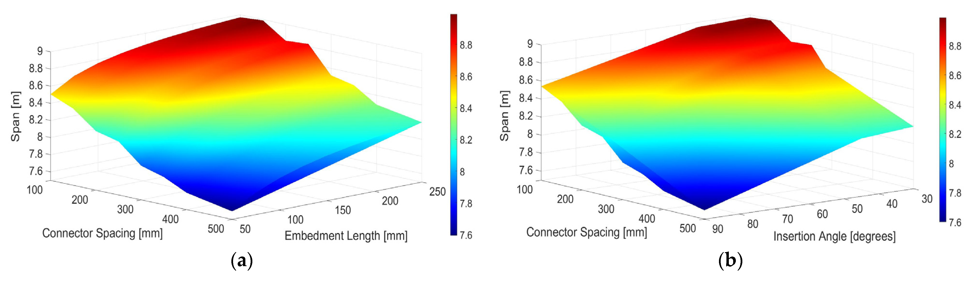
4.2. TCC System Behaviour

Similar to the connection behaviour, the most influential parameters were identified from the parametric analysis from a system behaviour perspective. In this regard, connector spacing was found the most sensitive compared to all other parameters, and therefore, all the plots were created with a designated axis for screw embedment length for comparison of the system behaviour. From the connection behaviour, it was observed that the screw embedment length and screw insertion angle were the most important screw parameters, rather than the screw diameter, to influence the connection properties. This finding is reflected in the system behaviour, as can be seen in Figure 13. The vibration-controlled span increases significantly with the increase in the screw embedment length (Figure 13a) and screw insertion angle (maximum of 30° angle) (Figure 13b). However, the screw diameter in this regard does not affect the TCC span at all (Figure 13c). This result agrees well with the full-scale TCC system test from the literature [23,34,35,47,48,49].
Component thickness is another important influential parameter for TCC system behaviour, as can be seen in Figure 14. Increasing the concrete thickness has a negative impact on the vibration-controlled TCC span due to the reduced frequency caused by extra concrete mass (Figure 14a). Although dense screws along the panel can increase the span, there might be a possibility of concrete cracking as the span at this point barely passed the concrete resistance using the analytical model. In this regard, timber thickness is the most significant parameter which provides a steep increase in system effective bending stiffness and subsequently increases the TCC span, overshooting the connector spacing (Figure 14b). With the presence of dense screw spacing, the thicker timber member further increases the span. This agrees well with the study conducted by the authors to investigate the sustainability design consideration of TCC floors [50].
Similar to the connection behaviour, the TCC floor span does not change when a 5 mm insulation gap is introduced (Figure 14c), which is due to the consideration of zero friction between the timber and concrete surface as mentioned earlier. The insulation gap, in the meantime, can enhance the acoustic performance of the TCC system significantly [50]. The timber density remains an important parameter to influence the TCC system’s behaviour like the connection (Figure 14d). Overall, among all the influencing parameters, the screw spacing, and timber thickness are the most sensitive parameters which significantly affect the TCC system’s behaviour.

5. Conclusions

The major aim of this study was to demonstrate an analytical procedure for designing a timber–concrete composite (TCC) system with mechanical connectors and to investigate the TCC connection and system behaviour for different component parameters using the procedure. In the analytical model, all the relevant factors influencing the analysis of the TCC system, including concrete cracking and long-term performance, were considered by incorporating adjustment factors for connection and component properties. This approach is limited to simply supported TCC beams under uniformly distributed loads and one-way action, which represents the most practical scenario. The approach can be equally applicable to TCC with mass timber beam, mass timber panel, and structural composite lumber with any type of dowel-type mechanical fasteners. The study can be extended further for multiple spanning and other loading scenarios. General TCC connection and system behaviours were extrapolated by performing extensive parametric studies following the analytical procedure. It was concluded that the TCC connection with MTP is most vulnerable to the screw embedment length and insertion angle, while the TCC system is most vulnerable to the screw spacing and timber thickness. This analytical procedure, along with the analyzed TCC behaviour, will facilitate the use of the TCC system in modern mass timber construction.

Author Contributions

Conceptualization, M.A.H.M.; methodology, M.A.H.M. and Y.H.C.; software, R.K.; data curation, R.K.; formal analysis, R.K.; investigation, M.A.H.M.; visualization, M.A.H.M.; validation, M.A.H.M. and Y.H.C.; funding acquisition, Y.H.C.; project administration, Y.H.C.; resources, Y.H.C.; supervision, Y.H.C.; writing—original draft, M.A.H.M.; writing—review and editing, Y.H.C. All authors have read and agreed to the published version of the manuscript.

Funding

The work was funded by a grant from the Natural Sciences and Engineering Research Council of Canada (NSERC) through Industrial Research Chair (IRC) Program.

Institutional Review Board Statement

Not applicable.

Informed Consent Statement

Not applicable.

Data Availability Statement

All data, models, and code generated or used during the study appear in the submitted article.

Acknowledgments

The authors would like to thank Rotho Blaas for their technical support in this study.

Conflicts of Interest

The authors declare that they have no conflict of interest.

References

  1. Mirdad, M.A.H. Structural Performance of Mass Timber Panel-Concrete (MTPC) Composite Floor System with Inclined Self-tapping Screws and an Insulation Layer. Ph.D. Thesis, Department of Civil & Environmental Engineering, University of Alberta, Edmonton, AB, Canada, 2020. [Google Scholar]
  2. Ceccotti, A. Composite concrete-timber structures. Struct. Eng. Mater. 2002, 2002, 264–275. [Google Scholar] [CrossRef]
  3. Yeoh, D.; Fragiacomo, M.; De Franceschi, M.; Boon, K.H. State of the Art on Timber-Concrete Composite Structures: Literature Review. J. Struct. Eng. 2011, 137, 1085–1095. [Google Scholar] [CrossRef]
  4. Dias, A.; Skinner, J.; Crews, K.; Tannert, T. Timber-concrete-composites increasing the use of timber in construction. Holz Roh Werkst. 2015, 74, 443–451. [Google Scholar] [CrossRef]
  5. Dias, A.; Schänzlin, J.; Dietsch, P. Design of Timber-Concrete Composite Structures; Action FP1402/WG 4, COST; European Cooperation in Science and Technology: Aachen, Germany, 2018. [Google Scholar]
  6. Deam, B.L.; Fragiacomo, M.; Buchanan, A.H. Connections for composite concrete slab and LVL flooring systems. Mater. Struct. 2007, 41, 495–507. [Google Scholar] [CrossRef]
  7. Mirdad, M.A.H.; Chui, Y.H. Load-slip performance of Mass Timber Panel-Concrete (MTPC) composite connection with self-tapping screws and insulation layer. Constr. Build. Mater. 2019, 213, 696–708. [Google Scholar] [CrossRef]
  8. Dietsch, P.; Brandner, R. Self-tapping screws and threaded rods as reinforcement for structural timber elements—A state-of-the-art report. Constr. Build. Mater. 2015, 97, 78–89. [Google Scholar] [CrossRef]
  9. Cuerrier-Auclair, S. Design Guide for Timber-Concrete Composite Floors in Canada; Special Publication SP-540E; FPInnovations: Pointe-Claire, QC, Canada, 2020. [Google Scholar]
  10. ETA-19/0244; Rotho Blaas CTC Screw, Self-Tapping Screws for Use in Wood-Concrete Slab Kits. European Technical Assessment: Copenhagen, Danmark, 2019.
  11. ETA-13/0699; SFS VB Screws, SFS VB Screws as Fasteners in Wood-Concrete Composite Slab Kit. European Technical Assessment: Copenhagen, Danmark, 2018.
  12. Bejtka, I.; Blass, H. Joints with inclined screws. In Proceedings of the 35 International Council for Research and Innovation in Building and Construction, CIB W18—Timber Structures, Paper 38-7-5, Universität Karlsruhe, Karlsruhe, Germany, September 2002. [Google Scholar]
  13. Kevarinmäki, A. Joints with inclined screws. In Proceedings of the 35 International Council for Research and Innovation in Building and Construction, CIB–W18—Timber Structures, Paper 35-7-4, Universität Karlsruhe, Karlsruhe, Germany, September 2002. [Google Scholar]
  14. Tomasi, R.; Crosatti, A.; Piazza, M. Theoretical and experimental analysis of timber-to-timber joints connected with inclined screws. Constr. Build. Mater. 2010, 24, 1560–1571. [Google Scholar] [CrossRef]
  15. Jockwer, R.; Steiger, R.; Frangi, A. Fully Threaded Self-Tapping Screws Subjected to Combined Axial and Lateral Loading with Different Load to Grain Angles; Springer: Dordrecht, The Netherlands, 2014; pp. 265–272. [Google Scholar] [CrossRef]
  16. Schiro, G.; Giongo, I.; Sebastian, W.; Riccadonna, D.; Piazza, M. Testing of timber-to-timber screw-connections in hybrid configurations. Constr. Build. Mater. 2018, 171, 170–186. [Google Scholar] [CrossRef]
  17. Ringhofer, A.; Schickhofer, G.; Brandner, R. Axially-Loaded Self-Tapping Screws in Solid Timber and Laminated Timber Products; Monographic Series TU Graz: Timber Engineering & Technology; Verlag der Technischen Universität Graz: Graz, Austria, 2017; Volume TET 5. [Google Scholar]
  18. Sandhaas, C.; Munch-Andersen, J.; Dietsch, P. Design of Connections in Timber Structures; A state-of-the-art report by COST Action FP1402/WG 3; Shaker Verlag: Aachen, Germany, 2018. [Google Scholar]
  19. Bejtka, I. Reinforcement of Wooden Components with Fully Threaded Screws. Ph.D. Thesis, Department of Timber Construction and Structures, Universtität Karlsruhe, Karlsruhe, Germany, 2005. [Google Scholar]
  20. Bejtka, I.; Blaß, H. Self-tapping screws as reinforcements in connections with dowel-type fasteners. In Proceedings of the 38 International Council for Research and Innovation in Building and Construction, CIB–W18—Timber Structures, Paper 38-7-4, Universität Karlsruhe, Karlsruhe, Germany, August 2005. [Google Scholar]
  21. Blass, H.; Bejtka, I.; Uibel, T. Load Capacity of Connection with Self-Drilling Wood Screws with Full Thread; Universität Karlsruhe: Karlsruhe, Germany, 2006. [Google Scholar]
  22. Kavaliauskas, S.; Kazimieras-Kvedaras, A.; Valiunas, B. Mechanical behaviour of timber-to-concrete connections with inclined screws. J. Civ. Eng. Manag. 2007, 13, 193–199. [Google Scholar] [CrossRef]
  23. Gerber, A. Timber-concrete composite connectors in flat-plate engineered wood products. Master’s Thesis, Department of Civil Engineering, University of British Colombia, Vancouver, BC, Canada, 2016. [Google Scholar]
  24. Marchi, L.; Scotta, R.; Pozza, L. Experimental and theoretical evaluation of TCC connections with inclined self-tapping screws. Mater. Struct. 2017, 50, 180. [Google Scholar] [CrossRef]
  25. Appavuravther, E.; Vandoren, B.; Henriques, J. Behaviour of screw connections in timber-concrete composites using low strength lightweight concrete. Constr. Build. Mater. 2021, 286, 122973. [Google Scholar] [CrossRef]
  26. Mirdad, M.A.H.; Chui, Y.H. Strength prediction of mass-timber panel-concrete composite connection with inclined screws and a gap. J. Struct. Eng. 2020, 146, 04020140. [Google Scholar] [CrossRef]
  27. Mirdad, M.A.H.; Chui, Y.H. Stiffness prediction of Mass Timber Panel-Concrete (MTPC) composite connection with inclined screws and a gap. Eng. Struct. 2020, 207, 110215. [Google Scholar] [CrossRef]
  28. EN 1995-1-1; Eurocode 5: Design of Timber Structures Part 1-1: General-Common Rules and Rules for Buildings. European Committee for Standardization: Brussels, Belgium, 2009.
  29. EN 26891; Timber structures—Joints made with mechanical fasteners—General Principles for the Determination of Strength and Deformation Characteristics. European Committee for Standardization: Brussels, Belgium, 1991.
  30. Van der Linden, M. Timber-Concrete Composite Floor Systems. Ph.D. Thesis, Department of Civil Engineering, Delft University of Technology, Delft, The Netherlands, 1999. [Google Scholar]
  31. Frangi, A.; Fontana, M. Elasto-Plastic Model for Timber-Concrete Composite Beams with Ductile Connection. Struct. Eng. Int. 2003, 13, 47–57. [Google Scholar] [CrossRef]
  32. Girhammar, U.A. A simplified analysis method for composite beams with interlayer slip. Int. J. Mech. Sci. 2009, 51, 515–530. [Google Scholar] [CrossRef]
  33. Zhang, C.; Gauvreau, P. Timber-Concrete Composite Systems with Ductile Connections. J. Struct. Eng. 2015, 141, 04014179. [Google Scholar] [CrossRef]
  34. Mirdad, M.A.H.; Chui, Y.H.; Tomlinson, D. Capacity and Failure-Mode Prediction of Mass Timber Panel–Concrete Composite Floor System with Mechanical Connectors. J. Struct. Eng. 2021, 147, 04020338. [Google Scholar] [CrossRef]
  35. Mirdad, M.A.H.; Chui, Y.H.; Tomlinson, D.; Chen, Y. Bending Stiffness and Load–Deflection Response Prediction of Mass Timber Panel–Concrete Composite Floor System with Mechanical Connectors. J. Perform. Constr. Facil. 2021, 35, 04021052. [Google Scholar] [CrossRef]
  36. Auclair, S.C.; Sorelli, L.; Salenikovich, A. Simplified nonlinear model for timber-concrete composite beams. Int. J. Mech. Sci. 2016, 117, 30–42. [Google Scholar] [CrossRef]
  37. Fragiacomo, M. A finite element model for long-term analysis of timber-concrete composite beams. Struct. Eng. Mech. 2005, 20, 173–189. [Google Scholar] [CrossRef]
  38. Binder, E.; Derkowski, W.; Bader, T.K. Development of Creep Deformations during Service Life: A Comparison of CLT and TCC Floor Constructions. Buildings 2022, 12, 239. [Google Scholar] [CrossRef]
  39. Mirdad, M.A.H.; Jucutan, A.; Khan, R.; Neiderwestberg, J.; Chui, Y.H. Embedment and Withdrawal Stiffness Predictions of Self- Tapping Screws in Timber. Constr. Build. Mater. 2022; under review. [Google Scholar]
  40. Hu, L.; Cuerrier-Audair, S.; Chui, Y.H.; Ramzi, R.; Gagnon, S.; Mohammad, M.; Ni, C.; Popovski, M. Design method for controlling vibrations of wood-concrete composite floor systems. In Proceedings of the World Conference in Timber Engineering (WCTE), Vienna University of Technology, Vienna, Austria, 22–25 August 2016. [Google Scholar]
  41. CSA-A23.3-14; Design of Concrete Structures. Canadian Standard Association: Mississauga, ON, Canada, 2014.
  42. CSA S16-14; Design of Steel Structures. Canadian Standard Association: Mississauga, ON, Canada, 2014.
  43. Fragiacomo, M.; Lukaszewska, E. Influence of the Construction Method on the Long-Term Behavior of Timber-Concrete Composite Beams. J. Struct. Eng. 2015, 141, 04015013. [Google Scholar] [CrossRef]
  44. CSA O86-19; Engineering Design in Wood. Canadian Standards Association: Mississauga, ON, Canada, 2019.
  45. NBCC. National Building Code of Canada; National Research Council: Ottawa, ON, Canada, 2015. [Google Scholar]
  46. Khan, R.; Niederwestberg, J.; Chui, Y.-H. Influence of insertion angle, diameter and thread on embedment properties of self-tapping screws. Holz Roh Werkst. 2021, 79, 707–718. [Google Scholar] [CrossRef]
  47. Hong, K.E.M. Structural Performance of Nail-Laminated Timber-Concrete Composite Floors. Master’s Thesis, University of British Columbia, Vancouver, BC, Canada, 2017. [Google Scholar]
  48. Lukaszewska, E. Development of Prefabricated Timber-Concrete Composite Floors. Ph.D. Thesis, Luleå University of Technology, Luleå, Sweden, 2009. [Google Scholar]
  49. Chuan, D.Y.E. Behaviour and Design of Timber-Concrete Composite Floor System. Ph.D Thesis, University of Canterbury, Christchurch, New Zealand, 2010. [Google Scholar]
  50. Mirdad, M.A.H.; Daneshvar, H.; Joyce, T.; Chui, Y.H. Sustainability design considerations for timber-concrete composite (TCC) floor systems. Adv. Civ. Eng. 2021, 2021, 6688076. [Google Scholar] [CrossRef]
Figure 1. Longitudinal section of a TCC system with dowel, notched, or proprietary connector.
Buildings 12 00885 g001
Figure 2. Timber–concrete composite (TCC) system analysis flowchart.
Buildings 12 00885 g002
Figure 3. Timber–concrete composite (TCC) system with dowel-type mechanical fasteners: (a) longitudinal section, (b) cross-section with timber beam, and (c) cross-section with mass timber panel/structural composite lumber.
Buildings 12 00885 g003
Figure 4. Timber–concrete composite (TCC) system response: (a) primary system with uniform load, (b) sub-system 1 with fully non-composite action, and (c) sub-system 2 with unknown shear forces.
Buildings 12 00885 g004
Figure 5. Stress distributions in concrete-to-timber connection with an inclined dowel type mechanical fastener for failure: (a) mode 1—embedment of fastener, (b) mode 2—embedment of fastener plus single plastic hinge, and (c) mode 3—embedment of fastener plus double plastic hinge.
Buildings 12 00885 g005
Figure 6. Stress distributions in TCC system with mass timber beam.
Buildings 12 00885 g006
Figure 7. Stress distributions in TCC system with mass timber panel or structural composite lumber.
Buildings 12 00885 g007
Figure 8. Effective width of the concrete slab in TCC with timber beams.
Buildings 12 00885 g008
Figure 9. Connection, (a) strength, and (b) stiffness for different screw embedment length vs. screw diameter.
Buildings 12 00885 g009
Figure 10. Connection, (a) strength, and (b) stiffness for different screw embedment length vs. screw angle.
Buildings 12 00885 g010
Figure 11. Connection, (a) strength, and (b) stiffness for different screw embedment length vs. timber density.
Buildings 12 00885 g011
Figure 12. Connection, (a) strength, and (b) stiffness for different screw embedment length vs. gap thickness.
Buildings 12 00885 g012
Figure 13. TCC span for different (a) connector spacing vs. embedment length, (b) connector spacing vs. insertion angle, and (c) connector spacing vs. diameter.
Buildings 12 00885 g013aBuildings 12 00885 g013b
Figure 14. TCC span for different (a) connector spacing vs. concrete thickness, (b) connector spacing vs. timber thickness, (c) connector spacing vs. gap thickness, and (d) connector spacing vs. timber density.
Buildings 12 00885 g014
Table 1. Input parameters into the TCC connection and system model.
ParametersUnitsValue
Timber Densitykg/m3425 (SPF) and 525 (DF)
Screw Diametermm8, 9, 10, 11, and 12
Screw Insertion Angledegree30, 45, 60, and 90
Screw Embedment Lengthmm50, 100, 150, 200, and 250
Screw MOEGPa210
Screw Spacingmm100, 150, 200, 250, 300, 350, 400, 450, and 500
Gap Thicknessmm0 and 5
MTP Thicknessmm80, 130, 175, and 215 (GLT)
105, 175, 245, and 315 (CLT)
MTP Widthmm1000
MTP MOEMPa9500 (SPF) and 11,000 (DF)
Concrete Thicknessmm50, 75, and 100
Concrete Widthmm1000
Concrete StrengthMPa35
Publisher’s Note: MDPI stays neutral with regard to jurisdictional claims in published maps and institutional affiliations.

