Article

Analysis of Seismic Isolation Performance of X-Shaped Rubber Bearings (XRBs)

1
Engineering Research & Test Center, Guangzhou University, Guangzhou 510405, China
2
State Key Laboratory of Subtropical Building Science, South China University of Technology, Guangzhou 510640, China
*
Author to whom correspondence should be addressed.
Buildings 2022, 12(8), 1102; https://doi.org/10.3390/buildings12081102
Submission received: 28 June 2022 / Revised: 21 July 2022 / Accepted: 23 July 2022 / Published: 26 July 2022
(This article belongs to the Special Issue Resilience-Based Structural Seismic Design and Evaluation)

Abstract

:
A detailed analysis of the seismic safety performance of building structures using X-shaped rubber bearings (XRBs) under seismic action at different seismic levels of intensity were carried out in this study. The horizontal mechanical properties of XRB were studied by analytical methods. To reveal the failure prevention and control capability of XRBs under strong ground motions, a detailed comparative analysis was conducted of the seismic performances of three-story buildings using XRBs, typical rubber bearings (TRBs), and TRBs with retaining wall protection (RWP). A nonlinear dynamic finite element method was used to analyze the displacement, velocity, and acceleration responses of the seismically isolated structures at different ground motion intensity levels. The results show that the failure of the seismic isolation layer occurs in the building using TRBs under seismic intensity with a 1‱ probability of exceedance (PE) in one year. When the RWP is set around the seismic isolation layer, the superstructure will collide with the wall, which leads to a dramatic increase in superstructure acceleration, while the overall seismic isolation performance of the structure is affected. Nevertheless, XRBs can effectively prevent deformation failure of the seismic isolation layer of a building, reduce the seismic response of a superstructure, and can improve the seismic safety level of a building.

1. Introduction

With the frequent occurrence of earthquake disasters around the world, the issue of seismic safety of building structures has gained widespread attention [1,2]. Base isolation technology has proven to be a feasible method to deal with earthquake damage [3,4]. The purpose of base isolation is mainly to set the isolation layer between the foundation and a superstructure. A lower stiffness of the isolation layer can prolong the structural period and can reduce the seismic energy input to a building, therefore, the superstructure can be effectively protected and its seismic performance can be improved. In 1921, the Imperial Hotel in Japan used soft soil geological conditions to form a natural isolation pad, and it was considered to be one of the first buildings to use seismic isolation [5]. As seismically isolated buildings have shown excellent seismic performance during earthquakes, seismic isolation technology has been developed rapidly in recent years. Some structural engineers have decreased the seismic response of a superstructure by reducing the horizontal stiffness of the columns on the first floor. Although the expected effect can be achieved, in practice, the first-floor column was seriously damaged [6,7]. Since then, researchers have also carried out research on rolling isolators, but the isolation effects of the structures were not satisfactory [8,9].
Since rubber has been used in isolation devices, isolation technology has been significantly developed. To ensure the seismic safety of an elementary school in Skopje, Yugoslavia, large pieces of pure natural rubber were installed at the base of the building [10]. The horizontal and vertical stiffness of rubber bearings are approximately the same, which results in swaying of buildings. Therefore, researchers began to strengthen the vertical stiffness of rubber bearings, and thereafter, laminated rubber vibration isolation bearings were proposed, consisting of steel plates and rubber placed alternately and bonded by vulcanization. This type of bearing provides sufficient vertical stiffness and load capacity.
Research on laminated rubber bearings and their applications has been started in many countries. A three-story school in Marseilles, France, adopted an isolation system of laminated rubber bearings, which met the seismic design requirements of the region [11]. The first base isolation building in the United States used 98 laminated rubber isolation bearings, resulting in a safer building in earthquakes [12]. Seismic isolation technology was used at the Lushan County Hospital in China, and the building survived the Lushan earthquake without damage to structural and non-structural components, which played a key role in the post-earthquake rescue.
With intensive research on rubber isolation bearings, various rubber bearings have been developed. For example, Robinson and Tucker [13] proposed a lead rubber bearing, by inserting a lead rod in the middle of the laminated rubber bearing, which provided damping to consume seismic energy. Similarly, damping rubber produced by adding a compound to rubber has been applied to laminated rubber bearings to form high-damping laminated rubber bearings [14]. Wu et al. [15] studied FRP-laminated rubber isolation bearings and found that isolation bearings had the characteristics of low horizontal stiffness, considerable energy consumption capacity, and easy construction.
Seismic performance studies of foundation isolation structures have revealed that the deformation of the whole isolation system occurs mainly on the isolation bearings, and the deformation of the superstructure is small [16,17]. During the East Japan earthquake in 2011, rubber bearings suffered horizontal shear failure due to large horizontal deformation, which exceeded the deformation capacity of the rubber [18]. Li et al. [19] conducted an experimental study on high-damping laminated rubber bearings, which showed that the bearings were damaged when the shear deformation was 350% under the vertical stress of 6 MPa. Montuori et al. [20] studied the stability of bearings under compression and shear, and showed that the second shape factor S2 of the bearing was the main factor affecting the stability and shear failure mode of a bearing under large lateral displacement. Kurihara et al. [21] found that the horizontal stiffness of a rubber bearing decreased with an increase in horizontal displacement, and the vertical mechanical properties of the bearing were reduced under large deformation. Wu et al. [22] proposed a modified probabilistic demand model considering site effects and used it for the study of seismic isolated bridges for high-speed railways; the analysis showed that the horizontal deformation of the seismic isolation bearing increased significantly under soft soil site conditions. Therefore, there is a need to improve the deformation capacity of isolation bearings, which is related to the safety of the isolation bearings and the isolation structure.
Therefore, an unbonded steel mesh-reinforced rubber bearing was investigated, and a shaking table test of an isolated steel beam bridge showed that the bearing could maintain the stability of lateral deformation under a strong earthquake [23]. Wang et al. [24] proposed using polyurethane elastomer to replace the rubber in a laminated rubber bearing, and the research showed that the bearing had large vertical bearing capacity, and its ultimate deformation capacity was improved. In order to improve the deformation of lead rubber bearings under a strong earthquake, Choi et al. [25] embedded shape memory alloy wire into a rubber bearing, and found that the bearing effectively limited the relative displacement of the bearing under a strong earthquake. Aiming at the problem that the base displacement of an isolated structure may exceed its design limit, Du et al. [26] set a displacement limiter outside an isolated bearing, and the test showed that this method could effectively limit the response of the base displacement of the isolated structure.
In actual projects, laminated rubber bearings are widely used. However, laminated rubber bearings are prone to failure defects under large deformations. Clark et al. [27] used shape memory alloy (SMA) wrapped around rubber as seismic isolation bearings, and the experimental results showed that SMA dampers could reduce the seismic isolation layer displacement under certain temperature variation, loading frequency, and strain amplitude. Desroches and Delemont [28] used SMA rods both as limiters and dampers for a multi-span simply supported bridge structure, and the analysis of the bridge response under ground shaking showed that SMA was effective as a limiter. Ismail et al. [29] proposed a seismic isolation bearing called the roll-in-cage (RNC) bearing, which limited the design displacement through a built-in energy absorbing cushion and a built-in linear elastic device to reduce the residual displacement. However, the method of improving rubber material and combining it with other devices to limit bearing deformation is often complicated during the construction process and is less used in practical engineering.
To solve the failure of TRB bearings under conditions of earthquakes exceeding the fortification intensity, based on an analysis of the structural mechanical properties of existing rubber bearings (TRB) [30,31,32], an X-shaped rubber bearing (XRB) with a high level of deformation limits was proposed by [33]. However, the seismic isolation performance of the building structure using XRB under the seismic action of the fortification intensity and exceeding the fortification intensity was uncertain, and whether XRB could improve the seismic safety performance of an isolated structure as compared with TRB is yet to be determined. This study analyzed the horizontal stiffness of the bearings based on calculations of the structural characteristics of the XRB. Then, the seismic responses of three types of seismically isolated building structures, including those using XRB, TRB, and TRB with retaining wall protection (RWP), were compared based on finite element analysis (FEA) methods. Finally, the seismic responses of the seismically isolated structures were simulated using nonlinear dynamic time-history analysis, and the seismic isolation performance of the XRB was analyzed by comparing the deformation of the responses of the different types of structures.

2. Introduction of XRB’s Features

2.1. Design Features

Compared to the TRB, the XRB has a revised external shape, with the top and bottom of the bearing designed as a circular platform. The three-dimensional appearance of the XRB is shown in Figure 1a, and the longitudinal section is shown in Figure 1b. As shown in Figure 1b, the longitudinal section of XRB has an X-shaped appearance. The seismic isolator consists of an upper sealing plate, a lower sealing plate, and an X-shaped steel reinforced laminated rubber elastomer.
Under horizontal seismic load, shear deformation occurs in the seismic isolation bearing. When the horizontal deformation of the rubber bearing gradually increases, the effective load-bearing area gradually decreases. When the vertical force remains unchanged, the effective vertical compressive stress on the effective bearing area gradually increases. This effective vertical compressive stress and the increase in shear deformation eventually led to failure of the bearing. Therefore, increasing the effective bearing area is the key. Generally speaking, the horizontal shear deformation at the top and bottom of the bearing is larger than that at the middle part. XRB can make the bearing have a larger effective bearing area by increasing the cross-sectional area at the top and bottom of the bearing. By comparing with TRB, XRB can increase the effective bearing area and can reduce the concentrated vertical stress of the bearing in compression-shear condition. In general, this XRB can improve the ultimate bearing capacity and ultimate deformation capacity of the bearing.

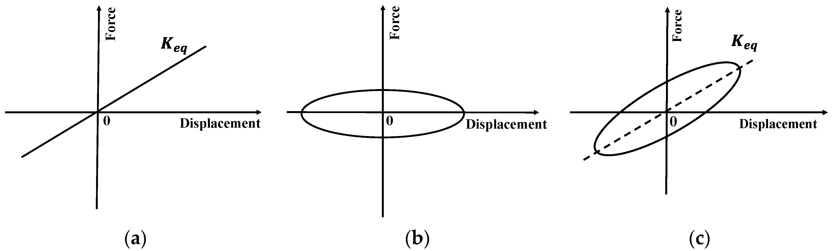
2.2. Horizontal Mechanical Properties of XRB

Assuming that the influence of vertical compressive stress of the bearing is neglected, the horizontal stiffness of the laminated rubber bearing ( K ) can be expressed as [34]:
K = G A n t r
where G is the shear modulus of rubber, A is the cross-sectional area of bearing, t r is the thickness of single rubber layer, and n is the number of rubber layers.
Assuming that the central symmetry axis of the rubber bearing is the y-axis, the cross section of XRB varies continuously along the y direction. When the height of the bearing is H , the equivalent cross-sectional area of the rubber bearing ( A e q ) can be expressed as:
A e q = V H
where V is the volume of bearing.
It is assumed that the horizontal equivalent stiffness of XRB ( K e q ) is related to the equivalent cross-sectional area ( A e q ) when the shape of the bearing changes along the height. Substituting Equation (2) into Equation (1), K e q can be expressed as:
K e q = G V n t r H
As can be seen from Figure 1, the XRB can be divided into three parts: the upper circular platform, the middle cylinder, and the lower circular platform. Thus, the volume of XRB ( V ) can be expressed as:
V = 2 ( V 1 + V 2 )
where V 1 and V 2 are the volumes of the middle part and the upper or lower circular platform, respectively. As shown in Figure 1b, V 1 and V 2 can be calculated by integrating the shape functions of each part as follows:
V 1 = 0 h 1 / 2 π R 1 2 y d y
V 2 = h 1 / 2 h 1 / 2 + h 2 π R 2 2 y d y
where R 1 y and R 2 y are the shape function of the middle part and the upper or lower part of the XRB, respectively.
Substituting Equations (5) and (6) into Equation (4), V can be expressed as the following equation:
V = 2   ( 0 h 1 2 π R 1 2 y d y + h 1 / 2 h 1 / 2 + h 2 π R 2 2 y d y )
Substituting Equation (7) into Equation (3), the horizontal equivalent stiffness of XRB can be expressed as:
K e q = 2 G ( 0 h 1 2 π R 1 2 y d y + h 1 / 2 h 1 / 2 + h 2 π R 2 2 y d y ) n t r H

3. Finite Element Modeling of Seismically Isolated Buildings

Most of the currently constructed seismically isolated buildings are three- to five-story reinforced concrete (RC) frame structures, while multi-story RC frame structures in earthquake disaster areas are severely damaged [35]. To investigate the failure prevention capability of seismic isolation bearings under strong earthquakes, a typical three-story RC frame isolated building was selected for seismic isolation analysis, which was located on a site with a fortification intensity of VIII and soil site conditions of Class II. This isolation building has a span of 5 m, the height of each floor is 3 m, and the total height is 9 m. The mass of the first floor of the building is 25 t, and that of the 2~3 floors and the roof is 20 t. According to the classification of seismic intensity in China [36], the peak ground acceleration (PGA) of fortification intensity VIII with 2–3% probability of exceedance (PE) in 50 years is 0.4 g, which was used for structural design. It is assumed that each floor has only one horizontal degree of freedom and the effect of soil structure interaction is neglected. In order to evaluate the isolation performance of the XRB, three different isolation buildings are designed: buildings with XRBs (Figure 2a), buildings using TRBs (Figure 2b), and TRBs with RWPs (Figure 2c).

3.1. Design of Isolation Layer

According to the seismic design code, the deformation of the seismic isolation layer of the building with XRB, TRB and TRB with RWP satisfies the requirements of the bearing limit under the rare earthquake action. The size of the rubber bearing is designed according to the weight of the building structure and the vertical compressive stress of the bearing. The total height of the rubber bearing is 85 mm, where the thickness of single rubber layer t r is 2.5 mm, with a total of 20 layers. The G of the rubber in the bearing is 0.40 Mpa. The vertical compressive stress of TRB is 7.50 MPa, and the diameter is 270 mm. Similarly, the specific design parameters of XRB are as follows:
(1)
The total height of the laminated rubber part of the steel plate is 85 mm;
(2)
The h 1 and h 2 are 17 mm and 34 mm, respectively;
(3)
The minimum diameter ( d ) of the bearing is 250 mm, and the large diameter ( d ) of the bearing is 370 mm;
(4)
The compressive stress at the minimum cross-section of the bearing is 8.50 MPa.
According to the above bearing characteristic parameters and Equation (8), the horizontal equivalent stiffnesses of XRB and TRB are calculated to be 0.55 kN/mm and 0.46 kN/mm, respectively.
In seismic isolation design, it is usually necessary to include dampers in the isolation layer to improve the seismic energy consumption efficiency of the isolation layer. In this study, the damping ratio of the seismic isolation layer was designed to be 9% according to the requirement of the deformation limit of the seismic isolation bearing (0.55 times the diameter of the bearing) [37]. Accordingly, the damping coefficient of the viscous dampers was set to 50 N∙s/mm. Figure 3 shows the horizontal force-displacement hysteresis model of the isolation layer including isolation bearings and dampers.

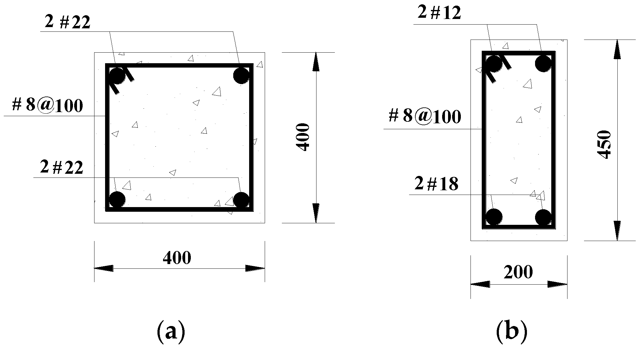
3.2. Structural Parameters and Finite Element Model

The concrete strength grade of the members of a typical building structure is C30, and the axial compressive strength and design compressive strength of its concrete are 20.1 MPa and 14.3 MPa, respectively [38]. The cross-section dimensions of beam and column used for the building structure are shown in Figure 4, where the cross-section of the column is 400 mm × 400 mm and the cross-section of the beam is 200 mm × 450 mm. The longitudinal reinforcement rates of the beams and columns are 0.56% and 0.95%, respectively. The characteristic parameters of the building, including the natural period (NP) of the model structure, are shown in Table 1.
The FEA platform (OpenSees) has a wide range of simulation units, therefore, OpenSees is used to model isolated building structures. For the beams and columns of the frame, displacement-based fiber beam-column units (Dispbeamcolumn) were used and the members were divided by fiber sections. The constitutive relationship of the beam-column concrete was modeled using a modified Kent and Park model [39], i.e., Concrete02 [40,41]. The isotropic Giuffre–Menegotto–Pinto model [42], Steel02 [43], was used for the constitutive relationship of the longitudinal reinforcement of the beams and columns. In the numerical model analysis, the Newmark method of progressive numerical integration was used to solve the nonlinear response of the structure and the norm displacement increment test convergence criterion was used for convergence judgment [44]. In this numerical model, ElasticPPGap elements were used to simulate the gap and collision relationship between the building and the RWP. In order to prevent the horizontal displacement of the seismic isolation layer from exceeding the TRB deformation limit under earthquake action and cause the failure of the bearing, the gap unit displacement was set at 0.55 times the bearing diameter. In addition, the effect of P-Delta was considered in the simulation of the model.

4. Seismic Analysis of Numerical Model

A nonlinear dynamic finite element analysis of a three-story seismically isolated building was conducted based on three natural ground motion acceleration records under typical soil conditions in China. Based on the analysis results, the displacement, velocity, and acceleration responses of the three building structure models were compared under earthquake effects.

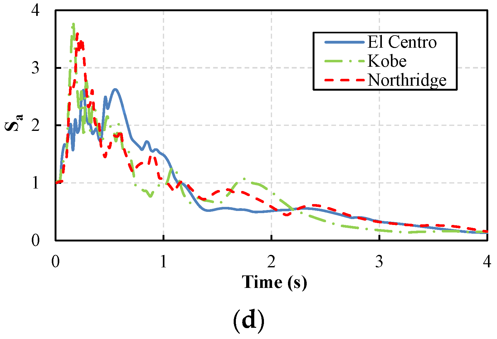
4.1. Input of Ground Motion

Since the typical building is located in soil site category II, the seismic records of three well-known typical earthquakes (El Centro, Kobe, and Northridge earthquakes) selected from the PEER database in soil site category II were selected as input seismic waves. The normalized acceleration time histories and acceleration response spectra (Sa) of representative earthquake records are shown in Figure 5. In the dynamic time history analysis of isolated buildings, the PGA was scaled uniformly for different ground motion levels. According to the classification of seismic intensity in China [36], the PGAs for the fortification intensity Ⅷ with a 2–3% PE in 50 years and a 1‱ PE in one year are 0.4 g and 0.6 g, respectively.

4.2. Analysis Results

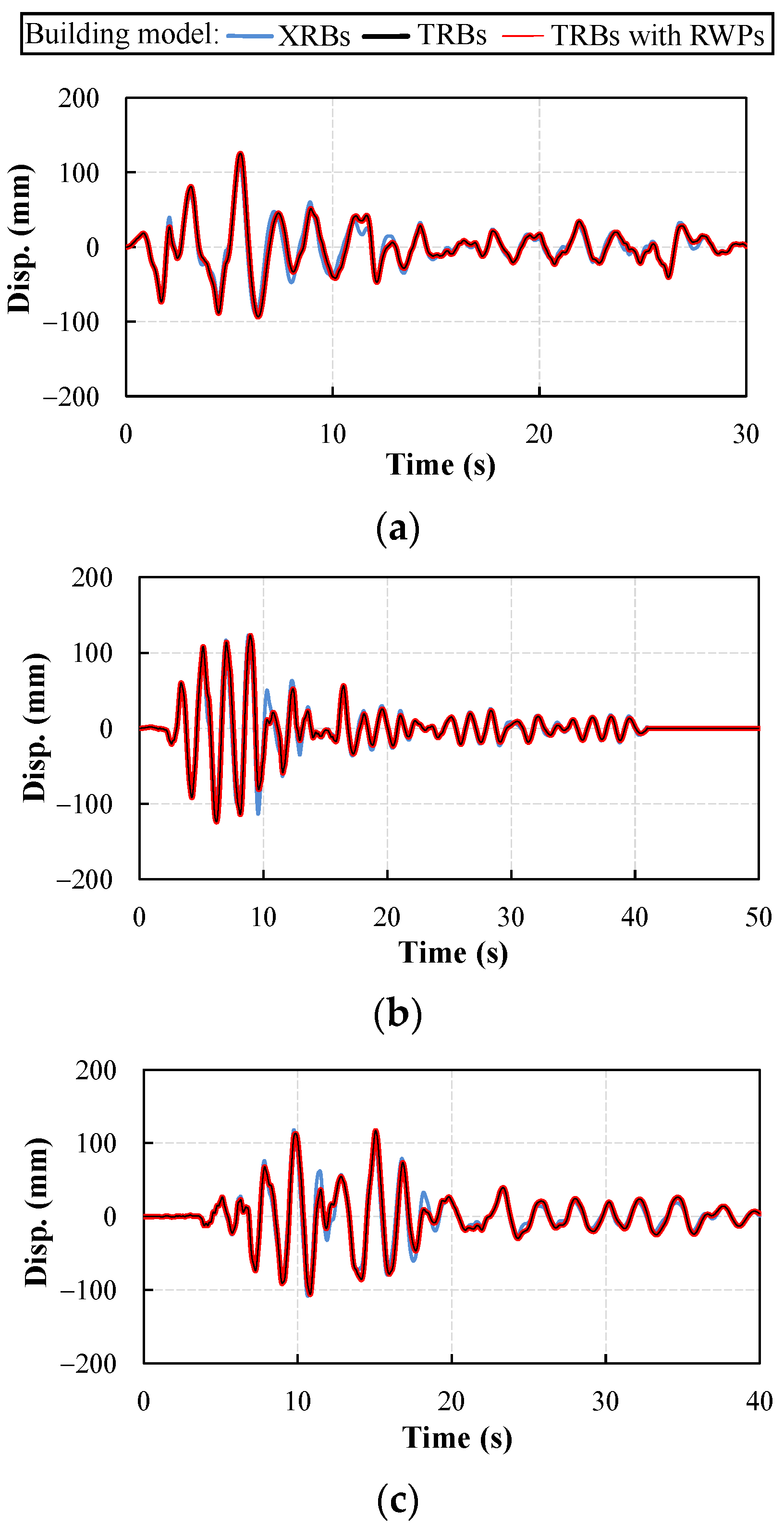
4.2.1. Displacement Response

The horizontal displacement response of isolation bearings is an important index to evaluate the safety performance of isolated buildings. If the horizontal displacement of the isolation layer exceeds the limit value, the bearing will be damaged and fail, resulting in overall collapse of the isolated building. Under earthquakes at the 2–3% PE in 50 years and the 1‱ PE in one year, the dynamic time-history analysis of isolated buildings was carried out. The displacement responses of isolation layers of buildings using XRBs, TRBs, and TRBs with RWPs were obtained, as shown in Figure 6 and Figure 7.
The horizontal shear deformation limit of laminated rubber bearing is 0.55 times the effective diameter. The horizontal deformation limit of TRB with an effective diameter of 270 mm is 148.5 mm. Due to the increase in effective bearing area, the effective diameter of XRB is 370 mm and its horizontal deformation limit is 203.5 mm. It can be seen from Figure 6 that the displacement responses of the isolation layers of different isolated buildings are roughly the same under the ground motions at a 2–3% PE in 50 years, and the isolated buildings meet the basic requirements of seismic safety. As can be seen from Figure 7, for the ground motion of 1‱ PE in one year, the building with TRB reaches the maximum displacement limit of the bearing at 5.36 s, 5.06 s, and 9.70 s corresponding to El Centro, Kobe, and Northridge waves, respectively. At this time, the overall failure of the isolated structure occurred due to the over-limit of the bearing displacements. The maximum bearing displacement response of the building with XRB under earthquake was within 200 mm, and no bearing deformation exceeding the limit that occurred in the finite element dynamic time analysis. The maximum bearing displacement response of buildings using TRBs with RWPs is 148.5 mm, because the use of RWPs prevents displacement failure of bearings.

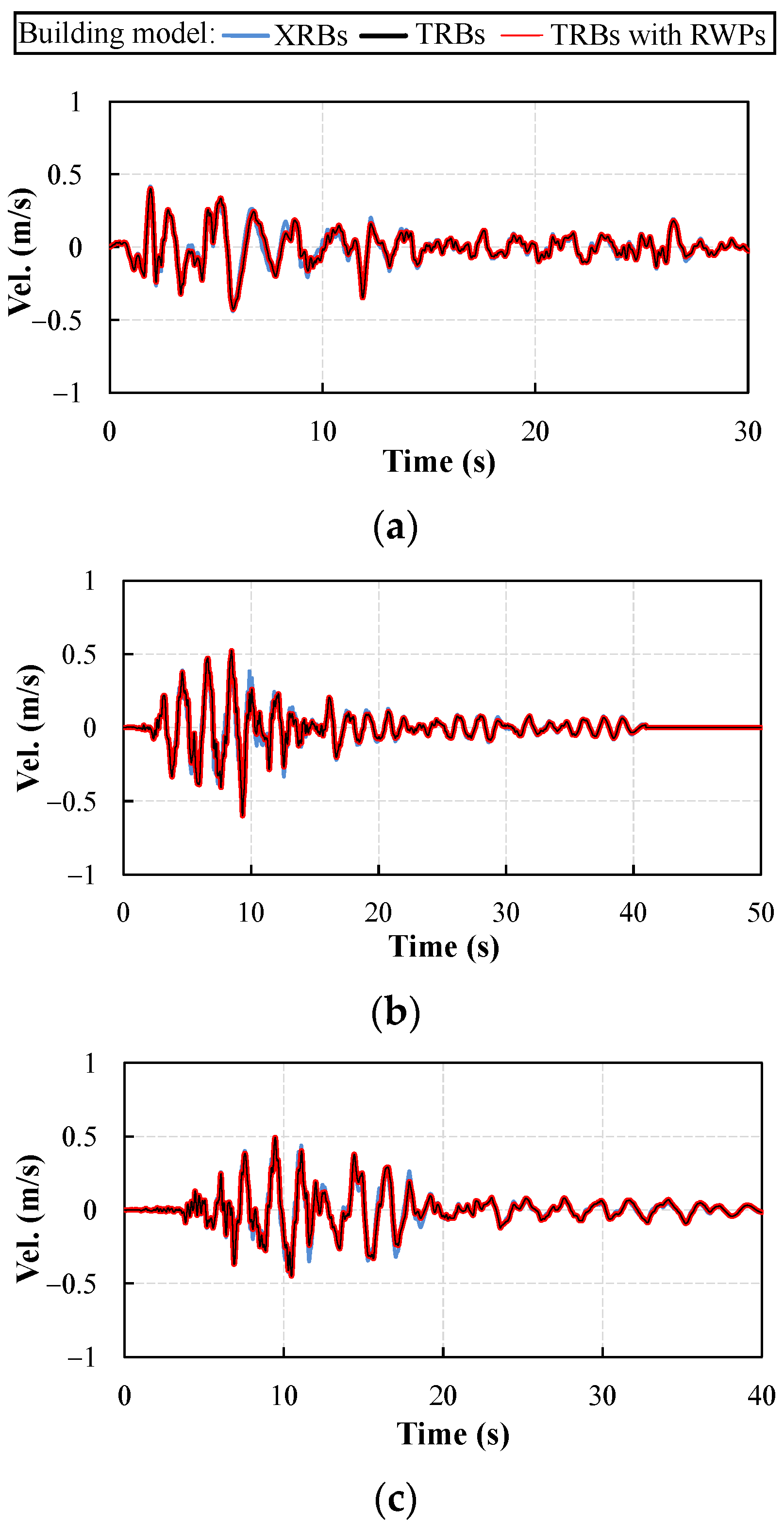
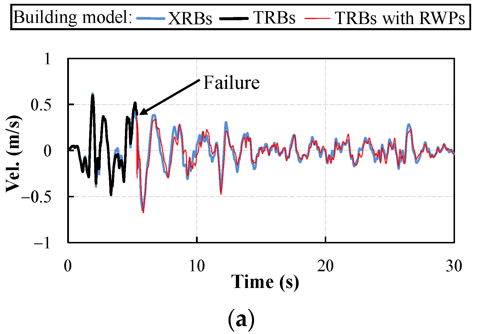
4.2.2. Velocity Response

The velocity response of seismically isolated superstructure has an effect on the structural kinetic energy. The velocity responses of the first floor of buildings using XRBs, TRBs, and TRBs with RWPs are shown in Figure 8 and Figure 9.
It can be seen from Figure 8 that under the ground motions at a 2–3% PE in 50 years, the velocity responses of the different isolation buildings are basically the same. As can be seen in Figure 9, the velocities of the superstructure are high when the TRB reaches the deformation limit under ground motion of 1‱ PE in one year. The first floor velocities at collision of isolated buildings with RWPs are 0.39 m/s, 0.25 m/s, and 0.37 m/s for El Centro, Kobe, and Northridge seismic waves, respectively.

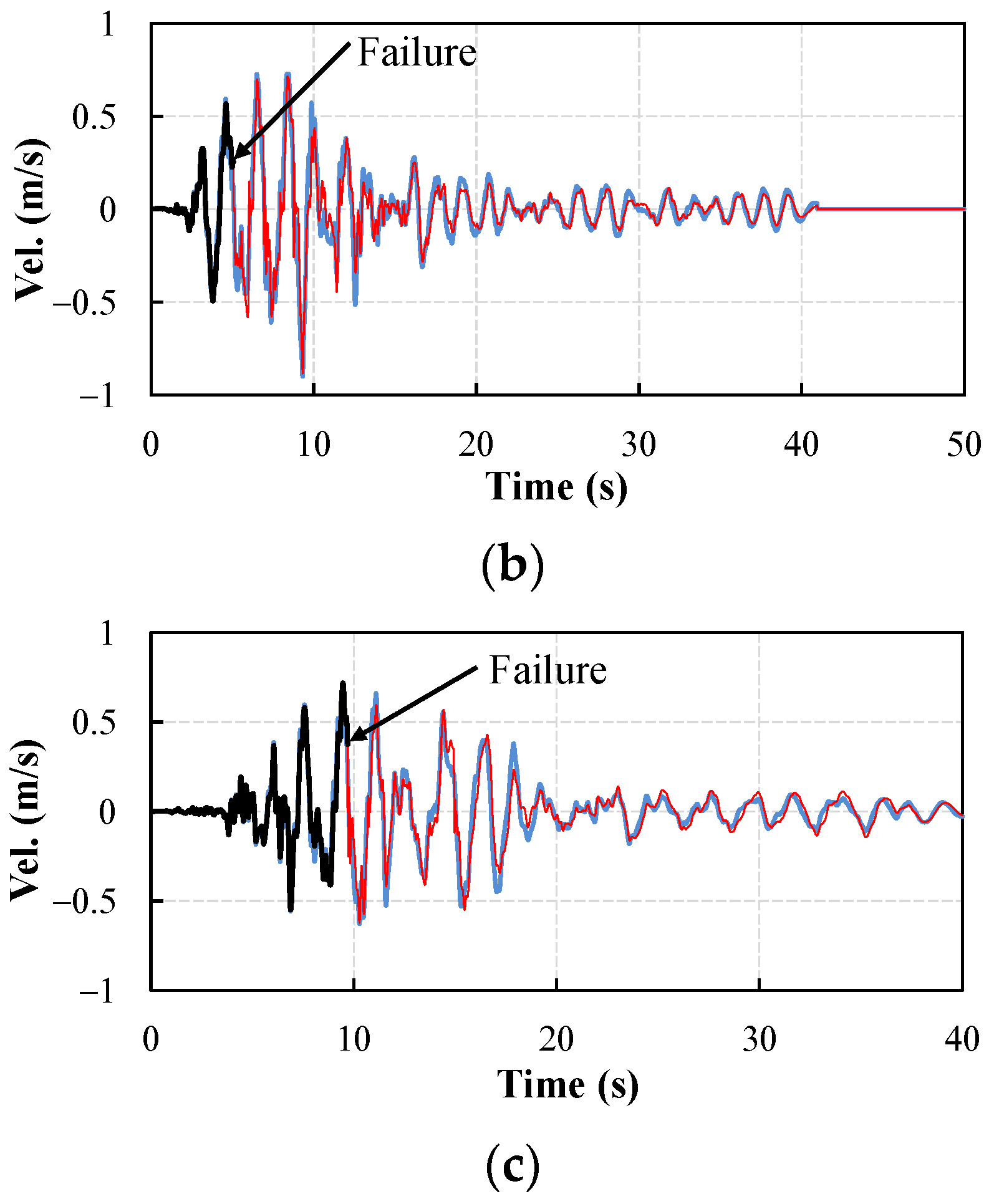
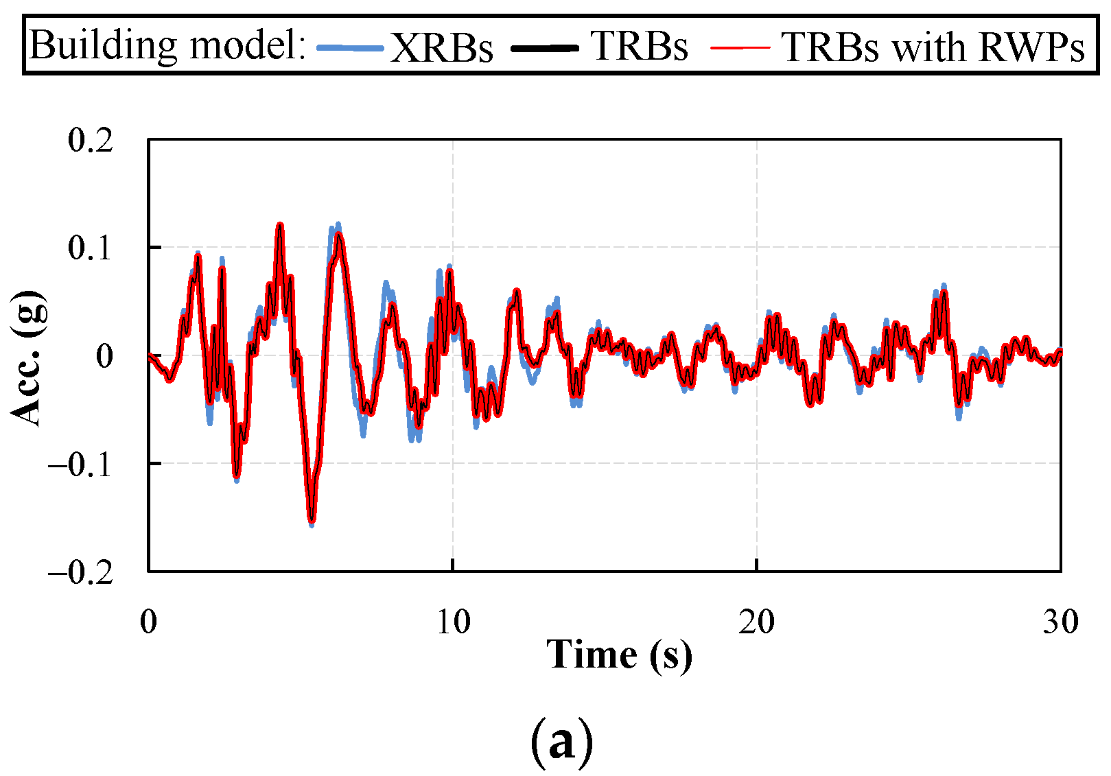
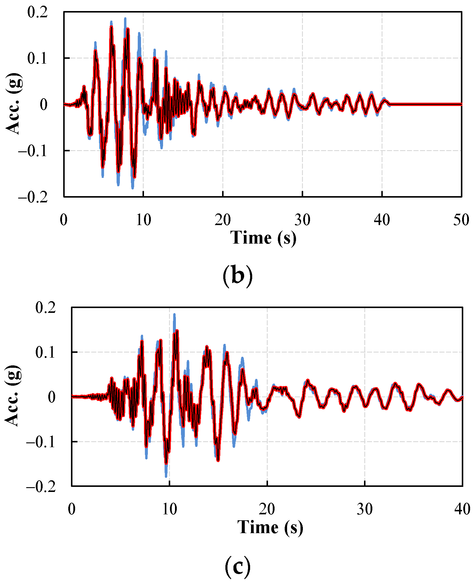
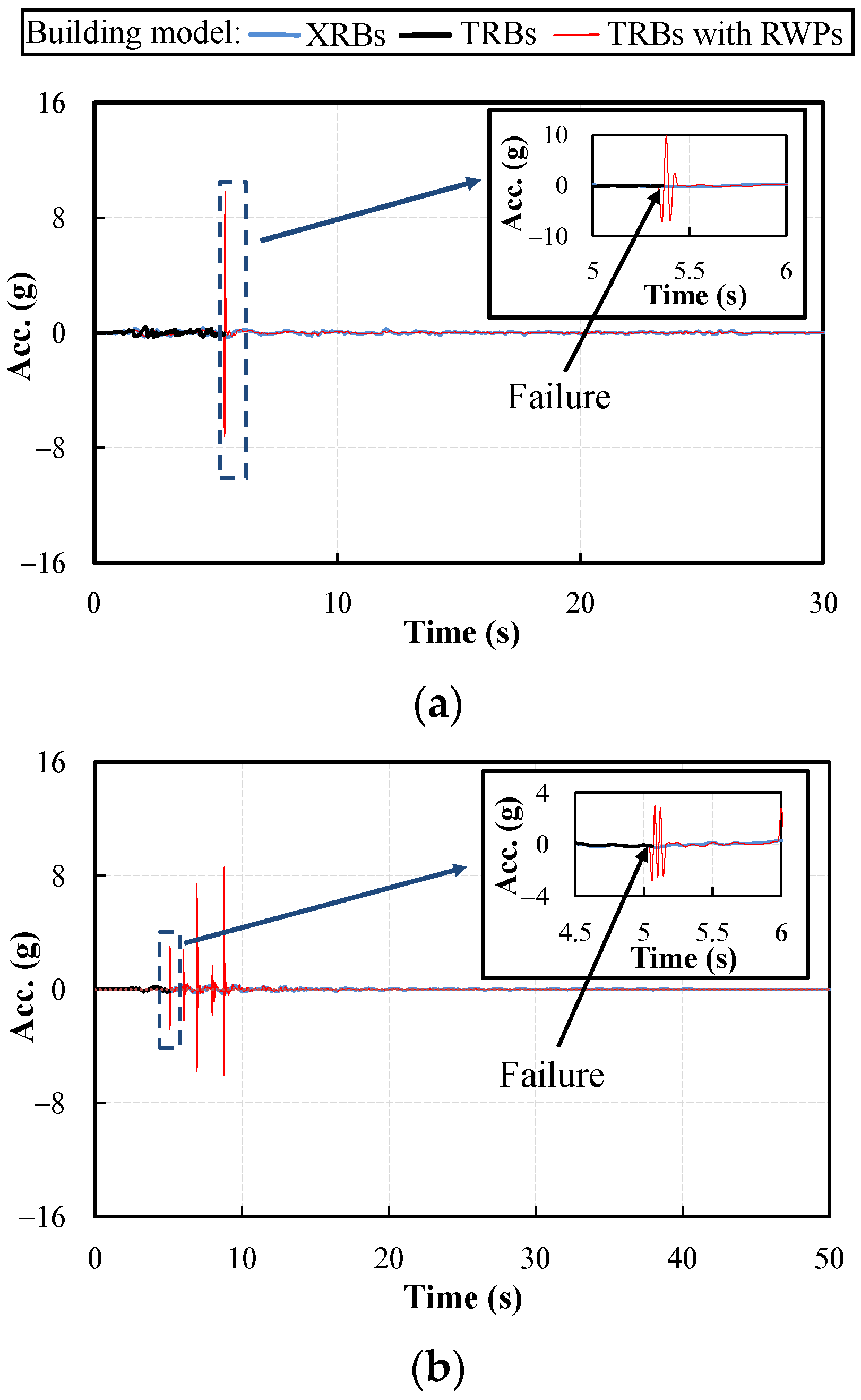
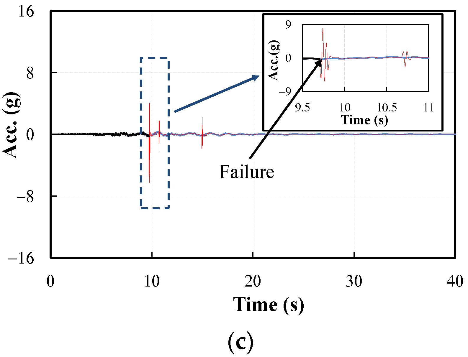
4.2.3. Acceleration Response

The acceleration response of the first floor of the building affects the seismic intensity of the input structure, and it is an important evaluation index of the seismic isolation performance of the building. Figure 10 and Figure 11 show the acceleration response of the first floor of different isolated buildings.
From the experimental acceleration response results, it is clear that the acceleration of the first floor of different isolated buildings is roughly the same under the ground motion at a 2–3% PE in 50 years. The maximum acceleration value of the first floor of the structure is about 0.2 g. However, with a PE of 1‱ ground motion in one year, there is a significant difference in the first floor acceleration of different isolated buildings. When the building uses TRBs with RWPs, the acceleration of the seismically isolated building produces a sudden and large increase. The maximum acceleration increases to 9.80 g, 8.61 g and 7.93 g for El Centro, Kobe, and Northridge seismic waves, respectively. For buildings using XRB, the acceleration of the superstructure decreases throughout the time history.

4.3. Discussion of Results

For the seismically isolated building with TRB, although the bearing deformation was less than the horizontal deformation limit (148.5 mm) under ground motion of 2–3% PE in 50 years, the maximum horizontal deformation exceeded the horizontal deformation limit under ground motion of 1‱ PE in one year, and caused the failure of the building isolation layer.
Under a 50-year 2–3% PE ground motion, the displacement, velocity, and acceleration response for a seismically isolated building using TRB with RWPs is the same as that for a seismically isolated building without RWPs. Under the ground motion of one year 1‱ PE, when the bearing displacement reaches 148.5 mm, although the RWPs can prevent the bearing from deformation failure, the structure will cause the acceleration change by impacting the RWP at high speed at this time. The peak acceleration at the first floor of the building reaches 13-16 times the input due to the effect of the impact between the building and the RWP.
The horizontal deformation limit of the seismically isolated building with XRB is greater than the horizontal shear deformation limit with TRB. The maximum horizontal deformation of the building with XRB is less than the horizontal deformation limit under one year and 1‱ PE ground motions. Therefore, XRB can still ensure that the seismically isolated building is in a safe condition when an extremely rare earthquake occurs. At this time, the transfer rates of the maximum vibration acceleration of the first floor of the building with XRB were 0.60, 0.56, and 0.56 under the ground motion of El Centro, Kobe, and Northridge, respectively, which indicated that the seismic acceleration response of the building structure could be effectively reduced with XRB.

5. Summary and Conclusions

By studying the design and structural characteristics of the XRB, the horizontal stiffness of the bearing is analyzed, and the isolation performance and failure protection capability of the bearing are explored. Based on the nonlinear time history analysis method, the displacement, velocity and acceleration responses of buildings using XRB, TRB, and TRB with RWP under different seismic levels are compared. The above research provides a new idea for failure protection and performance optimization of seismic isolation layer from the perspective of rubber bearing geometry construction. It also provides a meaningful reference for the design and practical application of this type of bearing. The mechanical properties of XRB and its optimization can be further studied by means of experiments and bearing geometry topology analyses in the future. The following conclusions can be drawn from above analyses.
(1)
The limit value of horizontal shear deformation of XRB is greater than that of TRB, which can effectively control the bearing failure under strong earthquake. XRB can effectively reduce the horizontal earthquake acceleration of the structure when the structure is subjected to a 2–3% PE earthquake with a 50-year event and a 1‱ PE earthquake with a one-year event, and has good horizontal seismic isolation performance, which can meet the need for horizontal isolation. At the same time, XRB can prevent the failure of the structure due to the over-limit deformation of the seismic isolation layer and improve the overall seismic safety of the isolated structure.
(2)
When the earthquake intensity exceeds the structural design ground motion intensity (for example, 1‱ PE in a one-year event), the horizontal displacement of the building will exceed the limit value of compressional shear deformation of TRB, leading to failure of the isolation layer and the collapse of the whole structure. Thus, it is necessary for the seismically isolated building to pay attention to the displacement of the isolation layer to avoid the displacement response of the earthquake exceeding the deformation limit value of TRB.
(3)
Although the RWP of the building can effectively prevent the deformation of the isolation layer from exceeding the limit, the superstructure will collide with the RWPs when the horizontal displacement of the isolation bearing reaches the limit displacement. When the superstructure possesses a large impulse, its collision with the RWP leads to a significant increase in collision damage and acceleration at the bottom of the superstructure. Therefore, when the bearing displacement exceeds the limit value, the seismic isolation structure with RWP can prevent the failure of the seismic isolation bearing, but it may lead to structural damage and may reduce the overall seismic isolation performance.

Author Contributions

Conceptualization, D.W. and Y.X.; methodology, D.W.; software, J.L.; validation, D.W., Y.X. and J.L.; formal analysis, J.L.; investigation, D.W.; resources, Y.X.; data curation, D.W.; writing—original draft preparation, J.L.; writing—review and editing, D.W.; visualization, Y.X.; supervision, Y.X.; project administration, Y.X.; funding acquisition, D.W. All authors have read and agreed to the published version of the manuscript.

Funding

This research was funded by [National Natural Science Foundation of China] grant number [52178281, 51778160, and 51878298], [Natural Science Foundation of Guangdong Province] grant number [2021A1515012606], [Guangdong Provincial Key Laboratory of Modern Civil Engineering Technology] grant number [2021B1212040003], and [Science and Technology Program of Guangzhou] grant number [201831826].

Institutional Review Board Statement

Not applicable.

Informed Consent Statement

Not applicable.

Data Availability Statement

The data presented in this study are available in this article.

Acknowledgments

The authors are thankful for the support from the National Natural Science Foundation of China (52178281, 51778160, and 51878298), the Natural Science Foundation of Guangdong Province (2021A1515012606), the Guangdong Provincial Key Laboratory of Modern Civil Engineering Technology (2021B1212040003), and the Science and Technology Program of Guangzhou (201831826).

Conflicts of Interest

The authors declare no conflict of interest.

References

  1. Bento, R.; Simões, A. Seismic Performance Assessment of Buildings. Buildings 2021, 11, 440. [Google Scholar] [CrossRef]
  2. Wu, D.; Tesfamariam, S.; Stiemer, S.F.; Cui, J. Comparison of seismic performance of a RC frame building before and after the Wenchuan earthquake in Sichuan province. J. Perform. Constr. Facil. 2015, 29, 04014038. [Google Scholar] [CrossRef]
  3. Vailati, M.; Monti, G.; Bianco, V. Integrated solution-base isolation and repositioning-for the seismic rehabilitation of a preserved strategic building. Buildings 2021, 11, 164. [Google Scholar] [CrossRef]
  4. Hur, M.W.; Park, T.W. Seismic Performance of Story-Added Type Buildings Remodeled with Story Seismic Isolation Systems. Buildings 2022, 12, 270. [Google Scholar] [CrossRef]
  5. Smith, K. Frank Lloyd Wright and the Imperial Hotel: A Postscript. Art Bull. 1985, 67, 296–310. [Google Scholar] [CrossRef]
  6. Martel, R.R. The effects of earthquakes on buildings with a flexible first story. Bull. Seismol. Soc. Am. 1929, 19, 167–178. [Google Scholar] [CrossRef]
  7. Green, N.B. Flexible first-story construction for earthquake resistance. Trans. Am. Soc. Civ. Eng. 1935, 100, 645–652. [Google Scholar] [CrossRef]
  8. Caspe, M.S. Earthquake isolation of multistory concrete structures. J. Proc. 1970, 67, 923–932. [Google Scholar]
  9. Nazin, V.V. Buildings on gravitational seismoisolation system in Sebastopol. In Sixth Symposium on Earthquake Engineering; University of Roorkee: Roorkee, India, 1978; pp. 356–368. [Google Scholar]
  10. Seigenthaler, R. Earthquake-proof building supporting structure with shock absorbing damping elements. Schweiz. Bauztg. 1970, 20, 211–219. [Google Scholar]
  11. Delfosse, G.C. Full earthquake protection through base isolation system. In Proceedings of the 7th World Conference on Earthquake Engineering Istanbul Turkey, Istanbul, Turkey, 8–13 September 1980. [Google Scholar]
  12. Tarics, A.G.; Way, D.; Kelly, J.M. The implementation of Base Isolation for the Foothill Communities Law and Justice Center; Report to the National Science Foundation and the County of San Bernardino; Reid and Tarics Associates: San Francisco, CA, USA, 1984. [Google Scholar]
  13. Robinson, W.H.; Tucker, A.G. A lead-rubber shear damper. Bull. N. Z. Soc. Earthq. Eng. 1977, 10, 151–153. [Google Scholar] [CrossRef]
  14. Derham, C.J.; Kelly, J.M.; Thomas, A.G. Nonlinear natural rubber bearings for seismic isolation. Nucl. Eng. Des. 1985, 84, 417–428. [Google Scholar] [CrossRef]
  15. Wu, D.; Tesfamariam, S.; Yan, X. FRP-laminated Rubber Isolator: Theoretical Study and Shake Table Test on Isolated Building. J. Earthq. Eng. 2022. Available online: https://www.tandfonline.com/eprint/C4FWV8BGTEPSYINIJGN3/full?target=10.1080/13632469.2022.2074914 (accessed on 19 May 2022). [CrossRef]
  16. Almansa, F.L.; Weng, D.; Li, T.; Alfarah, B. Suitability of seismic isolation for buildings founded on soft soil. Case study of a RC building in Shanghai. Buildings 2020, 10, 241. [Google Scholar] [CrossRef]
  17. Wu, Y.M.; Samali, B. Shake table testing of a base isolated model. Eng. Struct. 2002, 24, 1203–1215. [Google Scholar] [CrossRef]
  18. Takahashi, Y.; Hoshikuma, J.I. Damage to road bridges induced by ground motion in the 2011 Great East Japan Earthquake. J. JSCE 2013, 1, 398–410. [Google Scholar] [CrossRef] [Green Version]
  19. Li, Y.; Zong, Z.; Huang, X.; Xia, J.; Liu, L. Experimental study on mechanical properties of high damping rubber bearing model. In IOP Conference Series: Earth and Environmental Science. IOP Publ. 2017, 61, 012105. [Google Scholar]
  20. Montuori, G.M.; Mele, E.; Marrazzo, G.; Brandonisio, G.; De Luca, A. Stability issues and pressure–shear interaction in elastomeric bearings: The primary role of the secondary shape factor. Bull. Earthq. Eng. 2016, 14, 569–597. [Google Scholar] [CrossRef]
  21. Kurihara, M.; Nishimoto, K.; Shigeta, M.; Tachi, Y. A Study on Response during Large Deformation in a Seismic Isolation Systemof Nuclear Island Buildings. JSME Int. J. Ser. 3 Vib. Control Eng. Eng. Ind. 1990, 33, 404–411. [Google Scholar]
  22. Wu, D.; Lin, J.T.; Xiong, Y.; Cui, J. Influence of site conditions on seismic performance of isolated high-speed railroad bridges. Adv. Struct. Eng. 2022. [Google Scholar] [CrossRef]
  23. Li, H.; Xie, Y.; Gu, Y.; Tian, S.; Yuan, W.; DesRoches, R. Shake table tests of highway bridges installed with unbonded steel mesh reinforced rubber bearings. Eng. Struct. 2020, 206, 110124. [Google Scholar] [CrossRef]
  24. Wang, S.; Yuan, Y.; Tan, P.; Zhu, H.; Luo, K. Experimental study on mechanical properties of casting high-capacity polyurethane elastomeric bearings. Constr. Build. Mater. 2020, 265, 120725. [Google Scholar] [CrossRef]
  25. Choi, E.; Nam, T.H.; Cho, B.S. A new concept of isolation bearings for highway steel bridges using shape memory alloys. Can. J. Civ. Eng. 2005, 32, 957–967. [Google Scholar] [CrossRef]
  26. Du, H.; Wang, Y.; Han, M.; Ibarra, L.F. Experimental seismic performance of a base-isolated building with displacement limiters. Eng. Struct. 2021, 244, 112811. [Google Scholar] [CrossRef]
  27. Clark, P.W.; Aiken, I.D.; Kelly, J.M.; Higashino, M.; Krumme, R. Experimental and analytical studies of shape-memory alloy dampers for structural control. Smart Struct. Mater. 1995 Passiv. Damping SPIE 1995, 2445, 241–251. [Google Scholar]
  28. Desroches, R.; Delemont, M. Seismic retrofit of simply supported bridges using shape memory alloys. Eng. Struct. 2002, 24, 325–332. [Google Scholar] [CrossRef]
  29. Ismail, M.; Rodellar, J.; Pozo, F. An isolation device for near-fault ground motions. Struct. Control Health Monit. 2014, 21, 249–268. [Google Scholar] [CrossRef]
  30. Kelly, J.M.; Konstantinidis, D. Mechanics of Rubber Bearings for Seismic and Vibration Isolation; John Wiley & Sons,: Hoboken, NJ, USA, 2011. [Google Scholar]
  31. Takabayashi, K. Failure test of laminated rubber bearings with various shapes. In Proceedings of the World Conference on Earthquake Engineering, Madrid, Spain, 19–24 July 1992; Volume 1, p. 2277. [Google Scholar]
  32. Fujita, T.; Fujita, S.; Tazaki, S.; Yohshizawa, T.; Suzuki, S. Research, development and implement of rubber bearings for seismic isolation. JSME Int. J. Ser. III 1990, 33, 394–403. [Google Scholar]
  33. Wu, D.; Xiong, Y.; Zhou, F.L.; Cui, J.; Huo, W.G.; Jiang, G.P. Special Shaped Isolation Bearing with High Bearing Capacity. CN201520313147.6, 4 November 2015. (In Chinese). [Google Scholar]
  34. Koh, C.G.; Kelly, J.M. A simple mechanical model for elastomeric bearings used in base isolation. Int. J. Mech. Sci. 1988, 30, 933–943. [Google Scholar] [CrossRef]
  35. Wu, D.; Tesfamariam, S.; Stiemer, S.F.; Qin, D. Seismic fragility assessment of RC frame structure designed according to modern Chinese code for seismic design of buildings. Earthq. Eng. Eng. Vib. 2012, 11, 331–342. [Google Scholar] [CrossRef]
  36. National Standard of the People’s Republic of China (NSPRC). Seismic Ground Motion Parameters Zonation Map of China; China Standards Publishing House: Beijing, China, 2015. (In Chinese) [Google Scholar]
  37. National Standard of the People’s Republic of China (NSPRC). Code for Seismic Design of Buildings (GB50011-2010); Ministry of Construction of the People’s Republic of China: Beijing, China, 2010. (In Chinese)
  38. National Standard of the People’s Republic of China (NSPRC). In Code for Design of Concrete Structures (GB 50010-2010); Ministry of Construction of the People’s Republic of China: Beijing, China, 2010. (In Chinese)
  39. Park, R.; Kent, D.C.; Sampson, R.A. Reinforced concrete members with cyclic loading. J. Struct. Div. 1972, 98, 1341–1360. [Google Scholar] [CrossRef]
  40. Karsan, I.D.; Jirsa, J.O. Behavior of concrete under compressive loadings. J. Struct. Div. 1969, 95, 2543–2564. [Google Scholar] [CrossRef]
  41. Yassin, M.H.M. Nonlinear Analysis of Prestressed concrete Structures under Monotonic and Cyclic Loads. Ph.D. Dissertation, Department of Civil Engineering, University of California, Berkeley, CA, USA, 1994. [Google Scholar]
  42. Menegotto, M. Method of analysis for cyclically loaded RC plane frames including changes in geometry and non-elastic behavior of elements under combined normal force and bending. In Proceedings of the IABSE Symposium on Resistance and Ultimate Deformability of Structures Acted on by Well Defined Repeated Loads, Lisbon, Portugal, 1973; pp. 15–22. Available online: https://www.e-periodica.ch/digbib/view?pid=bse-re-001:1973:13::42#60 (accessed on 19 May 2022).
  43. Filippou, F.C.; Popov, E.P.; Bertero, V.V. Effects of Bond Deterioration on Hysteretic Behavior of Reinforced Concrete Joints; Report EERC 83-19; Earthquake Engineering Research Center, University of California: Berkeley, CA, USA, 1983. [Google Scholar]
  44. Mazzoni, S.; McKenna, F.; Scott, M.H.; Fenves, G.L. OpenSees Command Language Manual; Pacific Earthquake Engineering Research (PEER) Center: Berkeley, CA, USA, 2006; Volume 264, pp. 137–158. [Google Scholar]
Figure 1. (a) Three-dimensional appearance of XRB; (b) longitudinal section of XRB.
Buildings 12 01102 g001
Figure 2. Schematic diagram of isolated buildings using: (a) XRBs; (b) TRBs; (c) TRBs with RWPs.
Buildings 12 01102 g002
Figure 3. Horizontal force-displacement hysteresis model of: (a) A bearing, (b) a damper, (c) the combination of a bearing and damper.
Buildings 12 01102 g003
Figure 4. (a) Cross section of column; (b) beam.
Buildings 12 01102 g004
Figure 5. Earthquake acceleration (Acc.) time curve: (a) El Centro; (b) Kobe; (c) Northridge; and (d) Sa under different ground motions.
Buildings 12 01102 g005aBuildings 12 01102 g005b
Figure 6. Displacements of the 1st floor under the ground motions at a 2–3% PE in 50 years: (a) El Centro; (b) Kobe; (c) Northridge.
Buildings 12 01102 g006
Figure 7. Displacements of the 1st floor under the ground motions at a 1‱ PE in one year: (a) El Centro; (b) Kobe; (c) Northridge.
Buildings 12 01102 g007
Figure 8. Velocities of the 1st floor under the ground motions at a 2–3% PE in 50 years: (a) El Centro; (b) Kobe; (c) Northridge.
Buildings 12 01102 g008
Figure 9. Velocities of the 1st floor under the ground motions at a 1‱ PE in one year: (a) El Centro; (b) Kobe; (c) Northridge.
Buildings 12 01102 g009aBuildings 12 01102 g009b
Figure 10. Accelerations of the 1st floor under the ground motions at a 2–3% PE in 50 years: (a) El Centro; (b) Kobe; (c) Northridge.
Buildings 12 01102 g010aBuildings 12 01102 g010b
Figure 11. Accelerations of the 1st floor under the ground motions at a 1‱ PE in one year: (a) El Centro; (b) Kobe; (c) Northridge.
Buildings 12 01102 g011aBuildings 12 01102 g011b
Table 1. Characteristic parameters of the structural model.
ParameterValueUnit
Elastic modulus of concrete30,000Mpa
Axial compressive strength of concrete20.1Mpa
Elastic modulus of reinforcement200,000Mpa
Yield strength of reinforcement335Mpa
1st NP of model using XRBs1.80s
1st NP of model using TRBs1.96s
Publisher’s Note: MDPI stays neutral with regard to jurisdictional claims in published maps and institutional affiliations.

