Article

Vibration-Reduction Strategy for High-Rise Braced Frame Using Viscoelastic-Yielding Compounded BRB

1
Faculty of Infrastructure Engineering, Dalian University of Technology, Dalian 116024, China
2
College of Civil and Transportation Engineering, Hohai University, Nanjing 210098, China
*
Author to whom correspondence should be addressed.
Buildings 2022, 12(8), 1159; https://doi.org/10.3390/buildings12081159
Submission received: 20 June 2022 / Revised: 21 July 2022 / Accepted: 1 August 2022 / Published: 3 August 2022
(This article belongs to the Section Building Structures)

Abstract

:
A buckling-restrained brace (BRB) serves as a typical load-bearing and energy-dissipative device for the passive control of structures under seismic loading. A BRB is generally designed to not yield under frequently occurring earthquake (FOE) and wind loads, resulting in it having less effectiveness in vibration reduction compared with post-yielding performance. To address this dilemma, this study proposed the concept and technique details of the viscoelastic-yielding compounded BRB (VBRB). Different from a conventional BRB, a VBRB is fabricated by attaching the viscoelastic damper (VED) to the surface of a BRB’s steel casing, ensuring a compatible deformation pattern between the VED and the BRB’s steel core. A dynamic loading test of VBRB specimens was carried out in which 0.2 Hz~0.6 Hz in loading rate and a maximum of 550 kN in load-bearing capacity had been applied, verifying the feasibility and performance of the VBRB. Subsequently, a parametric design procedure was developed to determine the required VBRB parameters so that the maximum elastic drift response of the structure could be reduced to the code-prescriptive value. The wind-resistance and seismic performances of the VBRB were critically evaluated through dynamic time-history analyses on a 48-story mega VBRB-equipped frame designed according to the Chinese seismic design code (GB50011-2010), and the effectiveness of the approach was also verified. Results indicate that the VBRB has advantages over a conventional BRB by providing a multi-stage passive energy dissipation capacity, resulting in a better vibration-control effect than conventional BRBs for structures subjected to wind load and seismic excitations.

1. Introduction

Steel braces are a typical class of efficient seismic-force-resisting system widely used in earthquake engineering. The popularity of conventional braces is characterized by their light weight, easy installation and replacement, and efficiency in strengthening structures, as well as the insignificant adverse effect on the main structure during construction. However, the inherent deficiency of conventional braces is the buckling in compression, resulting in less energy dissipation during compression and asymmetrical hysteretic behavior in tension and compression [1]. To improve this inadequacy, a BRB was proposed by the researchers in which an external casing (a steel tube is often adopted) filled with mortar was employed to restrain the buckling of the steel core [2], and the steel core is the only element subjected to inelastic deformation. The steel core generally consists of three segments: yielding zone, transition zone, and connection zone. A gap is intentionally left between the mortar and steel core to ensure free axial deformation in the steel core [1]. Having a symmetrical hysteretic behavior, a BRB shows remarkable advantages over conventional braces in terms of load-bearing and energy-dissipation capacity. Conventional BRBs can be generally categorized into BRBs with concrete-filled tubes and all-steel BRBs [3]. Research on conventional BRBs has been systematically carried out, including on different types of steel cores [4,5,6,7], fatigue and reversed-cyclic properties [8,9], cumulative deformation capacity [10], major design parameters [11], etc. On account of the promising energy-dissipation capacity, BRBs are preferably regarded as dampers rather than braces in Japan [12].
The seismic performances of BRB-strengthened braced frames have also been extensively evaluated. For example, Mahrenholtz et al. experimentally examined the behavior of RC frames retrofitted with BRBs. Results indicated that a BRB increased the strength, ductility, and energy-dissipation efficiency of the frame. Qu et al. tested the single-bay RC frame strengthened with BRBs in double-K configuration. Sabelli et al. [13] investigated the seismic responses of three- and six-story BRB-strengthened braced frames with nonlinear dynamic analyses. Several seismic design approaches for BRB-strengthened braced frames were also developed, such as a displacement-based method [14] and an energy-based method [15]. In addition, a BRB-to-reinforced-concrete (RC) member connection is also a key construction to be researched, such as a novel BRB connection, proposed by Bai et al., [16] using shear connectors to connect gusset plates and RC components. In spite of the above-mentioned advantages of conventional BRBs, there are still deficiencies such as unavoidable residual deformation and a limited vibration-reduction effect for structures with small vibration magnitudes.
To address these issues, BRBs with functional improvements have been proposed, such as the self-centering BRB (SC-BRB), double-stage yield BRB (DY-BRB), hybrid BRB (H-BRB), etc. SC-BRB refers to the bracing system with self-centering capacity and flag-shaped hysteretic response so that residual deformation in the brace can be reduced. An SC-BRB primarily consists of tensioning elements and an energy-dissipation system. A number of devices have been used as tensioning elements in the SC-BRB to provide self-centering behavior, such as metallic tendons [17], shape memory alloy (SMA) rods [18,19], tendons made of composite polymer materials [20], disc springs [21,22], etc. A DY-BRB is designed to have two-stage yield behavior that consists of a large BRB and a smaller one. Results of nonlinear analysis reveal that a DY-BRB can effectively control the deformation pattern and prevent a weak-story collapse of the structure [23]. An H-BRB [24,25] is a composite damper system that combines BRBs and viscoelastic dampers. The viscoelastic damper is responsible for dissipating the energy caused by the load from weak earthquakes or wind. Note that since conventional BRBs cannot dissipate energy before yielding, the introduction of deformation-sensitive or velocity-sensitive material (i.e., viscoelastic material) to expand the effective energy-dissipation range of a BRB is feasible and promising. In this case, a BRB will enjoy better adaptivity to variable deformation magnitudes, resulting in an improved energy-dissipation capacity for the structures subjected to wind and seismic loads. Although an H-BRB was proposed and experimentally explored [25], the adaptivity of BRB-strengthened structures to wind-induced load and seismic loading, as well as the corresponding seismic design approach, still need to be scrutinized.
On the other hand, a great number of studies have been carried out on the vibration attenuation of structures using viscoelastic materials. This class of materials has time-dependent stress-strain relationships characterized by transient properties, such as creep and stress relaxation. There exists a phase angle between the stress and strain for the viscoelastic material, and the tangent of the phase angle is an effective measure of material damping [26]. There have been a variety of approaches to measure the responses of material viscoelasticity. Mechanical tests, in the form of tensile, bending, torsional, or other deformation modes, are most widely used by applying harmonic forces to the specimens via electromagnetic interaction or servo-controlled hydraulic system [26], and material parameters can be calculated through dynamic responses of the specimens [27], such as storage modulus, loss modulus, loss factor, etc. Creep tests and stress relaxation tests are also the conventional approaches to experimentally investigate material viscoelasticity in the time domain. In addition, a number of techniques and instruments for phase measurement in the frequency domain have been invented. For instance, the commercially available dynamic mechanical analyzer (DMA) can be applied to measure the viscoelastic properties of materials by considering varied temperature and excitation frequency. Resonant ultrasound spectroscopy (RUS) determines material properties from the sample resonant frequency [28], while broadband viscoelastic spectroscopy (BVS) can measure the viscoelastic behavior over a broader frequency range [29].
The typical application of viscoelastic material in structural engineering is to dissipate vibrational energy in structures with the use of a VED. A VED is usually made up of rubber sandwiched by the steel boards on both sides to accommodate the shear deformation in the viscoelastic layer. Tsai et al. [30] and Chang et al. [31] examined the mechanical properties of VED considering the effect of ambient temperature and frequency. Similarly, Bergman [32] investigated the influence of frequency, temperature, cumulative energy absorption, and displacement amplitude on VED performance. A number of mechanical models have been proposed to describe VED behavior, including the Kelvin model, Maxwell model, standard mechanical model (SMM) [33], equivalent standard solid model [34], etc. Besides, there was also plentiful research conducted on the seismic responses of VED-equipped structures, such as the shaking-table tests of VED-equipped structures conducted by Chang et al. [35,36].
Considering that VED is efficient in vibration reduction for structures at small drift magnitudes, this paper attempts to propose a whole-process vibration-reduction strategy for high-rise braced frames with the use of VBRBs. Different from an H-BRB [24], the BRB brace of a VBRB is surrounded by four full-length VED components, and an improved energy-dissipation capacity can thus be expected. The concept and construction details of a VBRB are elaborated at first. Subsequently, dynamic tests of VED specimens are introduced to validate their mechanical properties. After that, the seismic design approach is proposed to determine VED parameters applicable to high-rise braced frames. Finally, dynamic time-history analyses are carried out to evaluate the proposed approach and vibration reduction effect of VBRB for mega braced frames subjected to wind load and mild to severe ground motions.

2. Concept and Mechanical Properties of VBRB

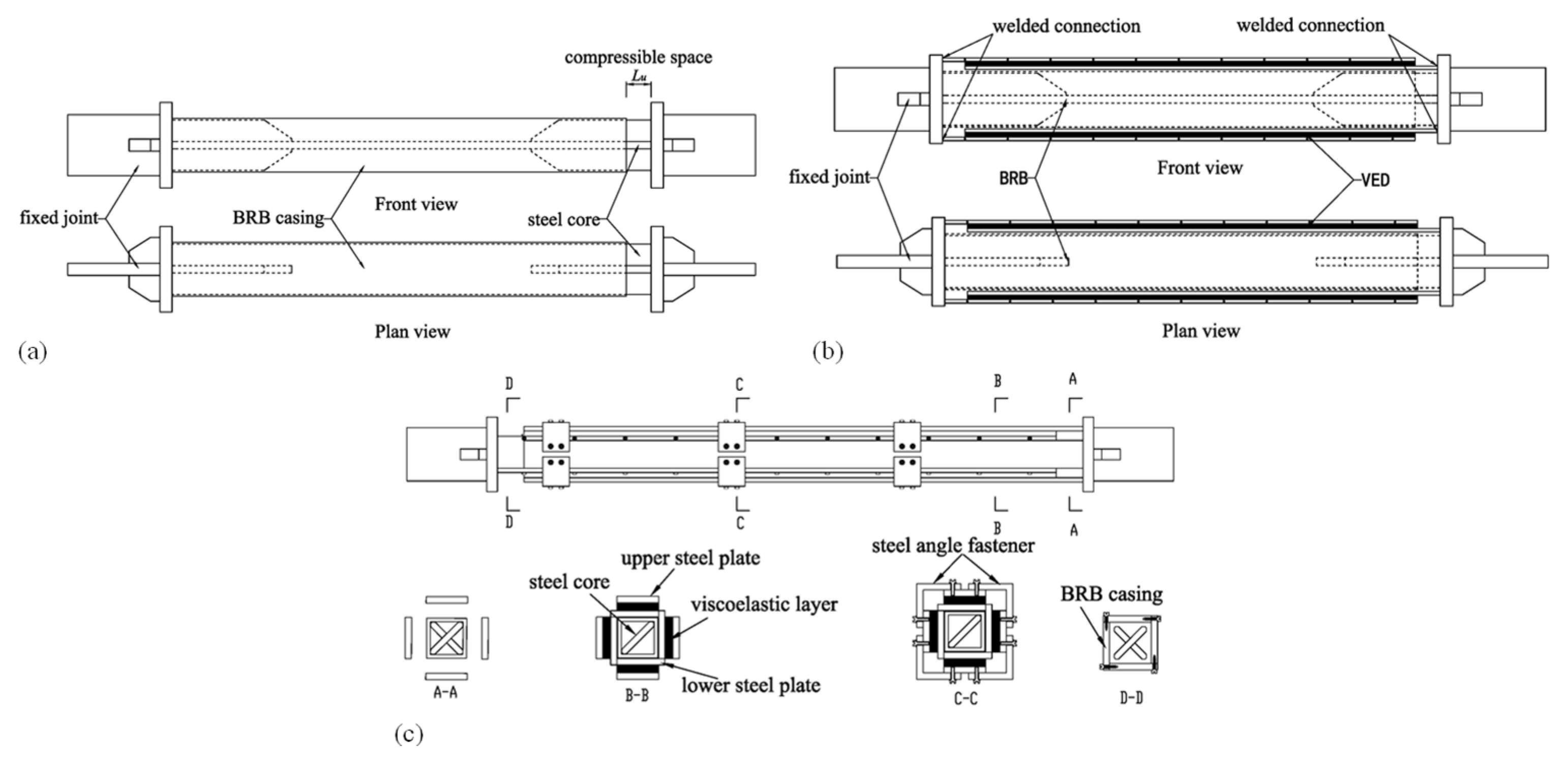
2.1. Concept and Detailing of VBRB

For typical displacement-dependent dissipators such as BRBs, seismic energy is dissipated through the development of inelastic deformation in the steel core. The force-deformation relationship of a BRB can be idealized using the bilinear model with the kinematic hardening rule. Generally, considerable energy dissipation can be expected in large-tonnage BRBs after the yielding of the steel core. In the event of structural lateral drift being not fully developed, however, a BRB becomes less effective in alleviating vibrational response. For instance, for structures subject to mild ground motions or wind loads, a BRB essentially increases structural lateral stiffness and hardly contributes to energy dissipation. Different from a BRB, a VED is a typical velocity-dependent dissipator. A VED starts to dissipate energy as long as the shear deformation appears at the viscoelastic layer and the damping force is related to material property, deformation rate, temperature, etc. For structures subjected to considerable lateral deformation, however, the damping force and absorbed energy are significantly less for a VED than for a BRB.
To make full use of the advantages of BRBs and VEDs, a VBRB is proposed by combining a VED with a BRB in parallel. Accordingly, the restoring force model for the VBRB can be viewed as the superposition of the BRB model and VED model. The schematic restoring force models of the BRB, VED, and VBRB at different deformation stages are illustrated in Figure 1a. For VBRB-equipped structures subjected to FOE or wind load (small deformation stage), a VED absorbs energy and provides additional damping for the structure, while the BRB remains linear-elastic and only adds elastic stiffness to the system. For the structures subjected to maximum-considered earthquake (MCE), a BRB gradually becomes the primary energy dissipation component after the yielding of the steel core. The advantage of a VBRB over a conventional BRB lies in two aspects: (1) the VBRB absorbs energy at small deformation stage due to the VED, while the BRB still remains linear elastic; and (2) the VBRB is expected to possess a larger energy-dissipation capacity than the conventional BRB at the large deformation stage (as illustrated by the VBRB hysteretic model in Figure 1a). The schematic of the proposed VBRB configuration is illustrated in Figure 1b. Featuring whole-process energy dissipation, the VBRB acts as a promising passive control apparatus to reduce the structural vibrations resulting from the wind loads and ground motions of varied intensities.

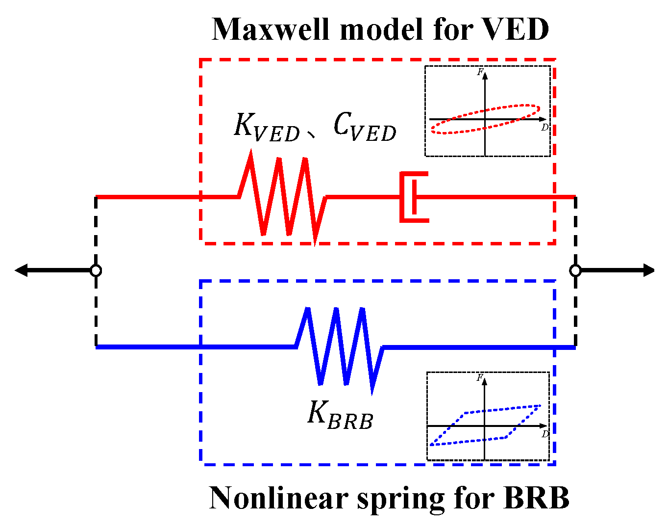
2.2. Mechanical Properties of VBRB

Suppose that a VED in a VBRB is subjected to harmonic excitation, and the shear deformation of the viscoelastic layer u can be described as:
u = u m a x sin ω t
The equivalent stiffness and damping coefficient of the VED can be described as:
K V E D = G A h
C V E D = G A ω h
where u m a x is the maximum shear deformation of the viscoelastic layer and ω is the excitation frequency. G and G represent the shear storage modulus and shear loss modulus of the viscoelastic material, respectively. A and h are the shear area and thickness of the viscoelastic material, respectively. G and G can be expressed as:
G = 1 1 + η 2 G
G = η 1 + η 2 G
where G and η denote the shear modulus and loss factor of the viscoelastic material, respectively. For a VED, the force output consists of elastic and viscous forces, i.e., F V E D K and F V E D C , and can be expressed as:
F V E D K = K V E D u m a x cos ω t
F V E D C = C V E D u m a x ω cos ω t
Substitute Equations (1)~(5) into Equations (6)~(16), let γ m a x = u m a x / h be the maximum shear strain, and the maximum values of F V E D K and F V E D C can be acquired as:
F V E D K , m a x = 1 1 + η 2 GA γ m a x
F V E D C , m a x = η 1 + η 2 GA γ m a x
Considering that the VED and BRB are connected in parallel, the stiffness of the VBRB, i.e., K V B R B , can be written as:
K V B R B = K V E D + K B R B
Note that K B R B is the elastic stiffness of the BRB. In the event of the yielding of the steel core, it is suggested that K B R B be equal to the secant stiffness, or that it can be calculated using the equivalent linearization method. Since the parameters of the BRB and VED are independent of each other, the force output ratio between the BRB and VED can be defined for the parametric design of VBRB, as shown in Equation (16).
F B R B | u = u m a x = λ F V E D | u = u m a x
where λ denotes the force output ratio between the BRB and VED when the target deformation of the VBRB is reached. Note that parameter λ actually defines a performance status of the VBRB by considering the yielding of the BRB. The bilinear hardening model is introduced to describe the BRB force-deformation relationship, and Equation (16) can be further rewritten as:
K B R B ( u y + α u m a x α u y ) = λ K V E D u m a x
where u y , K B R B , and α represent the yield displacement, elastic stiffness, and post-yield slope of BRB, respectively. Define the BRB displacement ductility μ , i.e., μ = u m a x / u y , and Equation (16) can be further simplified as:
K B R B K V E D = λ μ α ( μ 1 ) + 1
Equation (16) establishes the stiffness relationship between the BRB and the viscoelastic element, which can be used in the parametric design of the VBRB. To ensure enough energy dissipation in the BRB, λ is suggested to be larger than 3, resulting in K B R B being 10 times larger than K V E D . Consequently, the VED contributes significantly less stiffness compared with the BRB. The energy dissipated by the VED in a cycle can be estimated as:
W V E D , j = ( 2 π 2 / T 1 ) C V E D , j cos 2 θ j Δ u j 2
where T 1 is the fundamental period of the structure.   C V E D , j , θ j and Δ u j , are the damping coefficient, inclination angle, and shear deformation of the j th VED, respectively. Furthermore, the increase in structural lateral stiffness due to BRB can be calculated as:
K l a t e r a l = j = 1 n E A j L j cos 2 θ j
where E A j , L j , and θ j are the axial stiffness, length, and inclination angle of the j th BRB, respectively. To guarantee desirable low-cycle fatigue performance for the BRB, it is suggested that the ultimate strain in the steel core be not larger than 1.5%.

3. Dynamic Loading Test of VBRB Specimens

3.1. Construction of the VBRB Specimens

This section introduces the dynamic loading test of three VBRB specimens named as VBRB1~VBRB3. The intent of the test is to validate the performance of the VBRBs and examine the effect of loading rate. In VBRBs, conventional BRBs and VEDs are connected in parallel. The configuration and assemblage of VBRBs are shown in Figure 2. The assembly of a VBRB includes the assemblies of the BRB and VBRB. Steel BRBs, consisting of steel cores and square steel tube casings, are adopted herein and conventional assembly procedures can be followed to fabricate the BRB. As shown in Figure 2a, the steel core consists of a straight-shape energy-dissipation segment in the middle, cruciforms at both ends, and the transition segments connecting the middle plate and cruciforms. There is a gap between the steel core and the BRB casing to release the horizontal deformation of the steel core. The VED is fabricated by rendering a slice of high-damping rubber being sandwiched between the upper and lower steel plates with the use of hot vulcanization technology. High-damping rubber (PR04) produced by OVM Machinery Co., Ltd. is used as the viscoelastic material. The lower steel plates in each VED are bolted together to form a square steel tube covering the casing of the BRB. The left and right sides of the upper and lower steel plates are welded to the BRB end plates so that the viscoelastic component will undergo identical deformation as the steel core of the BRB (Figure 2b). To improve the integrity of the assemblage, three sets of steel angle fasteners are utilized to fasten the viscoelastic components with bolt connections, as shown in Figure 2c.
The design of VBRB specimens follows the mechanical properties as introduced in Section 2.2. The material for the BRB steel core is Q235B, while the material for the BRB casing and VED steel plates is Q345B. The material property of PR04 rubber was tested considering the variations of shear strain and loading rate, and the results are shown in Table 1. It can be seen that the shear modulus of PR04 decreases with the increase in shear strain, and the loading rate has insignificant effect on the shear modulus and loss factor. In other words, the viscoelastic material is adaptive to a wide range of structural response frequencies because of its frequency insensitivity attribute. The VBRB specimens are designed with a maximum of 2.38% axial strain in the BRB’s yielding core, which corresponds to a maximum of 200% shear strain in the VED. The three VBRB specimens were designed with identical parameters, as shown in Table 2.

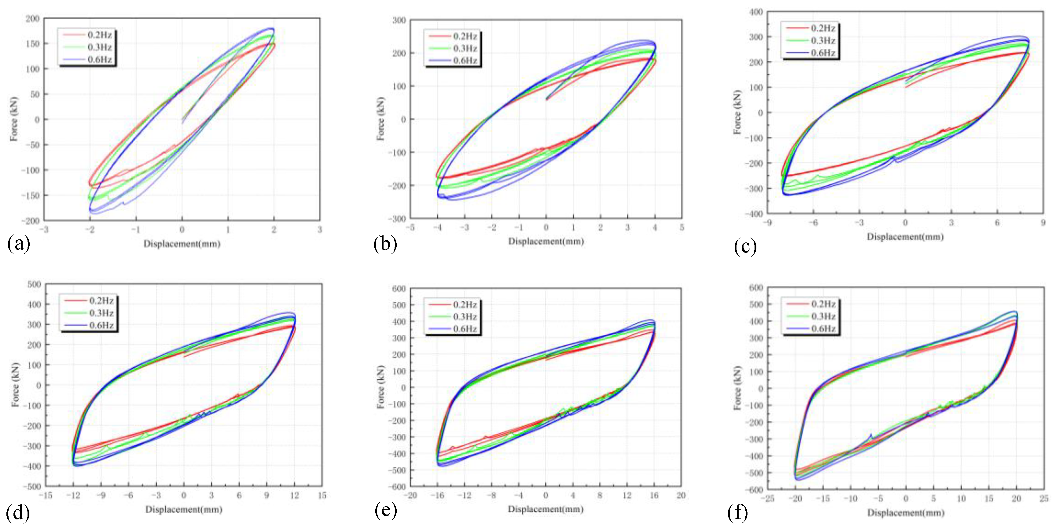
3.2. Dynamic Loading Test of VBRB

The VBRB specimens were loaded with a 2500kN MTS servo-controlled hydraulic actuator. Two-stage loading was adopted during the test. The loading protocols are shown in Table 3 and Figure 3b. Force-controlled sinusoidal loading (Step 1) was employed before the yielding of the BRB steel core, followed by the displacement-controlled sinusoidal loading as shown from Step 2 to Step 7. Twenty cycles were repeated in Step 1 and three cycles were repeated in the subsequent steps. The maximum loading magnitude was set as 200% of the shear strain in the VED to make full use of the viscoelastic material. VBRB1, VBRB2, and VBRB3 were loaded under the frequency of 0.2 Hz, 0.3 Hz, and 0.6 Hz, respectively. The loading instrument is shown in Figure 3a.

3.3. Analysis on the Test Results

The hysteresis curves of the VBRB specimens are depicted in each plot in Figure 4 by keeping the loading rate constant. There was an abrupt stiffness decrease at about γ V E D = 10 % , marking the yield of the BRB steel core. After that, a steady increase in the load bearing capacity was observed in the VBRB with the increment of displacement. Strong nonlinearity was observed in the hysteresis curves characterized by a decrease in secant stiffness. The plump hysteresis curves indicate a promising energy-dissipation capacity for the VBRB specimens. Additionally, it is noted that the peak loads in the positive and negative directions are not equal. This phenomenon is due to the compressive force in the BRB being larger than the tensive force when the identical target displacement is reached.
Replot the hysteresis curves in each figure by varying the loading rate and keeping the displacement identical, and the results are shown in Figure 5. Note that there is local jagged fluctuation at the compression side of the curve. It can be seen that the peak loads and absorbed energy for the VBRB specimens slightly increase with the increase in the loading rate. However, the discrepancy in energy dissipation resulting from the varied loading frequencies is negligible in the VBRB. Since the BRB belongs to the displacement-dependent energy dissipative device and absorbs the majority of the seismic energy at the large deformation stage, the influence of the VED on VBRB performance becomes insensitive to the loading rate. Testing results verified the feasibility of the proposed VBRB construction and supported the application in practical engineering because of its insensitivity toward the excitation frequency.

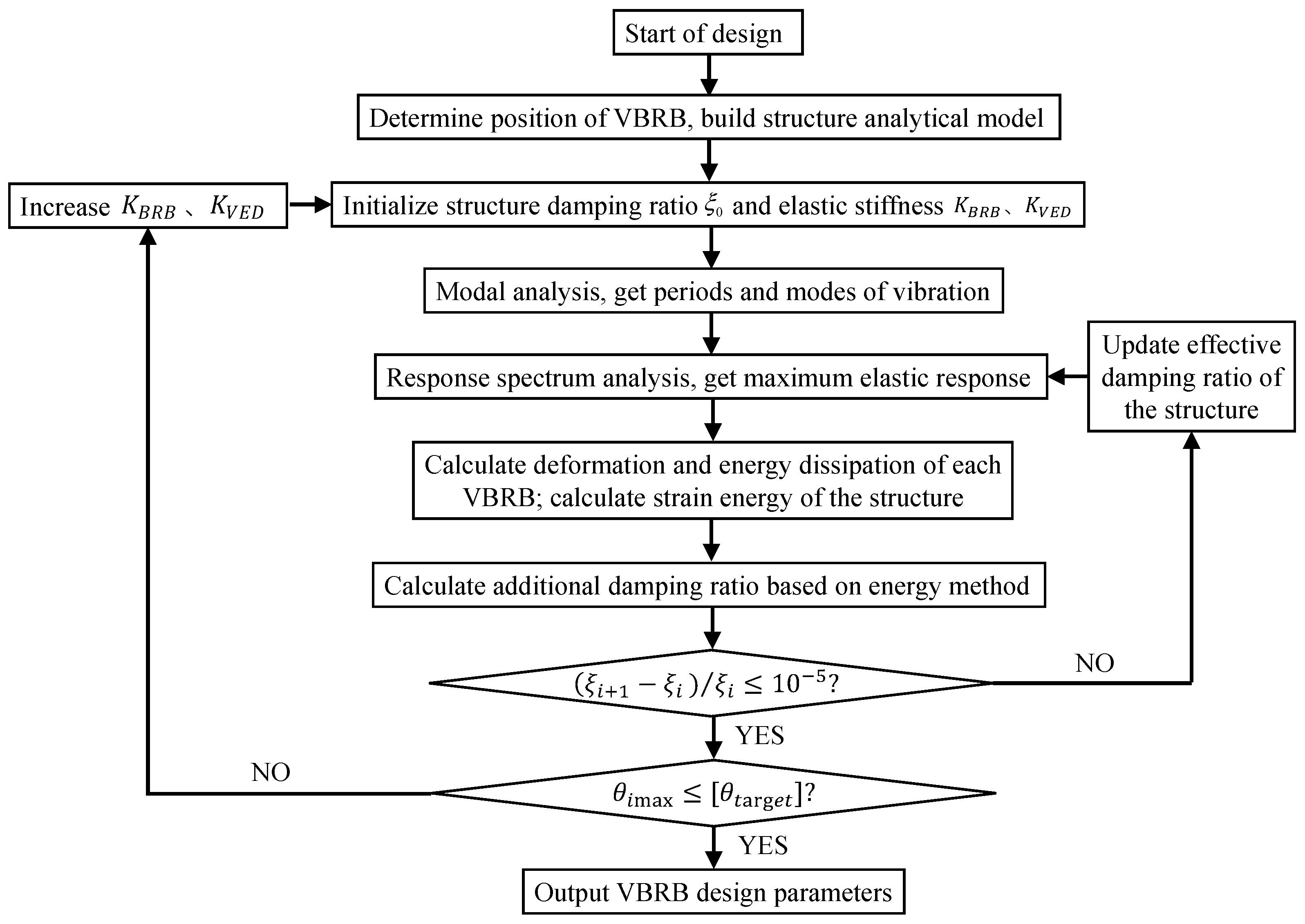
4. Parametric Design of VBRB for High-Rise Braced Frame

For the VBRB-equipped braced frame structure, the BRB primarily contributes lateral stiffness and the VED contributes energy dissipation under wind load and FOE. For structures subjected to MCE or even more severe ground motions, however, both the BRB and VED participate in energy dissipation and the BRB plays a leading role. The approach proposed in this section attempts to determine the design parameters of a VBRB (i.e., K V E D , C V E D , and K B R B ) so that the maximum elastic drift response of the structure can be reduced to the code-specified value.
The essence of the method is to determine the additional damping ratio resulting from the VED under FOE. The design parameters should be assumed in advance and iteration is needed to modify the design. The approach merely yields the lower limit of VBRB parameters for preliminary design. A deformation check of the structure subjected to more severe ground motions is required through time-history analysis, and modification may be required to get the ultimate design parameters. The step-by-step parametric design procedures of the approach are introduced below, and the design flow chart is shown in Figure 6.
Step 1. Select the maximum design lateral drift as code prescribed. Lay out the vibration reduction strategy for the structure, including the distribution and position of the VBRB. Establish the elastic finite element (FE) model of the structure in which the VBRB is modeled with an elastic truss element.
Step 2. Assign the initial elastic stiffness for the BRB (i.e., K B R B ) and calculate K V E D according to Equation (13). The elastic stiffness of the VBRB ( K V B R B ) is then calculated according to Equation (10). Modify the FE model by setting the stiffness of the VBRB element as equal to K V B R B .
Step 3. Perform a structural modal analysis to acquire periods and modes of vibration information.
Step 4. Calculate the maximum elastic drift response using the mode-superposition response spectrum method. Either the code-prescribed design acceleration spectrum or the average acceleration spectrum of a set of appropriate ground motions can be employed to perform the analysis. The number of modes included in the analysis should result in the sum of modal participation mass being no less than 90% of the structure mass. Note that the response spectrum of a specific ground motion is created by depicting the maximum responses of a damped single-degree-of-freedom (SDOF) system with respect to the varied periods, and the maximum responses (acceleration, relative velocity, or relative displacement) can be determined through time-history analyses using the numerical integration methods. The design spectrum can be finally acquired through the smoothing processing of a large amount of ground motion spectra with specific site conditions.
Step 5. Calculate the absorbed seismic energy in each VED ( W V E D , j ) with the use of Equation (14). Calculate the expected total strain energy W s for the structure reaching the target lateral drift.
Step 6. Calculate the effective additional damping ratio provided by the VBRB using the energy method, as shown in Equation (16), and the total damping ratio of the system at current step can be subsequently acquired.
ξ e = j = 1 n W V E D , j / ( 4 π W s )
Step 7. Calculate the relative error of the effective additional damping ratio between the two adjacent iterations. If the error is smaller than the specified limit, continue to the next step; otherwise, update the effective damping ratio with the value in the current iteration and repeat from Step 3 to Step 7 until the relative error requirement is satisfied.
Step 8. Judge whether the maximum inter-story drift ratio in the current step is no larger than the code-specified value. If so, output the BRB parameters; otherwise, increase K B R B and K V B R B (satisfying Equation (13)) and repeat from Step 2 to Step 8 until the above-mentioned criteria is satisfied.
Step 9. Determine the geometric parameters of the VED. End of the design.

5. Performance Assessment of VBRB-Equipped Braced Frame under Seismic Loadings

This section focuses on a case study in which VBRBs are applied to a 48-story mega braced frame as the energy-dissipation and vibration-reduction scheme. The approach developed in Section 4 will be introduced to determine the design parameters of the VBRB. Note that there are two braced frames considered in the case study in which conventional BRBs and VBRBs are adopted as the braces in the structure, respectively. The nonlinear FE models of the two structures were developed using the OpenSees program [37]. The effectiveness of the proposed method was discussed and the performances of the two structures were compared via dynamic time-history analyses. Note that the comparative analysis is intended to illustrate the advantage of the VBRB over the conventional BRB, especially in terms of moderate structural vibration reduction, rather than over other multi-functional composite BRBs. Consequently, the BRB parameters were identical in the two structures, and the only discrepancy between the conventional BRB and VBRB in the case study lies in the addition of VED components in the VBRB.

5.1. Basic Information of the High-Rise Mega Braced Frame

The code-compliant high-rise mega braced frame adopted in the case study was designed by Kang [38], which was a 48-story steel structure with a story height of 4 m and an overall height of 192 m. The structure has five spans in each direction with a column spacing of 8 m. There are four mega columns located at the corner of the building plane and three mega girders located at 19–20 story, 36–37 story, and 48 story, respectively. Plan layout and the elevation of the structure are shown in Figure 7a,b. The braced frame was designed considering the frequency-occurring earthquake of Intensity 8 (0.2 g) with Class Ⅱ site and Design Earthquake Group 1, according to the seismic design code [39]. The floor dead and live loads are 3.32   kN / m 2 and 2   kN / m 2 , respectively. Take the reference wind pressure as 0.45   kN / m 2 and shape factor of 1.3 for wind load. Q345 steel is applied to the columns between 1–24 stories, while Q235 steel is applied to the other structural members. The braces are mounted at standard layers, as well as in mega girders. The mega girders are fabricated using welded I-shaped steel, while the frame beams and cross beams in mega columns are fabricated using hot-rolled H-shaped steel. The columns in the structure have varied box sections. Details of the sectional information are listed in Table 4. The braced frames equipped with conventional BRBs and VBRBs are referred to as BRB-BF and VBRB-BF, respectively.

5.2. Design of VBRB and Analytical Model of the Structure

The parameters for VBRBs in VBRB-BF can be obtained by following the procedures as illustrated in Section 4. The target lateral drift ratio was set as 1/500 and the VBRB was designed to yield at a drift ratio of 1/350. For the viscoelastic material, a larger loss factor η will result in a higher additional damping ratio, and thus more effective vibration control effect for the structures under mild ground motions can be expected. The viscoelastic material (i.e., rubber) was preselected and the parameters are shown in Table 5. The value of λ = 3 was predetermined, and the effective damping ratio of 0.03 was used in the response spectrum analysis. By running the parametric analysis, convergence was quickly achieved and the design results are summarized in Table 6. Note that the update of the elastic FE model with increased K V B R B in Step 2 (Section 4) was achieved by enlarging the cross-sections of the VBRB elements. It can be seen that the VBRB adds approximately 1.5% of the effective damping ratio to the structure under FOE, which will be effective to alleviate the structural vibrational responses. According to the mechanical parameters (Table 6), the geometric parameters and the type of BRB brace and rubber can be further designated, and results are shown in Table 7. The cruciform steel core and square steel tube casing were selected to fabricate the BRB brace. The casing was surrounded by four pieces of full-length rubber layer serving as the VED components.
The three-dimensional nonlinear FE model of the structure was further established on the OpenSees structural analysis platform. All the beams and columns were modeled with the displacement-based beam-column elements with five Gauss–Lobatto integration points. Steel02 material was used to define the steel fiber sections. A conventional BRB was modeled with a truss element. The dynamic model of the VBRB is shown in Figure 8. In the model, the BRB and VED are connected in parallel. The VED was defined using the ViscousDamper material, which was based on the Maxwell model (linear spring and dashpot in series). The BRB was idealized with a nonlinear spring (link element), and Steel02 material was employed to define the element. Both the VED and BRB were modeled with truss elements that were arranged in parallel by setting common nodes. The VBRB mechanical parameters in Table 6 were input to establish the numerical model. Besides, a rigid diaphragm assumption was adopted during the analysis for calculation simplicity. The schematic of the nonlinear FE model is shown in Figure 7c. The model parameters were kept identical between BBR-BF and VBRB-BF, except for the different braces used in the structures.

5.3. Seismic Responses of BRB-BF and VBRB-BF under FOEs

A set of ground motions were selected as the input for elastic time-history analysis, including three natural waves and one artificial wave. The ground motions were scaled to have the same peak ground acceleration (PGA) of 70 cm/s2. The acceleration time histories are shown in Figure 9. Elastic time-history analyses were carried out and comparisons were made between the seismic responses of BRB-BF and VBRB-BF. The equivalent damping ratio used in the analysis was ξ = 0.03 for high-rise steel structures. The responses of the maximum drift ratio are compared in Figure 10. It can be seen that the lateral drift response over the height of the VBRB-BF is generally smaller than that of the BRB-BF except for in the Imperial Valley case. This phenomenon can be attributed to the function of the VED in a VBRB to absorb seismic energy and thus reduce vibrational responses for structures subjected to FOEs. Although the averaged maximum drift response of VBRB-BF is slightly larger than the design target, as shown in Figure 10e, the proposed parametric design procedure is generally effective in acquiring the VBRB parameters during the preliminary design. The discrepancy between the design value and numerical response is probably due to the seismic influence coefficient used in response spectrum analysis being not sensitive to long periods. The procedures based on response spectrum analysis are prone to yield unconservative story shear-force estimations, especially for long-period structures. Therefore, the design value of the inter-story shear forces used in the response spectrum analysis is advised to be modified according to the shear-gravity ratio, and time-history analysis should be included as a supplementary tool to result in a safe design.
The energy analysis was further carried out to investigate the energy composition of the structures during the seismic event. The time histories of the seismic energy distribution for VBRB-BF and BRB-BF are shown in Figure 11a,c, respectively. Note that only the response from the Imperial Valley-06 ground motion was taken here as an example. The seismic input energy is composed of three parts: energy dissipated by the equivalent viscous damping of the structure, energy dissipated by the structural components (including beams, columns, and braces), and kinetic energy. It is evident that the majority of the input energy is consumed by the equivalent viscous damping under FOE. The ratio of energy absorbed by the structural components for BRB-BF is approximately 30% of that for VBRB-BF, indicating that the VED in the VBRB has participated in dissipating seismic energy.
The energy dissipated by the structural components was further subdivided into the energy absorbed by the steel frame and the brace. Results are compared by resorting to Figure 11b,d. It is interesting to notice that the elastic strain energy stored in the frame beams, columns, and BRBs only oscillated and returned to zero at the end of the ground motion. For VBRB-BF, the VED in the VBRB is the only module that absorbed the seismic energy while keeping the other elements elastic. The energy dissipation ratio of the braces is further summarized as shown in Figure 12. It is obvious to notice that the BRB in the VBRB stores comparable elastic strain energy as conventional BRBs, while the VED in the VBRB dissipates 8%–10% of the seismic energy under FOEs. On account of the VED contribution, better drift response reduction can be expected in VBRB-BF compared with BRB-BF.

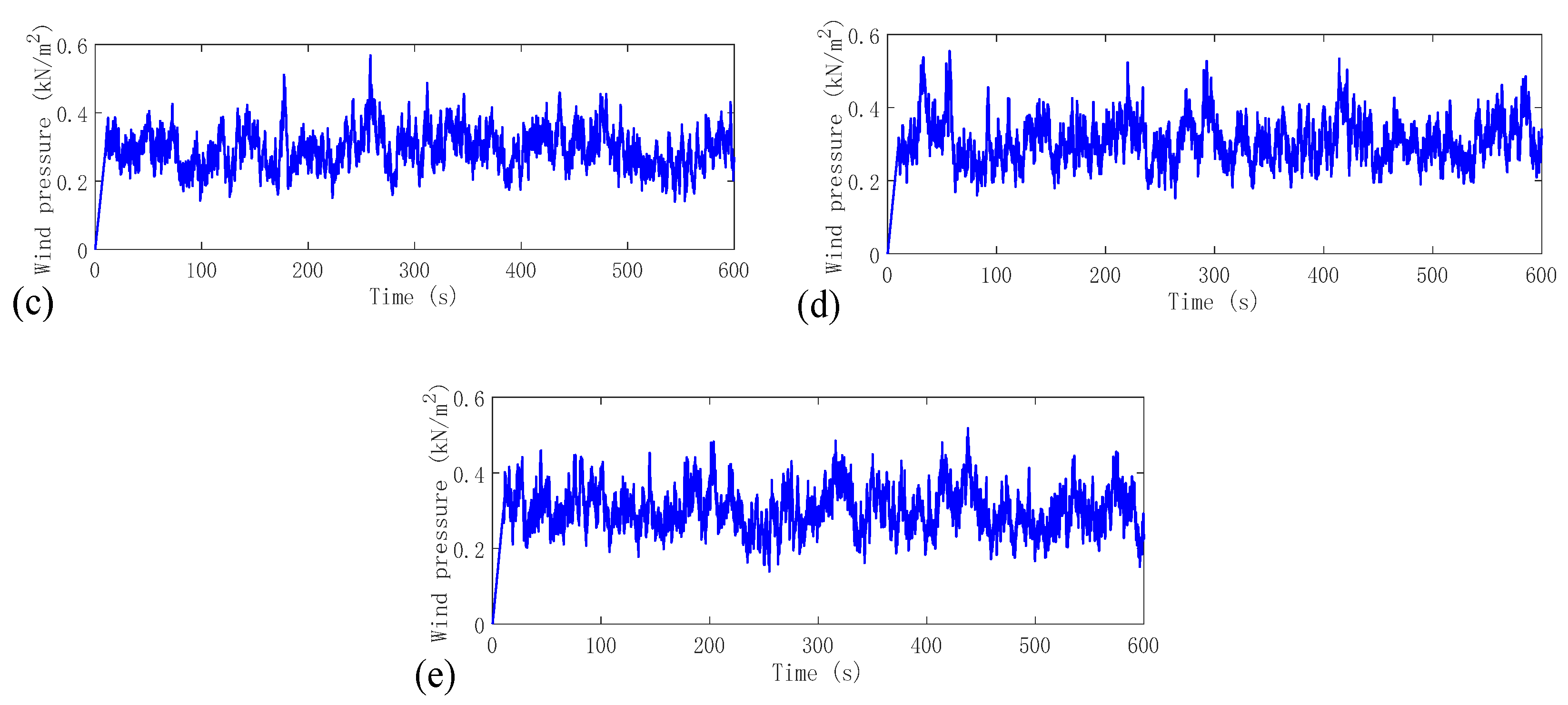
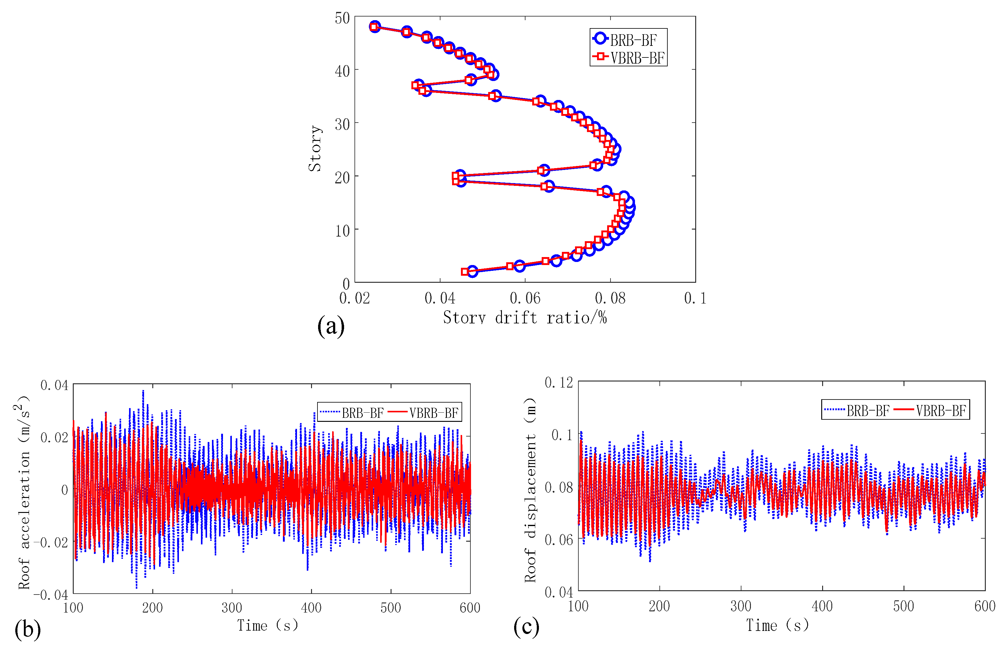
5.4. Seismic Responses of BRB-BF and VBRB-BF under Severe Ground Motions

In this section, the inelastic behavior of the mega braced frames subjected to MCE (earthquakes with 2% probability of exceedance in 50 years) and a super rarely occurring earthquake (SRE) are to be further evaluated. The SRE herein is defined as the ground motion whose seismic fortification intensity is one degree higher than that of the MCE. According to the seismic design code [39], the PGAs of MCE and SRE are 400 cm/s2 and 620 cm/s2 for the Intensity 8 seismic region, respectively. The same set of ground motions was scaled via PGA and used as the input of nonlinear time-history analyses.
The distributions of the maximum lateral drifts under the four ground motions are extracted and averaged, and the values are shown in Figure 13. In the figure, blue and red dots represent the drift of BRB-BF and VBRB-BF, respectively. The maximum drift stays no larger than 1/50 in both the MCE and SRE cases, falling into the allowable limit range as code stipulated. In addition, the inter-story drift distribution of VBRB-BF is similar to that of BRB-BF in both cases. Specifically, the drifts at the upper stories of VBRB-BF are slightly larger than those of BRB-BF, while at the lower stories of VBRB-BF they are slightly smaller than those of BRB-BF. BRBs serve as the primary energy dissipation devices for structures at the nonlinear stage. Since the BRBs in VBRB-BF and BRB-BF enjoy identical design parameters, similar seismic responses can be expected in the two systems.
Analysis of the energy distribution of the structures at the nonlinear state is further conducted, and the results of the MCE and SRE cases are illustrated in Figure 14 and Figure 15, respectively (only showing the Loma Prieta seismic wave). It is noticed that the structural components dissipate more than 50% of the seismic energy in the MCE case, and the ratio continues to increase in the SRE case. By further examining the component-dissipated energy, it is discovered that a conventional BRB in BRB-BF consumes comparable seismic energy as a VBRB in VBRB-BF and, consequently, steel frames dissipate similar amounts of energy in both cases. In the VBRB, the BRB modules consumed significantly larger seismic energy than the VED, proving that the BRB became the primary energy dissipator for structures subjected to MCE and SRE.
The above-mentioned conclusions can be firmly demonstrated by analyzing the energy dissipation ratio of the braces in both the MCE and SRE cases, and the results are shown in Figure 16. According to the figure, a larger amount of seismic energy was dissipated by the BRB in the SRE case than in the MCE case. Sufficient plastic deformation has developed in conventional BRBs and VBRBs under severe ground motions. The energy dissipated by the VED in a VBRB amounts to no more than 5% in both the MCE and SRE cases. In addition, the BRB in a VBRB absorbs slightly less seismic energy than the conventional BRB, as shown in the figure, and this may in turn result in a better low-cycle fatigue performance for the VBRB.

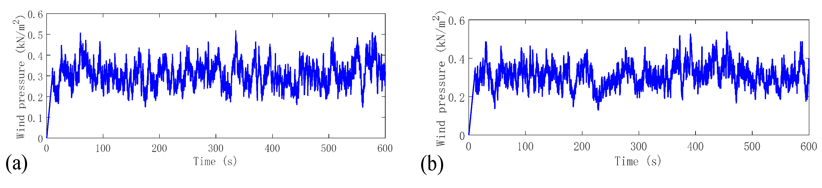
6. Performance Evaluation of VBRB-Equipped Braced Frame under Wind Loads

This section investigates the wind vibration control effect of a VBRB. For structures subjected to wind loads, a VBRB is expected to alleviate the vibrational response by providing additional viscous damping to the structure. Both VBRB-BF and BRB-BF were designed to locate at the site with a B-class surface roughness. The reference wind pressure for a 10-year return period is 0.3kN/m2. In wind resistance analysis, the fluctuating wind can be regarded as an ergodic stationary random process. In this section, the linear filter method based on an auto-regressive (AR) model was employed to generate the wind velocity time histories.
There are five sets of wind velocity time histories generated and are named Wind 01~Wind 05. Each wind velocity time history lasts 600 s with a time interval of 0.1 s. Since the wind velocity is relevant to the height of the application point, the wind load input used in the analysis should consider the variation of height. Suppose that a wind load is applied at each floor and roof level during the analysis. Therefore, each set actually contains 48 wind velocity time histories over the height of the structure (because VBRB-BF and BRB-BF have 48 stories). Subsequently, the wind velocity time histories were transformed into wind pressure time histories. The generated wind pressure time histories at the top of first floor are given in Figure 17 as an example. Finally, the wind load time histories can be acquired by multiplying the wind pressure at each story by the affiliated windward area of that story. The wind load time histories at each story are input as nodal loads and dynamic analyses can be carried out.
The wind-induced responses of VBRB-BF and BRB-BF are compared in Figure 18. The average lateral drift distribution of the two structures is shown in Figure 18a. It is obvious that the inter-story drifts of VBRB-BF are generally smaller than those of BRB-BF, which indicates the effectiveness of VEDs in reducing wind-induced vibration. The average responses of roof acceleration and roof displacement time histories are compared in Figure 18b,c, respectively. Compared with BRB-BF, both acceleration and displacement time histories of VBRB-BF are basically observed with minor magnitudes throughout the entire process. This phenomenon confirms that a VBRB has the advantage over a conventional BRB in alleviating the wind-induced dynamic response of the structure. In a VBRB, the VED can be regarded as a supplemental apparatus to enhance the energy-dissipation capacity of a BRB at the small deformation stage.
The maximum acceleration responses of VBRB-BF and BRB-BF are summarized in Table 8. It is essential to notice that the VBRB is prone to result in a lower value of root mean square of the acceleration response, compared with the conventional BRB. This may be due to the VBRB improving the system’s effective damping ratio during wind-induced vibration, and it thus reduces the magnitude of the structural dynamics response. By referring to Table 8 and Figure 18, it can be deduced that a VBRB is not only efficient in reducing the structural response magnitude, but also conducive to weakening the response fluctuation, and the latter will especially be useful in improving structural comforting conditions.
Energy analysis is further performed to quantify the energy variation tendency of structures subjected to wind loads. Similarly, the constitutions of input energy and energy absorbed by the structural components are analyzed. The result of the Wind 01 case is illustrated as an example and shown in Figure 19. Obviously, the wind-induced input energy is primarily dissipated by the structural components and the system-equivalent viscous damping. The amount of energy dissipated by the structural components in VBRB-BF is larger than that in BRB-BF. The VED dissipated approximately 17% of the input energy in the Wind 01 case. There is an oscillation characteristic observed in the energy dissipated by structural components, indicating that it is mainly elastic strain energy stored in the structural members. By comparing Figure 19b,d, it can be seen that the VED in the VBRB is the only element that provides stable energy dissipation, while the BRB and steel frame remain elastic under the function of wind load.
The additional damping ratio from the VBRB for all the calculation cases is summarized in Table 9. It is noticed that a VBRB will provide 1~2% of the additional damping ratio for the structures subjected to wind loads through energy dissipation in the VED. The amount of the additional damping ratio is quite effective in reducing wind-induced structural vibrations. Compared with conventional BRBs, a VBRB endows the structures with wind and seismic resistance characterized by passive energy dissipation. Note that since the sample mega braced frame is conservatively designed with adequate lateral stiffness, the wind-induced inter-story drift and thus the energy dissipation ratio of the VBRB are insignificant. The effectiveness of wind-induced vibration reduction can be further improved by fabricating the VED component with a viscoelastic material of larger loss factor.

7. Conclusions

This paper attempts to investigate a new vibration-reduction strategy for high-rise braced frames by proposing a VBRB device. The VBRB is fabricated by combining a conventional BRB and VED in parallel, resulting in multi-stage passive energy dissipation and vibration-reduction capacity. For structures subjected to wind load or FOE, the VED in a VBRB participates in energy dissipation and provides a viscous damping ratio to the system, while the BRB remains linear elastic and adds lateral stiffness to the system; for structures subjected to MCE or even more severe ground motions, a BRB becomes the primary energy dissipation device after the yielding of the steel core. The mechanism and construction of VBRBs was introduced at first. A dynamic loading test of three VBRB specimens was carried out to investigate the influence of loading rate on VBRB hysteretic performance. Then, a parametric design procedure was proposed to determine the VBRB parameters so that the maximum elastic drift response of the structure can be reduced to the code-specified value. Subsequently, a case study was carried out through systematically evaluating the performances of 48-story VBRB-BF and BRB-BF under wind loads and seismic loading, and the proposed parametric design procedure was also validated. The following primary conclusions can be reached from this research:
(1)
The proposed VBRB construction is feasible. Results of dynamic loading test indicate that a VBRB has a desirable energy-dissipation capacity characterized by a plump hysteresis curve. The load-bearing capacity of a VBRB increases with the increment of loading displacement, while the effect of loading rate on VBRB hysteretic behavior is insignificant. A maximum of 200% in shear strain was achieved in a VED during the test, corresponding to the maximum of 2.38% in axial strain in a BRB.
(2)
The case study reveals that the proposed parametric design procedure is basically effective in determining VBRB parameters during the preliminary design. The error of the approach may be due to the seismic influence coefficient used in response spectrum analysis being not sensitive to the long period. Modification of the parameters is advised and time-history analysis should be included as a supplementary tool to result in a safer design.
(3)
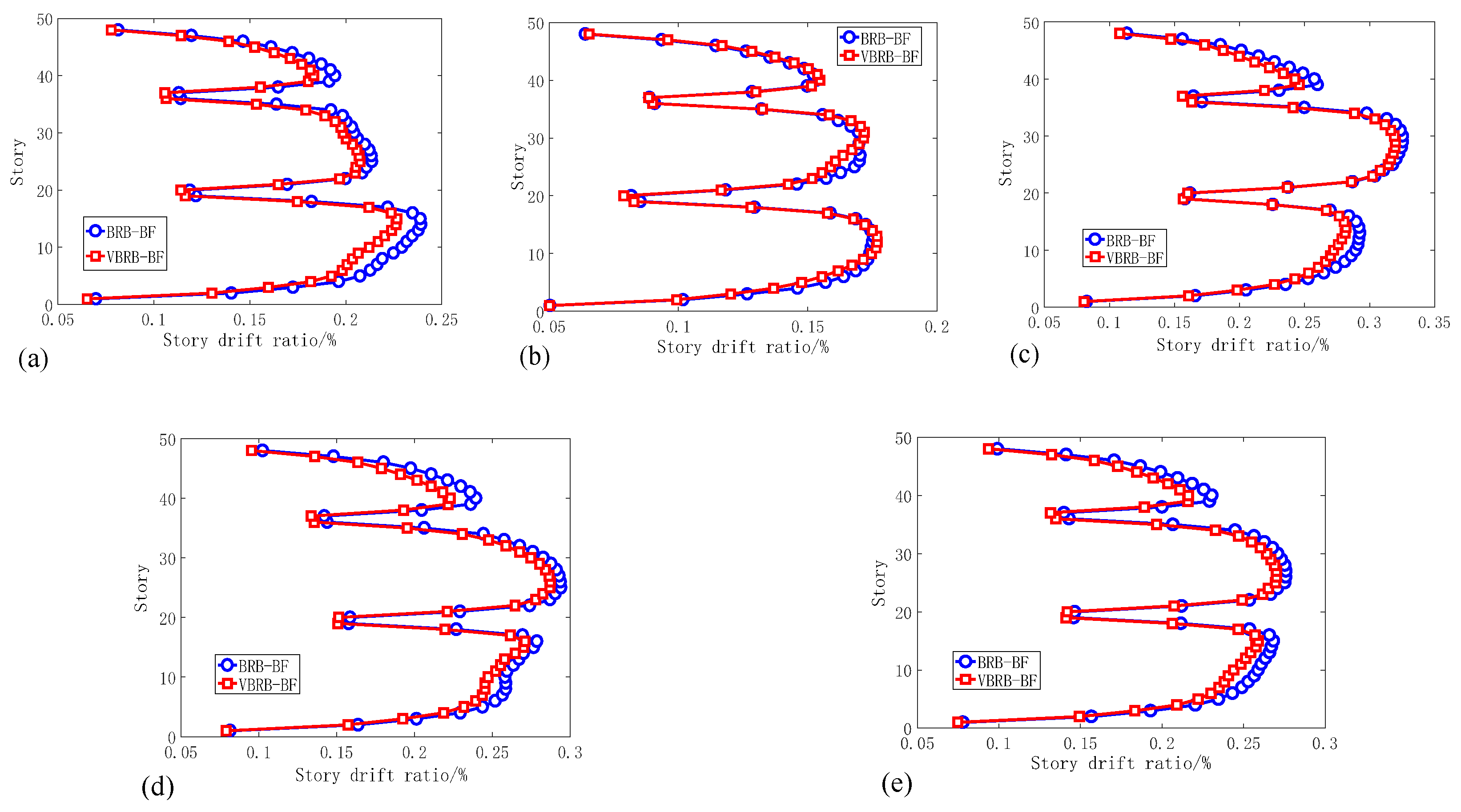
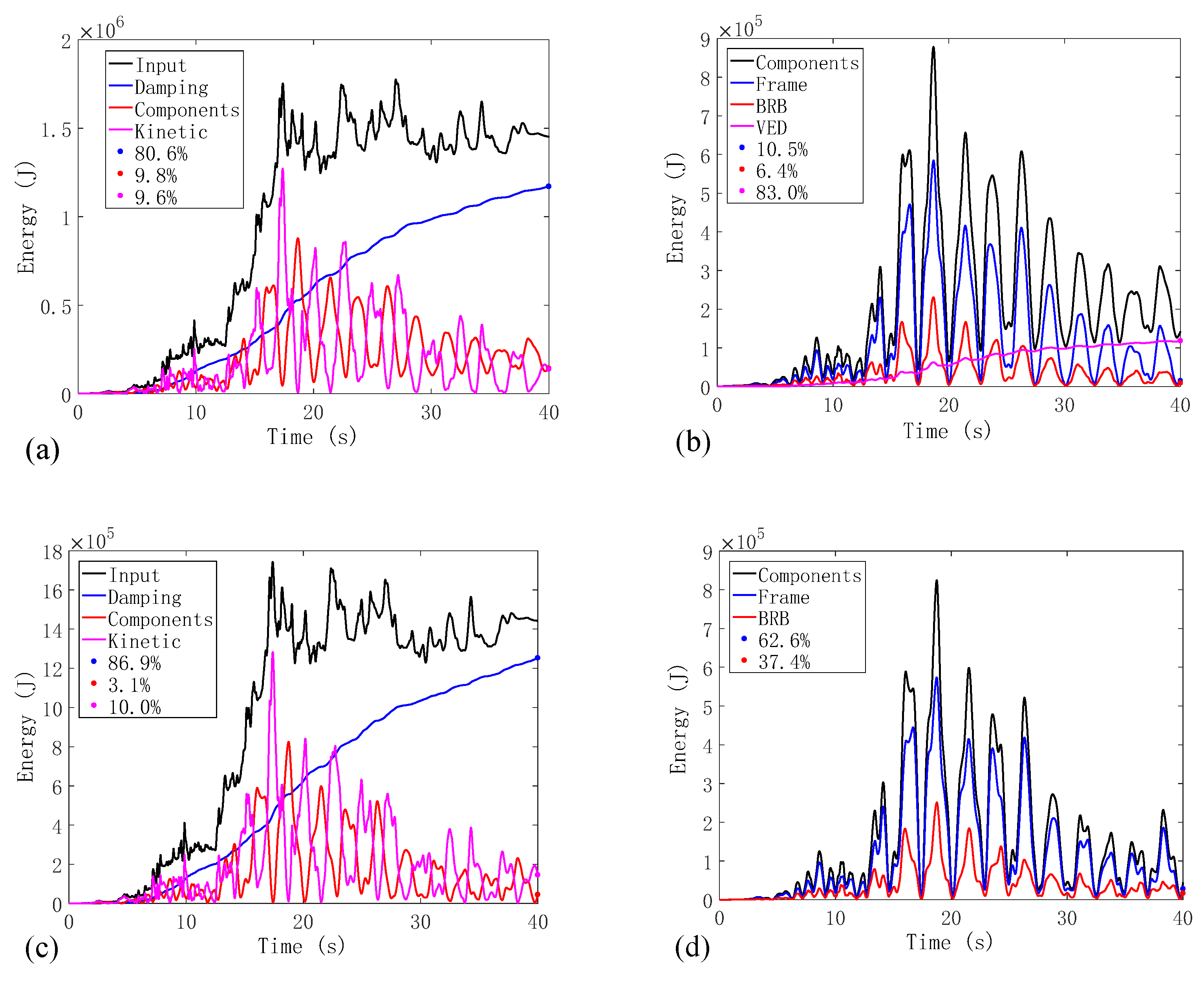
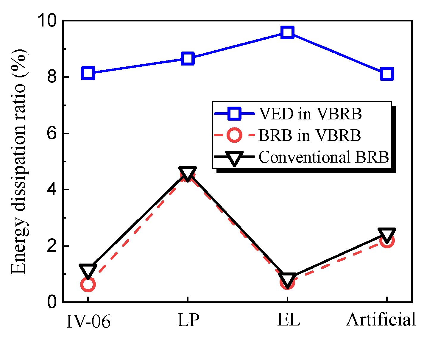
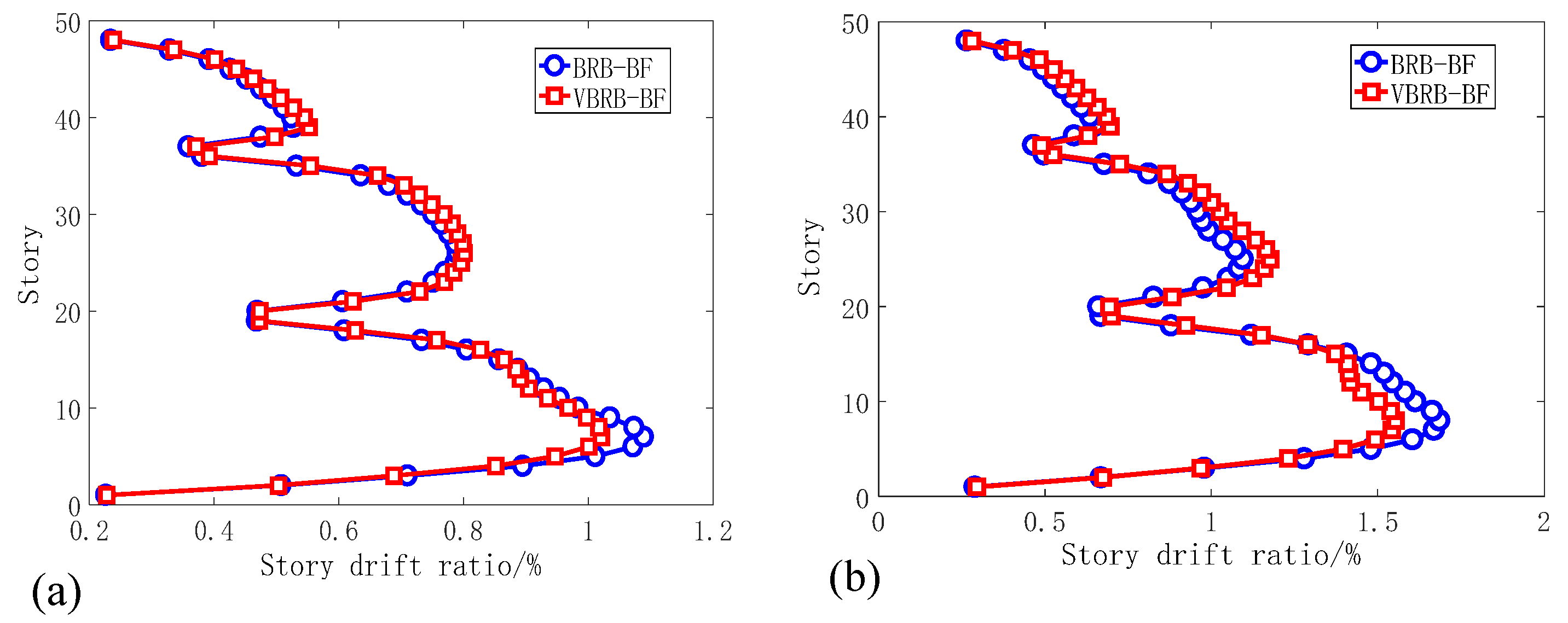
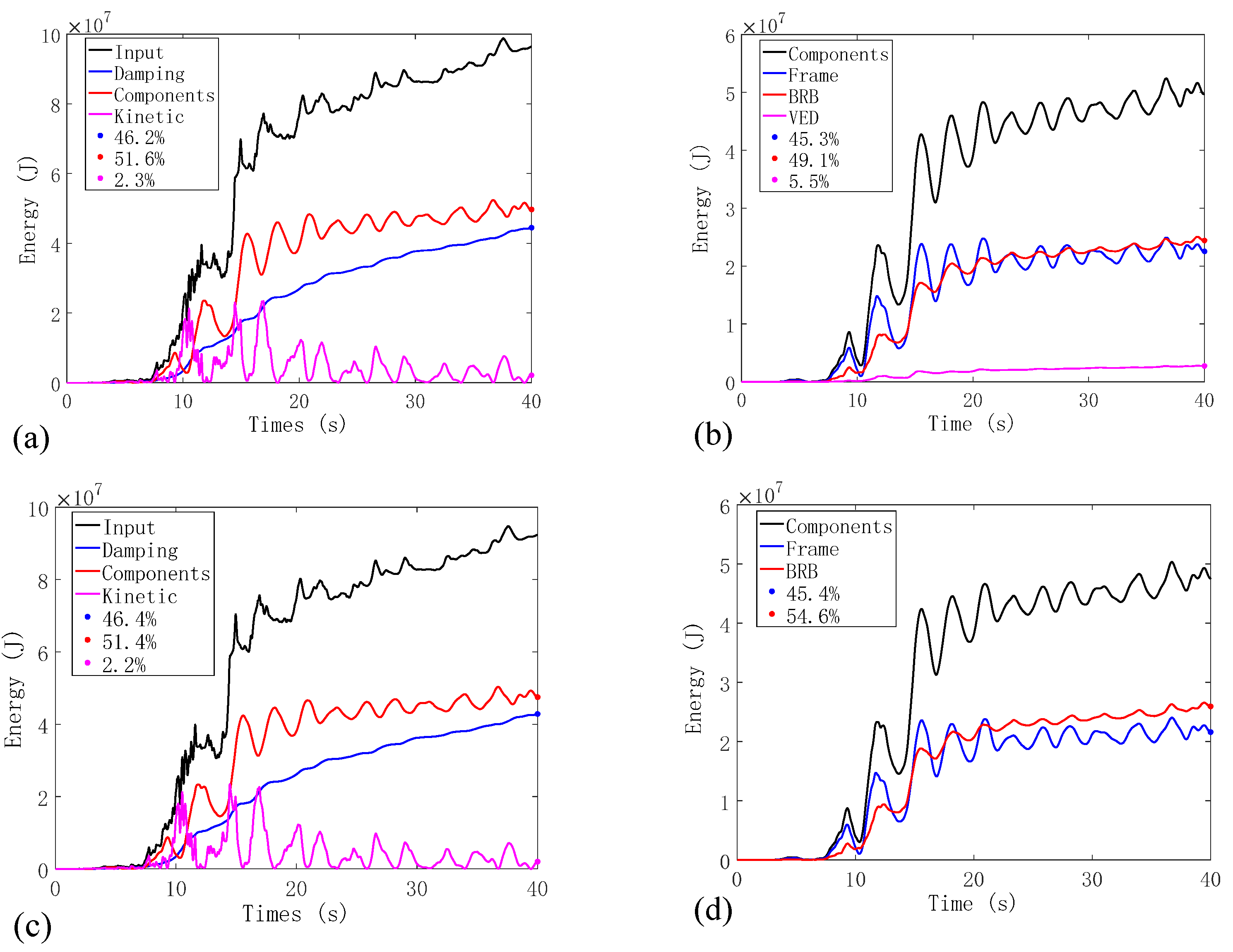
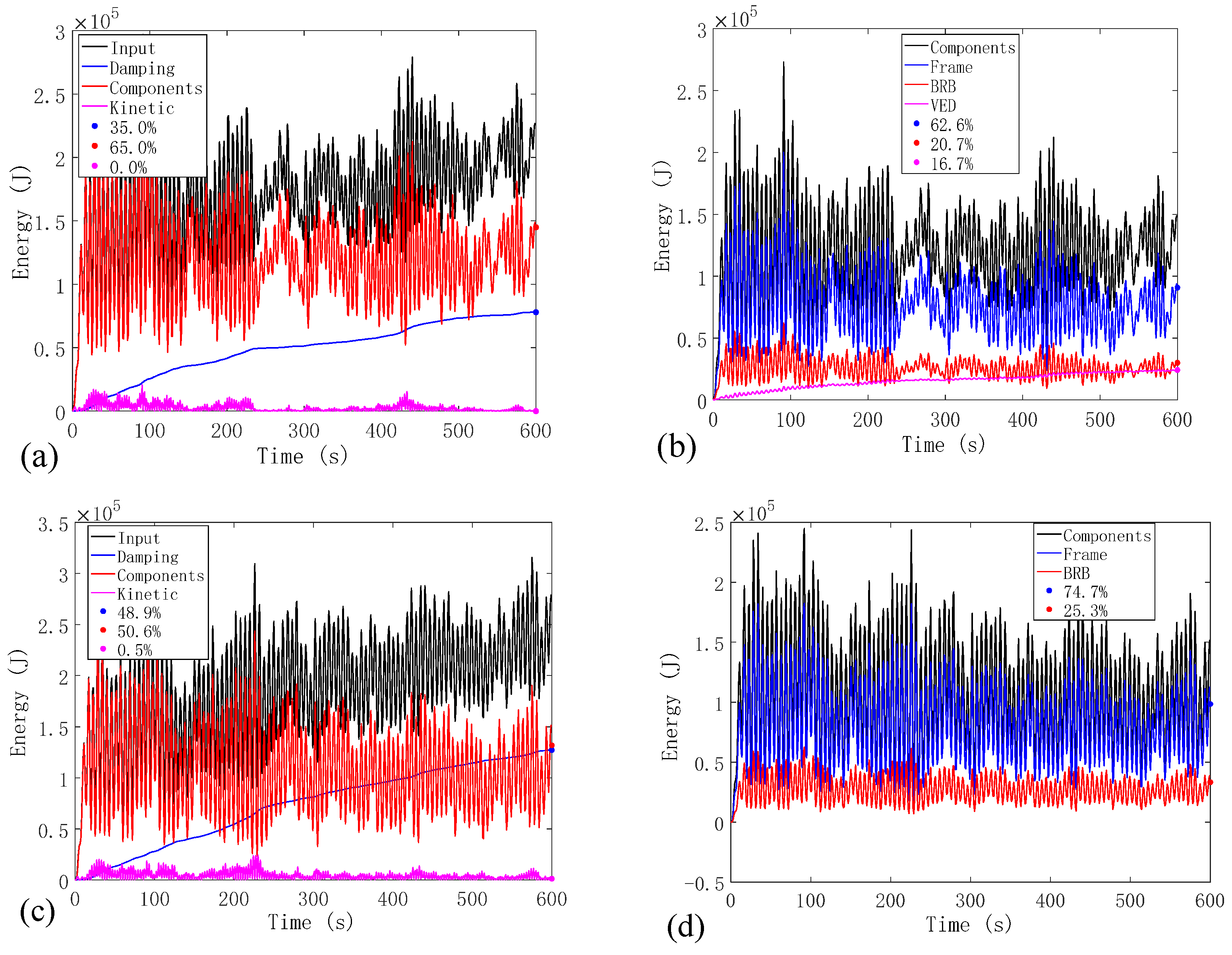
When subjected to FOEs, the lateral drift response of VBRB-BF is generally smaller than that of BRB-BF. A BRB in a VBRB stores elastic strain energy comparable to a conventional BRB, while a VED in a VBRB dissipates 8%–10% of the seismic energy. On account of the contribution from the VED, a better drift reduction effect can be expected in VBRB-BF compared with BRB-BF.
(4)
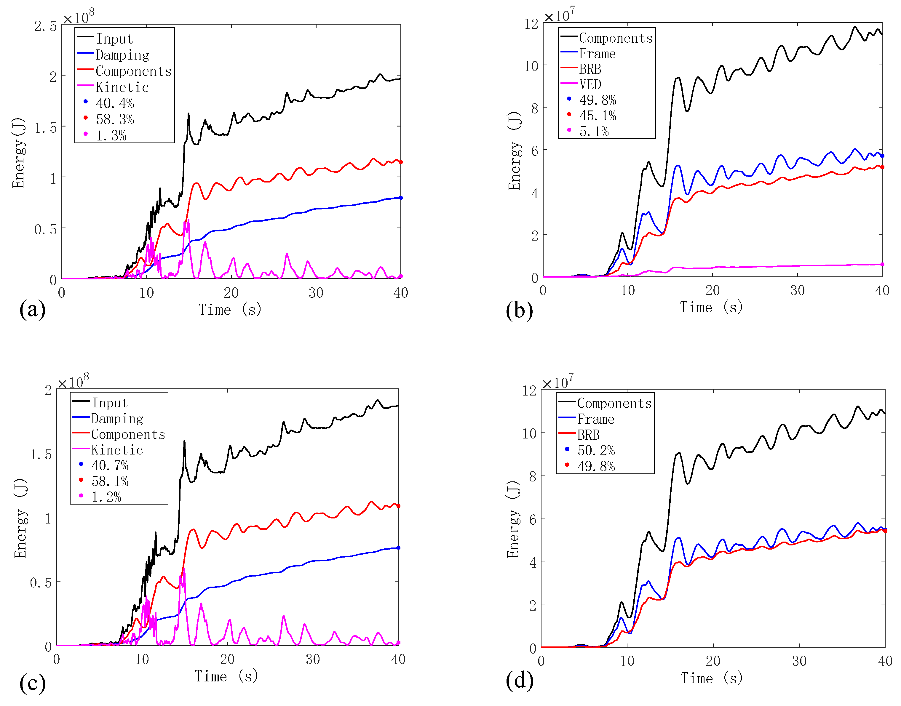
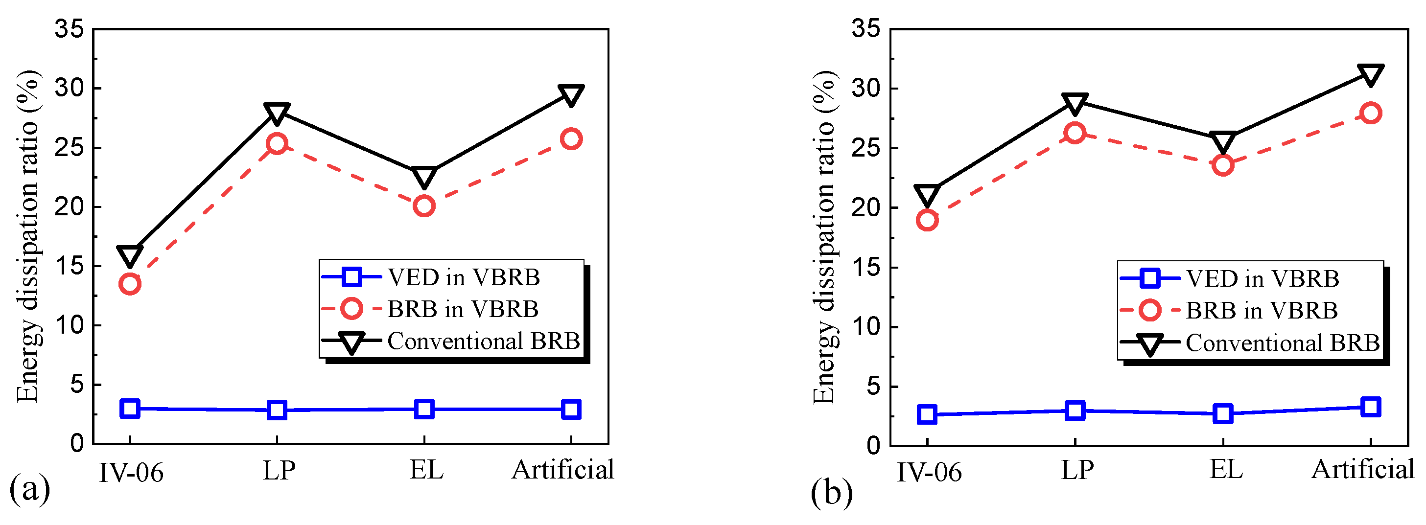
Under MCE and SRE, the inter-story drift distribution of VBRB-BF is similar to that of BRB-BF. A BRB in BRB-BF consumes comparable seismic energy as a VBRB in VBRB-BF. In a VBRB, the BRB acts as the primary energy dissipation component while the VED consumes no more than 5% of the seismic input energy.
(5)
When subjected to wind loads, the lateral drift response of VBRB-BF is generally smaller than that of BRB-BF. A VBRB provides approximately 1%~2% of the viscous damping ratio, which is effective in reducing the wind-induced structural vibration. By providing stable energy dissipation, a VBRB is not only efficient in reducing the wind-induced vibration in magnitude, but also conducive to attenuating the response fluctuation.

Author Contributions

Conceptualization, J.O. and N.M.; methodology, X.Z. and T.S.; software, B.S.; validation, X.Z., T.S. and B.S.; formal analysis, X.Z. and T.S.; investigation, X.Z.; resources, B.S. and N.M.; data curation, X.Z.; writing—original draft preparation, X.Z. and T.S.; writing—review and editing, X.Z. and T.S.; visualization, N.M.; supervision, J.O.; project administration, J.O.; funding acquisition, J.O. All authors have read and agreed to the published version of the manuscript.

Funding

This research was funded by the “National Natural Science Foundation of China, grant numbers 52108439 and 52108133”, the “National Key R&D Program of China, grant number 2018YFC0705603”, the “Jiangsu Province Natural Science Foundation, grant number BK20210371”, and the “Fundamental Research Funds for the Central Universities, grant number B210201019”.

Institutional Review Board Statement

Not applicable.

Informed Consent Statement

Not applicable.

Data Availability Statement

Data supported the reported results can be found in publicly achieved datasets analyzed during the study.

Conflicts of Interest

The authors declare no conflict of interest.

References

  1. Abou-Elfath, H.; Ramadan, M.; Alkanai, F.O. Upgrading the seismic capacity of existing RC buildings using buckling restrained braces. Alex. Eng. J. 2017, 56, 251–262. [Google Scholar] [CrossRef]
  2. Kimura, K.; Yoshioka, K.; Takeda, T. Tests on Braces Encased by Mortar in-Filled Steel Tubes; Summaries of Technical Papers of Annual Meeting; Architectural Institute of Japan: Tokyo, Japan, 1976. [Google Scholar]
  3. Wang, C.; Chen, Q.; Zeng, B. A novel brace with partial buckling restraint: An experimental and numerical investigation. Eng. Struct. 2017, 150, 190–202. [Google Scholar] [CrossRef]
  4. Saeki, E.; Maeda, Y.; Nakamura, H. Experimental study on practical-scale unbonded braces. J. Struct. Constr. Eng. Archit. Inst. Jpn. 1995, 476, 149–158. [Google Scholar] [CrossRef] [Green Version]
  5. Nagao, N.; Takahashi, S. A study on the elasto-plastic behavior of unbonded composite bracing (Part 1: Experiments on isolated members under cyclic loading). J. Struct. Eng. 1990, 415, 105–115. [Google Scholar]
  6. Suzuki, N.; Kono, R.; Higasibata, Y. Experimental Study on the H-Section Steel Brace Encased in Rc or Steel Tube; Summaries of Technical Papers of Annual Meeting; Japan Association for Wind Engineering: Tokyo, Japan, 1994. [Google Scholar]
  7. Kim, D.H.; Lee, C.H.; Ju, Y.K. Subassemblage test of buckling-restrained braces with H-shaped steel core. Struct. Des. Tall Spec. Build. 2015, 24, 243–256. [Google Scholar] [CrossRef]
  8. Nakamura, H.; Takeuchi, T.; Maeda, Y.; Nakata, Y.; Sasaki, T.; Iwata, M.; Wada, A. Fatigue properties of practical-scale unbonded braces. Jitsudai Anbondo Buresu No Hiro Seino Ni Kansuru Kenkyu 1998, 372, 49–55. [Google Scholar]
  9. Tremblay, R.; Bolduc, P.; Neville, R. Seismic testing and performance of buckling-restrained bracing systems. Can. J. Civ. Eng. 2006, 33, 183–198. [Google Scholar] [CrossRef]
  10. Takeuchi, T.; Ida, M.; Yamada, S. Estimation of cumulative deformation capacity of buckling restrained braces. J. Struct. Eng. 2008, 134, 822–831. [Google Scholar] [CrossRef]
  11. Takeuchi, T.; Hajjar, J.F.; Matsui, R. Local buckling restraint condition for core plates in buckling restrained braces. J. Constr. Steel Res. 2010, 66, 139–149. [Google Scholar] [CrossRef]
  12. Xie, Q. State of the art of buckling-restrained braces in Asia. J. Constr. Steel Res. 2005, 61, 727–748. [Google Scholar] [CrossRef]
  13. Sabelli, R.; Mahin, S.; Chang, C. Seismic demands on steel braced frame buildings with buckling-restrained braces. Eng. Struct. 2003, 25, 655–666. [Google Scholar] [CrossRef]
  14. Maley, T.J.; Sullivan, T.J.; Corte, G.D. Development of a displacement-based design method for steel dual systems with buckling-restrained braces and moment-resisting frames. J. Earthq. Eng. 2010, 14, 106–140. [Google Scholar] [CrossRef]
  15. Choi, H.; Kim, J. Energy-based seismic design of buckling-restrained braced frames using hysteretic energy spectrum. Eng. Struct. 2006, 28, 304–311. [Google Scholar] [CrossRef]
  16. Bai, J.; Chen, H.; Zhao, J. Seismic design and subassemblage tests of buckling-restrained braced RC frames with shear connector gusset connections. Eng. Struct. 2021, 234, 112018. [Google Scholar] [CrossRef]
  17. Chou, C.; Tsai, W.; Chung, P. Development and validation tests of a dual-core self-centering sandwiched buckling-restrained brace (SC-SBRB) for seismic resistance. Eng. Struct. 2016, 121, 30–41. [Google Scholar] [CrossRef]
  18. Miller, D.J.; Fahnestock, L.A.; Eatherton, M.R. Development and experimental validation of a nickel–titanium shape memory alloy self-centering buckling-restrained brace. Eng. Struct. 2012, 40, 288–298. [Google Scholar] [CrossRef]
  19. Nazarimofrad, E.; Shokrgozar, A. Seismic performance of steel braced frames with self-centering buckling-restrained brace utilizing superelastic shape memory alloys. Struct. Des. Tall Spec. Build. 2019, 28, e1666. [Google Scholar] [CrossRef]
  20. Christopoulos, C.; Tremblay, R.; Kim, H.J. Self-Centering Energy Dissipative Bracing System for the Seismic Resistance of Structures: Development and Validation. J. Struct. Eng. 2008, 134, 96–107. [Google Scholar] [CrossRef]
  21. Xu, L.; Fan, X.; Li, Z. Cyclic behavior and failure mechanism of self-centering energy dissipation braces with pre-pressed combination disc springs. Earthq. Eng. Struct. Dyn. 2017, 46, 1065–1080. [Google Scholar] [CrossRef]
  22. Xu, L.; Chen, P.; Li, Z. Development and validation of a versatile hysteretic model for pre-compressed self-centering buckling-restrained brace. J. Constr. Steel Res. 2021, 177, 106473. [Google Scholar] [CrossRef]
  23. Pan, P.; Li, W.; Nie, X. Seismic performance of a reinforced concrete frame equipped with a double-stage yield buckling restrained brace. Struct. Des. Tall Spec. Build. 2017, 26, e1335. [Google Scholar] [CrossRef]
  24. Kim, D.H.; Ju, Y.K.; Kim, M.H. Wind-induced vibration control of tall buildings using hybrid buckling-restrained braces. Struct. Des. Tall Spec. Build. 2014, 23, 549–562. [Google Scholar] [CrossRef]
  25. Kim, D.H.; Ju, Y.K.; Kim, M.H. Experimental Study on the Vibration Control Capacity of Hybrid Buckling-Restrained Braces. J. Korean Soc. Steel Constr. 2009, 21, 83–91. [Google Scholar]
  26. Lakes, R.S. Viscoelastic measurement techniques. Rev. Sci. Instrum. 2004, 75, 797–810. [Google Scholar]
  27. Xu, Z.D.; Liao, Y.X.; Ge, T. Experimental and theoretical study of viscoelastic dampers with different matrix rubbers. J. Eng. Mech. 2016, 142, 04016051. [Google Scholar] [CrossRef]
  28. Schwarz, R.B.; Vuorinen, J.F. Resonant ultrasound spectroscopy: Applications, current status and limitations. J. Alloys Compd. 2000, 310, 243–250. [Google Scholar] [CrossRef]
  29. Lee, T.; Lakes, R.S.; Lal, A. Resonant ultrasound spectroscopy for measurement of mechanical damping: Comparison with broadband viscoelastic spectroscopy. Rev. Sci. Instrum. 2000, 71, 2855–2861. [Google Scholar] [CrossRef] [Green Version]
  30. Tsai, C.S. Temperature effect of viscoelastic dampers during earthquakes. J. Struct. Eng. 1994, 120, 394–409. [Google Scholar] [CrossRef]
  31. Chang, K.C.; Soong, T.T.; Oh, S. Seismic behavior of steel frame with added viscoelastic dampers. J. Struct. Eng. 1995, 121, 1418–1426. [Google Scholar] [CrossRef]
  32. Bergman, D.M.; Hanson, R.D. Viscoelastic mechanical damping devices tested at real earthquake displacements. Earthq. Spectra 1993, 9, 389–417. [Google Scholar] [CrossRef]
  33. Park, S.W. Analytical modeling of viscoelastic dampers for structural and vibration control. Int. J. Solids Struct. 2001, 38, 8065–8092. [Google Scholar] [CrossRef]
  34. Xu, Z.; Wang, D.; Shi, C. Model, tests and application design for viscoelastic dampers. J. Vib. Control. 2011, 17, 1359–1370. [Google Scholar] [CrossRef]
  35. Chang, K.C.; Soong, T.T.; Oh, S.T. Seismic Response of a 2/5 Scale Steel Structure with Added Viscoelastic Dampers. Report No. NCEER 91, 1991, 12. Available online: https://www.eng.buffalo.edu/mceer-reports/91/91-0012.pdf (accessed on 18 July 2022).
  36. Chang, K.; Lin, Y. Seismic response of full-scale structure with added viscoelastic dampers. J. Struct. Eng. 2004, 130, 600–608. [Google Scholar] [CrossRef]
  37. Open System for Earthquake Engineering Simulation (OpenSees) Pacific Earthquake Engineering Research Center. Univ. of California, 2013. Available online: https://apps.peer.berkeley.edu/products/opensees.html (accessed on 16 July 2022).
  38. Kang, J. Seismic Performance Analysis and Design of High-Rise Buildings with Energy Dissipation Devices under Super-Strong Earthquake. Master’s Thesis, Dalian Polytechnic University, Dalian, China, May 2015. [Google Scholar]
  39. GB50011-2010; Code for Seismic Design of Buildings. Ministry of Construction of the People’s Republic of China: Beijing, China, 2010.
Figure 1. Simplified hysteretic model and construction details of a VBRB: (a) restoring force models for BRB, VED and VBRB; and (b) construction details of a VBRB.
Buildings 12 01159 g001
Figure 2. Configuration and assembly of VBRB specimens: (a) assembly of BRB; (b) assembly of VED; and (c) schematic and sectional drawing of VBRB specimen.
Buildings 12 01159 g002
Figure 3. Loading instrument and loading protocol: (a) loading instrument; and (b) loading protocols.
Buildings 12 01159 g003
Figure 4. Hysteresis curves of VBRB (displacement dependency): (a) VBRB1, 0.2 Hz, γ = (20~80%); (b) VBRB1, 0.2 Hz, γ = (120~200%); (c) VBRB2, 0.3 Hz, γ = (20~80%); (d) VBRB2, 0.3 Hz, γ = (120~200%); (e) VBRB3, 0.6 Hz, γ = (20~80%); and (f) VBRB3, 0.6 Hz, γ = (120~200%).
Buildings 12 01159 g004
Figure 5. Hysteresis curves of VBRB (frequency dependency): (a) γ = 20%, ε = 0.24%; (b) γ = 40%, ε = 0.48%; (c) γ = 80%, ε = 0.95%; (d) γ = 120%, ε = 1.43%; (e) γ = 160%, ε = 1.91%; and (f) γ = 200%, ε = 2.38%.
Buildings 12 01159 g005
Figure 6. Parametric design procedures for VBRB-equipped structures.
Buildings 12 01159 g006
Figure 7. Elevation and plane layout of the structure for case study: (a) elevation; (b) plane layout; and (c) analytical model for BRB-BF/VBRB-BF.
Buildings 12 01159 g007
Figure 8. Dynamic model of VBRB.
Buildings 12 01159 g008
Figure 9. Ground motion input: (a) El Centrol (1940); (b) Imperial Valley−06 (1979); (c) Loma Prieta (1989); and (d) artificial.
Buildings 12 01159 g009
Figure 10. Responses of the maximum lateral drift ratio (PGA = 70 cm/s2) underground motions: (a) El Centrol; (b) Imperial Valley-06; (c) Loma Prieta; (d) artificial; and (e) average response.
Buildings 12 01159 g010
Figure 11. Seismic energy analysis (Imperial Valley-06 case, PGA = 70 cm/s2): (a) energy distribution (VBRB-BF); (b) energy absorbed by components (VBRB-BF); (c) energy distribution (BRB-BF); and (d) energy absorbed by components (BRB-BF).
Buildings 12 01159 g011
Figure 12. Energy dissipation ratio of the brace (PGA = 70 cm/s2).
Buildings 12 01159 g012
Figure 13. Average responses of the maximum lateral drift ratio: (a) PGA = 400 cm/s2 (MCE); and (b) PGA = 620 cm/s2 (SRE).
Buildings 12 01159 g013
Figure 14. Seismic energy analysis (Loma Prieta case, PGA = 400 cm/s2): (a) energy distribution (VBRB-BF); (b) energy absorbed by components (VBRB-BF); (c) energy distribution (BRB-BF); and (d) energy absorbed by components (BRB-BF).
Buildings 12 01159 g014
Figure 15. Seismic energy analysis (Loma Prieta case, PGA = 620 cm/s2): (a) energy distribution (VBRB-BF); (b) energy absorbed by components (VBRB-BF); (c) energy distribution (BRB-BF); and (d) energy absorbed by components (BRB-BF).
Buildings 12 01159 g015
Figure 16. Energy dissipation ratio of the brace: (a) PGA = 400 cm/s2; and (b) PGA = 620 cm/s2.
Buildings 12 01159 g016
Figure 17. Generated wind pressure time histories: (a) wind 01; (b) wind 02; (c) wind 03; (d) wind 04; and (e) wind 05.
Buildings 12 01159 g017aBuildings 12 01159 g017b
Figure 18. Average values of wind-induced structural responses: (a) distributions of maximum lateral drift ratio; (b) roof acceleration time-histories; and (c) roof displacement time histories.
Buildings 12 01159 g018
Figure 19. Energy analysis caused by wind-induced vibration: (a) energy distribution (VBRB-BF); (b) energy absorbed by components (VBRB-BF); (c) energy distribution (BRB-BF); and (d) energy absorbed by components (BRB-BF).
Buildings 12 01159 g019
Table 1. Material properties of PR04 rubber.
ParametersFrequency
(Hz)
Shear Strain (%)
10%30%50%100%150%200%
Shear modulus (Mpa)0.20.830.620.490.340.310.28
0.30.920.630.520.360.320.28
0.60.830.620.490.340.310.28
Loss factor0.20.230.310.400.370.320.25
0.30.230.310.430.390.330.28
0.60.460.400.400.370.320.25
Table 2. Geometric parameters of VBRB specimens.
BRB VED
Length
(mm)
Area of Yield
Segment (mm2)
Length of Yield
Segment (mm)
Section of
Casing (mm)
Area
(mm2)
Rubber Thickness
(mm)
1100640920□68 × 68 × 8 × 8208,00010
Table 3. Loading protocols.
StepLoad Protocols
(mm)
ε B R B ( % ) 1 γ V E D ( % ) 2Reversed Cycles
1 F = 80 sin ( 2 π f t ) /kN--20
2 D = 2 sin ( 2 π f t ) 0.24203
3 D = 4 sin ( 2 π f t ) 0.48403
4 D = 8 sin ( 2 π f t ) 0.95803
5 D = 12 sin ( 2 π f t ) 1.431203
6 D = 16 sin ( 2 π f t ) 1.901603
7 D = 20 sin ( 2 π f t ) 2.382003
1 ε B R B -maximum axial strain of BRB component in current step; 2 γ V E D -maximum shear strain of VED component in current step.
Table 4. Sectional information of the mega braced frame.
Structural ComponentStorySection Size
Mega column1~24□900 × 900 × 65 × 65
25~36□800 × 800 × 40 × 40
37~48□700 × 700 × 30 × 30
Frame column1~24□800 × 800 × 60 × 60
25~48□750 × 750 × 50 × 50
Mega girder1~48I 800 × 300 × 19 × 35
Frame beam1~48HN 692 × 300 × 13 × 20
Cross beam in mega columns1~48HN 700 × 300 × 13 × 24
Table 5. Parameters of the viscoelastic material.
G/MpaηG′/MpaG″/MpaA/m2h/m
0.1460.70.120.08420.02
Note: G , η, G′, and, G″ represent the shear modulus, loss modulus, shear storage modulus, and shear loss modulus of the viscoelastic material, respectively; A and h represent the shear area and thickness of the rubber layer in the VED, respectively.
Table 6. Design parameters of VBRB.
Parameters of VED Parameters of BRB
C V E D
kNs/mm
K V E D
kN/mm
F V E f r e q
kN
F V E r a r e
kN
ξ a d d K B R B
kN/mm
A B R B
mm2
F B R B f r e q
kN
F B R B r a r e
kN
7.97 12.0 67.88678.80.01522563641272.82036.5
Note: C V E D and K V E D denote the damping coefficient and equivalent stiffness of VED, respectively; F V E f r e q and F V E r a r e represent the force in VED at 1/500 and 1/50 drift ratio, respectively; ξ a d d denotes the VED-added damping ratio for the structure under FOE; K B R B and A B R B denote the elastic stiffness of the cross-section area of the BRB; F B R B f r e q and F B R B r a r e denote the force in the BRB at 1/500 and 1/50 drift ratio, respectively.
Table 7. Geometric parameters of the selected BRB brace and rubber.
BRB VED
Length
(mm)
Area of Yield
Segment (mm2)
Length of Yield
Segment (mm)
Section of
Casing (mm)
Area
(mm2)
Rubber
Thickness (mm)
565763644730□250 × 250 × 8 × 82,000,00020
Table 8. Structural wind-induced vibrational responses.
CasesBRB-BFVBRB-BFRelative Error
Maximum Acceleration (m/s2)Root Mean Square (m/s2)Maximum Acceleration (m/s2)Root Mean Square
(m/s2)
Maximum AccelerationRoot Mean Square
Wind 010.06920.02280.06220.016510.1%27.6%
Wind 020.05660.01870.05840.0147−3.2%21.4%
Wind 030.07560.02230.07590.0196−0.4%12.1%
Wind 040.06310.01950.05030.016820.3%13.8%
Wind 050.06920.02090.05930.016114.3%23.0%
Table 9. Additional damping ratio from VBRB.
Energy Dissipation
by VED (J)
Elastic Strain
Energy (J)
Additional Damping
Ratio (%)
Wind12.4152 × 1041.2076 × 1051.59
Wind21.5064 × 1041.0269 × 1051.17
Wind32.8166 × 1041.1412 × 1051.96
Wind41.9571 × 1047.6234 × 1052.04
Wind51.7927 × 1041.1210 × 1051.27
Publisher’s Note: MDPI stays neutral with regard to jurisdictional claims in published maps and institutional affiliations.

