
Passive Night Cooling Potential in Office Buildings in Continental and Mediterranean Climate Zone in Croatia


Abstract
:1. Introduction
2. Methodology
- (1)
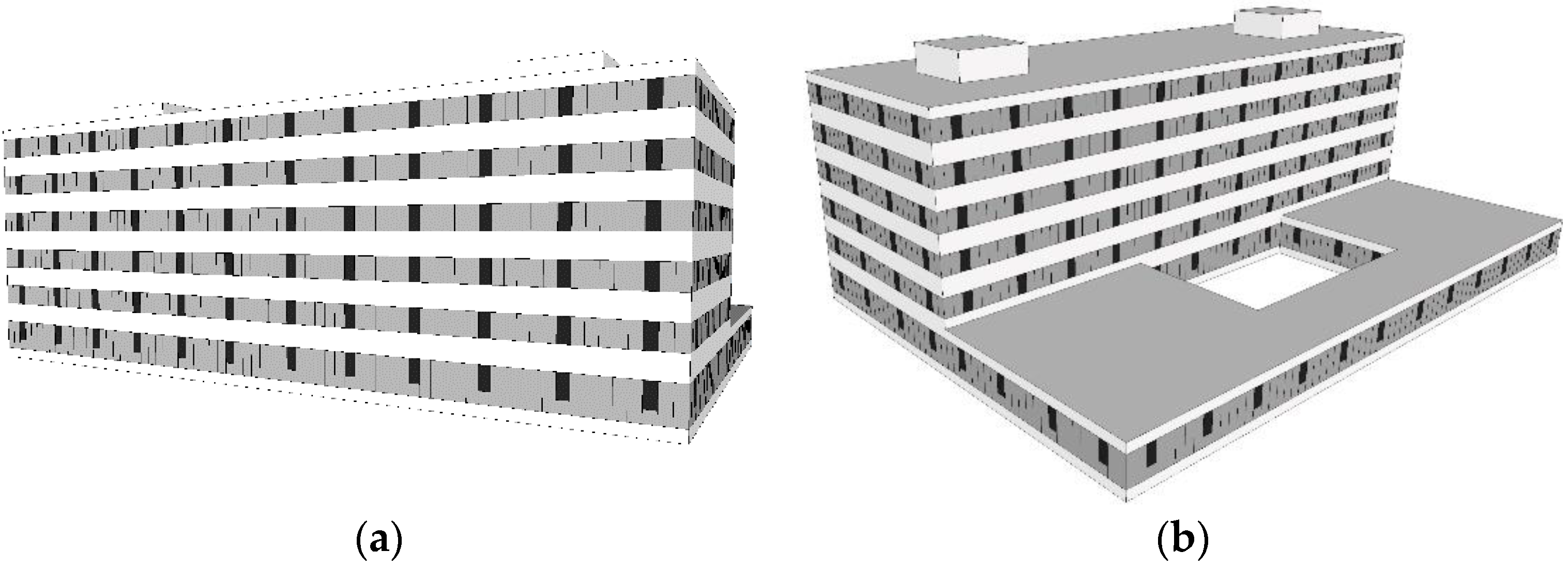
- A model with physical characteristics was created: a prototype of the office building, which corresponds to the standard requirements and regulation conditions for the analysed areas. Moreover, defining building physical characteristics also requires determining heat accumulation, the heat loss coefficient by transmission and ventilation as well as internal and solar heat gains.
- (2)
- The influence of climate conditions on passive cooling was investigated through model aerodynamic properties, such as the orientation of the openings, wind pressure onto the envelope, and the number of air exchanges.
- (3)
- Four cases were defined: two cases for each climate zone, with and without passive night cooling.
- (4)
- Measurements and simulations of passive cooling were conducted by the calculation of cooling energy demands along with the heat absorption of passively ventilated air.
2.1. Model Physical Characteristics
2.1.1. Heat Accumulation
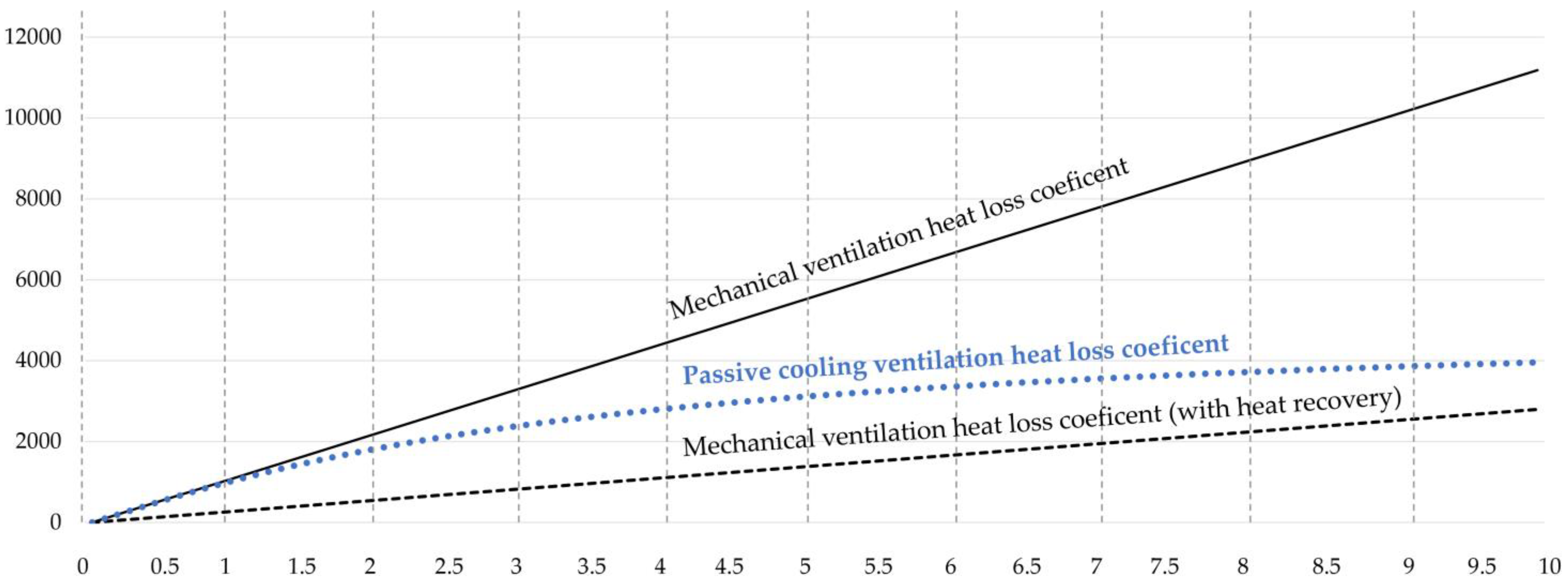
2.1.2. Transmission and Ventilation Heat Loss
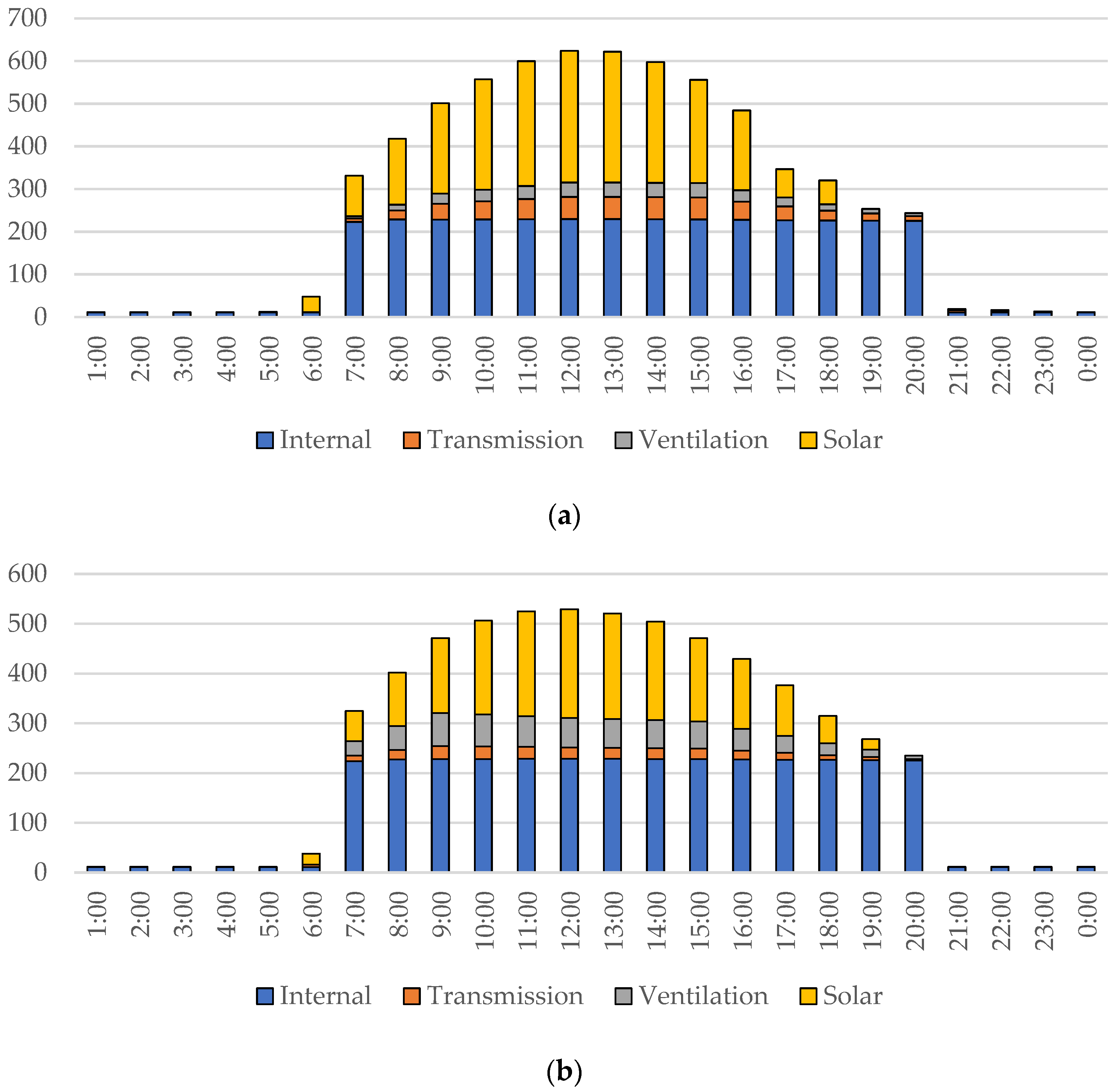
2.1.3. Internal and Solar Heat Gains
2.2. Influence of Climate Conditions on Passive Cooling
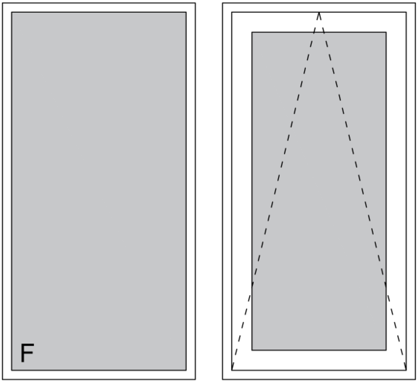
2.2.1. Orientation of the Openings
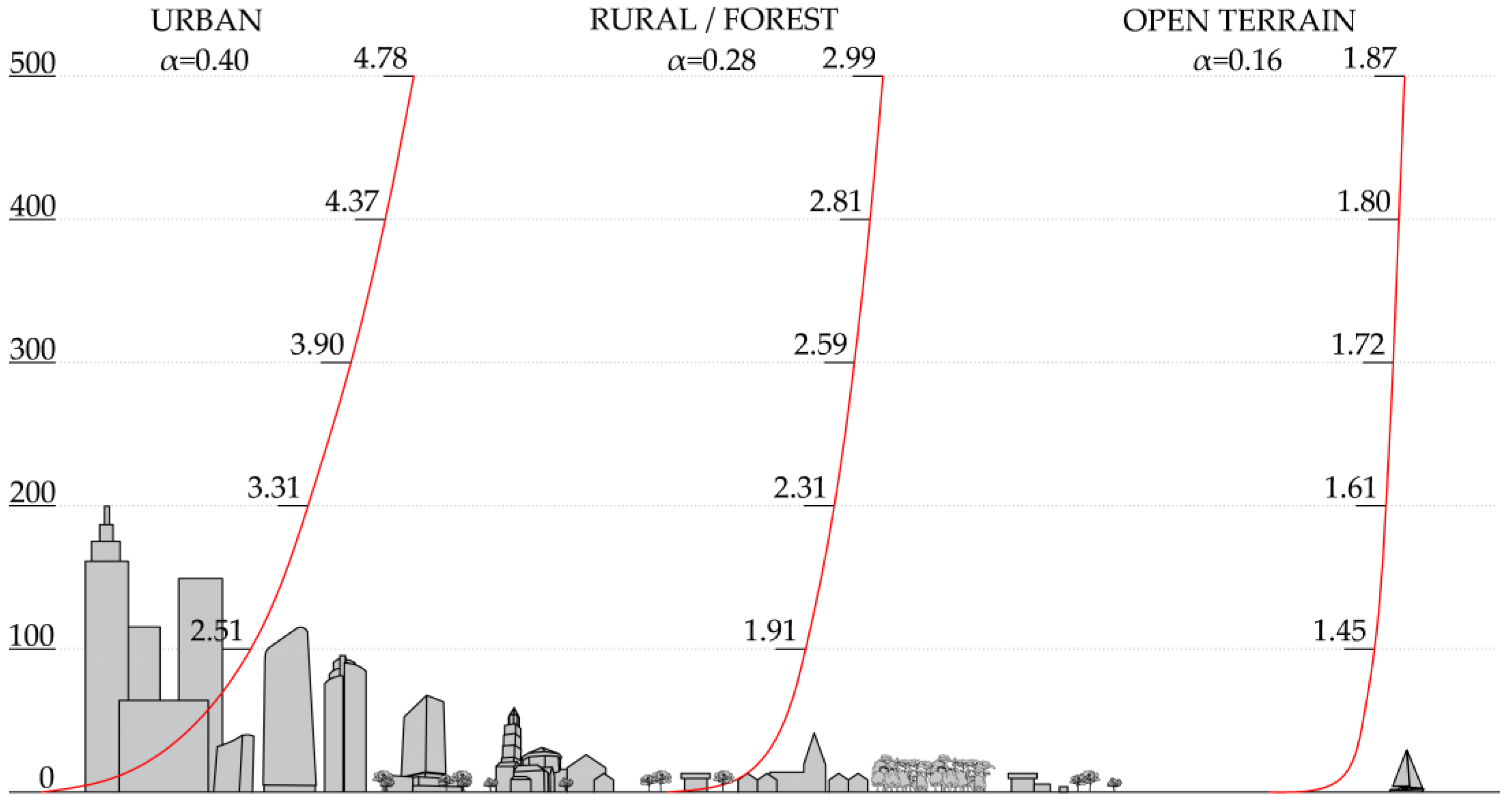
2.2.2. Windspeed
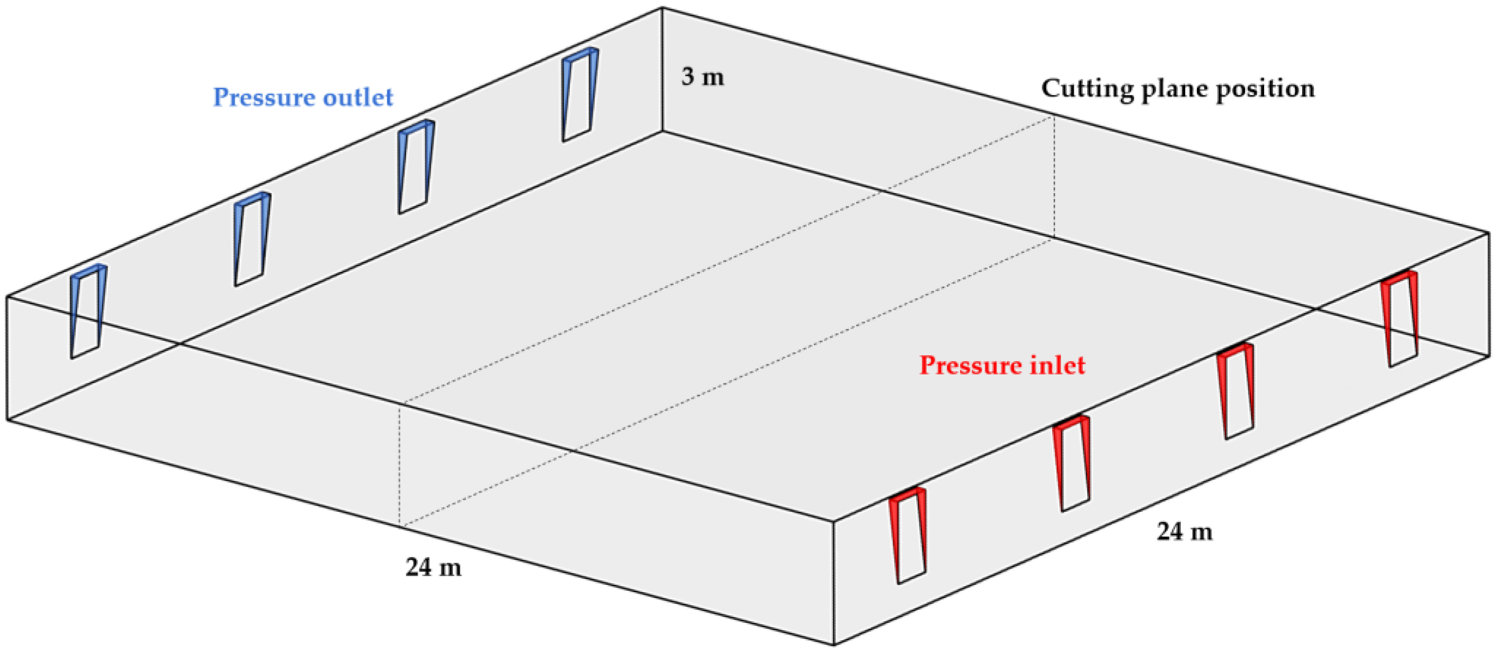
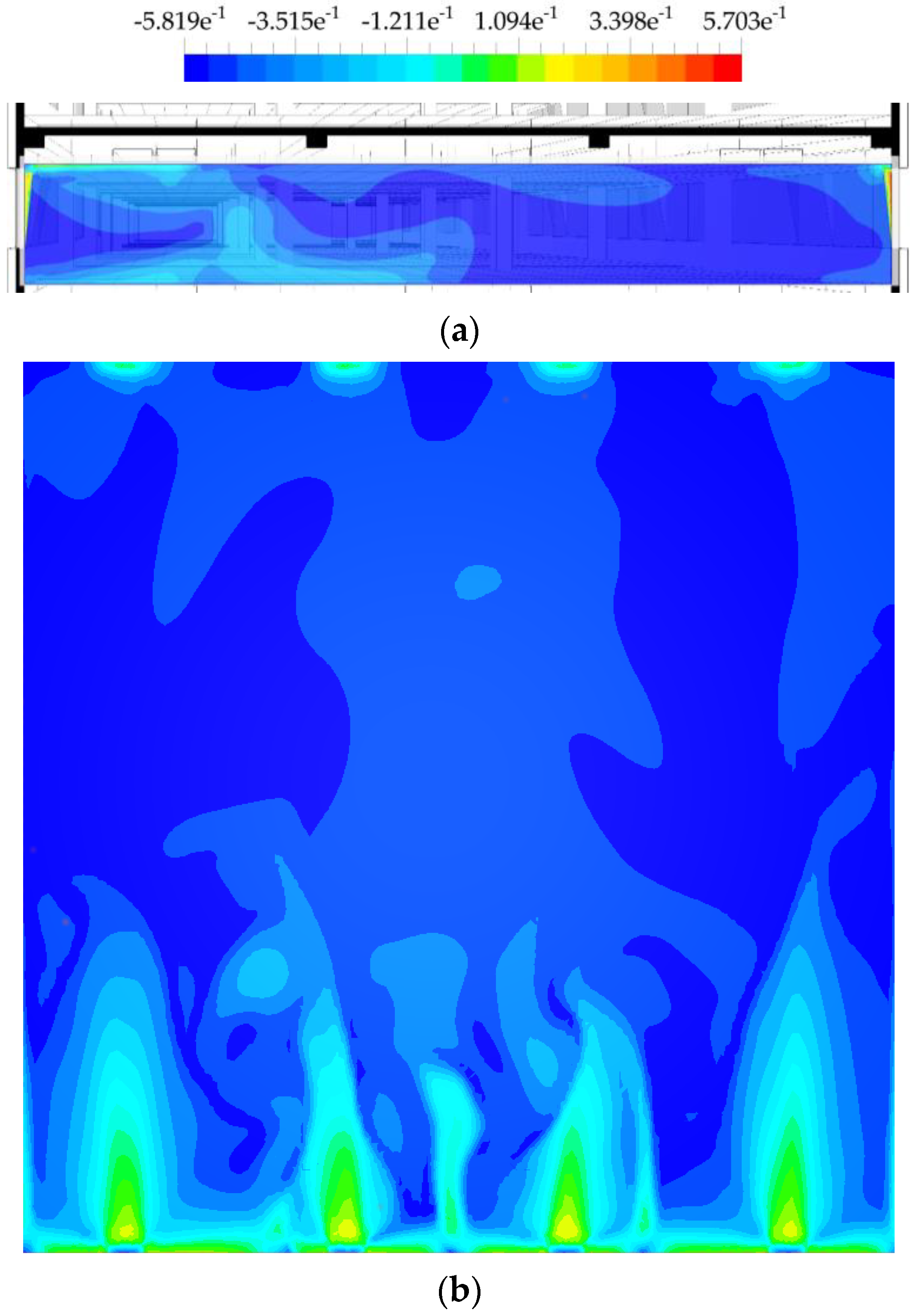
2.2.3. Wind Pressure on the Envelope
2.2.4. Air Exchange Number
2.3. Passive Cooling Calculation
2.3.1. Cooling Energy Demand
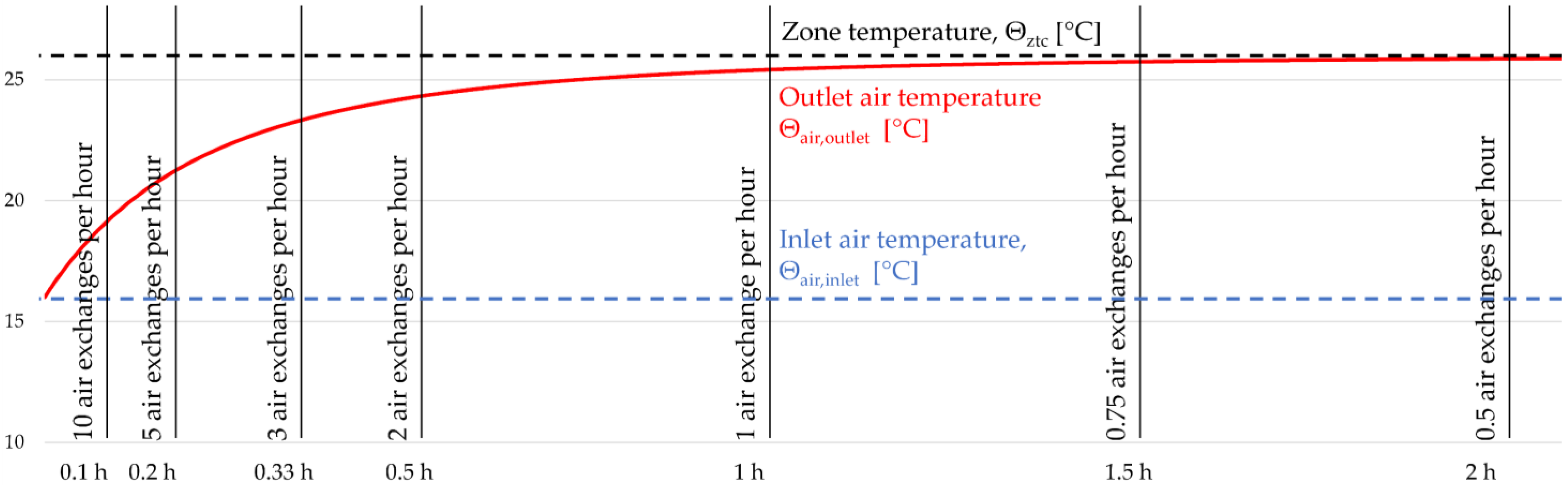
2.3.2. Heat Absorption of Passively Ventilated Air
2.3.3. Mathematical Model
2.4. Cases
2.4.1. Continental Climate Case 1a
2.4.2. Continental Climate Case 2a
2.4.3. Maritime Climate Case 1b
2.4.4. Maritime Climate Case 2b
3. Results
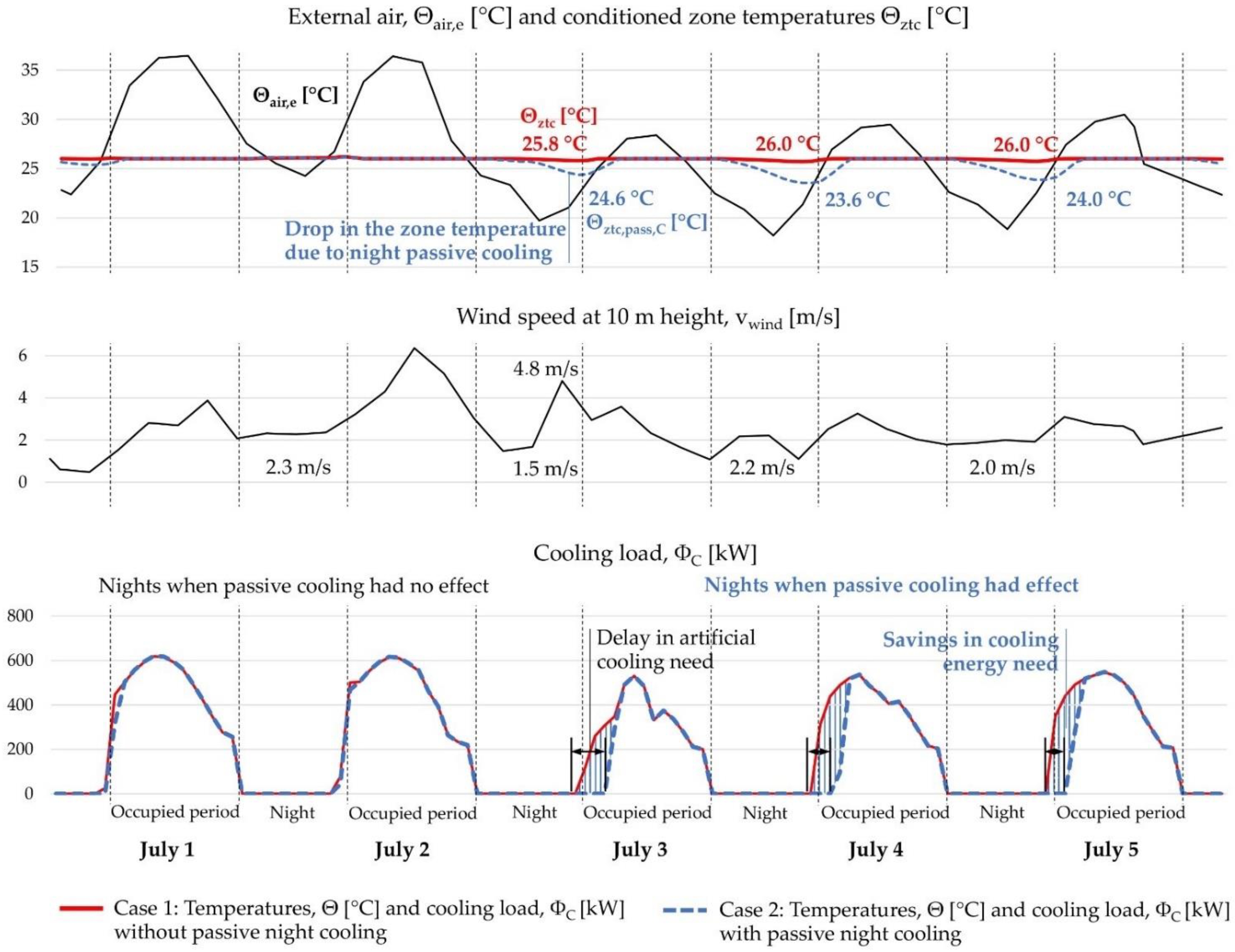
3.1. Continental Climate
3.2. Maritime Climate
3.3. Annual Savings in Cooling Energy
4. Discussion
5. Conclusions
Author Contributions
Funding
Conflicts of Interest
Nomenclature
| List of Symbols | Units | Subscripts | ||
| A | area | [m2] | air | air |
| C | heat capacity | [J/K] | A | appliances |
| c | specific heat capacity | [J/K] | an | annual |
| F | factor | [−] | avg | average |
| g | glazing solar factor | [−] | aux | auxiliary |
| H | height | [m] | C | cooling |
| H | heat loss coefficient | [W/K, W/°C] | c | convection, convective |
| h | surface coefficient of heat transfer | [W/(m2 K), W/(m2 °C)] | day | daily |
| m | mass | [kg] | e | external, outdoor |
| n | number of air exchanges per hour | [1/h] | el | element |
| P | power | [W] | fac | façade |
| p | pressure | [Pa] | f | flow |
| Q | quantity of heat | [J, kWh] | fl | floor |
| q | heat flow density | [W/m2] | fr | frame |
| qv | air volume flow rate | [m3/h] | gl | glazing |
| T | thermodynamic temperature | [K] | gn | gain |
| t | time | [s] | h | hourly |
| U | heat transfer coefficient, thermal transmittance | [W/(m2 K), W/(m2 °C)] | hru | heat recovery unit |
| V | volume | [m3] | int | internal, indoor |
| v | speed, velocity | [m/s] | ld | load |
| w | wind gradient | [−] | m | monthly |
| mech | mechanical (ventilation) | |||
| Greek letters | n | normal | ||
| nd | need | |||
| α | Hellman factor | [−] | noc | unoccupied period |
| γ | azimuth angle | [°] | occ | occupied period |
| η | efficiency | [−] | oel | opaque element |
| θ | Celsius temperature | [°C] | pass | passive |
| ρ | density | [kg/m3] | set | set-point |
| Φ | heat flow rate, heat load, power | [W] | sh | shading |
| Ψ | linear thermal transmittance | [W/(mK), W/(m°C)] | sol | solar |
| TM | thermal bridge | |||
| tr | transmission (heat transfer) | |||
| use | useful | |||
| w | wall, surface | |||
| ve | ventilation (heat transfer) | |||
| w | window | |||
| ztc | thermally conditioned zone | |||
| 50 | 50 pascals | |||
| ∞ | ambient | |||
References
- Veršić, Z.; Muraj, I.; Binički, M. Nearly Zero-Energy Buildings in Croatia: Comparison of Thermal Performance in Different Climatic Regions. In Proceedings of the 42nd IAHS World Congress on Housing, Napulj, Italy, 10–13 April 2018; Volume 13, pp. 16–23. [Google Scholar]
- Prieto, A.; Knaack, U.; Auer, T.; Klein, T. Passive cooling & climate responsive façade design exploring the limits of passive cooling strategies to improve the performance of commercial buildings in warm climates. Energy Build. 2018, 175, 30–47. [Google Scholar] [CrossRef]
- Al-Azri, N.; Zurigat, Y.H.; Al-Rawahi, N. Selection and assessment of passive cooling techniques for residential buildings in oman using a bioclimatic approach. J. Eng. Res. 2013, 10, 52–68. [Google Scholar] [CrossRef] [Green Version]
- Jenkins, D.; Liu, Y.; Peacock, A.D. Climatic and internal factors affecting future UK office heating and cooling energy consumptions. Energy Build. 2008, 40, 874–881. [Google Scholar] [CrossRef]
- European Commission, “Pv Gis.” Joint Research Centre, Energy Efficiency and Renewables Unit. 2012. Available online: http://re.jrc.ec.europa.eu/pvgis/apps4/pvest.php# (accessed on 11 June 2022).
- Bilić, T. Wind direction as one of the problems in navigation on the Adriatic in Greek and roman period. Pomorstvo 2012, 26, 81–93. [Google Scholar]
- Rahman, M.M.; Mashud, M.; Chu, C.M.; Bin Misaran, M.S.; Sarker, M.; Kumaresen, S. A passive cooling system of residential and commercial buildings in summer or hot season. IOP Conf. Ser. Mater. Sci. Eng. 2015, 100, 012031. [Google Scholar] [CrossRef] [Green Version]
- Nunes, A.I.F.; Oliveira Panão, M.J.N. Passive Cooling Load Ratio method. Energy Build. 2013, 64, 209–217. [Google Scholar] [CrossRef] [Green Version]
- Brandl, H. Thermo-active ground-source structures for heating and cooling. Procedia Eng. 2013, 57, 9–18. [Google Scholar] [CrossRef] [Green Version]
- Santamouris, M.; Kolokotsa, D. Passive cooling dissipation techniques for buildings and other structures: The state of the art. Energy Build. 2013, 57, 74–94. [Google Scholar] [CrossRef]
- Ahmed, A.S.F.; Khan, K.M.M.K.; Maung Than Oo, A.A.; Maung Than Oo, A.A.; Rasul, R.M.G. Selection of suitable passive cooling strategy for a subtropical climate. Int. J. Mech. Mater. Eng. 2014, 9, 14. [Google Scholar] [CrossRef] [Green Version]
- Freewan, A.A.Y. Impact of external shading devices on thermal and daylighting performance of offices in hot climate regions. Sol. Energy 2014, 102, 14–30. [Google Scholar] [CrossRef]
- Freewan, A.A.Y. Energy-Efficient Solutions Depending on Building Forms Design with Tilted South and North Facades. Buildings 2022, 12, 753. [Google Scholar] [CrossRef]
- Wei, L.; Tian, W.; Zuo, J.; Yang, Z.Y.; Liu, Y.; Yang, S. Effects of Building Form on Energy Use for Buildings in Cold Climate Regions. Procedia Eng. 2016, 146, 182–189. [Google Scholar] [CrossRef]
- Premrov, M.; Žigart, M.; Žegarac Leskovar, V. Influence of the building shape on the energy performance of timber-glass buildings located in warm climatic regions. Energy 2018, 149, 496–504. [Google Scholar] [CrossRef]
- Caruso, G.; Fantozzi, F.; Leccese, F. Optimal theoretical building form to minimize direct solar irradiation. Sol. Energy 2013, 97, 128–137. [Google Scholar] [CrossRef]
- Hemsath, T.L.; Alagheband Bandhosseini, K. Sensitivity analysis evaluating basic building geometry’s effect on energy use. Renew. Energy 2015, 76, 526–538. [Google Scholar] [CrossRef]
- Bayoumi, M. Improving natural ventilation conditions on semi-outdoor and indoor levels in warm-humid climates. Buildings 2018, 8, 75. [Google Scholar] [CrossRef] [Green Version]
- Oropeza-Perez, I. The influence of an integrated driving on the performance of different passive heating and cooling methods for buildings. Buildings 2019, 9, 224. [Google Scholar] [CrossRef] [Green Version]
- Samuel, D.G.L.; Nagendra, S.M.S.; Maiya, M.P. Passive alternatives to mechanical air conditioning of building: Areview. Build. Environ. 2013, 66, 54–64. [Google Scholar] [CrossRef]
- Breesch, H.; Bossaer, A.; Janssens, A. Passive cooling in a low-energy office building. Sol. Energy 2005, 79, 682–696. [Google Scholar] [CrossRef]
- Kaduchová, K.; Lenhard, R. Numerical simulation of passive cooling beam and its optimization to increase the cooling power. Processes 2021, 9, 1478. [Google Scholar] [CrossRef]
- Roulet, C.A.; Van Der Maas, J.; Flourentzou, F. A planning tool for passive cooling of buildings. Indoor Air 96 1996, 96, 265–270. [Google Scholar]
- Roulet, C.-A.; Van der Maas, J.; Flourentzou, F. Application of Passive Convective Cooling to Buildings. Available online: https://www.researchgate.net/publication/37409999_Application_of_Passive_Convective_Cooling_to_Buildings (accessed on 12 June 2022).
- Flourentzou, F.; van der Maas, J.; Roulet, C.-A. Experiments in Natural Ventilation for Passive Cooling. 1995, pp. 17–20. Available online: https://www.aivc.org/sites/default/files/members_area/medias/pdf/Conf/1996/Flourentzou.pdf (accessed on 12 June 2022).
- van der Maas, J.; Roulet, C.A. Nighttime ventilation by stack effect. ASHRAE Trans. 1991, 97, 516–524. [Google Scholar]
- Flourentzou, F.; van der Maas, J.; Roulet, C.-A. A simple model for free cooling calculations. In Proceedings of the ICSBAT ‘91 Conference Internationale “Energie Solaire et Batiment”, Lausanne, Switzerland, 10–11 October 1991; pp. 239–245. [Google Scholar]
- Roulet, C. Multizone Cooling Model for Calculating the Potential of Night Time; Energy Impact of Ventilation and Air Infiltration Calculating the Potential of Night Time Ventilation Authors: Jacobus Van Der Maas and Claude-Alain Roulet. January 1993. 2017. Available online: https://www.researchgate.net/publication/299600884 (accessed on 25 May 2022).
- Pesic, N.; Calzada, J.R.; Alcojor, A.M. Assessment of advanced natural ventilation space cooling potential across Southern European coastal region. Sustainability 2018, 10, 3029. [Google Scholar] [CrossRef] [Green Version]
- Zamani, Z.; Heidari, S.; Hanachi, P. Reviewing the thermal and microclimatic function of courtyards. Renew. Sustain. Energy Rev. 2018, 93, 580–595. [Google Scholar] [CrossRef]
- Datta, G. Effect of fixed horizontal louver shading devices on thermal perfomance of building by TRNSYS simulation. Renew. Energy 2001, 23, 497–507. [Google Scholar] [CrossRef]
- HRN EN ISO 52016-1:2017; Energy Performance of Buildings—Energy Needs for Heating and Cooling, Internal Temperatures and Sensible and Latent Heat Loads—Part 2: Explanation and Justification of ISO 52016-1 and ISO 52017-1 (ISO/TR 52016-2:2017; CEN ISO/TR 52016-2:2017). ISO: Geneva, Switzerland.
- Policy, P.; Buzz, B.R.E.; Website, R.; Thermal, B.; Buzz, B.R.E.; Wiki, D.B.; Mark, H.Q.; Buzz, B.R.E.; Dengel, A.; Swainson, M.; et al. Preventing Overheating. 2020. Available online: https://www.designingbuildings.co.uk/wiki/Preventing_overheating (accessed on 25 May 2022).
- Tehnički Propis o Racionalnoj Uporabi Energije i Toplinskoj Zaštiti u Zgradama ((NN 128/15, 70/18, 73/18, 86/18, NN 102/20)/Technical Regulation on Rational Use of Energy and Heat Retention in Buildings (OG 128/15, 70/18, 73/18, 86/18, OG 102/20); Narodne Novine: Zagreb, Croatia, 2020.
- ANSI/ASHRAE Standard 55-2017; Chapter 3. Building Thermal Load Estimation, 3.1 Estimation, Thermal Load Load, Heating Load, Cooling Conditions, Critical Calculations, Computer Estimation, Heating Load. American Society of Heating, Refrigerating and Air-Conditioning Engineers (ASHRAE): Atlanta, GA, USA, 2017.
- Ahmed, K.; Kurnitski, J.; Olesen, B. Data for occupancy internal heat gain calculation in main building categories. Data Br. 2017, 15, 1030–1034. [Google Scholar] [CrossRef] [Green Version]
- Heat Gain from People, Lights, and Appliances; Engineer Educators: New Smyrna Beach, FL, USA; pp. 1–9. Available online: https://www.scribd.com/document/523034638/engineer-educators-com-5-Heat-Gain-from-People-Lights-and-Appliances (accessed on 12 June 2022).
- Kim, H.; Park, K.S.; Kim, H.Y.; Song, Y.H. Study on variation of internal heat gain in office buildings by chronology. Energies 2018, 11, 1013. [Google Scholar] [CrossRef] [Green Version]
- HRN EN ISO 52010-1:2017; Energy Performance of Buildings—External climatic Conditions—Part 1: Conversion of Climatic Data for Energy Calculations (ISO 52010-1:2017; EN ISO 52010-1:2017). ISO: Geneva, Switzerland, 2017.
- HRN EN 1991-1-4:2012/Ispr.1:2021; Eurocode 1: Actions on Structures—Part 1–4: General Actions—Wind Actions. Available online: https://shop.standards.ie/preview/98705226958.pdf?sku=857848_SAIG_NSAI_NSAI_204073 (accessed on 12 June 2022).
- Gameiro, M.; Costa, J.J.; Gaspar, A.; Paulino, A.; Bento, M.; Botte, G. The Influence of Wind on the Infiltration Rates in a Web-Bases Monitored Office Building. Roomvent 2011. Available online: https://www.researchgate.net/publication/260419819_The_influence_of_wind_on_the_infiltration_rate_in_a_web-based_monitored_building (accessed on 12 June 2022).
- Kaltschmitt, M.; Streicher, W.; Wiese, A. Renewable Energy: Technology, and Environment Economics; Springer: Cham, Switzerland, 2007; ISBN 9783540709473. [Google Scholar]
- Recoskie, S.; Lanteigne, E.; Gueaieb, W. A High-fidelity energy efficient path planner for unmanned airships. Robotics 2017, 6, 28. [Google Scholar] [CrossRef] [Green Version]
- Etheridge, D.W. Ventilation, air quality and airtightness in buildings. In Materials for Energy Efficiency and Thermal Comfort in Buildings; Woodhead Publishing: Sawston, UK, 2010; pp. 77–100. Available online: https://www.sciencedirect.com/science/article/pii/B9781845695262500037 (accessed on 25 May 2022). [CrossRef]
- HRN EN ISO 13789:2017; Thermal Performance of Buildings—Transmission and Ventilation Heat Transfer Coefficients—Calculation Method (ISO 13789:2017; EN ISO 13789:2017). ISO: Geneva, Switzerland, 2017.
- Cheng, T.S. Characteristics of mixed convection heat transfer in a lid-driven square cavity with various Richardson and Prandtl numbers. Int. J. Therm. Sci. 2011, 50, 197–205. [Google Scholar] [CrossRef]
- Santamouris, M. Advances in Passive Cooling; Routledge: London, UK, 2012; pp. 1–303. [Google Scholar] [CrossRef]


| Construction | Mass * m [kg] | Specific Heat Capacity c [J/kgK] | Heat Capacity C [MJ/K] |
|---|---|---|---|
| Gypsum linings | 606,300 | 900 | 545.7 |
| Partition walls | 47,100 | 900 | 42.4 |
| Concrete columns | 273,600 | 1000 | 273.6 |
| Concrete parapet | 240,000 | 1000 | 240 |
| Core walls | 921,600 | 1000 | 921.6 |
| Total | 2023.3 |
| Type | Fixed | Top Hung |
|---|---|---|
| Unit size | ||
| Width [mm] | 1000 | 1000 |
| Height [mm] | 2000 | 2000 |
| Glazing | ||
| Agl [m2] | 1.82 | 1.29 |
| Ugl [W/(m2 K)] | 1.10 | 1.10 |
| Frame | ||
| Afr [m2] | 0.18 | 0.71 |
| Ufr [W/(m2 K)] | 1.80 | 1.80 |
| Spacer | ||
| l [m] | 5.76 | 4.96 |
| Ψ [W/mK] | 0.04 | 0.04 |
| Ffr [−] | 0.91 | 0.64 |
| Uw [W/(m2 K)] | 1.28 | 1.45 |
| Building Element | Thermal Insulation/ Thickness Zagreb/Split [cm] Heat Conductivity c [W/mK] | Area A [m2] | Zagreb | Split | ||
|---|---|---|---|---|---|---|
| Heat Transfer Coefficient U [W/(m2 K)] | Heat Loss Coefficient Htr = A * U [W/K] | Heat Transfer Coefficient U [W/(m2 K)] | Heat Loss Coefficient Htr = A * U [W/K] | |||
| Fixed glazing | Aluminium frame with double glazing | 2400 | 1.28 | 3072 | 1.28 | 3072 |
| Window opening | Aluminium frame with double glazing | 480 | 1.45 | 696 | 1.45 | 696 |
| Parapet wall | Mineral wool 15/10 cm (λ = 0.035) W/mK) | 2560 | 0.22 * | 691.2 | 0.32 * | 947.2 |
| Roof | Mineral wool 20/15 cm (λ = 0.035) W/mK) | 3072 | 0.17 * | 675.8 | 0.22 * | 829.4 |
| Intermediate floor above garage | Mineral wool 15 /10 cm (λ = 0.035) W/mK) | 3072 | 0.22 * | 829.4 | 0.32 * | 1136.6 |
| Total heat loss coefficient by transmission, Htr [W/K] | 5964.5 | 6681.3 | ||||
| People Equipment | Mean Value Power | Units | Density |
|---|---|---|---|
| People * | 110 | W | 1/12 m2 |
| Desktop * | 53.3 | W | 1/1 person |
| Monitor * | 32 | W | 1/1 person |
| Printer * | 495 | W | 1/10 persons |
| Multi-function * | 1301.8 | W | 1/50 persons |
| Lighting | 77,882 | W | 1/4 m2 |
| Ventilation | 27,500 | W | − |
| AC auxiliary power | 8000 | W | − |
| Total people | 6.42 | W/m2 | |
| Total equipment | 9.38 | W/m2 | |
| Total lighting | 1.75 | W/m2 | |
| Total ventilation | 2.5 | W/m2 | |
| Total AC auxiliary power ** | 0–0.72 | W/m2 | |
| Overall | 20.05 | W/m2 |
| Building Information | Symbol | Continental Climate Zagreb | Maritime Climate Split |
|---|---|---|---|
| Cooling temperature | θint,set,C [°C] | 26 | 26 |
| Useful area | Ak,use [m2] | 11,126.4 | 11,126.4 |
| Air volume | Vair [m3] | 33,379.2 | 33,379.2 |
| Heat accumulation | C [MJ/K] | 2023 | 2023 |
| Heat loss by transmission, | Htr [W/K] | 5964.5 | 6681.3 |
| Internal heat gains occupied | qint,occ [W/m2] | 20.05 | 20.05 |
| Internal heat gains auxiliary | qint,aux [W/m2] | 0–0.57 | 0–0.51 |
| Internal heat gains not occupied | qint,noc [W/m2] | 1 | 1 |
| Air exchanges per floor area | VA [m3/(hm2)] | 4 | 4 |
| Heat recovery unit efficiency | ηhru [−] | 0.75 | 0 |
| Ventilation heat loss | Hve,mech [W/K] | 3656 | 14,623 |
| Air infiltration | n50 [h−1] | 1.5 | 1.5 |
| WINDSPEED, vwind [m/s] | Pressure, p [Pa] | Volumetric Flow Rate, Vf [m3/s] | Air Exchanges, n [h−1] | n/v, F [s/(m.h)] | |||
|---|---|---|---|---|---|---|---|
| Windward | Leeward | Difference | Average | ||||
| 1 | 0.4 | −0.2 | 0.6 | 0.3 | 1.47 | 3.06 | 3.06 |
| 2.9 | 3.7 | −1.4 | 5.1 | 2.55 | 4.19 | 8.73 | 3.01 |
| 13 | 72 | −30 | 102 | 51 | 18.7 | 38.96 | 3.00 |
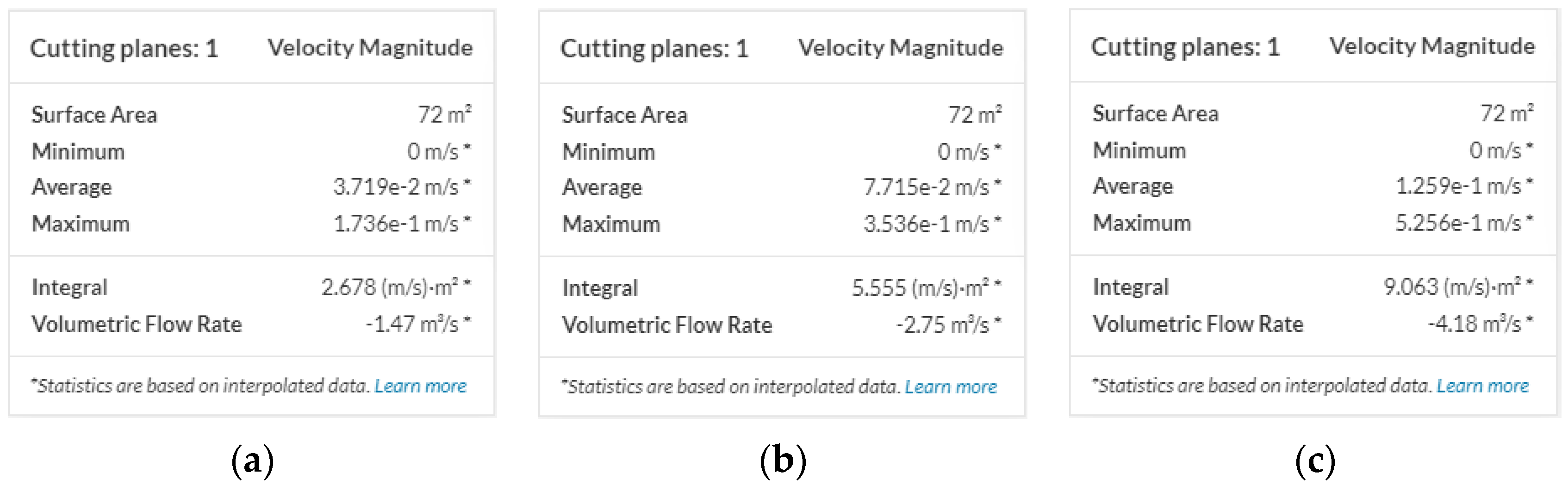
| Air Exchanges Per Hour, n [h−1] | Average Air Velocity inside the Building, vair,int,avg [m/s] |
|---|---|
| 3 | 0.037 |
| 6 | 0.077 |
| 9 | 0.107 |
| Specifics | Continental Climate | Maritime Climate | ||
|---|---|---|---|---|
| Case 1a | Case 2a | Case 1b | Case 2b | |
| Heat recovery | Yes | Yes | − | − |
| Natural night ventilation | − | Yes | − | − |
| Specific cooling energy need, Q”C,nd [kWh/(m2 a)] | 66.41 | 37.48 | 53.38 | 36.18 |
Publisher’s Note: MDPI stays neutral with regard to jurisdictional claims in published maps and institutional affiliations. |
© 2022 by the authors. Licensee MDPI, Basel, Switzerland. This article is an open access article distributed under the terms and conditions of the Creative Commons Attribution (CC BY) license (https://creativecommons.org/licenses/by/4.0/).
Share and Cite
Veršić, Z.; Binički, M.; Nosil Mešić, M. Passive Night Cooling Potential in Office Buildings in Continental and Mediterranean Climate Zone in Croatia. Buildings 2022, 12, 1207. https://doi.org/10.3390/buildings12081207
Veršić Z, Binički M, Nosil Mešić M. Passive Night Cooling Potential in Office Buildings in Continental and Mediterranean Climate Zone in Croatia. Buildings. 2022; 12(8):1207. https://doi.org/10.3390/buildings12081207
Chicago/Turabian StyleVeršić, Zoran, Marin Binički, and Mateja Nosil Mešić. 2022. "Passive Night Cooling Potential in Office Buildings in Continental and Mediterranean Climate Zone in Croatia" Buildings 12, no. 8: 1207. https://doi.org/10.3390/buildings12081207