Article

Deformation Characteristics and Optimization Design for Large-Scale Deep and Circular Foundation Pit Partitioned Excavation in a Complex Environment

1
School of Civil Engineering, Beijing Jiaotong University, Beijing 100044, China
2
Key Laboratory of Track Engineering Beijing, Beijing 100044, China
3
Shanghai Road and Bridge Group Co., Ltd., Shanghai 200433, China
4
Shanghai Engineering Research Center of Green Pavement Materials, Shanghai 200433, China
*
Authors to whom correspondence should be addressed.
Buildings 2022, 12(9), 1292; https://doi.org/10.3390/buildings12091292
Submission received: 21 June 2022 / Revised: 9 August 2022 / Accepted: 11 August 2022 / Published: 23 August 2022
(This article belongs to the Section Architectural Design, Urban Science, and Real Estate)

Abstract

:
With the rapid development of urban rail transit, the impact of the construction of large-scale deep and circular foundation pits (LDCFPs) on the surrounding environment has become increasingly prominent; however, there is no definite standard for the design theory and construction method of the retaining structure of LDCFPs; therefore, the such standard needs further research and exploration. The paper is based on the LDCFP engineering of a subway station in Wuhan, China. Two partitioned excavation methods (step-by-step and synchronous excavation) of LDCFP were discussed by numerical simulation; the deformation characteristics of the soil around the foundation pit, the lateral deformation of the retaining structure in each partitioned district, and the distribution of the supporting axial force were analyzed; the deformation law of LDCFP was revealed; and the safe and economic excavation method was determined. The field monitoring test was carried out to reveal the deformation characteristics and stress evolution behavior for the supporting structure of the LDCFP in the subway station. It was concluded that the construction method of synchronous partitioned excavation in the same layer is more conducive to controlling the overall deformation, with the deformation of the circular retaining structure being uniform and the “vault effect” of the circular retaining structure having a certain constraint on the deformation of the foundation pit. The research results can provide guidance for the design and construction of supporting engineering and similar engineering.

1. Introduction

With the continuous progress of urbanization, the development of urban underground space in China is continuously evolving from point-line planes to blocks and networking [1,2,3], which shows the characteristics of a larger spatial scale, longer structural span, deeper underground structure, complex foundation pit support, and more excavation steps [4,5,6].
Foundation pit engineering is an important part of urban underground space in construction. It usually relies on temporary or permanent support structures to bear the surrounding soil pressure and finally form a safe and reliable underground space. In the process of deep foundation pit construction, engineering accidents frequently occur for many reasons, such as construction technology and management. The deformation behavior, reinforcement, and support measures of deep foundation pits during excavation were studied by an increasing number of scholars [7,8,9,10]. Houhou [11] and Teparaksa [12] analyzed the whole construction process of deep foundation pits in clay layers using numerical simulations and studied the characteristics of surface settlement and the deformation behavior of supporting structures. Yajnheswaran et al. [13] studied the supporting and displacement control effect of deep foundations by pit anchor bolts. Cui et al. [14] analyzed the surface settlement and horizontal displacement caused by deep foundation pit excavation and predicted the location of the maximum displacement. At present, the construction of urban underground space with “multidimensional space, large scale, and complex structure” has become an inevitable development trend [15,16]. The new construction concept puts forward higher requirements for the construction of foundation pit engineering, especially the construction of high standard special-shaped deep and large foundation pit engineering, which is particularly challenging [17].
Research on foundation pit engineering mostly focuses on normal shape foundation pits, such as rectangular and long strip shapes. During this period, to alleviate the contradiction between urban land supply and demand, protect underground pipelines and surrounding buildings, and make full and rational use of the existing land, various unconventional-shaped deep and large foundation pits will inevitably appear in the construction of subway stations [18,19]. At present, there are few studies on the deformation characteristics, support measures, and stress evolution process of various unconventional-shaped deep and large foundation pits, such as LDCFPs. Because the circular foundation pit has special spatial stress characteristics, it can give full play to the characteristics of strong compressive capacity under the action of axial load. It has the advantages of large stiffness, small wall deformation, and convenient mechanized operation of LDCFP [20,21], such as the LDCFP engineering of the Shanghai global financial center and the Wuhan Optics Valley Plaza complex project in China. Some results were obtained from research on LDCFP, including field monitoring [22,23], numerical simulation [24,25], and theoretical solutions [26,27]. For example, Tobar [28], Cheng [29], and other scholars proposed the circumferential stress coefficient, and it is suggested to take the static earth pressure coefficient as the circumferential stress coefficient. Tan et al. [30] studied the performance of medium and large circular foundation pits excavated in clay gravel pebble mixed strata and analyzed the influence of foundation pit excavation on the surrounding environment. However, the circular foundation pit was mainly subjected to circumferential axial pressure; its deformation is mainly composed of circumferential compression deformation, mud compression in the groove section, and asymmetric load; and the LDCFP is very sensitive to inhomogeneous load [31,32]. Therefore, the symmetry of the circular foundation pit between earth pressure and horizontal deformation is particularly important in the construction period. There is a lack of sufficient understanding of the deformation characteristics and the impact on the surrounding environment caused by the excavation of circular foundation pits, and it is also the main technical obstacle to realizing the best engineering design and construction of circular foundation pits.
At present, the foundation pit engineering of urban subways is usually located in the dense areas of buildings and urban lifeline engineering [33,34], which puts forward higher requirements for the supporting structure and excavation sequence of LDCFPs. Therefore, the paper is based on the LDCFP engineering of a subway station in Wuhan, China. The deformation characteristics of two partitioned excavation methods (step-by-step and synchronous excavation) of LDCFP were discussed by numerical simulation, and the reasonable excavation method was determined. The field monitoring test was carried out to reveal the deformation characteristics and stress evolution behavior for the supporting structure of the LDCFP in the subway station, and economical and effective control measures were proposed to provide guidance for the design and construction of the engineering and another similar engineering.

2. Project Overview

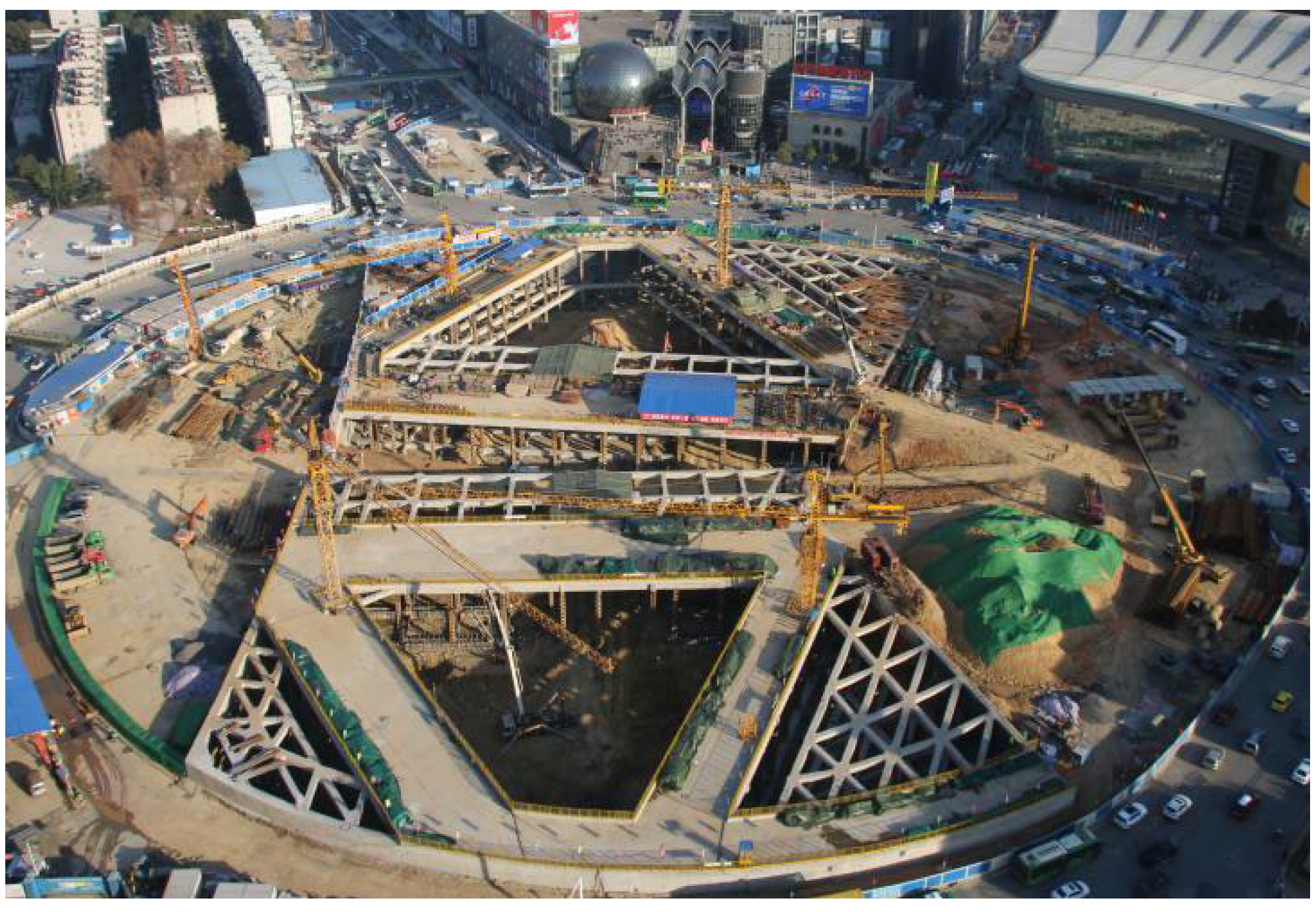
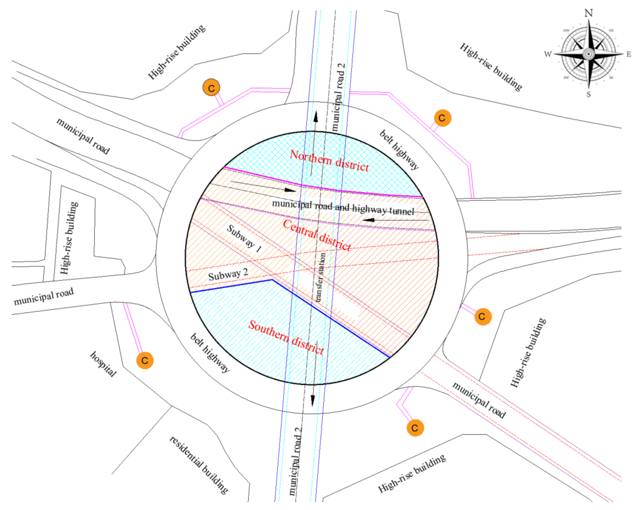
2.1. Project Overview and Surrounding Environment

The paper is based on the LDCFP engineering of a subway station in Wuhan, China. The project includes rail transit engineering, municipal engineering, and underground public space, and the surrounding environment of the foundation pit is complex. High-rise buildings, pedestrian crossing channels, and urban transportation are distributed around the foundation pit (as shown in Figure 1). Therefore, the stability requirements of the foundation pit engineering are higher.
LDCFP engineering mainly includes three layers of underground structures. The first underground layer is the subway station hall and underground public space, and the first underground layer contains the mezzanine structure, which is the platform of the subway transfer station passing through a highway tunnel. The second underground layer is the subway transfer hall and equipment room, which passes through another highway tunnel. The third underground layer is the platform floor of another subway station. During the construction of the foundation pit, the geological environment varies greatly, the surrounding environment of the foundation pit is complex, and the traffic flow is large. Therefore, ensuring the construction safety of foundation pits, reducing the impact of construction on surrounding buildings, and maintaining the continuous flow of road traffic are difficult tasks for LDCFP engineering construction.
The LDCFP engineering mainly adopts a multi-span frame structure with three underground layers; the buried depth of the baseboard on the first underground layer is 14 m, the buried depth of the baseboard on the second underground layer is 21 m, the third underground layer is typical pit-in-pit engineering, and the maximum depth is 33 m. The plane diameter of the LDCFP engineering is 200 m, and the surrounding environment of the LDCFP engineering is shown in Figure 2.

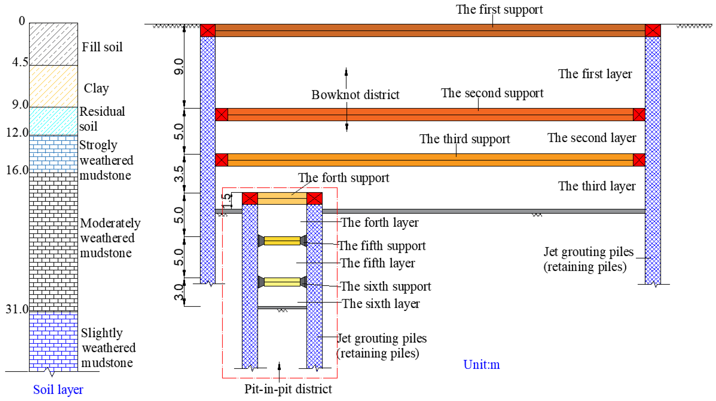
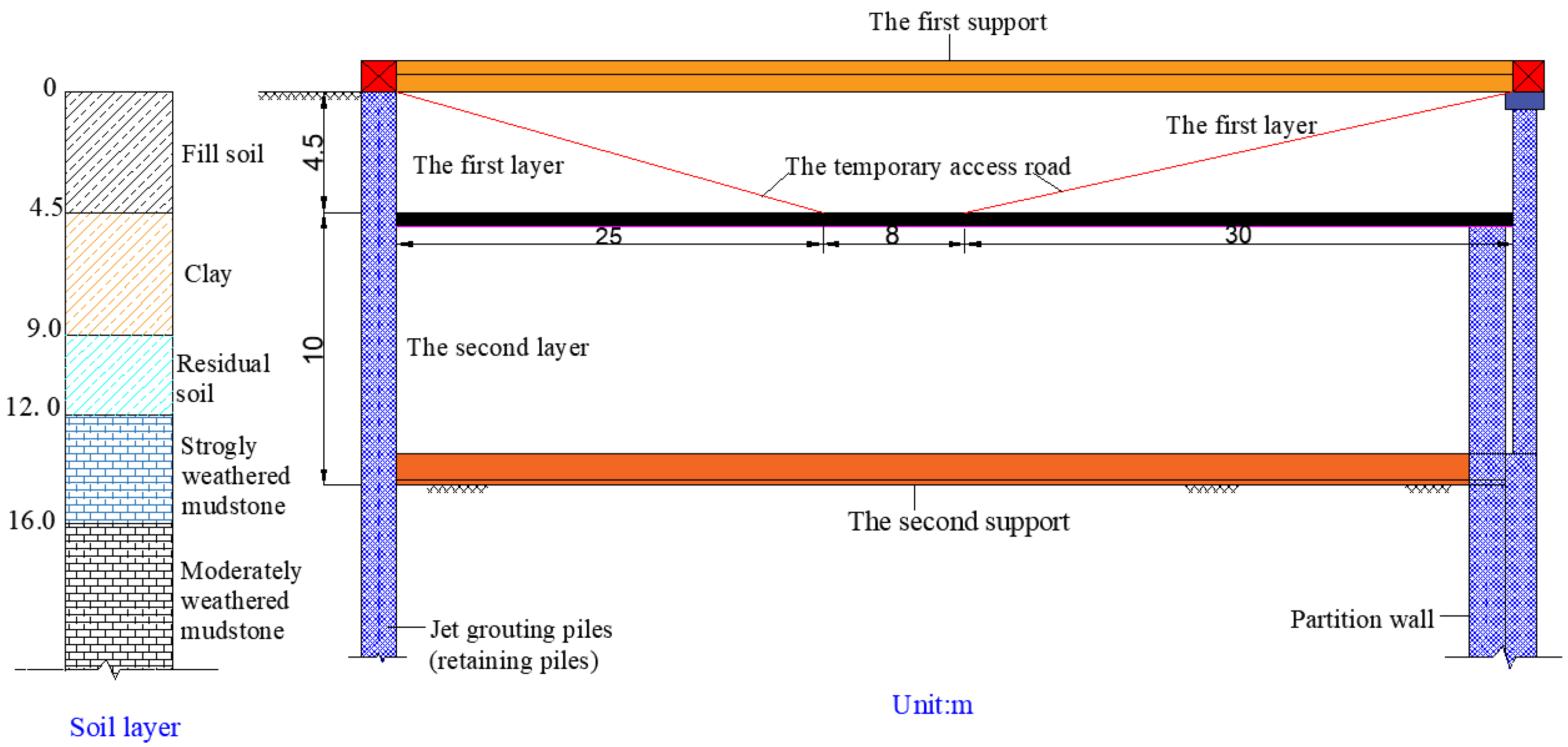
2.2. Overview of Engineering Geology

According to the engineering exploration of LDCFP engineering, it is divided into five layers from top to bottom based on the stratum lithology and characteristics. The soil parameters are determined according to the engineering investigation and geotechnical test; the soil layer parameters of the foundation pit engineering are shown in Table 1. The stagnant water level in the upper layer of the foundation pit is 1.20–5.30 m below the ground, and the static water level is 0.3–3.0 m below the ground. The reason for the large range of these water levels is that the monitoring time is just at the time of more rainfall.

2.3. Design of Foundation Pit Supporting Structure

According to the geological conditions and surrounding environment of foundation pit engineering, the supporting structure adopted by the foundation pit includes retaining piles, supports of each layer, column piles, top beams, and wai purlins.

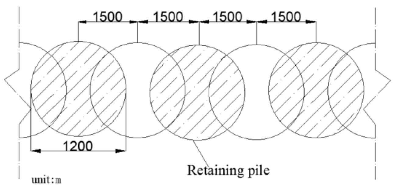
2.3.1. Design of Retaining Piles

The foundation pit is supported by bored piles and constructed by the open excavation method. The rotary drill is used to complete the pile drilling, and the impact drill is used to form the hole in the limited area. In the foundation pit engineering, retaining piles with a diameter of φ1200@1500 mm are used for the supporting structure. There are more than 3400 retaining piles in total, and the slurry is used for wall protection. A schematic diagram of the retaining piles is shown in Figure 3.

2.3.2. Supports of Each Layer Design

Supports Design in the Central District of LDCFP

The central district of the foundation pit is designed as three layers underground structure, and the maximum excavation depth is 33 m. The first and second layers of the underground structure are defined as the bowknot district, and the third layer is the long-shaped excavation of the foundation pit (that is, pit in pit district). The soil layer is divided into six layers according to the altitude of support during excavation. The profile of the foundation pit support is shown in Figure 4.

Supports Design in the Northern and Southern Districts of LDCFP

Both the southern and northern districts of the foundation pit are two layers of underground structures. The first layer (the soil layer between the first support and the second support) is approximately 4.5–5 m deep and is constructed in two steps. The second layer (the soil layer between the second support and the bottom layer) is approximately 9–10 m deep and is constructed in two steps. The profile of the foundation pit support is shown in Figure 5.

3. Finite Element Simulation Analysis

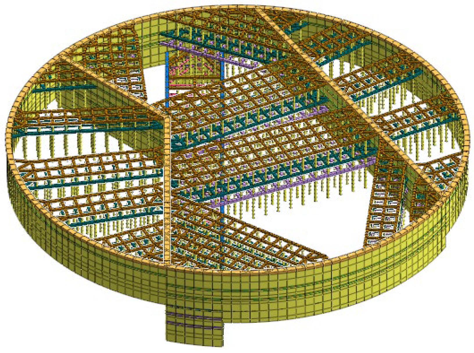
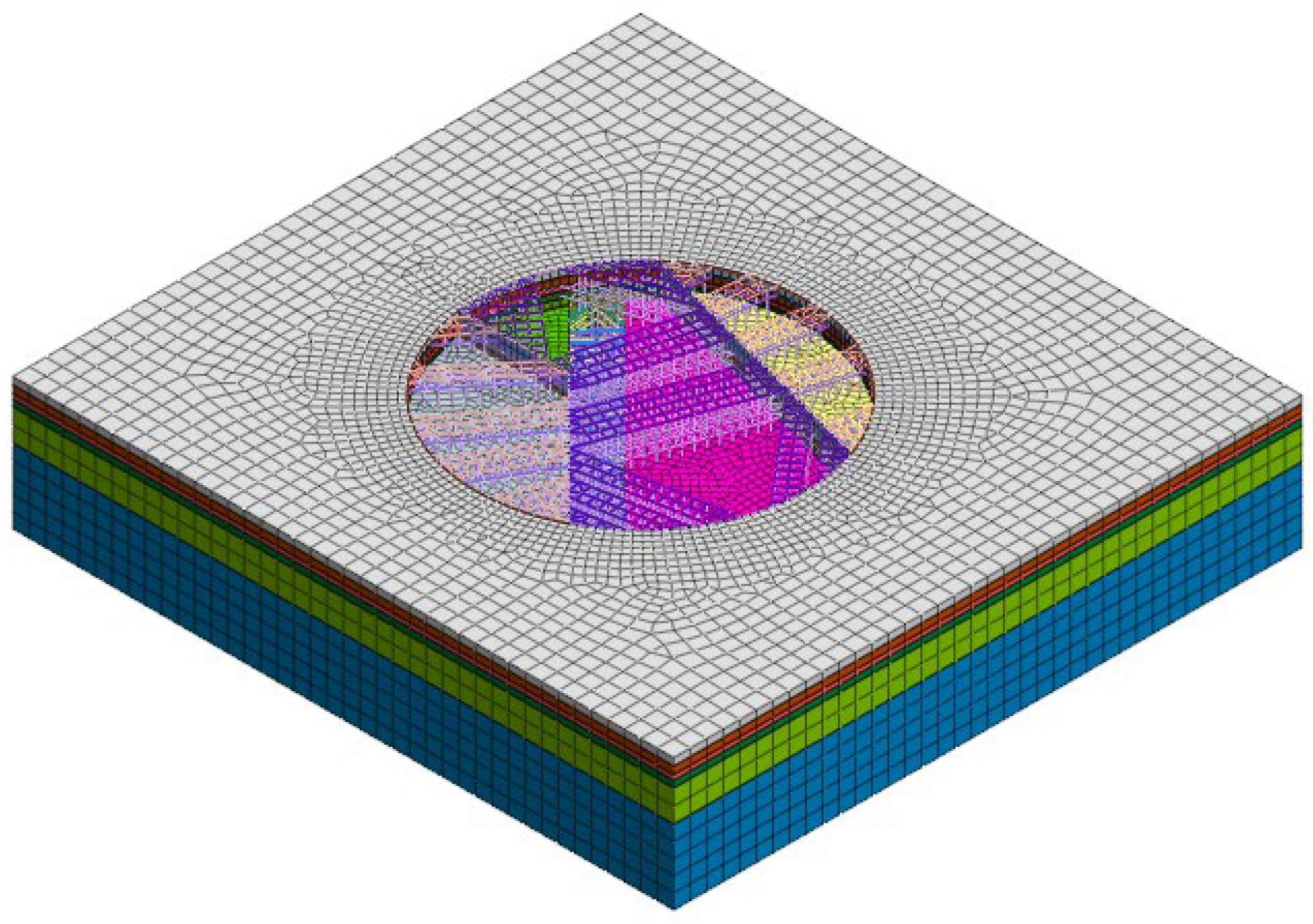
3.1. Model Establishment

In this paper, Midas/gts software was used for numerical simulation, and the model was established by spatial strain. The geometric model was established according to the engineering geological data, including the central district, the northern district, and the southern district of the foundation pit. The foundation model in the central district was established according to the support design, and the excavation was divided into 6 layers, with depths of 9 m, 5 m, 6 m, 4 m, 5 m, and 4 m. The foundation pit in the northern and southern districts is 14 m deep and was excavated in two layers, with excavation depths of 4.5 m and 8.5 m, respectively. Since the influence range of the foundation pit construction is approximately 2–3 times the plane size of the foundation pit, the model size is 400 m × 400 m × 100 m.
The self-weight load of the structure was considered in this model, and the direction of the load was vertically downward. The boundary conditions in the model are automatically constrained; that is, the normal horizontal displacement is constrained around the model, the displacement in three directions (x, y, z) is constrained at the bottom of the model, and the earth’s surface is a free surface. At the same time, the vertical torsional restraint is set at the bottom of the column piles. Assuming that the soil load is uniformly distributed, the overburden load of the surrounding main roads was designed to be 15 kN/m2, and the surrounding building load was accumulated according to 18 kN/m2 per layer.
The modified Mohr–Coulomb model was adopted for the constitutive relationship of the soil layer. The tangent modulus Et of stress–strain is [35],
E t = 1 R f 1 sin φ σ 1 σ 3 2 c cos φ + 2 σ 3 sin φ 2 E 0
where Et is the tangent modulus, E0 is the initial modulus of elasticity, Rf is the failure ratio, and its value is between 0.75 and 1.00, c is cohesion, and φ is the angle of internal friction. σ1, σ2, and σ3 are the stresses of the soil.

3.2. Model of Supporting Structure

In the model, the retaining pile was transformed into an underground diaphragm wall in the way of equal stiffness [36], and the linear elastic model plate element with a thickness of 965 mm was used for simulation. The transformed formula is shown in Equations (2) and (3),
1 12 ( D + t ) h 3 = 1 64 π D 4
h = 0.838 D 3 1 1 + t D
where D is the diameter of the retaining pile, t is the spacing of the retaining piles, and h is the thickness of the transformed underground diaphragm wall.
Six supporting structures were set in the central district of the foundation pit along the depth direction. The first to fourth supporting structures were reinforced concrete supports, and the fifth and sixth supporting structures were steel pipe supports. Two concrete supporting structures were set along the depth direction in the northern and southern districts of the foundation pit, and top beams or enclosure beams were set at the ends of the supporting structures. Supports of each layer, column piles, top beams, and wai purlings were simulated by linear elastic beam elements, and the material parameters of the supporting structure are shown in Table 2. The model grid of the supporting structure is shown in Figure 6.
When the model was established, 10-node and tetrahedron elements were used for the soil layer, 3-node line element was used for the beam, and 12-node interface elements were used for the interaction of soil and structure in the process of grid division. The total number of model elements was 360,437, and the total number of nodes was 263,819. The solution type of the model was the construction stage. The model is shown in Figure 7.
Figure 6. The model grid of the supporting structure.
Buildings 12 01292 g006
Figure 7. Three-dimensional finite element model of the LDCFP.
Buildings 12 01292 g007
During the construction of the foundation pit, the geological environment varies greatly, the surrounding environment is complex, and the traffic flow is large. The construction method of partitioned excavation should be adopted for LDCFP engineering. In order to study the interaction between various districts under different excavation procedures, different construction organizations of foundation pit excavation were simulated from the two aspects of step-by-step and synchronous excavation, and the deformation characteristics of the foundation pit excavation were discussed.

4. Results of Numerical Simulation

4.1. Deformation Characteristics of Step-By-Step Partitioned Excavation

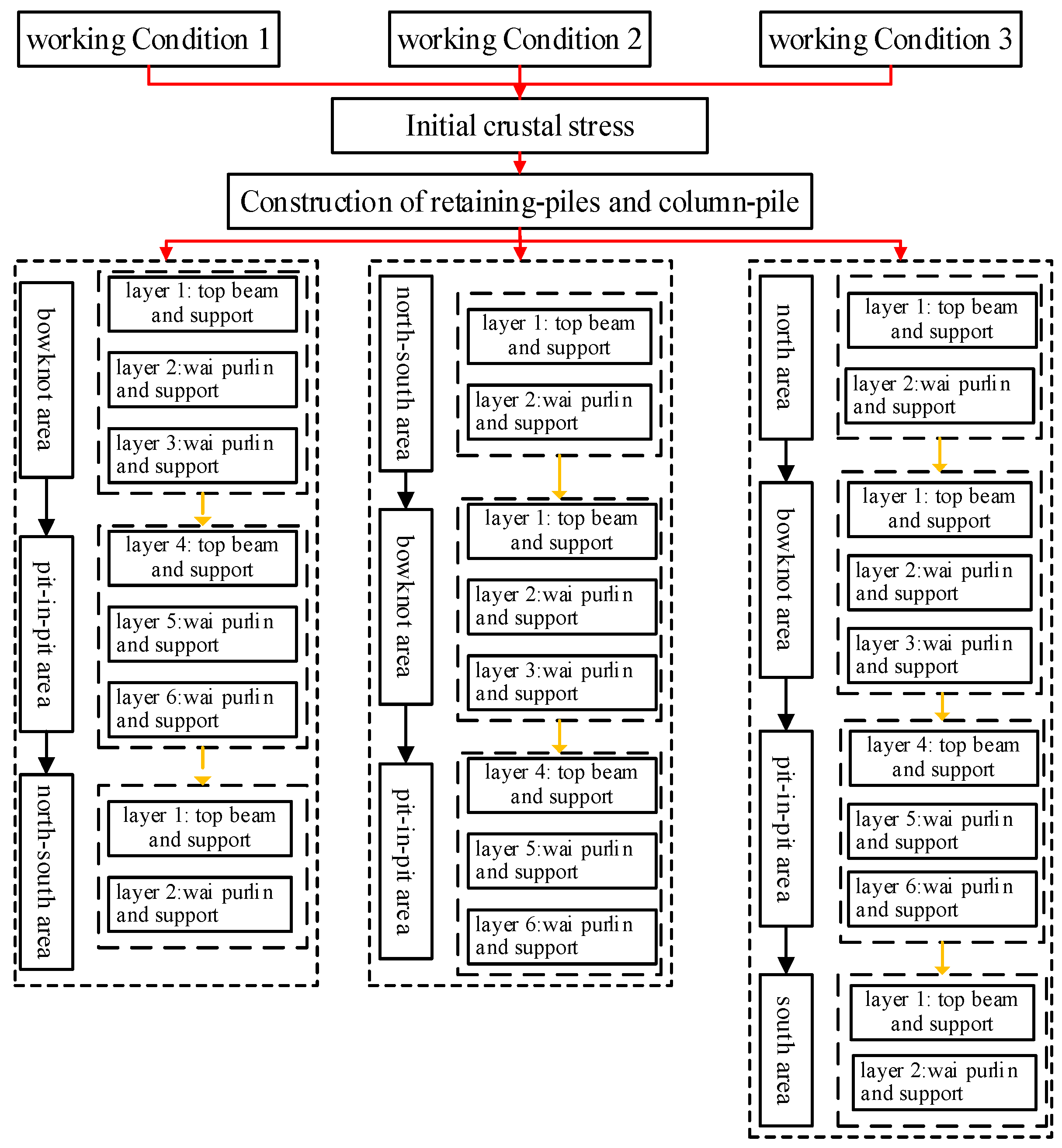
4.1.1. Model Working Conditions Design

Three working conditions of the step-by-step partitioned excavation method were simulated. (1) The central district of the foundation pit was excavated first, and then the southern and northern districts were excavated at the same time, which was recorded as condition 1. (2) The southern and northern districts of the foundation pit were excavated at the same time, and then the central district of the foundation pit was excavated, which was recorded as condition 2. (3) The northern district of the foundation pit was excavated first, then the central district of the foundation pit, and finally the southern district of the foundation pit, which was recorded as condition 3. The analysis steps of each working condition are shown in Figure 8.

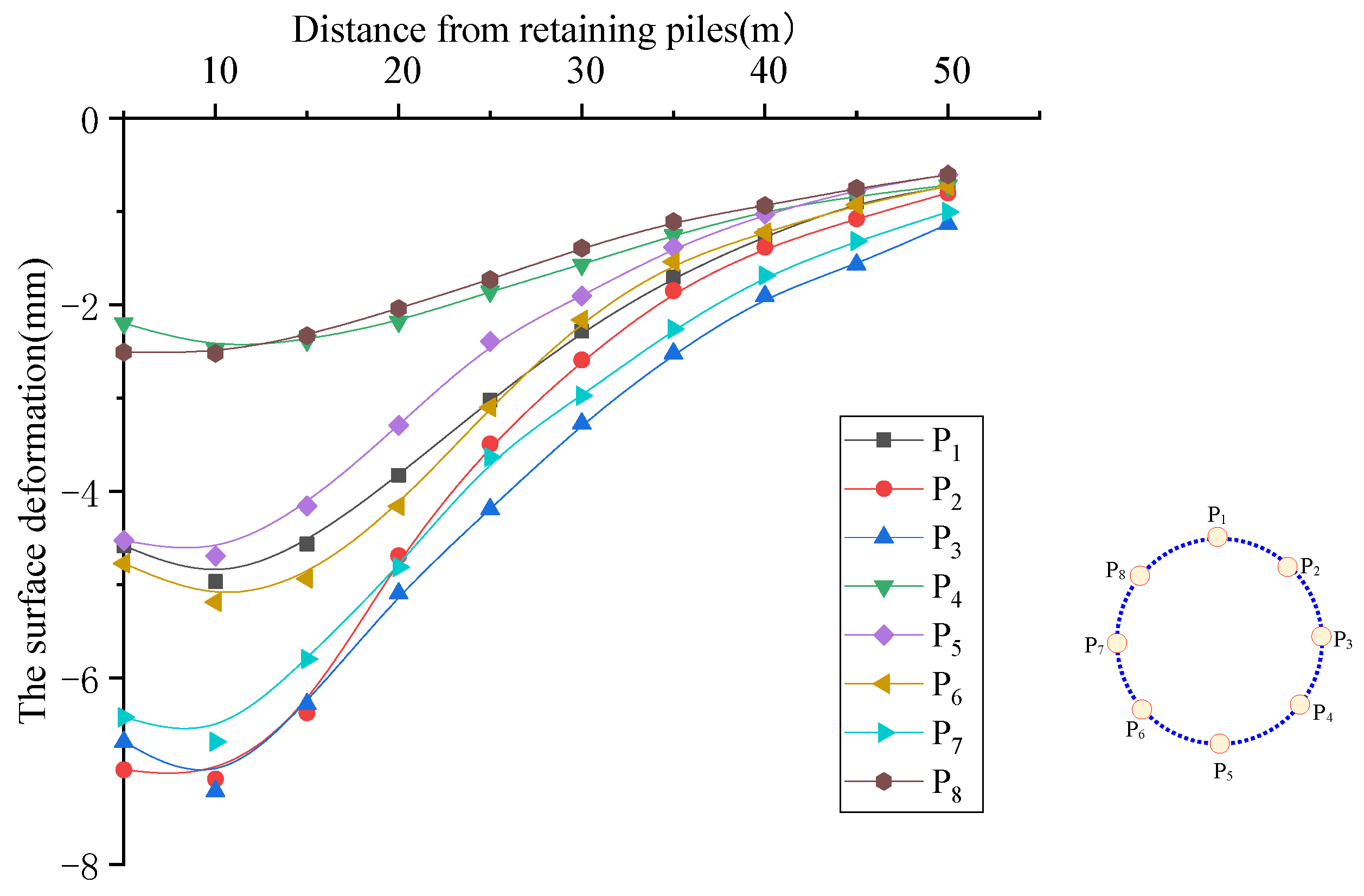
4.1.2. The Deformation Characteristics of the Ground Surface around the Foundation Pit

In order to study the deformation characteristics of the ground surface around the foundation pit, modeling and calculation were carried out according to the above working conditions, and the measuring point was selected in the eight directions of the foundation pit; it was named P1-P8 clockwise from due north. The surface deformation within 50 m of the retaining piles was analyzed. By taking work Condition 1 as an example, the surface deformation characteristics around the foundation pit are shown in Figure 9. The maximum deformation of three working conditions is shown in Figure 10.
Figure 10 shows that the maximum deformation of three working conditions is working Condition 3 > working Condition 2 > working Condition 1. This is because the symmetrical excavation method was adopted for Conditions 1 and 2, and the spacing effect of the foundation pit was used.

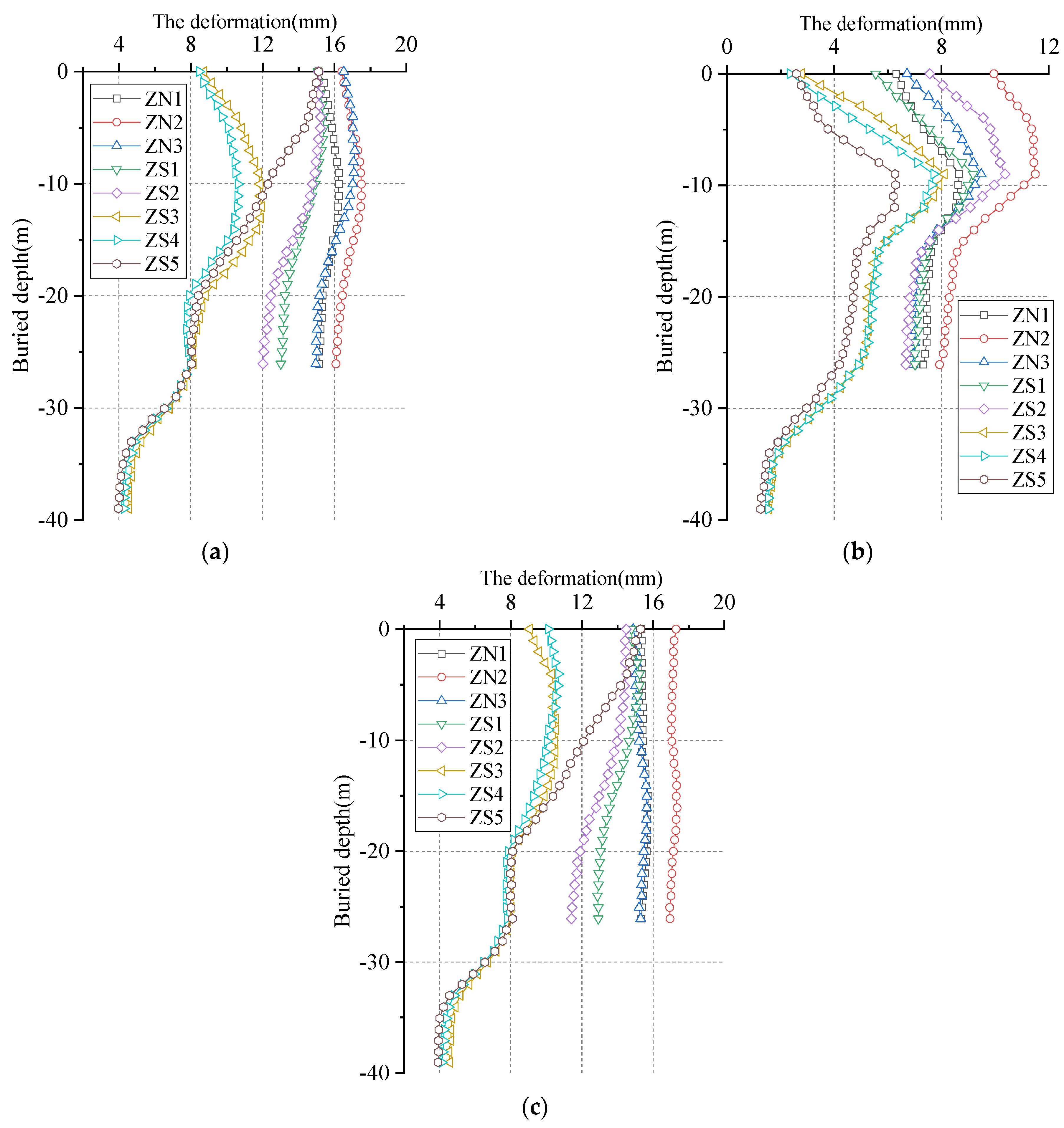
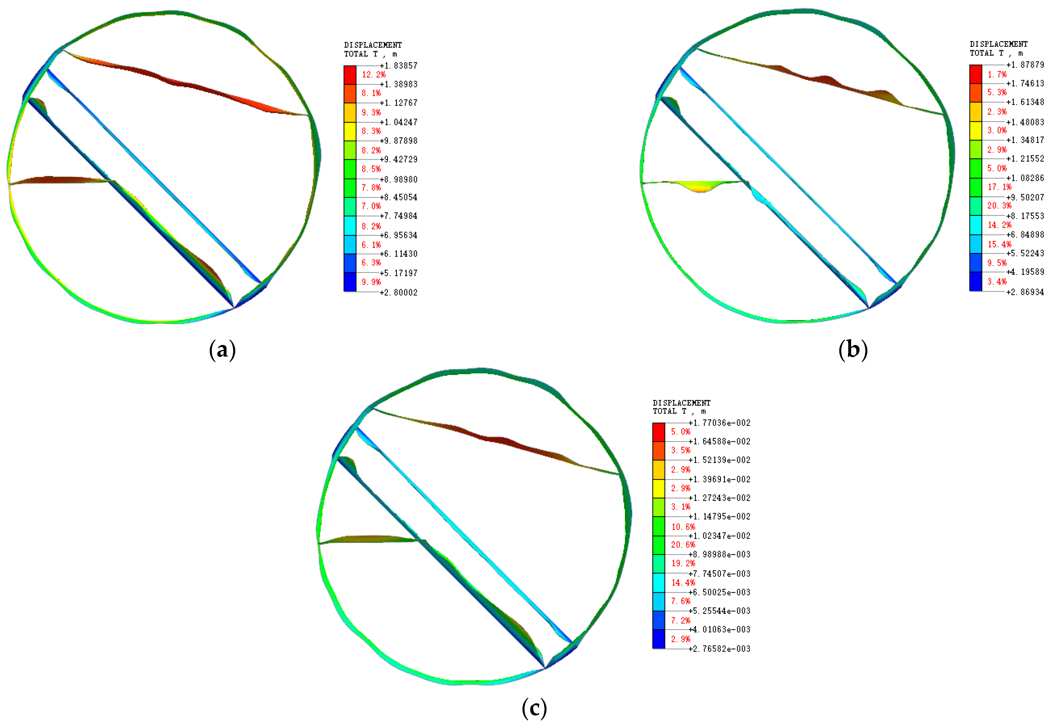
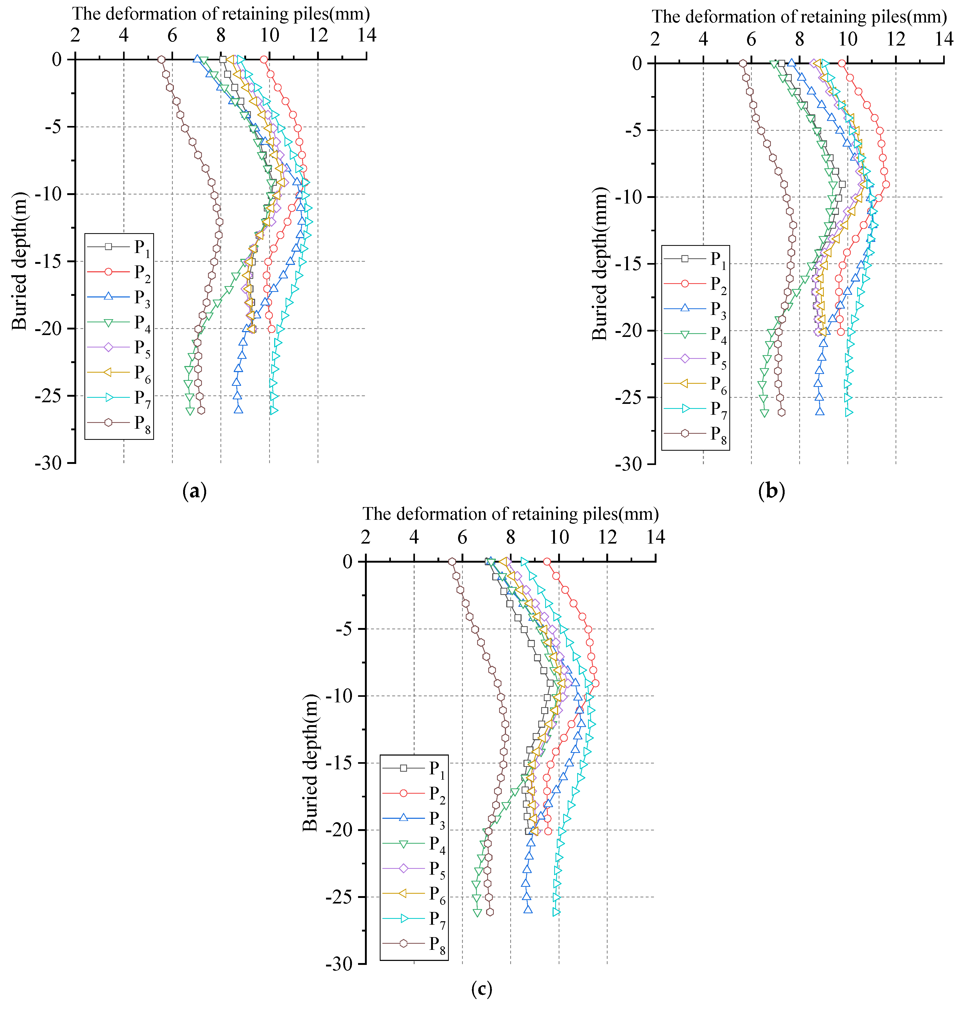
4.1.3. Deformation of Supporting Structure

After the numerical calculation of the model is completed according to the excavation steps, the deformation nephogram of the supporting structure is shown in Figure 11.
The deformation nephograms of the supporting structure under three working conditions were compared, and it can be seen that the deformation difference of the supporting structure is obvious. The difference is mainly reflected in the shared retaining piles of the central and southern–northern districts. Under condition 1, the shared retaining piles by the south–north rows were all deformed to the inner side of the central district; under Condition 2, part of the shared retaining piles by the south–north rows were deformed to the outside of the central district; under Condition 3, part of the shared retaining piles by the north row deformed to the outside of the central district, and part of the shared retaining piles by the south row deformed to the inside of the central district. The deformation nephogram shows that the final deformation of the shared retaining pile is related to the excavation sequence of the foundation pit.

Deformation of the Exterior Retaining Structure

The deformation of retaining piles in each district under the working condition of the step-by-step partitioned excavation method was further analyzed. The deformation of the retaining piles in the excavation process of the foundation pit is shown in Figure 12.
The deformation law of the exterior retaining pile under each working condition is basically consistent, and the pile shaft was “waist drum shaped”; except for measuring point P1, the deformation of all retaining piles was concentrated in the range of 7–11 mm. The above analysis showed that the deformation law of the exterior retaining structure is less affected by the excavation sequence in different districts of the foundation pit, and the deformation of the exterior retaining structure is relatively uniform.

Retaining Structure Deformation in the Pit-in-Pit District

Three reference points of retaining piles were selected along with the equal distance to the north side of the foundation pit, which denotes K1 (west side pit angle), K2, and K3 (east side pit angle). Two reference points of the retaining piles were selected along with the equal distance of the south side of the foundation pit, which denotes K4 (west side pit angle) and K5 (short side midpoint). The final deformation of the retaining structure in the pit-in-pit district is shown in Figure 13.
Figure 13 shows that:
(1) The K1, K3, and K4 measuring points have almost no difference in the deformation of the pile shaft under different excavation steps. The maximum deformation at the top of the pile is concentrated in the range of 4–5 mm, and the deformation decreases gradually with increasing excavation depth;
(2) By comparison, it was found that the deformation of the retaining piles under Condition 2 is small. This is because when the pit-in-pit district is excavated, the soil in the northern and southern districts is excavated. Due to the unloading effect of the soil, the load effect of the upper soil in the pit-in-pit district is weakened, so the deformation is small. The excavation sequence of the foundation pit has a certain influence on the deformation of the retaining piles in the pit-in-pit district;
(3) Deformation of the shared retaining structure
The shared retaining structure of LDCFP refers to the retaining piles used to separate the central district and the northern–southern districts. There are three rows of shared retaining piles in this engineering. The north row is located on the north side of the bowknot district (the length is 26 m), the south-1 row is located on the southwest side of the bowknot district (the length is 26 m), and the south-2 row is located in the southeast side of the bowknot district (the length is 39 m). Three reference points were selected along the north row, which denote ZN1 (1/4 side), ZN2 (midpoint), and ZN3 (3/4 side). Five reference points were selected along the south-1 and south-2 rows, which denote ZS1 (1/3 south-1 row), ZS2 (2/3 south-1 row), ZS3 (1/4 south-2 row), ZS4 (south-2 row midpoint), and ZS5 (3/4 south-2 row). The deformation of each reference point in the construction stage of the bowknot district, pit-in-pit district, and northern–southern districts is shown in Figure 14.
Figure 14 shows that:
(1) In the excavation process of the bowknot district, the deformation of shared retaining piles shaft is approximately a “waist drum-shaped”. The deformation is mainly concentrated 10 m underground, and the deformation of the pile shaft below 10 m gradually decreases. The deformation of the retaining pile in the center is greater than that of the retaining piles on both sides;
(2) When the pit-in-pit district is excavated, the deformation of the bottom of the retaining piles (long piles) in the south-2 row continues to increase, and the maximum deformation position gradually moves down with the excavation;
(3) When the foundation pit is constructed in the northern and southern districts, the deformation of the short pile shaft changes from the original “waist drum shaped” to the approximate “vertical shaped”, due to the unloading effect of the soil behind the pile, and the pile shaft is mainly affected by the axial force of the support in the foundation pit;
(4) The deformation of the retaining piles mainly occurs in the excavation stage of the northern–southern districts.
Figure 14. Deformation of the shared retaining structure. (a) working Condition 1. (b) working Condition 2. (c) working Condition 3.
Buildings 12 01292 g014

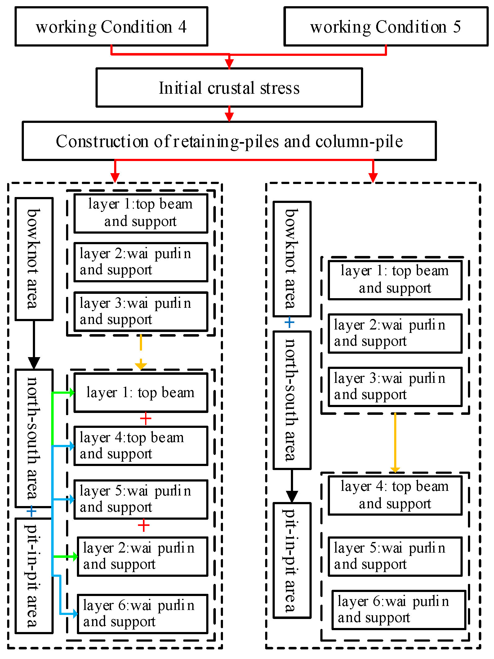
4.2. Deformation Characteristics of Synchronous Partitioned Excavation

4.2.1. Design of Model Working Conditions

The synchronous partitioned excavation of the central district and the northern–southern district of the foundation pit is divided into two cases: synchronous excavation of the same layer and the layered synchronous excavation. The construction steps for each condition are shown in Figure 15.

4.2.2. The Deformation Characteristics of the Ground Surface around the Foundation Pit

The modeling and calculation were carried out according to the above working conditions. After the calculation of the foundation pit model, the reference point was selected at the same position as the previous working condition, which is denoted as M1–M8. The deformation characteristics of the ground surface around the foundation pit are shown in Figure 16.
The deformation characteristics of the surface deformation of the ground surface around the foundation pit under Conditions 4 and 5 are basically the same. Because of the symmetrical partitioned excavation method was adopted in both conditions.

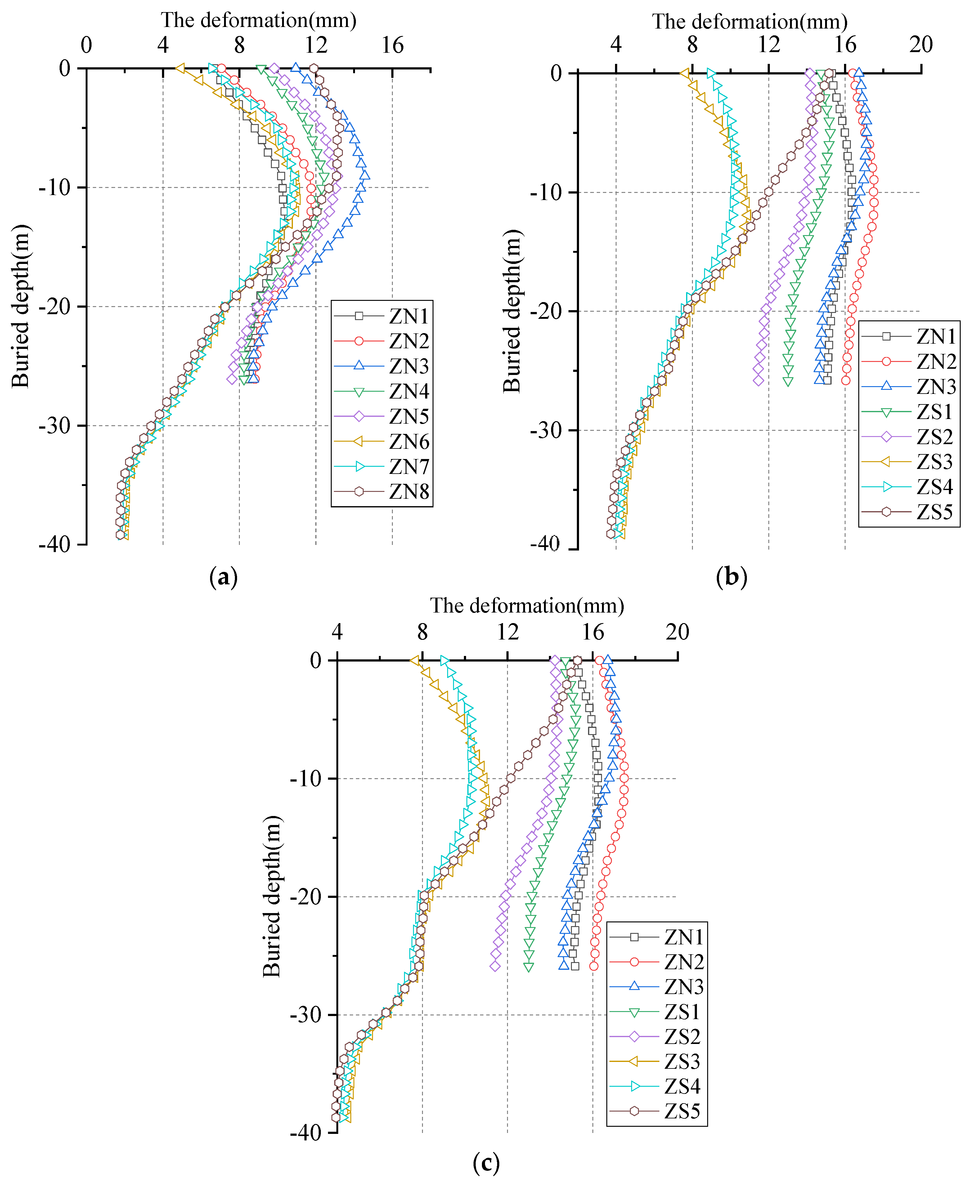
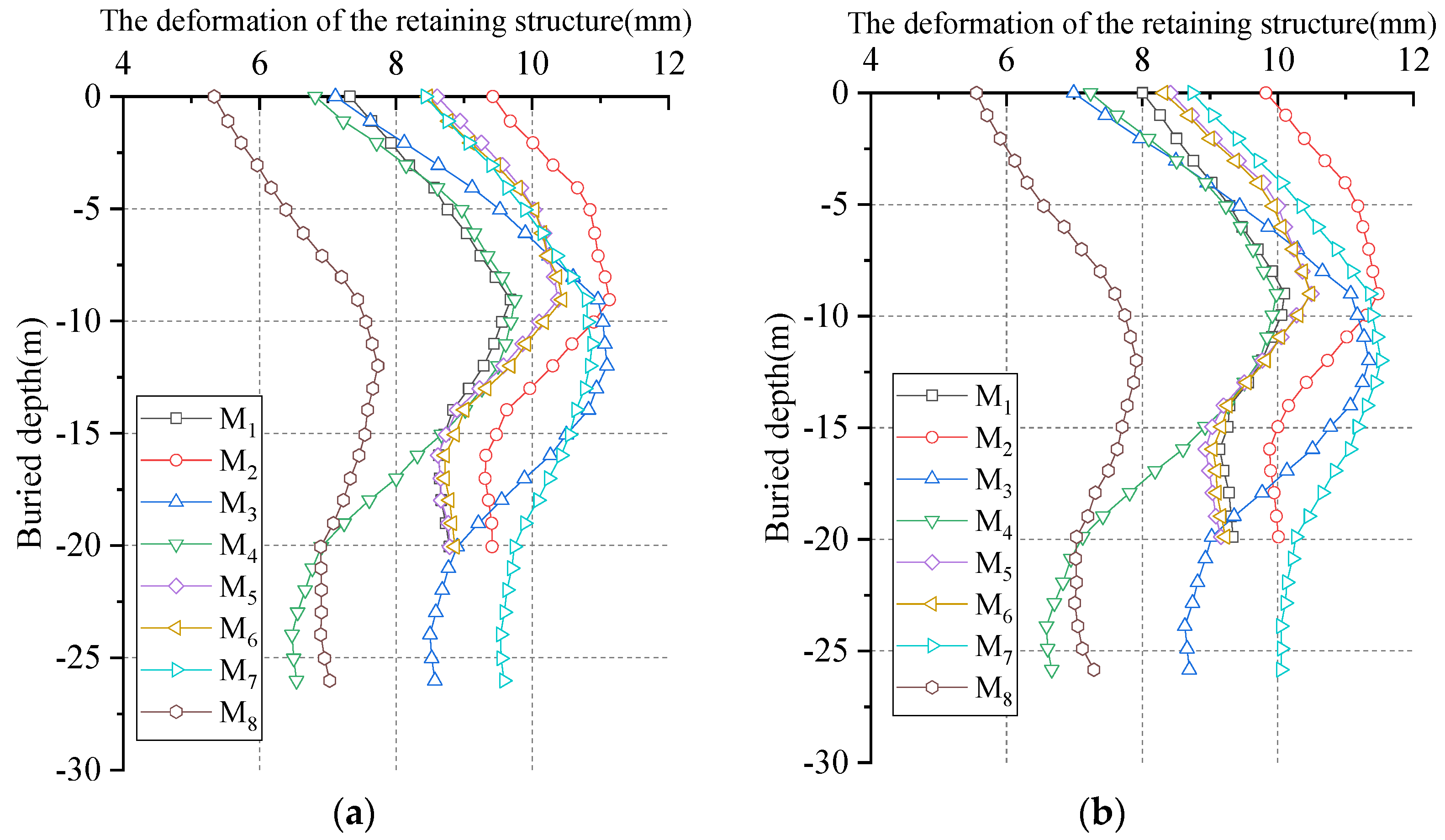
4.2.3. Deformation of Retaining Structure

When the calculation was completed according to the excavation steps of working Conditions 4 and 5, the deformation of the retaining structure was analyzed.

Deformation of Exterior Retaining Structure

The deformation of the retaining structure during the synchronous partitioned excavation was analyzed, as shown in Figure 17.
The deformation curve shows that under the condition of synchronous excavation in different districts, the deformation of the surrounding retaining pile was not affected by the excavation process, and the deformation is relatively uniform.

Deformation of the Retaining Structure in the Pit-in-Pit District

Five reference points were selected with the same location as the step-by-step partitioned excavation, named M1′, M2′, M3′, M4′, and M5′. Under working Conditions 4 and 5, the deformation of retaining piles is shown in Figure 18 after the synchronous excavation in different districts was completed.
Figure 18 shows that the deformation of the retaining pile in the pit-in-pit district is consistent with the final deformation of the step excavation, indicating that the synchronous excavation sequence of the foundation pit has little effect on the deformation of the retaining pile in the pit-in-pit district.

Deformation of the Sharing Retaining Structure

Eight reference points were selected with the same location as the step-by-step partitioned excavation. The deformation of each retaining pile at different excavation stages was analyzed, as shown in Figure 19.
Figure 19 shows that under working Condition 4:
(1) When the excavation of the first layer is completed, the deformation of the top retaining pile is small under the constraint of the first and second supports, and the maximum deformation of the pile shaft is located approximately 10 m underground; that is, between the second support (−4 m) in the northern–southern districts and the bottom (−14 m) in the northern–southern districts;
(2) When the LDCFP is excavated to the first layer in the central district, due to the unloading effect of the foundation pit soil behind the pile, which is approximately linear-shaped, showing the rebound deformation of the retaining pile shaft. There is no obvious deformation of the pile top, which is due to the concrete support erected before excavation hindering the rebound of the retaining pile;
(3) When the LDCFP is excavated to the third layer in the central district, the deformation of each retaining pile further increases and the deformation of the pile shaft is the most obvious in the range of 10–20 mm; in the excavation of the pit-in-pit district, only the ZS4 and ZS5 retaining piles (long piles) continue to deform downward.
Figure 20 shows that under Condition 5:
(1) When the foundation pit is excavated in the bowknot district, the shared retaining pile is only subjected to unilateral earthwork unloading, and the deformation trend of the retaining pile in each district is relatively close, indicating that the stress of the retaining pile in each district is consistent;
(2) In the early stage of excavation, due to the unloading effect of the soil behind the pile, the overall deformation of the retaining pile decreases when the southern and northern districts of the foundation pit are excavated simultaneously. With the advance of excavation steps, the deformation of the retaining structure continues to increase, which is manifested as large deformation of short piles as a whole, and obvious deformation of long piles only occurs at the upper part of the pile shaft;
(3) When the foundation pit excavation is completed, the deformation of the long pile is parabolic-shaped, and the short pile still has a certain drum-shaped; that is, the deformation of the retaining pile is not fully restored, and the overall deformation of the retaining pile is larger, and the top deformation of ZS5 is larger than that of ZS3 and ZS4, which is related to the stiffness of the corner brace. This shows that the internal force changes greatly and is prone to mutation when the layered synchronous excavation is carried out in different districts.
Figure 20. Deformation of the shared retaining structure under working Condition 5. (a) excavate to the bottom of the first layer. (b) excavate to the bottom of the second layer. (c) excavate to the bottom of the foundation pit.
Buildings 12 01292 g020

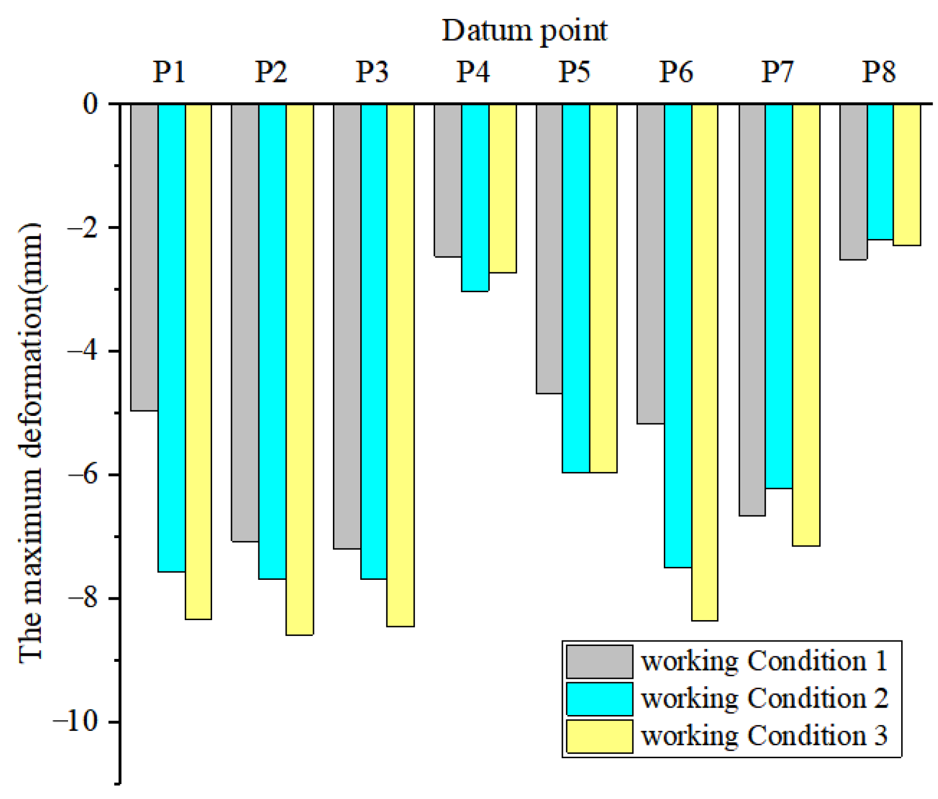
4.3. Comparison of Partitioned Excavation Methods

From the above analysis, it can be seen that:
(1) In the step-by-step excavation of the foundation pit, the deformation of the ground surface around the foundation pit under different working conditions is characterized by lateral displacement and uplift of the soil at the bottom of the foundation pit. The surface settlement of symmetrical excavation under working Conditions 1 and 2 is small. The final deformation of the shared retaining pile tilts toward the excavation district. When the soil on both sides of the pile shaft is unloaded, the deformation of the retaining pile is “linear shaped”;
(2) When the foundation pit is adopted synchronous partitioned excavation, the deformation of the ground surface around the foundation pit, the deformation of the exterior retaining pile, and in the pit-in-pit district under various working conditions are consistent with the deformation of step-by-step excavation. The deformation difference of the shared retaining pile is obvious. The deformation of the shared retaining pile is small, and the deformation is consistent when the same layer is excavated synchronously. The deformation of the pile shaft is complex, uneven distribution of internal forces that are prone to mutation under the layered synchronous excavation;
(3) When the foundation pit is excavated step-by-step, the symmetrical excavation method should be preferred, and the smaller district should be excavated first; the construction method of synchronous excavation in the same layer is more beneficial to control the overall deformation of the foundation pit under the fully considering the engineering economy and the feasibility of construction organization.
In summary, the LDCFP engineering based on the paper adopts the construction method of step-by-step partitioned excavation using Condition 1.

5. Foundation Pit Monitoring Design

In order to ensure the stability of the foundation pit during construction, according to the characteristics of step-by-step partitioned excavation in different districts of the LDCFP engineering, in-site monitoring of deformation during construction was carried out. The surface deformation around the foundation pit and retaining structure was analyzed.

5.1. Monitoring Plan Design

Based on the LDCFP engineering, the lateral displacement of the retaining pile, the surface deformation around the foundation pit, and the supporting axial force were monitored. The locations of the measuring points are shown in Figure 21.
(1) Install the inclinometer tube in the retaining structure. The inclinometer tube depth is the same as the length of the retaining structure and is laid every 25–30 m along the longitudinal direction of the foundation pit, named CX1–CX61. The settlement measuring points are laid into section form along with the foundation pit, and the spacing is 25 m;
(2) The support system of this engineering is complex, in which six supports are set along the depth direction of the foundation pit in the central district, and 35 axial force monitoring points are set for each support layer in the bowknot district. Two reinforced concrete support and one steel support are used in the pit-in-pit district, and 30 axial force monitoring points are set in each layer. Two supports are set along the depth direction of the foundation pit in the northern and southern districts, and 17 axial force monitoring points are set in each layer.

5.2. Control Standard of Foundation Pit Deformation

Due to the large excavation volume, complicated excavation steps, and complex surrounding environment, the LDCFP engineering is determined to be a primary underground space foundation pit after engineering risk assessment. According to the relevant provisions on the design and monitoring value of foundation pit deformation and the maximum horizontal displacement allowable value of the support structure in the current Chinese specification [37], the importance level is determined as the first level of the deformation control value, as shown in Table 3.

5.3. Deformation Monitoring Results

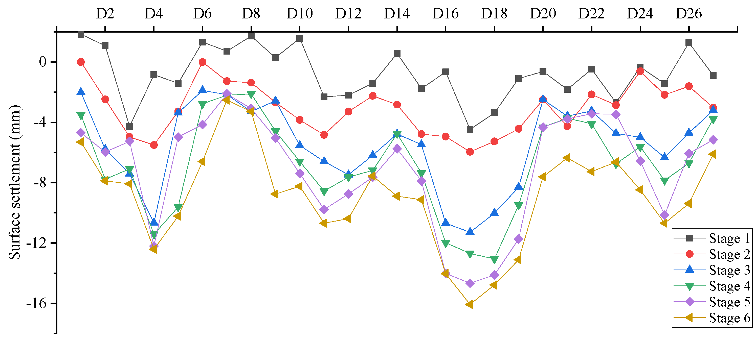
5.3.1. Surface Settlement Outside the Foundation Pit

In this LDCFP engineering, a total of 27 surface subsidence monitoring points were laid. The surface deformation around the foundation pit is shown in Figure 22. Among them, the upward displacement (uplift) is positive, and the downward displacement (settlement) is negative.
From Figure 22, the following can be seen:
(1) Most of the surface deformation values of each monitoring point are negative, and there is surface uplift at some monitoring points because the pile shaft is floating at the stage of the construction of the retaining pile and the column pile, resulting in individual surface soil uplift, and the uplift is within 5 mm;
(2) In the process of foundation pit excavation, the surface deformation caused by the first and second steps of excavation is small, while the surface deformation significantly after the completion of the third step of excavation, and the deformation of the northern side of the bowknot is close to the final deformation. Because the pit-in-pit district is far from the northern side of the foundation pit, the excavation of the pit-in-pit has little effect on the northern supporting structure;
(3) There are two valley values in the surface deformation curve after the completion of foundation pit excavation. The maximum deformation of measuring point D17 can reach −16.35 mm. It was observed that the two monitoring points are located near the midpoint of the “linear pit edge” of the foundation pit. The deformation of measuring points D8-D14 and D23-D27 located at the “arc pit edge” of the foundation pit has little difference in each excavation stage, and the deformation is generally small. This shows that the deformation around the foundation pit in the central district is affected by the geometric shape of the foundation pit; that is, the deformation at the midpoint of the “straight pit edge” is the maximum, and the maximum decreases gradually as the pit angle increases, while the deformation of around the “arc pit edge” is relatively uniform.

5.3.2. Deep Displacement of the Retaining Structure

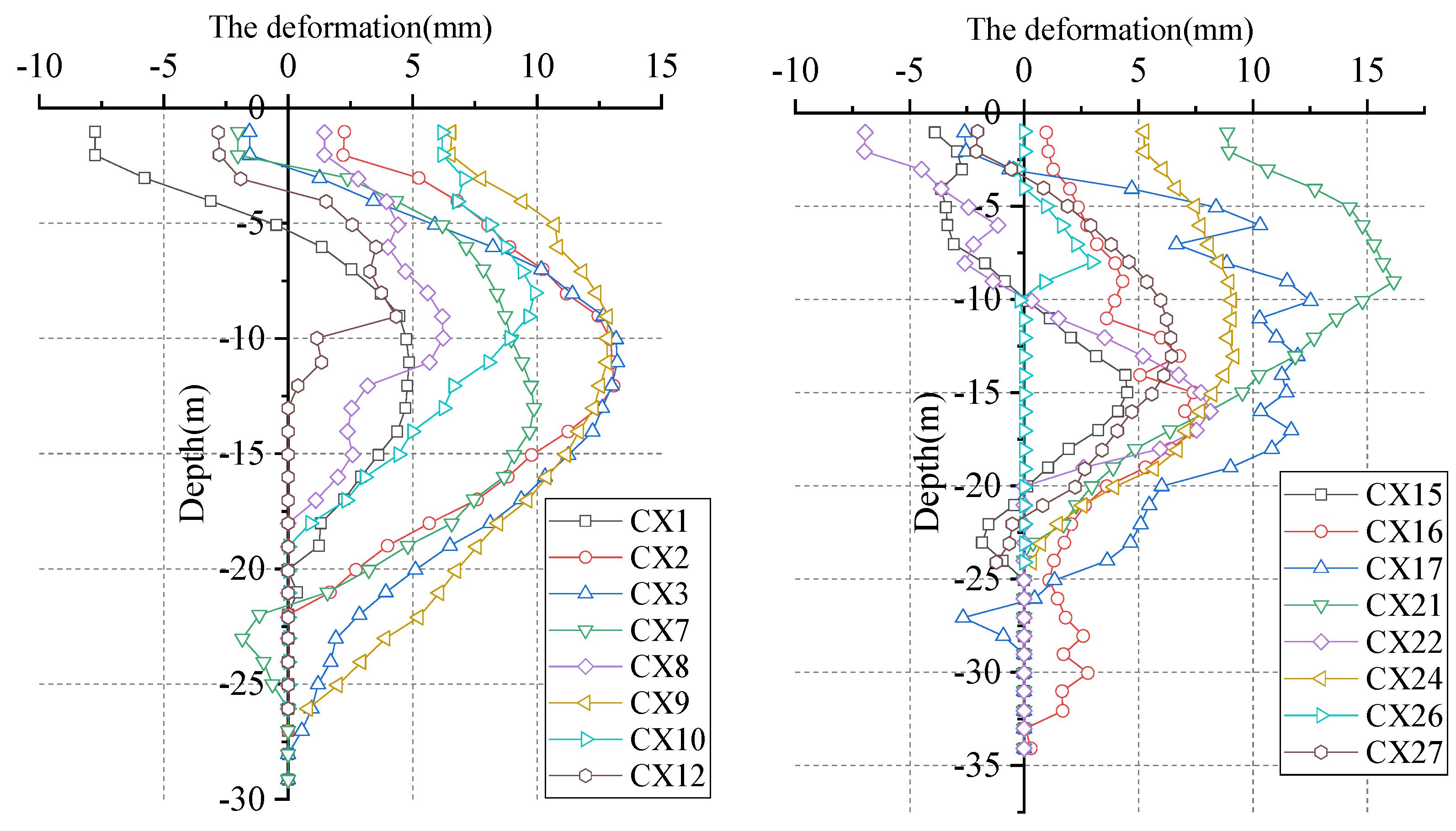
Deep Displacement of Bowknot District Excavation

When excavating to the bottom of the bowknot district (the third layer of excavation is completed), the deep displacement of the measuring points (CX1–CX27) in the central district of the foundation pit is shown in Figure 23. The displacement of the retaining pile toward the foundation pit is positive, and the displacement to the pit is negative.
The monitoring data in Figure 23 show the following:
(1) Because the first layer of the foundation pit adopts slope excavation, the slope range is large, and the district is complex; thus, some retaining piles have different degrees of negative direction (the displacement around the foundation pit) within the excavation range of the first layer (0–9 m depth);
(2) From the depth of the maximum lateral displacement position, the maximum displacement position of the retaining pile is mainly concentrated in the depth range of 10–15 m of the foundation pit. The foundation pit gradually enters the rock layer from below 16 m, and the tangential displacement of the retaining structure is significantly weakened. This shows that the vertical space effect exists in the circular foundation pit. When the bottom of the foundation pit is a hard rock soil layer, the maximum deformation position of the retaining structure appears above the bottom of the foundation pit because the lateral constraint of the rock layer on the retaining structure is significantly increased. When the bottom of the foundation pit is soft soil, the maximum deformation of the retaining structure occurs under the bottom of the foundation pit because the support system is just too small;
(3) From the maximum lateral displacement of the monitoring points, the monitoring values in the central district of the foundation pit edge in groups I and III are significantly greater than those at the pit foundation angle, indicating that the corner support and the foundation pit angle effect increase the corner stiffness, reflecting the spatial effect of the foundation pit. However, the monitoring values of groups II and IV are not significantly different, indicating that the deformation of retaining piles in the peripheral arc section is not significantly different, and the arc section is not affected by the foundation pit space.

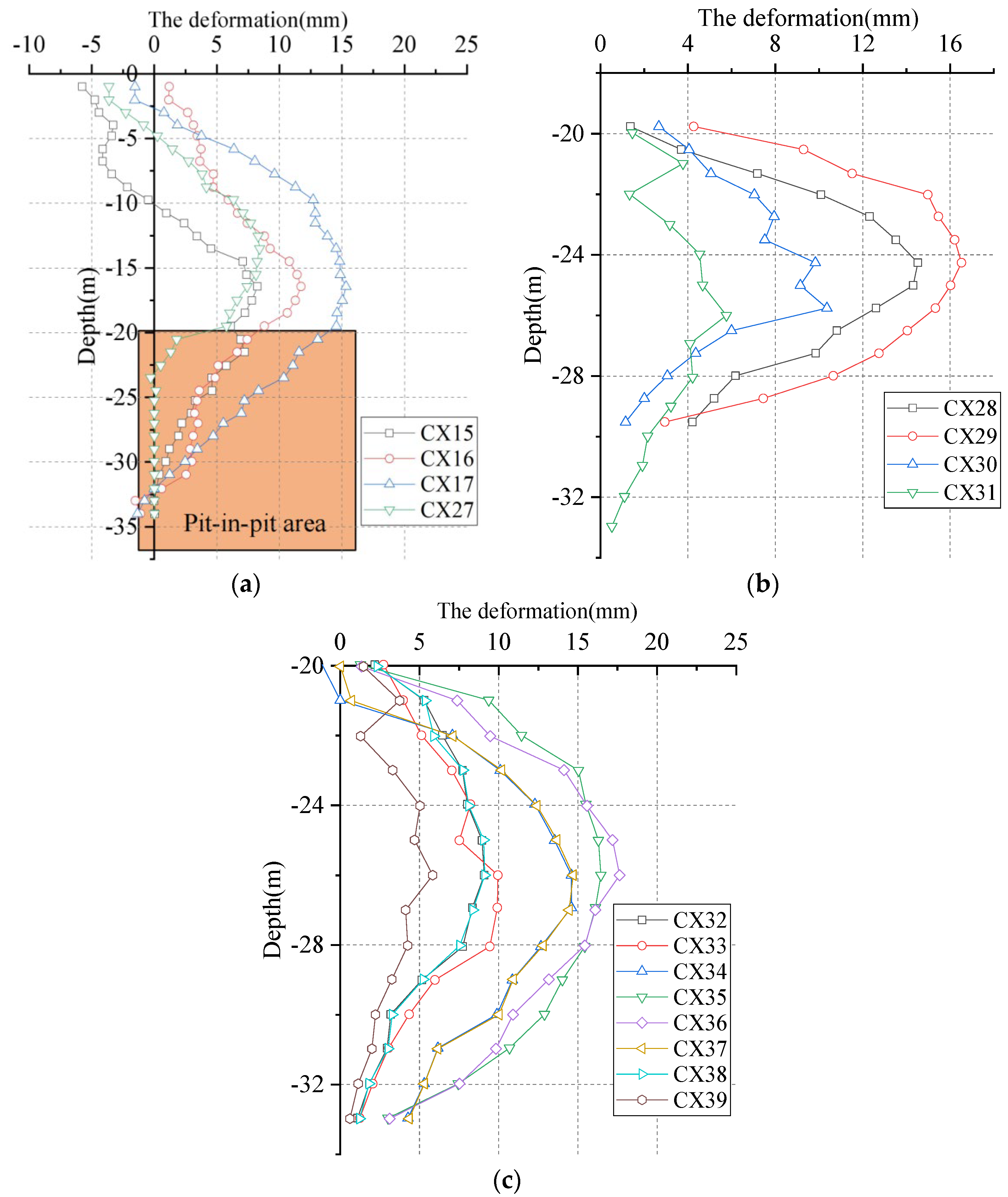
Deep Displacement in the Pit-in-Pit District

After the excavation in the pit-in-pit district is excavated to the bottom (the sixth layer of excavation is completed), the deep displacement of the measuring points on each side of the pit-in-pit district is shown in Figure 24. Among them, CX15, CX16, CX17, and CX27 are the original monitoring points for the construction of the bowknot district, and CX28–CX39 is the new deep displacement of the measuring points for the construction of the pit-in-pit district.
The monitoring data in Figure 24 show the following:
(1) With the downward excavation of the foundation pit, the maximum displacement of CX15, CX16, CX17, and CX27 are increased, and the position of the maximum depth is also gradually moved downward with the excavation and finally stabilized between 15 mm and 20 mm below the foundation pit, which is still above the bottom of the foundation pit;
(2) There is still a spatial effect in the pit-in-pit district; that is, the deformation of the retaining pile near the foundation pit angle is smaller than that near the center of the foundation pit, and the soil at the foundation pit angle and the diagonal part of the angle has a constraint effect;
(3) The deformation of the CX32-CX39 is a “waist drum shaped”, and the maximum lateral displacement of the retaining pile is concentrated in the middle, up to more than 15 mm, and the lateral displacement at the corner is relatively small;
(4) CX15-CX17 and CX28-CX31 are located on the same foundation pit slope at the depths of 20–33 m (the fourth, the fifth, and the sixth layers of the excavation stage), but the deformation is obviously different, mainly reflected in the following two aspects: the deformation of the retaining pile at the CX28-CX31 measuring point is a “waist drum shaped”; that is, the maximum deformation is mainly distributed in the middle of the retaining pile. The deformation of the retaining pile below 20 m at the CX15–CX17 measuring point is “parabolic shaped”, that is, the deformation decreases with the increasing excavation depth. The deformation of CX15–CX17 and CX28–CX31 measuring points at the same burial depth is quite different, which are generally not more than 10 mm for the former and nearly 20 mm for the latter. This is because the upper part of the retaining pile at the CX15–CX17 measuring point is simultaneously supported by the first, second, and third layers of the foundation pit, which plays a constraint role in the deformation of the lower part of the retaining pile.

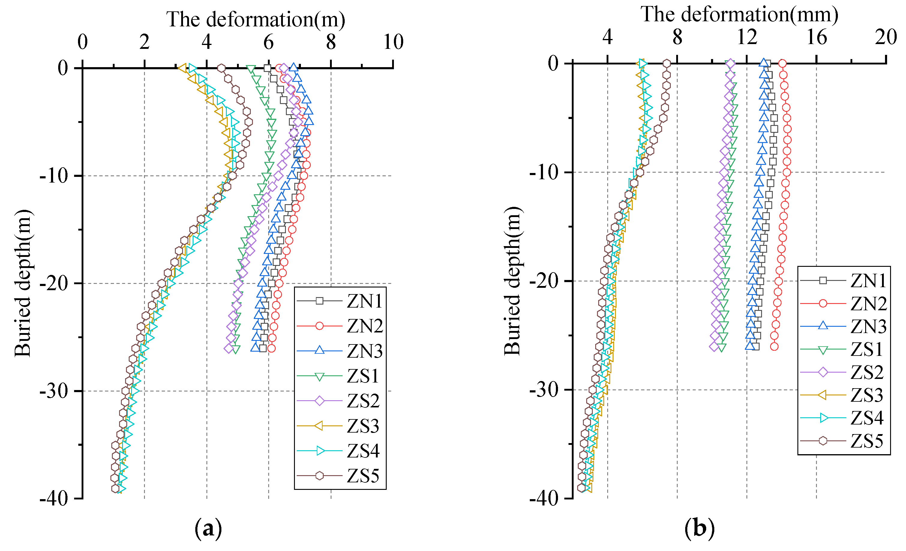
The Deep Deformation in the Northern and Southern Districts

When the excavation in the northern and southern districts is completed, the deep deformation of the measuring points in the central district (CX40–CX61) is shown in Figure 25.
Figure 25 shows that the deformation of the retaining piles in the northern and southern districts is relatively consistent, showing a “waist drum shaped”. The retaining pile is weakly affected by the spatial effect of the foundation pit. The deformation of the retaining structure in the northern–southern districts is significantly smaller than that in the central district, which reflects the uniform stress characteristics of the circular retaining structure. The stress characteristics of the circular retaining structure are conducive to the control of the overall deformation of the foundation pit.

5.3.3. Support Axial Force Monitoring

By taking the central district as an example, the axial force variation curve of each layer support in each construction stage was analyzed, as shown in Figure 26.
The axial force of the internal support of the foundation pit is shown as the second, third and fourth internal supports when excavating to the bottom of the foundation pit.
The axial force is significantly greater than that of the first support, and the axial forces of the second and third supports are relatively close. The axial force of the fourth support is the largest. The axial force of the reinforced concrete support in each channel generally increases with the increasing excavation depth, and the growth rate gradually slows with the excavation. After the excavation of the first soil layer, the axial force of the first support basically remained stable at approximately 1500 kN; the axial force of the second support obviously changed during the excavation of the second and third layers, and the axial force tended to be stable during the excavation. The axial force of the third support increases slowly with the excavation; the axial force of the fourth concrete support is much larger than that of the fifth and sixth steel supports, which is related to the formation conditions of the two supports.
Figure 26. The axial force of the support in the central district.
Buildings 12 01292 g026
In summary, the deformation of the surrounding soil and retaining structure does not appear as an early warning in the whole monitoring period, which reflects the construction safety of retaining piles in LDCFP. It is indicated that a reasonable support method is the premise of the foundation pit safety.

5.3.4. Comparison of Monitoring Results and Numerical Simulation

In order to verify the reliability of the foundation pit excavation design, numerical simulation and monitoring results were compared. After the foundation pit excavation was completed, the comparison between surface deformation monitoring and numerical simulation calculation at each monitoring point of the foundation pit is shown in Figure 27. Only part of the retaining piles after the foundation pit excavation were selected for comparative analysis of the deformation of the retaining structure, and the measuring points CX10, CX14, CX24, and CX40 were selected as the research objects. After the foundation pit excavation was completed, the comparison between the monitoring and numerical simulation of the deformation of the retaining piles is shown in Figure 28.
It can be seen from Figure 27 and Figure 28 that the monitoring results and the numerical simulation results have the same deformation trend, but there are certain differences in the numerical value, which is shown by the large fluctuation of the monitoring value and the concentrated change in the numerical simulation results. The reasons are as follows: (a) The deformation of retaining structure involves a wide range of soil, but in the numerical simulation, the scope of calculation and simulation is reduced by conditional assumptions; (b) The physical and mechanical parameters of the soil are affected by various factors such as construction conditions and have randomness. The foundation pit space of the project is large, and the stratum conditions and groundwater conditions are complex; (c) The size of this simulation is too large, and there are many grid elements. The research has simplified the actual soil layer and has a certain impact on the numerical calculation; (d) It is difficult to accurately calculate the disturbance degree load of undisturbed soil caused by construction.
Figure 27. Comparison of surface settlement.
Buildings 12 01292 g027
Figure 28. Comparison of the deformation for the retaining structure.
Buildings 12 01292 g028

6. Conclusions and Discussion

Based on the LDCFP engineering of a subway station in Wuhan, China, the paper analyzes the characteristics of various partitioned excavation methods. step-by-step and synchronous excavation. The surface deformation around the LDCFP and the deformation of the retaining structure are analyzed by numerical simulation and field monitoring, and the excavation deformation characteristics of the circular foundation pit are revealed. The main conclusions are as follows:
(1) When the LDCFP is excavated step by step, the symmetrical excavation method should be preferred, and the smaller district should be excavated first; in the synchronous excavation of the foundation pit partition, under the premise of fully considering the engineering economy and the feasibility of construction organization, the construction method of synchronous excavation of the same layer is more conducive to controlling the overall deformation of the foundation pit;
(2) Under different excavation processes, the deformation characterized by lateral displacement around the foundation pit, surface deformation, soil uplift at the bottom, the deformation of the retaining piles in the periphery, and the pit-in-pit district is consistent. The deformation difference caused by the process is mainly reflected in the deformation of the shared retaining pile, and the final deformation of the pile is tilted toward the excavation district of the foundation pit. When both sides of the pile are unloaded, the deformation of the retaining pile rebounds in a linear shape;
(3) During the excavation of the foundation pit, the axial force of the support in each layer gradually increases with the excavation. The axial force of the support increases rapidly in the early stage and slows down in the late stage. Under the same constraint conditions, the axial force of the bottom support is greater than that of the upper support;
(4) Through the analysis of monitoring data and numerical simulation results, it was found that the deformation of the circular retaining structure is small and relatively uniform, indicating that the “vault effect” of the circular structure has a certain constraint on the deformation of the foundation pit and the retaining structure;
(5) The circular foundation pit has special spatial stress characteristics; it can give full play to the characteristics of strong compressive capacity under the action of axial load. It has the advantages of large stiffness, small wall deformation, and convenient mechanized operation of LDCFP. As the traffic environment and geological environment around each LDCFP engineering are different, specific analysis is required.

Author Contributions

Conceptualization, H.S., Z.J. and M.B.; methodology, H.S. and Z.C.; software, H.S.; validation, T.W., Z.C. and K.Y.; formal analysis, D.Z. and K.Y.; investigation, Z.C.; data curation, H.S. and T.W.; writing—original draft preparation, H.S. and M.B.; writing—review and editing, Z.J. and T.W.; visualization, D.Z. and Z.C.; supervision, K.Y.; project administration, H.S. and Z.C.; funding acquisition, H.S., T.W. and Z.C. All authors have read and agreed to the published version of the manuscript.

Funding

This research was funded by the Fundamental Research Funds for the Central Universities (No.2021RC208), the National Key Research and Development Program of China (No. 2018YFC0808701), the Shanghai Science and Technology Committee (No. 20DZ1202100, 20DZ2251900), the Tianjin Transportation Technology Development Plan Project (No. 2019B-25), and the central government guides local science and technology development fund projects (No. 216Z3802G).

Institutional Review Board Statement

Not applicable.

Informed Consent Statement

Not applicable.

Conflicts of Interest

We declared that we have no conflict of interest in this work. We declare that we do not have any commercial or associative interest that represents a conflict of interest in connection with the work submitted.

References

  1. Boone, S.J. Analysis of wall and ground movements due to deep excavations in soft soil based on a new worldwide database. Soils Found. 2005, 45, 165–166. [Google Scholar] [CrossRef]
  2. Greeman, A. Station stops. Tunn. Tunn. Int. 2012, 7, 52–56. [Google Scholar]
  3. Zhou, N.; Vermeer, P.A.; Lou, R.; Tang, Y.; Jiang, S. Numerical simulation of deep foundation pit dewatering and optimization of controlling land subsidence. Eng. Geol. 2010, 114, 251–260. [Google Scholar] [CrossRef]
  4. Hsieh, H.S.; Huang, Y.H.; Hsu, W.T.; Ge, L. On the system stiffness of deep excavation in soft clay. J. GeoEngineering 2017, 12, 21–34. [Google Scholar]
  5. Tan, Y.; Wang, D.L. Characteristics of a large-scale deep foundation pit excavated by the central-island technique in Shanghai soft clay. II: Top-down construction of the peripheral rectangular pit. J. Geotech. Geoenviron. Eng. 2013, 139, 1894–1910. [Google Scholar] [CrossRef]
  6. Sharma, J.s.; Hefny, A.M.; Zhao, J.; Chan, C. Effect of large excavation on deformation of adjacent MRT tunnels. Tunn. Undergr. Space Technol. 2001, 16, 93–98. [Google Scholar] [CrossRef]
  7. Zhou, F.; Zhou, P.; Li, J.; Lin, J.; Ge, T.; Deng, S.; Ren, R.; Wang, Z. Deformation characteristics and failure evolution process of the existing metro station under unilateral deep excavation. Eng. Fail. Anal. 2021, 131, 105870. [Google Scholar] [CrossRef]
  8. Finno, R.J.; Blackburn, J.T.; Roboski, J.F. Three-dimensional effects for supported excavations in clay. J. Geotech. Geoenviron. Eng. 2007, 133, 30–36. [Google Scholar] [CrossRef] [Green Version]
  9. Ding, Z.; Jin, J.; Han, T.C. Analysis of the zoning excavation monitoring data of a narrow and deep foundation pit in a soft soil area. J. Geophys. Eng. 2018, 15, 1231–1241. [Google Scholar] [CrossRef] [Green Version]
  10. Chen, R.; Meng, F.; Li, Z.; Ye, Y.; Ye, J. Investigation of response of metro tunnels due to adjacent large excavation and protective measures in soft soils. Tunn. Undergr. Space Technol. 2016, 58, 224–235. [Google Scholar] [CrossRef] [Green Version]
  11. Houhou, M.N.; Emeriault, F.; Belounar, A. Three-dimensional numerical back-analysis of a monitored deep excavation retained by strutted diaphragm walls. Tunn. Undergr. Space Technol. 2018, 83, 153–164. [Google Scholar] [CrossRef]
  12. Teparaksa, W.; Teparaksa, J. Comparison of diaphragm wall movement prediction and field performance for different construction techniques. Undergr. Space 2019, 4, 225–234. [Google Scholar] [CrossRef]
  13. Ranjan, H.S.; Rao, S. Analysis of the effect of anchor rod on the behavior of diaphragm wall using plaxis 3d. Aquat. Procedia 2015, 4, 240–247. [Google Scholar]
  14. Cui, X.Y.; Ye, M.G.; Zhuang, Y. Performance of foundation pit supported by bored piles and steel struts: A case study. Soils Found. 2018, 58, 1016–1027. [Google Scholar] [CrossRef]
  15. Lim, A.; Ou, C.Y. Stress paths in deep excavations under undrained conditions and its influence on deformation analysis. Tunn. Undergr. Space Technol. 2017, 63, 118–132. [Google Scholar] [CrossRef]
  16. Wu, J.; Peng, L.; Li, J.; Zhou, X.; Zhong, J.; Wang, C.; Sun, J. Rapid safety monitoring and analysis of foundation pit construction using unmanned aerial vehicle images. Autom. Constr. 2021, 128, 103706. [Google Scholar] [CrossRef]
  17. Tan, Y.; Lu, Y. Responses of shallowly buried pipelines to adjacent deep excavations in Shanghai soft ground. J. Pipeline Syst. Eng. Pract. 2018, 9, 05018002. [Google Scholar] [CrossRef]
  18. Jamsawang, P.; Voottipruex, P.; Tanseng, P.; Jongpradist, P.; Bergado, D.T. Effectiveness of deep cement mixing walls with top-down construction for deep excavations in soft clay: Case study and 3D simulation. Acta Geotech. 2018, 14, 225–246. [Google Scholar] [CrossRef]
  19. Rouainia, M.; Elia, G.; Panayides, S.; Scott, P. Nonlinear finite-element prediction of the performance of a deep excavation in Boston Blue Clay. J. Geotech. Geoenviron. Eng. 2017, 143, 1–45. [Google Scholar] [CrossRef] [Green Version]
  20. Wang, J.; Huang, T.; Hu, J.; Wu, L.; Li, G.; Yang, P. Field experiments and numerical simulations of whirlpool foundation pit dewatering. Environ. Earth Sci. 2014, 71, 3245–3257. [Google Scholar] [CrossRef]
  21. Sun, H.; Chen, Y.; Zhang, J.; Kuang, T. Analytical investigation of tunnel deformation caused by circular foundation pit excavation. Comput. Geotech. 2019, 106, 193–198. [Google Scholar] [CrossRef]
  22. Zhang, G.; Liu, Q.C.; Deng, X. Field measurement and analysis of effect of excavation on existing tunnel boxes of underlying metro tunnel in operating. Rock Soil Mech. 2012, 33, 1109–1116. [Google Scholar]
  23. Liu, T.J. Study on shield tunnel deformation due to foundation pit construction. Chin. J. Rock Mech. Eng. 2008, 27 (Suppl. S2), 3393–4000. [Google Scholar]
  24. Zheng, G.; Wei, S.W. Numerical analyses of influence of overlying pit excavation on existing tunnels. J. Cent. South Univ. Technol. 2008, 15 (Suppl. S2), 69–75. [Google Scholar] [CrossRef]
  25. Huang, X.; Schweiger, H.F.; Huang, H.W. Influence of deep excavations on nearby existing tunnels. Int. J. Geomech 2013, 13, 170–180. [Google Scholar] [CrossRef]
  26. Shi, J.W.; Ng, C.W.; Chen, Y. A simplified method to estimate three-dimensional tunnel responses to basement excavation. Tunn. Undergr. Space Technol. 2017, 62, 53–63. [Google Scholar] [CrossRef]
  27. Zhang, Z.G.; Huang, M.S.; Wang, W.D. Evaluation of deformation response for adjacent tunnels due to soil unloading in excavation engineering. Tunn. Undergr. Space Technol. 2013, 38, 244–253. [Google Scholar] [CrossRef]
  28. Tobar, T.; Meguid, M.A. Comparative evaluation of methods to determine the earth pressure distribution on cylindrical shafts: A review. Tunn. Undergr. Space Technol. 2010, 25, 188–197. [Google Scholar] [CrossRef]
  29. Cheng, Y.M.; Au, S.K.; Hu, Y.Y.; Wei, W.B. Active pressure for circular cut with Berezantzev’s and Prater’s theories, numerical modeling and field measurements. Soils Found. 2008, 48, 621–631. [Google Scholar] [CrossRef] [Green Version]
  30. Suraparb, K.; Boonchai, U. Undrained basal stability of braced circular excavations in non-homogeneous clays with linear increase of strength with depth. Comput. Geotech. 2019, 115, 103180. [Google Scholar]
  31. Cheng, Y.M.; Hu, Y.Y.; Wei, W.B. General axisymmetric active earth pressure by method of characteristics-theory and numerical formulation. Int. J. Geomech. 2015, 7, 1–15. [Google Scholar] [CrossRef]
  32. Meguid, M.A.; Tran, V.D.; Chouinard, L.E. Discrete element and experimental investigations of the earth pressure distribution on cylindrical shafts. Int. J. Geomech. 2014, 14, 80–91. [Google Scholar]
  33. Ng CW, W.; Sun, H.S.; Lei, G.H.; Shi, J.W.; Mašín, D. Ability of three different soil con-stitutive models to predict a tunne’s response to basement excavation. Can. Geotech. J. 2015, 52, 1685–1698. [Google Scholar]
  34. Zhang, X.; Yang, J.; Zhang, Y.; Gao, Y. Cause investigation of damages in existing building adjacent to foundation pit in construction. Eng. Fail. Anal. 2018, 83, 117–124. [Google Scholar] [CrossRef]
  35. Guo, P.; Gong, X.; Wang, Y. Displacement and force analyses of braced structure of deep excavation considering unsymmetrical surcharge effect. Comput. Geotech. 2019, 113, 103102. [Google Scholar] [CrossRef]
  36. Doležalová, M. Tunnel complex unloaded by a deep excavation. Comput. Geotech. 2001, 28, 469–493. [Google Scholar] [CrossRef]
  37. GB/T50123-2019; Standard for Geotechnical Testing Method. Standard of the People’s Republic of China: Beijing, China, 2019.
Figure 1. Excavation site of LDCFP construction.
Buildings 12 01292 g001
Figure 2. The surrounding environment of foundation pit engineering.
Buildings 12 01292 g002
Figure 3. Schematic diagram of the retaining piles.
Buildings 12 01292 g003
Figure 4. Supports design in the central district.
Buildings 12 01292 g004
Figure 5. Supports design in the northern and southern districts.
Buildings 12 01292 g005
Figure 8. The analysis steps of step-by-step partitioned excavation method.
Buildings 12 01292 g008
Figure 9. The surface deformation of the ground surface around the foundation pit.
Buildings 12 01292 g009
Figure 10. The maximum deformation of three working conditions.
Buildings 12 01292 g010
Figure 11. The deformation nephogram of the supporting structure. (a) working Condition 1. (b) working Condition 2. (c) working Condition 3.
Buildings 12 01292 g011
Figure 12. Deformation of the exterior retaining structure. (a) working Condition 1. (b) working Condition 2. (c) working Condition 3.
Buildings 12 01292 g012
Figure 13. Retaining structure deformation in pit-in-pit district. (a) working Condition 1. (b) working Condition 2. (c) working Condition 3.
Buildings 12 01292 g013
Figure 15. Simulation calculation of conditions.
Buildings 12 01292 g015
Figure 16. The deformation characteristics of the ground surface. (a) working Condition 4. (b) working Condition 5.
Buildings 12 01292 g016
Figure 17. Deformation of the exterior retaining structure. (a) working Condition 4. (b) working Condition 5.
Buildings 12 01292 g017
Figure 18. Deformation of retaining structure in pit-in-pit district. (a) working Condition 4. (b) working Condition 5.
Buildings 12 01292 g018
Figure 19. Deformation of the shared retaining structure under working Condition 4. (a) excavate to the bottom of the first layer. (b) excavate to the bottom of the second layer. (c) excavate to the bottom of the foundation pit.
Buildings 12 01292 g019aBuildings 12 01292 g019b
Figure 21. The location of measuring points.
Buildings 12 01292 g021
Figure 22. Surface deformation of excavation in the central district.
Buildings 12 01292 g022
Figure 23. Deep displacement of the retaining structure during bowknot district excavation.
Buildings 12 01292 g023
Figure 24. Deep displacement of the retaining structure during pit-in-pit district excavation. (a) deep displacement (CX15, CX16, CX17 and CX27). (b) deep displacement (CX28, CX29, CX30 and CX31). (c) deep displacement (CX32, CX33, … and CX39).
Buildings 12 01292 g024
Figure 25. The deep deformation in the central district(CX40–CX61).
Buildings 12 01292 g025
Table 1. The soil layer parameters.
Soil LayerPoisson’s Ratio (v)Unit Weight (γ)Secant Stiffness (E50)Tangent Stiffness (Eoed)Modulus of Elasticity (Eur)Shear StrengthSoil Thickness
Cohesion
(c)
The Angle of Internal Friction (φ)
-kN/m3kN/m2kN/m2kN/m2(kPa)(°)m
Fill soil0.3519.54500540031,5005154.5
Clay0.3619.06075729042,52522104.5
Residual soil0.3319.50945011,34066,15035133
Strongly weathered Mudstone0.322.512,60015,12088,20050204
Moderately Weathered mudstone0.324.382,80099,360579,600802215
Slightly weathered mudstone0.2826.5135,000162,000945,00010027-
Table 2. Material parameters of supporting structure.
Supporting StructureMaterial PropertiesSizeModulus of Elasticity/EPoisson’s Ratio/v
-mmkN/m3
Retaining pilesC35 concreteφ1200@15003.25 × 1070.2
Column pileC35 concreteφ12003.25 × 1070.2
First top beamC35 concrete1200 × 24453.15 × 1070.2
Second and third wai purlingC30 concrete1200 × 12003.00 × 1070.2
Fourth top beamC35 concrete1200 × 10003.15 × 1070.2
Fifth and sixth wai purlingC30 concrete1400 × 14003.00 × 1070.2
Supports of first and fourth layerC40 concrete800 × 10003.25 × 1070.2
Support of second layerC40 concrete1000 × 11003.25 × 1070.2
Support of second layerC40 concrete1100 × 12003.25 × 1070.2
Supports of fifth and sixth layersteelsφ800@16 steel pipe7.85 × 10110.3
Table 3. Deformation control values of LDCFPs.
Monitoring ContentControl Value
Displacement of pile top<30 mm
Surface subsidence0.002H, <30 mm
Retaining structure horizontal displacement0.0015H, <20 mm
Maximum displacement<50 mm
Note: 1 H is the depth of excavation.
Publisher’s Note: MDPI stays neutral with regard to jurisdictional claims in published maps and institutional affiliations.

