Abstract
Among the existing passive energy dampers, I-shaped shear dampers had shown suitable performance in experimental and numerical studies. Although they improve the dissipating energy and ductility of concentrically braced frames (CBFs), they reduce the stiffness and ultimate strength of the system. Three approaches are generally used to overcome the problem, including (a) increasing the thinness of the shear plates, (b) increasing the number of shear plates, and (c) using more dampers in more bays. The mentioned approaches increase construction costs. Accordingly, to overcome this shortcoming, in this paper, an innovative shear damper with a trapezoidal shape is proposed and investigated experimentally and numerically. The results indicated that when using the same material for I-shaped shear dampers and the proposed damper, the proposed damper has greater ultimate strength, elastic stiffness, and dissipating energy capacity. Additionally, the flange plates are more effective in the behavior of the proposed damper than the I-shaped damper. Moreover, required equations were proposed to design the damper.
1. Introduction
Among conventional lateral load-bearing steel systems, such as Moment Resisting Frames (MRFs) and Eccentrically Braced Frames (EBFs), Concentrically Braced Frames (CBFs) have greater lateral elastic stiffness and lateral strength than other ones. Although the CBF has suitable lateral stiffness and strength, it suffers low dissipating energy capability in comparison with the other conventional systems. This weakness is because of the susceptibility of its compressive diagonal members to bucking. Buckling of the compressive diagonal members under cyclic loading degrades the system and reduces the capability of seismic energy dissipation [1,2]. To overcome this problem, ideas have been presented during the last decades, including reducing the slenderness ratio [3], utilizing the optimum configuration of the system [4,5], and strengthening the CBF using dissipating energy devices [6]. Additionally, researchers [7] confirmed that the slip between the slab and the beam interface contributed to the energy dissipated by the system, and the ductility demands decreased on other parts, such as the beam ends and the joints.
Using optimal configurations, as well as reducing the slender ratio of the diagonal member does not eliminate the degradation of the CBF system, although they improve the seismic performance of CBFs. Degradation of the stiffness and strength of the CBF system reduces dissipating energy. Among the presented ideas, utilizing dissipating energy devices is more suitable.
By using these devices in a structure, most of the input seismic energy dissipates in these devices. As a result, the damage is mainly limited to the devices [8]. Additionally, energy-absorbing devices reduce the seismic demand of structures [9]. Although these devices enjoy considerable advantages, especially in enhancing dissipation and the energy capability of the structures generally, they impose some additional costs on structural construction [10].
Comparing the energy dampers shows that passive dampers are cheaper and easier to fabricate than active and semi-active dampers. Among the available varieties of passive energy dampers, metallic dampers are one of the most effective and economical mechanisms for the dissipation of seismic energy input, which is achieved through the inelastic deformation of metallic material.
Numerous passive metallic dampers, as a device indirectly added to brace members, have been developed to improve the behavior of the CBF systems and are classified into two categories.
(a) The first category is dampers attached between the floor beam and CBF, including such steel plate-based dampers as added damping and stiffness (ADAS) [11,12], triangle ADAS (TADAS) [13,14], rhombic [15], X-shaped [16], slit [17,18], pre-bent strips [19] and curved steel dampers [20], and shear dampers [21,22]. These dampers have shown desirable seismic performance, but they need high-quality manufacturing. The main weakness of these dampers is the complexity of construction and fabrication. To overcome this shortcoming and employ their advantages, researchers have proposed shear links. Dampers made as shear links are easier to construct. The most famous links that act as dampers are EBF systems [23,24,25], vertical shear links [26,27], and shear dampers [28,29]. In addition to reducing the stiffness, the mentioned dampers have a suitable seismic performance and are easy to build.
(b) The second category of dampers (directly added to the diagonal member) is more economical than indirectly attached dampers in CBF systems. Among the categorized dampers, the braced ductile shear panel [30], the U-Shaped steel [31], torsional beam [32], f taper tube dampers [33], cushion damper [34], buckling-restrained brace (BRB) [35], semi-BRB [36], assembled bolt-connected buckling-restrained brace (AB-BRB) [37], novel external retrofitting sub-structure and self-centering precast bolt-connected steel-plate reinforced concrete buckling-restrained brace frame (SC-PBSPC BRBF) [38,39], U-shaped damper attached to diagonal brace member [40], X-shear damper [41], and box dampers [42] are generally known as the famous dampers.
Although the reviewed dampers enhance the seismic behavior of CBF systems, their manufacturing and implementation has some drawbacks. Generally, these problems cause constructors to use the mentioned dampers only in special buildings. Furthermore, they have no economic justification for conventional buildings, mainly short to moderate buildings [41,43]. In addition to the optimal seismic performance of structures, ease of implementation and economic considerations are other important issues that should be considered to ensure an efficient system. To overcome this problem, in this paper, an innovative passive metallic damper is introduced, which is easier to fabricate and install than the popular dampers such as ADAS, TADAS, viscous dampers, friction dampers, and BRB, which are presently being used worldwide. It is supposed that the damper prevents the nonlinear behavior of diagonal members. In other words, the damper limited the damage to predicted parts (elements of the damper), and other parts of the structures remained elastic. The behavior of the proposed damper is investigated numerically and parametrically. The main feature of this paper is improving the behavior of the I-shaped damper attached directly to the original CBF system using the same materials used for the dampers. The proposed damper is supposed to increase the ultimate strength and stiffness more than the I-shaped damper, which is investigated experimentally and numerically. Moreover, the required formula to design the proposed damper is presented.
2. The Trapezoidal Damper
2.1. Construction Detailing
Figure 1 illustrates the proposed damper. The damper is directly attached to the diagonal element member of the CBF system. As it is expected that the damper acts as a ductile fuse, it prevents to buckling of the diagonal element member of the CBF system. Moreover, it can be easily replaced after a severe earthquake. The damper can be easily assembled and fabricated.
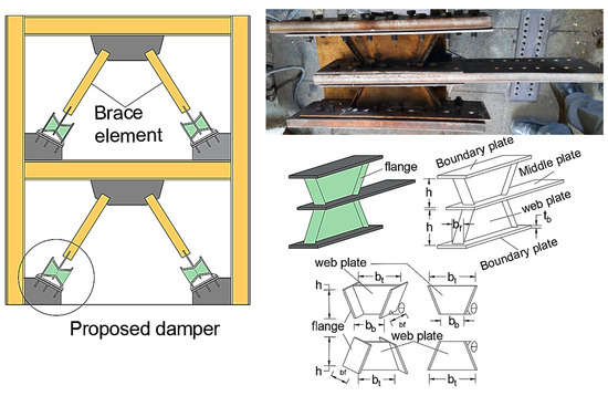
Figure 1.
Construction details of the proposed damper.
The damper is made of a web of trapezoidal-shaped plates that are attached to two flange plates on two sides. Two of the created plates are connected to the middle plates; then, they are surrounded by two boundary plates. It is expected that the middle plates and boundary do not contribute to the load-bearing. Therefore, the imposed load on the damper is resisted by web plates and flanges plates. To create the trapezoidal web plates, plates with two ends angle of can be used. As the angle of principal stress is , therefore, is utilized for the proposed damper. It should be noted that using , an I-shaped link as a damper is shaped. The I-shaped damper has been investigated comprehensively in [43], which is used as a benchmark to compare with the trapezoidal damper.
2.2. The Behavior of the Proposed Damper
As pointed out in the previous section, the middle plate and boundary plates are expected to remain elastic. Accordingly, they do not contribute to resisting the applied loads. Additionally, imposed seismic energy is dissipated by the hinge formation in the web and flange plates. Accordingly, it is expected that the plastic hinges will be formed over the proposed damper, as illustrated in Figure 2. According to the figure, two flexural hinges are formed at the two ends of each flange plate, and a shear hinge is formed in each web plate.
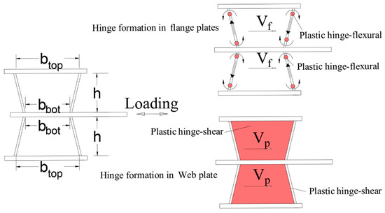
Figure 2.
Formed plastic hinges over the proposed damper.
According to the AISC 341-16 [44], for I-shaped shear links, when the , the shear capacity, , of a shear link is calculated as where is plastic shear capacity. In this equation, the capacity of the flanges plates has been ignored. However, in this paper, the angled flange plates are accounted for in the shear capacity of the trapezoidal damper. Therefore, by accounting web plate and flange plate in determining the shear capacity of the damper, Equation (1) is proposed as:
In this equation, is the shear capacity of the flange plate. As the distributed load is applied to the flange using the web, the capacity of the flange decreases according to = 0.75. So, for this damper, Equation (1) is simplified as .
The behavior of the proposed damper consists of buckling and yielding under applied loading. In the fully shear yielding, the capacity of the proposed damper is reached . The geometry of the proposed damper affected the damper the capacity. The strength of the proposed damper is measured by:
where 2 is the number of main plates and the is the stress on the main plate that is determined based on the buckling and yielding capacity of the main plates.
Based on Basler [45], elastic shear buckling stress, , is obtained from Equation (3). Since the basic materials are steel, by accounting, the Poisson ratio is
Subsequently, the aspect ratio of the damper plate is low, and buckling that occurs in nonlinear zones also should be accounted for.
The stresses in the main plate are established along the angle of . Accordingly, the stresses were as follows.
where, is equivalent yield stress. According to the von Mises yield criterion, the web plate’s yielding occurs when . Since Plan stress is formed in the web plate, the equal to zero. Considering , this equation is simplified as . Substituting Equations (6)–(8) into von Mises yield criterion equations give:
Therefore, the value of at which yielding of the plate occurs is calculated is
The shear capacity stress of the plate is given by Equation (11) for and Equation (12) for .
Additionally, is calculated from Equation (13). This equation has been derived based on the possibility of plastic hinge formation, as illustrated in Figure 2. This equation is simplified of that corresponds to the formation of two flexural plastic hinges at the two ends of the flange plates where is the plastic moment of the flange plate.
where is the yielding stress of the flange plate. Other parameters have been shown in Figure 1.
2.3. Design of the Damper and Elements Outside the Damper
To design the proposed damper, first, Equation (1) is used to design the elements (web and flange plates) of the damper against lateral loading. Substituting Equations (2) and (12) into Equation (1) and simplifying gives:
where V is the imposed axial forces to the diagonal brace element due to lateral loading. Therefore, according to Equation (14), the main and flange plates of the proposed damper are designed. Accordingly, the elements outside the damper are designed according to Equations (15) and (16), according to Figure 3. To assure the elements outside the proposed damper remain elastic, they should be designed for forces greater than the capacity of the damper. To do so, the elements are designed to resist against presented in Equation (15). Accordingly, first, the proposed damper is designed under forces presented in Equation (1), and the elements outside the damper are designed for the amplified capacity, .
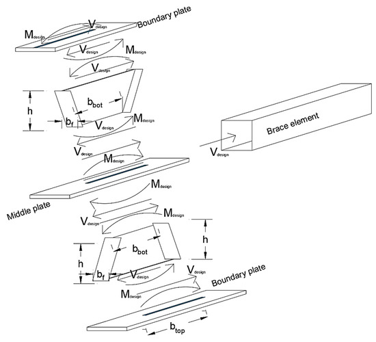
Figure 3.
Free body diagram of the proposed damper.
The proposed approach to design the elements outside the damper follows AISC 341-16, nevertheless the overstrength, (Ω is discussed in the next sections) and , is proposed in this paper. In AISC341-16, a constant value of Ω has been recommended to equal 1.5. Nevertheless, some studies [46,47] showed that Ω is not constant for shear links.
where , is the ratio of expected to nominal yield stress that is measured according to the AISC 341-16. For this damper, it is suggested to . Subsequently, the boundary plates must, against compressive forces, equal and moment of . Additionally, the diagonal element of braces are designed under the axial force of .
In so doing, the ultimate strength of the brace member, , where is nominal resistance in compression should be satisfied, Equation (16). In this equation, and the is the compression force to brace members due to the maxim strength of the damper.
3. Experimental Study
3.1. Preparing the Specimens
Two specimens, an I-shaped damper and a trapezoidal damper, illustrated in Figure 4, were prepared and tested under cyclic loading. To have a fair comparison, the same area section was designed for both dampers. Since the volume of materials used for both dampers is the same, by comparing their behavior, it is possible to evaluate which damper has better performance under completely identical conditions, which will indicate that it is more economical. The thickness of the web and flange plates was selected as 2 mm. Accordingly, the boundary plates and middle plates were designed according to Equation (14), which are plates with a thickness of 25 mm. To examine the capability of the damper’s easy replacement, 6-mm plates were connected to the top and bottom of the main web and flange plates then they were bolted to the middle and boundary plates. The distance between the bolts was designed according to the AISC341-16.
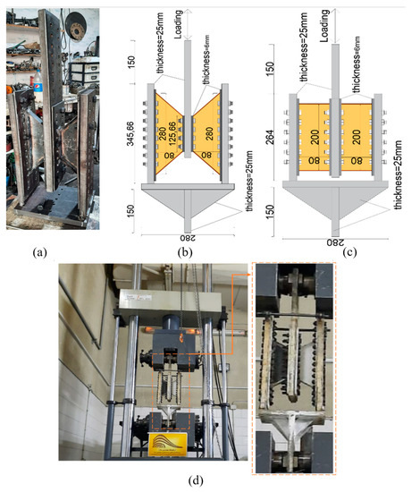
Figure 4.
(a) Prepared Trapezoidal specimen before testing, (b) Trapezoidal specimen detail) I-shaped damper detail, (c,d) Test preparing trapezoidal damper.
For all elements, ST37 steel was used with yielding stress = 235, ultimate strength = 370 MPa, Poisson’s ratio = 0.3, and Young’s modulus = 200 GPa. For bolts, M12 (diameter of 12 mm) and materials of ST59 steel with yielding stress of 590 MPa were used.
3.2. Boundary Condition
The test setup is shown in Figure 4d. The specimens were tested at the International Institute of Earthquake Engineering and Seismology, and the hysteresis curve was automatically captured using the lab equipment. The gusset plate of the damper was fixed at the bottom of the damper, and the actuator applied the defined load cyclically at the top. The loading was measured as displacement control and applied based on AISC-16. Before applying the cyclic loading, a monotonic analysis was performed to determine the yield point displacement (∆y), then it was repeated (three times for each cycle) as ∓∆y, ∓2∆y, etc.
3.3. Experimental Results
3.3.1. Specimen Performance
In Figure 5, the hysteresis curves of the tested specimens are compared. The results of this figure indicate that both dampers have good hysteresis curves with stable performance. As shown in this figure, the trapezoidal damper has better performance in ultimate strength, stiffness, and greater dissipating energy. A small pinching is observed in the hysteresis curves. This pinching is due to hinge formation in the flange and its bucking during the test. These parameters are compared in the next section.
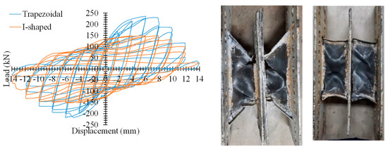
Figure 5.
Experimental test results.
In both the dampers, web and flange plates experience nonlinear behavior, whereas middle plates and boundary plates remain elastic. This behavior confirms the accuracy of Equation (14) in the design of elements outside the damper.
In the trapezoidal specimen, the flange plate buckling and web plate cracking along the tension field occurred at a displacement of 8 mm (rotation = 10% or 0.1 rad). At a displacement of 10 mm (rotation = 12.5% or 0.125 rad), considerable cracking of the web plate appeared, followed by complete cracking at 12 mm (rotation = 15% or 0.15 rad).
For the I-shaped specimen, at the displacement of 8 mm (rotation = 10% or 0.1 rad), the crack propagation was initiated at the location where the web plate was connected to the flange plate. At the displacement of 10 mm (rotation = 12.5% or 0.125 rad), the flange was torn. The damper was resistant up to the displacement of 14 mm (rotation = 17.5% or 0.175 rad); as a result, the web plate tore at the vicinity of the connection to the middle plate. Although in AISC, the ultimate rotation of the shear link is limited to 8% or 0.8 rad, for the proposed damper, no rupturing/cracking occurred for any specimen, even up to a rotation of 10% or 0.1 rad (8 mm). This confirms the ductile behavior of the damper. As none of the bolts was fractured even up to the cracking of the damper, it can be confirmed that the damper can be easily replaced after a severe earthquake
3.3.2. Structural Parameters
The structural parameters of the models are obtained from the ideal bilinear curve, which is obtained from the envelope curves (backbone curve), as shown in Figure 6; the envelope curves are (backbone curve) derived according to FEMA-356. The parameters include elastic stiffness , displacement corresponding to yielding , ductility , force corresponding to the first hinge formation , and that corresponds to the maximum/nominal shear strength of the damper; the structural parameters are listed in Table 1. Additionally, the backbone curve helps to find a better comparison of the results. As the hysteresis curve of the dampers is symmetrical, by extracting the backbone curve, the results of the hysteresis curve can be achieved at high accuracy. The schematic view of the backbone curve of the dampers is plotted in Figure 6.
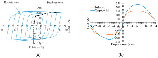
Figure 6.
Skeleton curve of the dampers (a) schematic view (b) extracted for dampers.

Table 1.
Structural parameters of the damper.
Referring to the results, the parameters improved as ultimate strength up to 58%, stiffness around 8%, overstrength 56%, and displacement corresponding to yielding up to 46%, but the ductility is reduced by around 37%. The parametric study is carried out in the next sections to investigate other factors on the structural parameters of the dampers. Additionally, the ultimate strength was calculated by Equation (1) which gave 240.22 kN. It predicted the ultimate strength with +2% and −10% errors.
4. Numerical Study
4.1. Finite Element (FE) Modeling
In this study, the finite element (FE) simulation was carried out using the ANSYS program. For modeling the damper, all elements were simulated utilizing SHELL 181 with six degrees of freedom in each node. This element has the capability to measure large displacement, buckling, and material nonlinearity. Although solid elements (brick elements) could also be used, since the analysis of the models using shell elements takes less time and leads to the same results as solid elements, SHELL 181 was used.
The FE models, as illustrated in Figure 7, were meshed so that each damper is composed of 2328 elements.
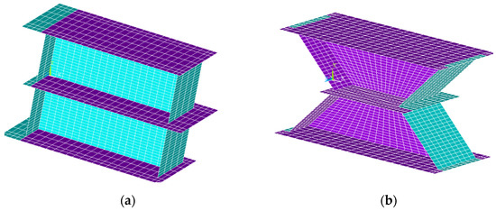
Figure 7.
The view of FE modeling of the dampers to show the mesh sizing (a) I-shaped (b) Trapezoidal.
The boundary condition of the FE models was applied, as shown in Figure 8. Since the end of the damper attached to the gusset plate acts as a rigid connection, its end models as fixed supported. The other end of the damper, where it is connected to the brace member, is simulated as a simple connection, and loading is applied. This determined boundary condition for FE modes is similar to the situation of a real damper without modeling the diagonal element member. The loading was displacement control; it was increased until the amount of drift (rotation) of web plates reached 8% (0.08 radians). Although experimental results have proven that the proposed damper can withstand a rotation of more than 8%, the results of numerical studies suggest that the maximum rotation based on AISC 341-16 is 8%. As indicated in article F3.4a of AISC 341-16, short/shear links attain a maximum rotation of 0.08 rad under seismic loading. Therefore, the maximum displacement of 11.2 mm was applied to the damper to reach the rotation of 0.08 rad.
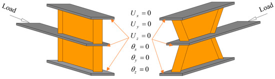
Figure 8.
Boundary conditions for FE simulation.
4.2. Verification of FE Results
In Figure 9, the FE results are compared with experimental test results. As shown in this figure, the FE results are in good agreement with the test results. The FE modeling captures the stiffness of the dampers’ math with the test results in elastic and inelastic zones. However, lower strength using FE is obtained in comparison with the test results.
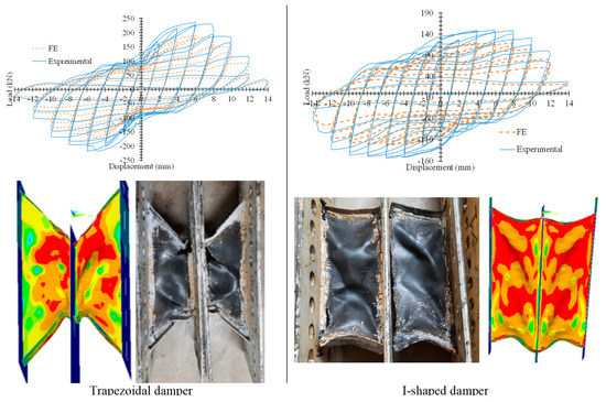
Figure 9.
Tested specimens.
5. Numerical Results
5.1. Hysteresis Curves
Figure 10 illustrates the hysteresis curves of the I-shaped damper and trapezoidal damper. To show the overall cyclic behavior of these dampers, dampers with minimum and maximum tf have been compared. As shown in this figure, either damper pertains to stable hysteresis curves without degradation. Moreover, increasing the tf cause improves the hysteresis curves of the dampers.
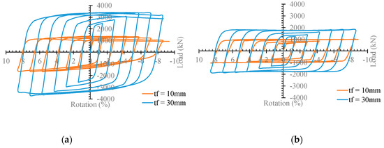
Figure 10.
Comparing the hysteresis curves of the dampers (a) I_shaped (b) Trapezoidal.
To show better performance and since the dampers have a symmetrical hysterics curve, their skeleton curves (backbone curves) are discussed in the next section. To do so, in Figure 11, the load–rotation curves of the damper have been drawn. Referring to the figure provides that by increasing the tf, the load–rotation curves of either damper tend to be enhanced, causing the curves to increase the structural parameters such as elastic stiffness, ultimate strength, and dissipating energy, which is investigated in the next sections. The noticeable problem is that the amplified factor, 1.25 Ry, in the design of the elements outside the damper is less than the ultimate strength. For trapezoidal damper, the has been calculated according to the that is the maxim b for the damper. Therefore, estimating the maxim load to the design of elements outside the damper according to the AISC-360-16 is unconservative. To do so, the overstrength related to the dampers should be used.
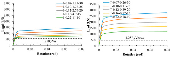
Figure 11.
The load-rotation curves of the dampers.
5.2. Comparing the I-Shaped Damper with the Trapezoidal Damper
In Figure 12, the load rotation of the I-shaped damper with the trapezoidal damper is compared. As shown in this figure, the trapezoidal damper has a better performance than the I-shaped damper in the case of ultimate strength, elastic stiffness, and dissipating energy. According to the comparison in this figure, the load–rotation curve of the trapezoidal damper with tf = 10 mm is close to the I-shaped damper with tf = 25 mm. It is shown that trapezoidal dampers with less material can achieve a closer behavior than the I-shaped damper. The structural parameters are listed in Table 2.
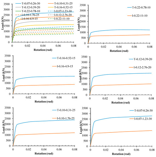
Figure 12.
Comparing the load–rotation curves of the dampers.
Table 2.
Comparing the structural parameters of the dampers.
Results indicated that using a trapezoidal damper instead of an I-shaped damper increased the ultimate strength (Vn) between 61% and 92%, elastic stiffness (K) between 29% and 56%, and the energy dissipating (E) between 1.67 and 2.03 times, forces corresponding to the first yielding (Vs) between 28% and 56% that is similar to the K. Additionally, overstrength (Ω) was enhanced between 23% and 35%, but by increasing the tf, its rate was reduced. Moreover, the ductility (μ) was reduced by around 20%.
In Figure 13, the ratio of the parameters for the trapezoidal damper to the I-shaped damper versus tf is plotted. This figure indicates that the most increasing due to trapezoidal damper divide by I-shaped damper is related to, respectively, E, Vn, K, and Ω. This figure also shows the rate of increasing the parameters versus tf.
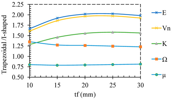
Figure 13.
Ratio of parameters of the trapezoidal damper to I-shaped damper versus tf.
5.3. Stiffness
Comparing the trapezoidal damper with the I-shaped damper indicates that the trapezoidal has greater elastic stiffness than the I-shaped. Additionally, the stiffness in the nonlinear zone is plotted versus rotation in Figure 14. This figure shows that the stiffness of the damper coincides together around a rotation of 0.006 Rad. In the other words, although the types of damper (I-shaped or trapezoidal) and thickness of the flange plate are effective on the stiffness, they do not have a considerable effect on the stiffness after rotation more than 0.006 Rad.
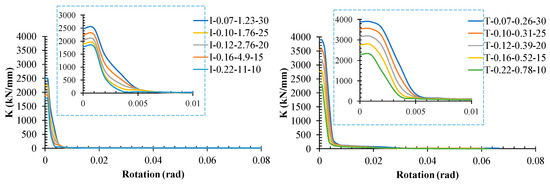
Figure 14.
Stiffness of the dampers versus rotation.
As is expected, the stiffness contains the stiffness of the flange plate and web plate (main plate), the stiffness of the elements is plotted in Figure 15. As shown in this figure, for both dampers, more stiffness is provided by web plates than flange plates, but, by increasing the tf, the effect of the flange plate is enhanced. Additionally, the effect of the flange plate in the trapezoidal damper is greater than the I-shaped damper. For the trapezoidal damper, although the stiffness of the web plate is greater than the flange plate, they coincide together at rotation around 0.002 Rad. It is concluded that after emerging yielding in the shear damper, the stiffness of the web plate is reduced, but the flange plate prevents more reduction.
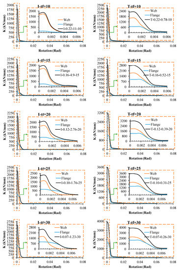
Figure 15.
Stiffness versus rotation in case of web and flange effect.
5.4. Share of Flanges on the Applied Load
According to the AISC-341-16, the flange plate in calculating the shear capacity of shear links is ignored. To consider the effect of the flange plate on the shear capacity of the dampers, the load–rotation for the web and flange plate for the damper is plotted in Figure 16. For a summarized and better showing, the I and T in these figures represent the trapezoidal damper and I-shaped damper, respectively. The tf is given in the Perrantes. According to the figure, the flange plate contributes to load bearing, which confirms the assumption used in this paper to derive the equations govern to the damper’s behavior.
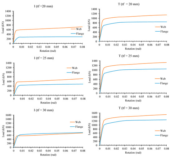
Figure 16.
Load versus rotation for web plate and flange plate.
The I-shaped, thin flange plate has a lower effect in load bearing, and its effect is increased by increasing the tf, whereas in the I-shaped damper with tf = 30 mm, the contribution of the flange plate and web plate is approximately the same. Nevertheless, flange plates in the trapezoidal damper have a greater effect on the contribution of load bearing than I-shaped damper. It is due to the angle of the flange plates. This is the same as the I-shaped damper; the tf causes an increase in the contribution of the flange plate in load bearing. However, even for the high, thick flange plate for the trapezoidal damper, the contribution of the flange plate is lower than the web plate.
To compare the percentage of the share of flange plate and web plate in load bearing, the share of the elements in the capacity of the damper is shown in Figure 17. Referring to the figure, at the beginning of applied loading, most of the loads are resisted by the web plate. Due to hinge formation in the web plate around the rotation of 0.006 Rad, its share in the capacity of the dampers is reduced. Consequently, the share of web plates tended to reduce, and the share of flange plates tended to rise.
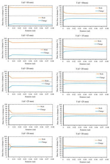
Figure 17.
Share of flange plate and web plate for dampers.
For the I-shaped damper, 92.5% of the capacity of the damper is provided by the web plate at the beginning of the loading when a thin flange is used (7.5% by flange plates). By increasing the rotation, it is reduced to 89% (11% by flange plates). However, this is 70% at the beginning of the applied load and 62% after hinge formation in the web plate for the trapezoidal damper. By increasing the tf from 10 mm to 30 mm, the share of web plate in load bearing at the beginning and after hinge formation in the damper, respectively, changed from 70% and 62% (30% and 38% for flange plates) to 57% and 55% (43% and 45% for flange plates).
5.5. Effect of ρ
According to the AISC-314-16, shear links with ρ < 1.6 gives the shear capacity of Vp. In so doing, the structural parameters versus ρ are plotted in Figure 18 to consider the effect of ρ on the behavior of dampers. Referring to the figure, even though the dampers are designed to be very short links, ρ affects the results even if smaller than 1.6. By increasing the ρ, the structural parameters are reduced. However, the rate of reduction for the trapezoidal damper is greater than for the I-shaped damper. In the other words, the trapezoidal damper is more sensitive than the I-shaped damper. For 0.12 < ρ > 0.25, the effect of ρ on the I-shaped damper dampers is ignorable.
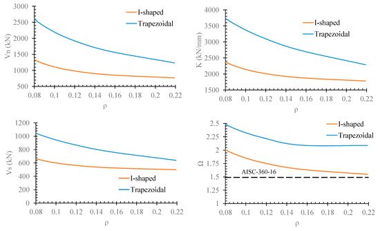
Figure 18.
The effect of ρ on the behavior of dampers.
5.6. Effect of tf
To consider the effect of tf on the behavior of dampers, the structural parameters of dampers with different tf divided by damper with tf =10 mm versus tf are plotted in Figure 19. As shown in this figure, the tf increases (from 10 mm to 30 mm; three times) the Vn, Vs, K, and Ω up to 1.88, 1.4, 1.4, and 1.35 times for the I-shaped damper, respectively. Nevertheless, for the trapezoidal damper, the tf increases the mentioned parameters, respectively, up to 2.25, 1.7, 1.7, and 1.23. Except for the Ω, the effect of tf on the structural parameters of the trapezoidal is greater than the I-shaped damper. It is concluded that the effect of flange plate thickness is not ignorable on the performance of the shear dampers, especially shear dampers with angled flange plates.
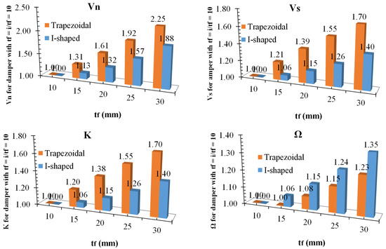
Figure 19.
Structural parameters of dampers versus tf.
Comparing the effect of tf on the parameters Vn, K, and Ω reveals that the tf has the most effect on the Vn for both dampers, Figure 20. However, it has the same effect on K and Ω for the trapezoidal damper. In an I-shaped damper, the effect of tf on the Ω is more than K.
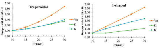
Figure 20.
Comparing the structural parameters of dampers versus tf.
5.7. Effect of ψ
In addition to tf, the non-dimension parameter, ψ, affects the behavior of the damper with different values of θ. As shown in Figure 21, if ψ increases, the strength, stiffness, overstrength, and load corresponding to the first hinge formation decrease. The rate of reduction can be divided into regions with ψ < 1 and ψ > 1. The rate of reduction of the mentioned parameters with ψ < 1 is higher than that in ψ > 1. Therefore, it is suggested to use dampers with ψ < 1. Using ψ < 1, we obtain Vp < Vf. Equation (12) should be satisfied based on the flange thickness.
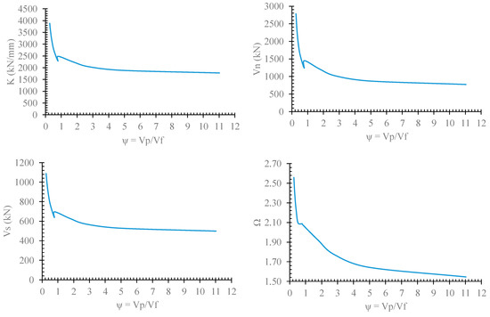
Figure 21.
Nominal strength versus ψ.
5.8. Overstrength
Since the elements outside the dampers are related to the Ω factor, calculating the Ω is important. In so doing, the Ω of the FE models is listed in Table 3. Additionally, the Ω versus tf, ρ, and ψ are plotted in Figure 22 to measure the effect on the parameters on the Ω.
Table 3.
The Ω of the FE models.
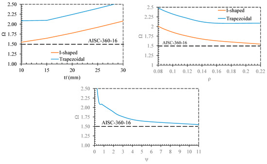
Figure 22.
Considering the Ω.
According to Figure 22, the proposed dampers that were accounted as shear links reveal a Ω more than AISC. In addition to the problem, the Ω is increased by the increase in tf, a reduction in ρ, and a reduction in ψ. Therefore, giving a constant confession for Ω is not logical.
As confirmed, the Ω is affected by all the tf, ρ, and ψ. Since the Ω implicitly includes the conditions of the tf, ρ, therefore, Equation (19), which is derived based on ψ, is suggested to determine the value of Ω. This equation is derived based on the fitting of finite element results. The proposed equation and FE results are compared in Figure 23, which shows a good agreement.
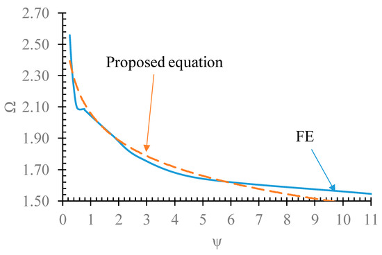
Figure 23.
Comparing the Ω determined by the proposed equation and FE results.
5.9. State of Yielding
Figure 24 illustrates the yielding state of the damper at the rotation of 0.08 Rad. As shown in this figure, the hinge formations in these dampers are in good agreement with the assumption presented in Figure 2. For both dampers, by increasing the flange thickness, the yielding had better distribution over the web plate. Additionally, the middle plate and boundary plates remained elastic. Therefore, it is concluded that the proposed equation presented in the previous section to design elements outside the main elements of the damper is capable. It is expected to remain elastic in the elements outside the web plate and flange plate.
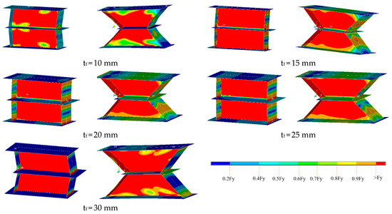
Figure 24.
Yielding state over the dampers.
5.10. Accuracy of the Proposed Damper Equations
In Table 4, the results of proposed relations with FE results are compared. As presented in this table, the proposed equations are in good agreement with FE results.
Table 4.
Comparing the proposed equations with FE results.
6. Conclusions
In this paper, an innovative shear damper with a trapezoidal shape was proposed to improve the behavior of I-shaped dampers and was investigated experimentally and numerically. The proposed damper is easy to fabricate and easy to replace after a severe earthquake. Also, the required equations for the design of the paper were presented. The results are summarized as follows.
- -
- The experimental and numerical study indicated that the trapezoidal dampers have greater ultimate strength, elastic stiffness, dissipating energy, and overstrength than I-shaped.
- -
- Although the flange plate in both dampers affected their behavior, the thicknesses of the flange plate in the trapezoidal damper have more effect on the behavior of the damper than the I-shaped damper.
- -
- The amplified factor, 1.25 Ry, to the design of the elements outside the damper is less than the ultimate strength. Therefore, to design elements outside the damper, using is suggested. In this relation, the overstrength is proposed as .
- -
- Numerical results indicated that when using a trapezoidal damper instead of an I-shaped damper, the ultimate strength is between 61% and 92%, elastic stiffness (K) between 29% and 56%, and the energy dissipating (E) between 1.67 and 2.03 times are improved.
- -
- The stiffness of the damper coincides together around the rotation of 0.006 Rad. In the other words, although the types of damper (I-shaped or trapezoidal) and thickness of the flange plate are effective on the stiffness, they do not have a considerable effect on the stiffness after rotation more than 0.006 Rad.
- -
- For an I-shaped damper, 92.5% of the capacity of the damper is provided by a web plate at the beginning of the loading when a thin flange is used (7.5% by flange plates). By increasing the rotation, it is reduced to 89% (11% by flange plates). However, this is 70% at the beginning of the applied load and 62% after hinge formation in the web plate for the trapezoidal damper.
- -
- By increasing the tf from 10 mm to 30 mm, the share of web plate in load bearing at the beginning and after hinge formation in the damper, respectively, change from 70% and 62% (30% and 38% for flange plates) to 57% and 55% (43% and 45% for flange plates).
- -
- Comparing the effect of tf on the parameters Vn, K, and Ω reveals that the tf has the most effect on the Vn for both dampers. However, it has the same effect on K and Ω for the trapezoidal damper. In an I-shaped damper, the effect of tf on the Ω is more than K.
- -
- Recommendations for future work: To complete the research in this field, it is recommended to investigate the effect of the proposed damper to improve the behavior of reinforced concrete (RC) systems, especially for existing structures. Since the damper improves the behavior of the CBF system, can be built easily, and does not impose much cost on a structure, a comprehensive study is needed to achieve an optimum configuration between the damper and RC frame.
Author Contributions
Conceptualization, A.G.; methodology, A.G.; software, A.G.; validation, C.T. and O.B.; formal analysis, A.G.; investigation, C.T., A.G., R.P.J. and O.B.; resources, R.P.J.; data curation, C.T., R.P.J. and O.B.; writing—original draft preparation, A.G.; writing—review and editing, C.T., A.G., R.P.J. and O.B.; visualization, C.T., R.P.J. and O.B.; project administration, R.P.J.; funding acquisition, R.P.J. All authors have read and agreed to the published version of the manuscript.
Funding
The support provided by Universiti Malaysia Pahang (research grant number PDU213219).
Data Availability Statement
Not applicable.
Conflicts of Interest
The authors declare no conflict of interest.
References
- Ghamari, A.; Jeong, S.H. A proposal for improving the behavior of CBF braces using an innovative flexural mechanism damper, an experimental and numerical study. Steel Compos. Struct. 2022, 45, 455–466. [Google Scholar] [CrossRef]
- Park, H.-Y.; Oh, S.-H. Structural performance of beam system with T-stub type slit damper. Eng. Struct. 2020, 205, 109858. [Google Scholar] [CrossRef]
- Heidari, P.S.; Jazany, R.A.; Kayhani, H. An Investigation on Bracing Configuration Effects on Behavior of Concentrically Braced Steel Frames. World Appl. Sci. J. 2012, 17, 1095–1108. [Google Scholar]
- Yang, T.Y.; Sheikh, H.; Tobber, L. Influence of the Brace Configurations on the Seismic Performance of Steel Concentrically Braced Frames. Front. Built Environ. 2019, 5, 27. [Google Scholar] [CrossRef]
- Jaisee, S.; Yue, F.; Ooi, Y.H. A state-of-the-art review on passive friction dampers and their applications. Eng. Struct. 2021, 235, 112022. [Google Scholar] [CrossRef]
- De Domenico, D.; Ricciardi, G.; Takewaki, I. Design strategies of viscous dampers for seismic protection of building structures: A review. Soil Dyn. Earthq. Eng. 2019, 118, 144–165. [Google Scholar] [CrossRef]
- Vasdravellis, G.; Valente, M.; Castiglioni, C. Dynamic response of composite frames with different shear connection degree. J. Constr. Steel Res. 2009, 65, 2050–2061. [Google Scholar] [CrossRef]
- Symans, M.D.; Charney, F.A.; Whittaker, A.S.; Constantinou, M.C.; Kircher, C.A.; Johnson, M.W.; McNamara, R.J. Energy Dissipation Systems for Seismic Applications: Current Practice and Recent Developments. Eng. Struct. 2008, 134, 3–21. [Google Scholar] [CrossRef]
- Hu, S.; Wang, W.; Qu, B. Seismic evaluation of low-rise steel building frames with self-centering energy-absorbing rigid cores designed using a force-based approach. Eng. Struct. 2020, 204, 110038. [Google Scholar] [CrossRef]
- Ghamari, A.; Almasi, B.; Kim, C.-H.; Jeong, S.-H.; Hong, K.-J. An Innovative Steel Damper with a Flexural and Shear–Flexural Mechanism to Enhance the CBF System Behavior: An Experimental and Numerical Study. Appl. Sci. 2021, 11, 11454. [Google Scholar] [CrossRef]
- Xia, C.; Hanson, R.D. Influence of ADAS Element Parameters on Building Seismic Response. Eng. Struct. 1992, 118, 1903–1918. [Google Scholar] [CrossRef]
- Khazaei, M. Investigation on Dynamics Nonlinear Analysis of Steel Frames with Steel Dampers. Procedia Eng. 2013, 54, 401–412. [Google Scholar] [CrossRef][Green Version]
- Tsai, K.C.; Chen, H.W.; Hong, C.P.; Su, Y.F. Design of steel triangular plate energy absorbers for seis-mic-resistant construction. Earthq. Spectra 1993, 9, 505–528. [Google Scholar] [CrossRef]
- Gray, M.G.; Christopoulos, C.; Packer, J.A. Design and Full-Scale Testing of a Cast Steel Yielding Brace System in a Braced Frame. J. Struct. Eng. 2017, 143, 04016210. [Google Scholar] [CrossRef]
- Han, Q.; Jia, J.; Xu, Z.; Bai, Y.; Song, N. Experimental evaluation of hysteretic behavior of rhombic steel plate dampers. Adv. Mech. Eng. 2014, 9, 99. [Google Scholar] [CrossRef]
- Guo, W.; Wang, X.; Yu, Y.; Chen, X.; Li, S.; Fang, W.; Zeng, C.; Wang, Y.; Bu, D. Experimental study of a steel damper with X-shaped welded pipe halves. J. Constr. Steel Res. 2020, 170, 106087. [Google Scholar] [CrossRef]
- Oh, S.-H.; Kim, Y.-J.; Ryu, H.-S. Seismic performance of steel structures with slit dampers. Eng. Struct. 2009, 31, 1997–2008. [Google Scholar] [CrossRef]
- Lee, J.; Kim, J. Development of box-shaped steel slit dampers for seismic retrofit of building structures. Eng. Struct. 2017, 150, 934–946. [Google Scholar] [CrossRef]
- Wang, Y.-P.; Chien, C.-S.C. A study on using pre-bent steel strips as seismic energy-dissipative devices. Earthq. Eng. Struct. Dyn. 2009, 38, 1009–1026. [Google Scholar] [CrossRef]
- Hsu, H.L.; Halim, H. Improving seismic performance of framed structures with steel curved dampers. Eng. Struct. 2017, 130, 99–111. [Google Scholar] [CrossRef]
- Okazaki, T.; Engelhardt, M.D.; Hong, J.-K.; Uang, C.-M.; Drolias, A. Improved Link-to-Column Connections for Steel Eccentrically Braced Frames. J. Struct. Eng. 2015, 141, 04014201. [Google Scholar] [CrossRef]
- Ghamari, A.; Haeri, H.; Khaloo, A.; Zhu, Z. Improving the hysteretic behavior of Concentrically Braced Frame (CBF) by a proposed shear damper. Steel Compos. Struct. 2019, 30, 383–392. [Google Scholar]
- Roeder, C.W.; Popov, E.P. Inelastic behavior of eccentrically braced steel frames under cyclic load-ings. STIN 1977, 78, 20375. [Google Scholar]
- Roeder, C.W.; Popov, E.P. Eccentrically Braced Steel Frames for Earthquakes. J. Struct. Div. 1978, 104, 391–412. [Google Scholar] [CrossRef]
- Richards, P.W.; Uang, C.-M. Effect of Flange Width-Thickness Ratio on Eccentrically Braced Frames Link Cyclic Rotation Capacity. J. Struct. Eng. 2005, 131, 1546–1552. [Google Scholar] [CrossRef]
- Zahrai, S.M. Cyclic testing of chevron braced steel frames with IPE shear panels. Steel Compos. Struct. 2015, 19, 1167–1184. [Google Scholar] [CrossRef]
- Ghadami, A.; Pourmoosavi, G.; Ghamari, A. Seismic design of elements outside of the short low-yield-point steel shear links. J. Constr. Steel Res. 2021, 178, 106489. [Google Scholar] [CrossRef]
- Deng, K.; Pan, P.; Sun, J.; Liu, J.; Xue, Y. Shape optimization design of steel shear panel dampers. J. Constr. Steel Res. 2014, 99, 187–193. [Google Scholar] [CrossRef]
- Ghamari, A.; Kim, C.; Jeong, S. Development of an innovative metallic damper for concentrically braced frame systems based on experimental and analytical studies. Struct. Des. Tall Spéc. Build. 2022, 31, e1927. [Google Scholar] [CrossRef]
- Giannuzzi, D.; Ballarini, R.; Huckelbridge, A.; Pollino, M.; Valente, M. Braced Ductile Shear Panel: New Seismic-Resistant Framing System. Eng. Struct. 2014, 140, 04013050. [Google Scholar] [CrossRef]
- Taiyari, F.; Mazzolani, F.M.; Bagheri, S. A proposal for energy dissipative braces with U-shaped steel strips. J. Constr. Steel Res. 2019, 154, 110–122. [Google Scholar] [CrossRef]
- Mahyari, S.L.; Riahi, H.T.; Hashemi, M. Investigating the analytical and experimental performance of a pure torsional yielding damper. J. Constr. Steel Res. 2019, 161, 385–399. [Google Scholar] [CrossRef]
- He, Z.; Chen, Q. Upgrading the seismic performance of underground structures by introducing lead-filled steel tube dampers. Tunn. Undergr. Space Technol. 2021, 108, 103727. [Google Scholar] [CrossRef]
- Zkaynak, H. Model proposal for steel cushions for usein reinforced concrete frames. KSCE J. Civ. Eng. 2017, 21, 2717–2727. [Google Scholar] [CrossRef]
- Watanabe, A.; Hitomi, Y.; Saeki, E.; Wada, A.; Fujimoto, M. Properties of brace encased in buck-ling-restraining concrete and steel tube. In Proceedings of the Ninth World Conference on Earthquake Engineering, Tokyo, Japan, 2–9 August 1988; Volume 4, pp. 719–724. [Google Scholar]
- Wang, C.-L.; Qing, Y.; Wu, J.; Wang, J.; Gu, Z. Analytical and experimental studies on buckling-restrained brace with gap-supported tendon protection. J. Constr. Steel Res. 2020, 164, 105807. [Google Scholar] [CrossRef]
- Cao, X.-Y.; Feng, D.-C.; Wang, Z.; Wu, G. Parametric investigation of the assembled bolt-connected buckling-restrained brace and performance evaluation of its application into structural retrofit. J. Build. Eng. 2022, 48, 103988. [Google Scholar] [CrossRef]
- Cao, X.-Y.; Shen, D.; Feng, D.-C.; Wang, C.-L.; Qu, Z.; Wu, G. Seismic retrofitting of existing frame buildings through externally attached sub-structures: State of the art review and future perspectives. J. Build. Eng. 2022, 57, 104904. [Google Scholar] [CrossRef]
- Cao, X.-Y.; Feng, D.-C.; Wu, G.; Wang, Z. Experimental and theoretical investigations of the existing reinforced concrete frames retrofitted with the novel external SC-PBSPC BRBF sub-structures. Eng. Struct. 2022, 256, 113982. [Google Scholar] [CrossRef]
- Qu, B.; Dai, C.; Qiu, J.; Hou, H.; Qiu, C. Testing of seismic dampers with replaceable U-shaped steel plates. Eng. Struct. 2019, 179, 625–639. [Google Scholar] [CrossRef]
- Thongchom, C.; Bahrami, A.; Ghamari, A.; Benjeddou, O. Performance Improvement of Innovative Shear Damper Using Diagonal Stiffeners for Concentrically Braced Frame Systems. Buildings 2022, 12, 1794. [Google Scholar] [CrossRef]
- Miao, F.; Nejati, F.; Zubair, S.A.M.; Yassin, M.E. Seismic Performance of Eccentrical Braced Frame Retrofitted by Box Damper in Vertical Links. Buildings 2022, 12, 1506. [Google Scholar] [CrossRef]
- Ghamari, A.; Kim, Y.-J.; Bae, J. Utilizing an I-shaped shear link as a damper to improve the behaviour of a concentrically braced frame. J. Constr. Steel Res. 2021, 186, 106915. [Google Scholar] [CrossRef]
- AISC. AISC 341-16, Seismic Provisions for Structural Steel Buildings; American Institute of Steel Construction: Chicago, IL, USA, 2016. [Google Scholar]
- Basler, K. Strength of plate girders in shear. J. Struct. Div. 1961, 87, 151–180. [Google Scholar] [CrossRef]
- Hjelmstad, K.D.; Popov, E.P. Seismic Behavior of Active Beam Link in Eccentrically Braced Frames. Rep. No. UCB/EERC-83/15; Earthquake Engineering Research Center, University of California, Berkeley: Berkeley, CA, USA, 1983. [Google Scholar]
- McDaniel, C.C.; Uang, C.-M.; Seible, F. Cyclic Testing of Built-Up Steel Shear Links for the New Bay Bridge. Eng. Struct. 2003, 129, 801–809. [Google Scholar] [CrossRef]


Disclaimer/Publisher’s Note: The statements, opinions and data contained in all publications are solely those of the individual author(s) and contributor(s) and not of MDPI and/or the editor(s). MDPI and/or the editor(s) disclaim responsibility for any injury to people or property resulting from any ideas, methods, instructions or products referred to in the content. |
© 2023 by the authors. Licensee MDPI, Basel, Switzerland. This article is an open access article distributed under the terms and conditions of the Creative Commons Attribution (CC BY) license (https://creativecommons.org/licenses/by/4.0/).