Article

Optimal Design Formula for Tuned Mass Damper Based on an Analytical Solution of Interaction between Soil and Structure with Rigid Foundation Subjected to Plane SH-Waves

1
Institute of Geophysics, China Earthquake Administration, Beijing 100081, China
2
Department of Civil and Environmental Engineering, University of Michigan, Ann Arbor, MI 48109, USA
3
Key Laboratory of Urban Security and Disaster Engineering of Ministry of Education, Beijing University of Technology, Beijing 100124, China
4
State Key Laboratory of Simulation and Regulation of Water Cycle in River Basin, China Institute of Water Resources and Hydropower Research, Beijing 100038, China
*
Author to whom correspondence should be addressed.
Buildings 2023, 13(1), 17; https://doi.org/10.3390/buildings13010017
Submission received: 23 November 2022 / Revised: 11 December 2022 / Accepted: 19 December 2022 / Published: 21 December 2022

Abstract

:
The tuned mass damper (TMD) is widely used for vibration mitigation, especially in high-rise buildings where significant soil-structure interaction (SSI) effects are usually involved. This creates a need to consider SSI effects in TMD design. In this work, a novel design framework for TMD systems with SSI effects is proposed. For response evaluations, structure-TMD systems are modeled as a two-degrees-of-freedom (2DOF) system, standing on a rigid foundation and subject to out-of-plane SH seismic wave inputs in a homogeneous half-space. Closed-form analytical solutions of its displacement and acceleration responses are derived, and the H2-norm of the system transfer function is introduced to quantify the performances of TMDs. The TMD design problem is then formulated and solved by optimizing the performances. Considering that aspects other than response mitigation, e.g., strokes, damper device costs, etc., may be critical to TMD damping ratios, a design framework is developed by firstly making an informed selection on TMD damping ratios, and subsequently tuning TMD frequency ratios through calibrated formulae. In addition, TMD strokes versus TMD damping ratios are investigated to facilitate the determination of TMD damping ratios. A case study based on a real-existing building system is carried out to illustrate the application of the proposed design framework. The framework has proven to be highly efficient and effective and suitable to for use in practical engineering.

1. Introduction

Resilient city construction is one of the hot topics in the research of earthquake engineering. Particularly in alleviating earthquake damage to buildings, the TMD plays a significant role. The TMD is a widely used vibration mitigation technique for its effectiveness and applicability, especially in high-rise buildings [1,2,3]. Meanwhile, the effectiveness of a TMD is in general, largely related to whether it is fine-tuned to the entire structural system. To ensure this, several design formulae have been developed through analytical study [4,5,6,7] or fitting numerical results [6], based on different modeling of excitation and structure. Den Hartog first developed the optimal design formulae for TMD by taking the assumptions of zero damping with the main structure, while modeling excitation as harmonic motion [4]. Warburton subsequently investigated the optimal design of TMD by considering white noise excitation [5]. Further, Tsai and Lin [6] developed optimal design formulae by considering the damping ratio of the main structure. The design formulae require only simple algebraic operations and are thus, particularly suitable for engineering use. Sadek et al. [7] presented a method to determine the optimal parameters of a TMD. The optimum parameters obtained by this method can significantly reduce the response of structures to seismic loads. This method can also be used for vibration control in tall buildings, using a so-called “mega-substructure configuration”, in which the substructure acts as an oscillation absorber for the main structure. However, a common limitation with the aforementioned design formulae is their inability to consider soil-structure interaction (SSI) effects, which may cause detuned TMDs and lead to less mitigation, or even amplification effects on vibrations.
Although SSI may be beneficial to conventional structural design due to the introduced period lengthening and damping increase [8,9,10,11,12], its influence on structural dynamic properties could lead to detuning and, therefore, could be detrimental if TMDs are designed without considering SSI [13,14,15,16,17,18,19]. Moreover, the SSI effect is typically much more significant for high-rise buildings, where TMDs are generally widely used [17]. Recently, Ding et al. [18] presented a real-time hybrid simulation framework for the investigation of soil-structure interaction effects on the vibration control performance of shape memory alloys. Therefore, it is crucial to include the SSI effects during TMD design [15,20,21]. To this end, investigations have been reported to carry out TMD designs with SSI, formulated as numerical single- or multi-objective optimization problems solved through gradient-based methods (sequential quadratic programming [22]), direct search methods [23], or meta-heuristic methods (genetic algorithm [24], particle swarm optimization [16], ant colony algorithm [25], harmony search algorithm [26,27], bat algorithm [26,27], flower pollination algorithm [27,28,29,30], teaching, learning based optimization [27], Jaya algorithm [27], etc.). It should be noted that the application of numerical optimizations requires no analytical form of their objective functions, allowing more complex problems to be solved. However, due to the complexity of real-world problems as well as the iterative process involved, the numerical optimization process is usually time-consuming. Moreover, for most practical problems, the solutions obtained through numerical optimizations can be highly sensitive to the initial values, which are usually determined arbitrarily, and therefore can hardly be integrated into design codes. These limitations hinder the direct application of numerical optimization in practical engineering. One possible remedy to this issue is to seek a simple description of the relationships between parameters of structure-TMD systems and the obtained TMD design solutions through, e.g., data-driven numerical calibration. This allows TMD designs for different structure-TMD systems to be obtained without repeating the optimization process. Meanwhile, the simple description obtained through a large enough data set can be free of the randomness associated with the initial values.
The formulation of a TMD optimization problem defines the entire design problem, and largely influences the designs obtained. The majority of TMD design problems are formulated as optimizing certain response measures related to the ratio of frequency and the ratio of damping [4,5,6,7,18,19,28,29]. However, a key factor within the design of TMD is the limit on TMD strokes, i.e., TMD displacement relative to the main structure. This factor is generally hard to integrate into design formulae [4,5,6,7] and has to be considered by additional constraints in numerical optimizations [23]. It is worth noting that the TMD strokes can be effectively controlled by appropriately selecting damping ratios [23], which is a clue to incorporating stroke limits into TMD design. Moreover, realizations of damping through, e.g., damper devices, can be costly [23], thus making the design problem a trade-off between TMD performances and costs, while the latter is usually difficult to quantify and be incorporated into optimization problems. Thus, the determination of TMD damping ratios, similar to that for mass ratios, could be more reliably performed empirically by informed designers than even rigorously formulated optimizations. A possible approach is to design a TMD by first determining a damping ratio as an acceptable trade-off among TMD performance, cost, and stroke, and then tuning the TMD by finding the corresponding optimal frequency ratio.
In this work, a TMD design framework based on an analytical model of structure-TMD systems with SSI has been proposed. The main purpose of this article is to analytically solve the SSI problem of a structure with TMD from the perspective of steady-state wave motion input rather than the transitional “vibration” input [4,5,6,7]. In particular, with structure-TMD systems being modeled as a 2DOF system standing on a completely rigid foundation that is semi-circular, the closed-form analytical solutions for its responses were derived with the consideration of out-of-plane SH wave input, allowing more accurate, efficient, and stable representations of the problem. The H2 norm of the system transfer function for displacement and acceleration is introduced for performance evaluation purposes. Optimization problems are formulated as minimizing the performance indices defined through H2 norm objectives for given TMD damping ratios and solved through numerical searches for the multiple representative cases expected in practical engineering. Subsequently, design formulae for the optimal frequency ratio given the TMD damping ratio are calibrated based on the optimal solutions obtained. In addition, a thorough parametric study was carried out on the TMD strokes so to facilitate the determination of TMD damping ratios. The TMD design framework was illustrated through a real existing building structure, showing the given design to have excellent performance and be suitable for practical use.

2. Methodology

2.1. The Model

As demonstrated in Figure 1, the model presented in this paper is a two-dimensional (2D) model and consists of a rigid floor standing on a completely rigid foundation that is semi-circular and embedded in a half-space. Point o is the center of the foundation and is also the origin of the coordinate system x y z and the associated cylindrical coordinate system r θ y (the y-axis points out of the plane). The TMD is regarded as an elastic oscillator with a single degree of freedom (SDOF) installed on the structure. The main reason why the building is simplified into a SDOF oscillator is that the contribution of the first-order vibration mode that corresponds to the fundamental frequency is the largest in the seismic response process of the structure. The half-space is assumed to be elastic, homogeneous, and isotropic and is marked by shear-wave velocity β , mass density ρ , and damping ratio ξ s = 0.05 . The foundation is marked with the radius a and mass M 0 in the y-direction (per unit length). The mass of the removed soil due to the excavation of the foundation is M S per unit length in the y-direction. The rigid floor has the mass m 1 , the shear stiffness k 1 , and the natural frequency of the structure ω 1 = k 1 / m 1 . The TMD has the mass m 2 , the shear stiffness k 2 , and the natural frequency of the TMD ω 2 = k 2 / m 2 . The frequency ratio f and mass ratio μ between TMD and the rigid floor are f = ω 2 / ω 1 and μ = m 2 / m 1 , respectively. The structural damping and the TMD damping are c 1 and c 2 , respectively, and the corresponding damping ratios are ξ 1 = 0.05 and ξ 2 , respectively. The ratio between the TMD damping ratio ξ 2 and the structural damping ratio ξ 1 is defined as ξ = ξ 2 / ξ 1 . There is a perfect connection between the soil and the foundation. The excitation is a steady-state monochromatic out-of-plane SH wave with a unit amplitude, which is also marked by the circular frequency ω and the incidence angle γ . Since the SH wave is the out-of-plane shear wave, only anti-plane shear deformation is in the model.

2.2. Analytical Solutions for Soil-Structure-TMD Seismic Interaction

The free-field motion v i + r caused by the SH wave is [31,32]:
v i + r = 2 J 0 k r + 4 n = 1 1 n J 2 n k r cos 2 n γ cos 2 n θ 4 i n = 0 1 n J 2 n + 1 k r sin 2 n + 1 γ sin 2 n + 1 θ
Here, k = ω / β * , β * = β 1 + 2 i ξ s , and i are the imaginary units. In Equation (1), J n x is the first kind of Bessel function. The foundation caused scattered waves v R which can be written as
v R = n = 0 a n H 2 n ( 2 ) k r cos 2 n θ + b n H 2 n + 1 ( 2 ) k r sin 2 n + 1 θ
where H n ( 2 ) x is the second kind of Hankel function.
The wave-fields v i + r and v R should satisfy the boundary conditions:
2 v r 2 + 1 r v r + 1 r 2 2 v θ 2 = 1 β 2 2 v t 2
σ θ y = μ r v θ = 0 a t θ = ± π 2
v i + r + v R = Δ a t r = a
The unknown complex constants a n   b n in Equation (2) can be solved through Equations (3)–(5). Δ is the undetermined foundation input motion to the structure-TMD system.
Putting Equations (1) and (2) into Equation (5), the unknown complex constants a n and b n can be obtained as:
a 0 = Δ 2 J 0 k a H 0 ( 2 ) k a , n = 0
a n = 4 1 n J 2 n k a cos 2 n γ H 2 n ( 2 ) k a , n = 1 , 2 , 3
b n = 4 i 1 n J 2 n + 1 k a sin 2 n + 1 γ H 2 n + 1 ( 2 ) k a , n = 0 , 1 , 2 , 3
In the time domain, the dynamic equilibrium equation of the structure-TMD system can be written as
m 1 m 2 Δ ¨ 1 b t Δ ¨ 2 b t + c 1 + c 2 c 2 c 2 c 2 Δ ˙ 1 b t Δ ˙ 2 b t + k 1 + k 2 c 2 c 2 c 2 Δ 1 b t Δ 2 b t = m 1 m 2 1 1 Δ ¨ t
In Equation (9), Δ t is the foundation input displacement to the structure- T M D system; Δ 1 b t is the relative displacement between the floor and the foundation; Δ 2 b t is the displacement of the T M D relative to the base. Equation (9) can be rewritten in the frequency domain as:
2 ξ 1 ω 1 1 + ξ μ f i ω + ω 1 2 1 + μ f 2 ω 2 Δ 1 b ξ μ f 2 ξ 1 ω 1 i ω + μ f 2 ω 1 2 Δ 2 b = ω 2 Δ
2 ξ 2 ω 2 i ω + ω 2 2 Δ 1 b + ω 2 2 ξ 2 ω 2 i ω ω 2 2 Δ 2 b = ω 2 Δ
Then, Δ 1 b and Δ 2 b can be obtained as:
Δ 1 b = ω 2 A 22 A 12 A 11 A 22 + A 12 A 21 Δ
Δ 2 b = ω 2 A 11 + A 21 A 11 A 22 + A 12 A 21 Δ
where
A 11 = 2 ξ 1 ω 1 1 + ξ μ f i ω + ω 1 2 1 + μ f 2 ω 2
A 12 = 2 ξ 1 ω 1 ξ μ f i ω + ω 1 2 μ f 2
A 21 = 2 ξ 2 ω 2 i ω + ω 2 2
A 22 = ω 2 2 ξ 2 ω 2 i ω ω 2 2
The inertial force that the floor and T M D system acting on the base is
F b = ω 2 m 1 T 1 + m 2 T 2 Δ
Here,
T 1 = A 11 + ω 2 A 22 + A 21 ω 2 A 12 A 11 A 22 + A 12 A 21
T 2 = A 22 ω 2 A 11 + A 12 ω 2 A 21 A 11 A 22 + A 12 A 21
The input motion Δ of the rigid foundation to the structure-TMD system can be solved by the equation of the base according to Newton’s Law:
ω 2 M 0 Δ = F S + F b
Here, M 0 is the foundation mass. The inertial force F b of the structure- T M D system acting on the rigid foundation can be determined by Equation (18). The force F S that the soil acts on the base can be obtained by
F S = a π / 2 π / 2 σ r z r = a d θ , σ r z = ρ β 2 v i + r + v R r
By using Equations (1) and (2) in Equation (22), it can be shown that
F S = ρ β 2 a π 2 k J 1 k a + a 0 k H 1 ( 2 ) k a
Equations (6), (18), (21) and (23) then give
Δ = 2 J 1 k a H 1 ( 2 ) k a H 0 ( 2 ) k a J 0 k a k a 2 M 0 M S + m 1 T 1 + m 2 T 2 M S H 1 ( 2 ) k a H 0 ( 2 ) k a
After solving the foundation input motion Δ to the structure and T M D system, the constant a 0 is solved by Equation (6). Especially, a 0 and Δ are not related to the incident angle γ . The absolute acceleration of the structure is
A C C = ω 2 Δ T 1

2.3. Performance Evaluation Index

With the responses derived in the previous section, T M D performance evaluation indices can be defined for vibration mitigation purposes. Generally, displacement-related quantities (e.g., inter-story drift ratio, roof drift, etc.) and accelerations are of particular interest in structural engineering, of which the former is for structural safety and the latter is for serviceability [33]. Because the system is completely elastic and the input wave motion is a steady-state, we denote the system transfer function of any quantities of interest mentioned beforehand to be G ω , and consider the H 2 norm to represent a general system response, which is defined as [34]:
H 2 2 = 1 2 π G c o n j ω G ω d ω
where c o n j is the complex conjugate operator. It should be noted that H 2 2 is also the system asymptotic value of the output variance subjected to the white-noise input with unit amplitude [34], from the standpoint of the time domain. With H 2 2 , the T M D performance evaluation index can be described by:
R H 2 = H 2 2 H u c 2 2
where H 2 2 and H u c 2 2 are, respectively, the H 2 norm of the interaction system with T M D (controlled) and without T M D (uncontrolled). An index R H 2 < 1 indicates mitigation, while R H 2 > 1 implies amplification.

2.4. Dimensionless Calculation Parameters

The dimensionless frequency is introduced [31]
η = ω a π β
Similarly, the dimensionless parameter η b for the structure with the rigid floor can be defined as [35]
η b = ω 1 a π β
Larger η b represents a structure with greater stiffness compared to the soil [35]. η b reflects the structural stiffness. The shear stiffness k 1 can be redefined as
k 1 = η b π β a 2 m 1
The rest of the key dimensionless parameters in the article are m 1 / M 0 and M 0 / M S .
Since too many calculation parameters are involved in this article, we use an example to illustrate what the parameters used in this article represent in typical engineering. Here, we use the dimensionless parameter η b = 1/6 to illustrate. In this section, ηb is defined as η b  = ω1a/(πβ). For a typical building, it is very common for the equivalent shear wave velocity of the site to be β = 200 m/s, and it is also typical for the equivalent radius of the foundation to be a = 10 m. Therefore, the first natural frequency of this typical building is ω1 = πβηb/a = 200π/(6 × 10) = 10π/3, that is, the first-order natural period is T1 = 2π/ω = 0.6 s, which is equivalent to a common reinforced concrete building with 6~12 stories based on the empirical formula T 1 = 0.05 ~ 0.10 n ( n is the total number of floors of the building) provided by the “Load Code for the Design of Building Structures (GB50009-2012)” of China.

3. The Proposed Design Framework

In this section, a novel design framework will be developed, based on a thorough discussion on the dynamic behaviors of the T M D system, described in Section 2. Especially, the behaviors of T M D were investigated in terms of seismic mitigation performance in structural displacement and acceleration, as well as damper relative displacement. Subsequently, a set of empirical formulae was obtained based on the dynamic behaviors for design or evaluation purposes. A novel design framework is proposed based on the formulae.

3.1. Dynamic Behaviors of the TMD System

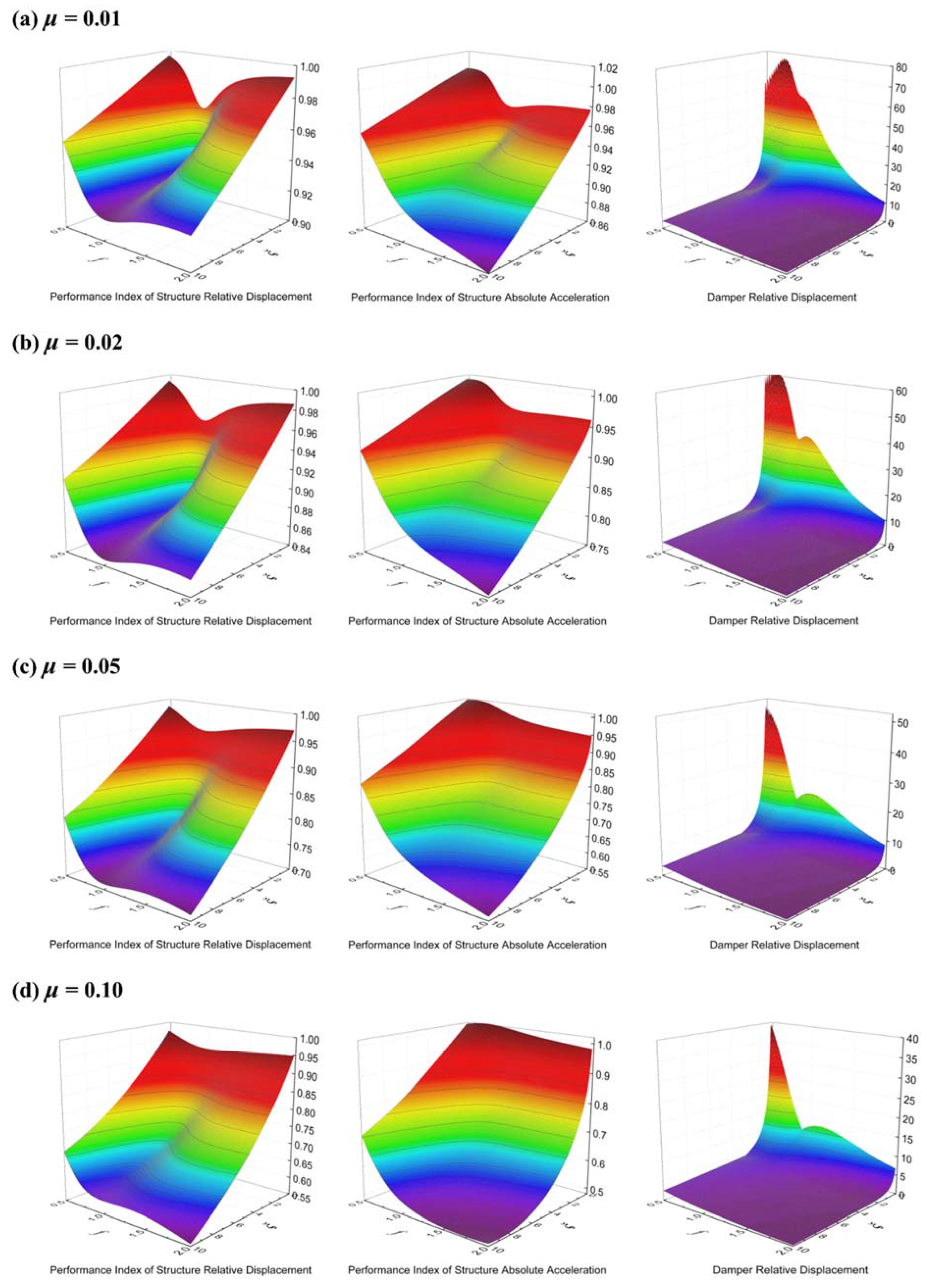
The seismic mitigation performance in structural displacement and acceleration, as well as the damper relative displacement for cases with mass ratios μ of 0.01, 0.02, 0.05, and 0.10, are illustrated in Figure 2. The mitigation effect for the relative displacement is the most widely focused performance measure for T M D systems for building structures. It is demonstrated in Figure 2, that for all cases, the T M D system does not have “the optimal” relative displacement mitigation effect. Instead, there is a “valley” like path on the surface of the relative displacement mitigation effect, i.e., given a fixed damping ratio ξ , an optimal frequency ratio f that leads to the highest relative displacement mitigation effect that can be found. This is different from the typical observations for TMD systems modeled as a 2DOF system mounted on rigid bases. With the increase of the mass ratio μ , the “valley” becomes shallower, which indicates that the optimality of the optimal design relative to the rest of the designs given the damping ratio, becomes less. This observation, on the other hand, implies that TMD systems with larger mass ratios may have higher robustness to detuning.
For the acceleration mitigation effects similar to the displacement mitigation effects, no apparent global optimal design can be observed, while a “valley” like path exists where the optimal f given ξ can be determined. However, the “valley” like path disappears in the cases with a higher mass ratio, i.e., it is seen from the results that for specific ξ , more effective acceleration mitigation can be observed with the increase of frequency ratio f , until when f is greater than 1.0, where the performance stabilizes. Therefore, for design purposes, it is still possible to select a practical f with the stabilized performance given ξ .
Finally, it is observed from the relative displacement results that the T M D relative displacement is much lower when it is with higher TMD damping ratios. This agrees with the previous research [23], that TMD damping can control relative displacements. While at the same time, it can be observed that there is a “ridge” like path, corresponding to the optimal frequency at all damping ratios. This should be attributed to the fact that the TMD is well-tuned at the optimal designs given ξ , where the TMD consequently experiences the largest relative displacement and thus, dissipates the most energy.

3.2. Design Formulae

Based on the seismic mitigation performance, a set of design formulae was obtained based on numerical optimization and fitting. In particular, the design problem is first formulated as an optimization problem, with respect to the frequency ratio f given damping ratios ξ . The problem is subsequently solved, and numerical fitting is further carried out to establish a simple relationship between the optimal frequency ratio f ^ and the corresponding ξ , i.e., the mathematical description of the “valley” like path.
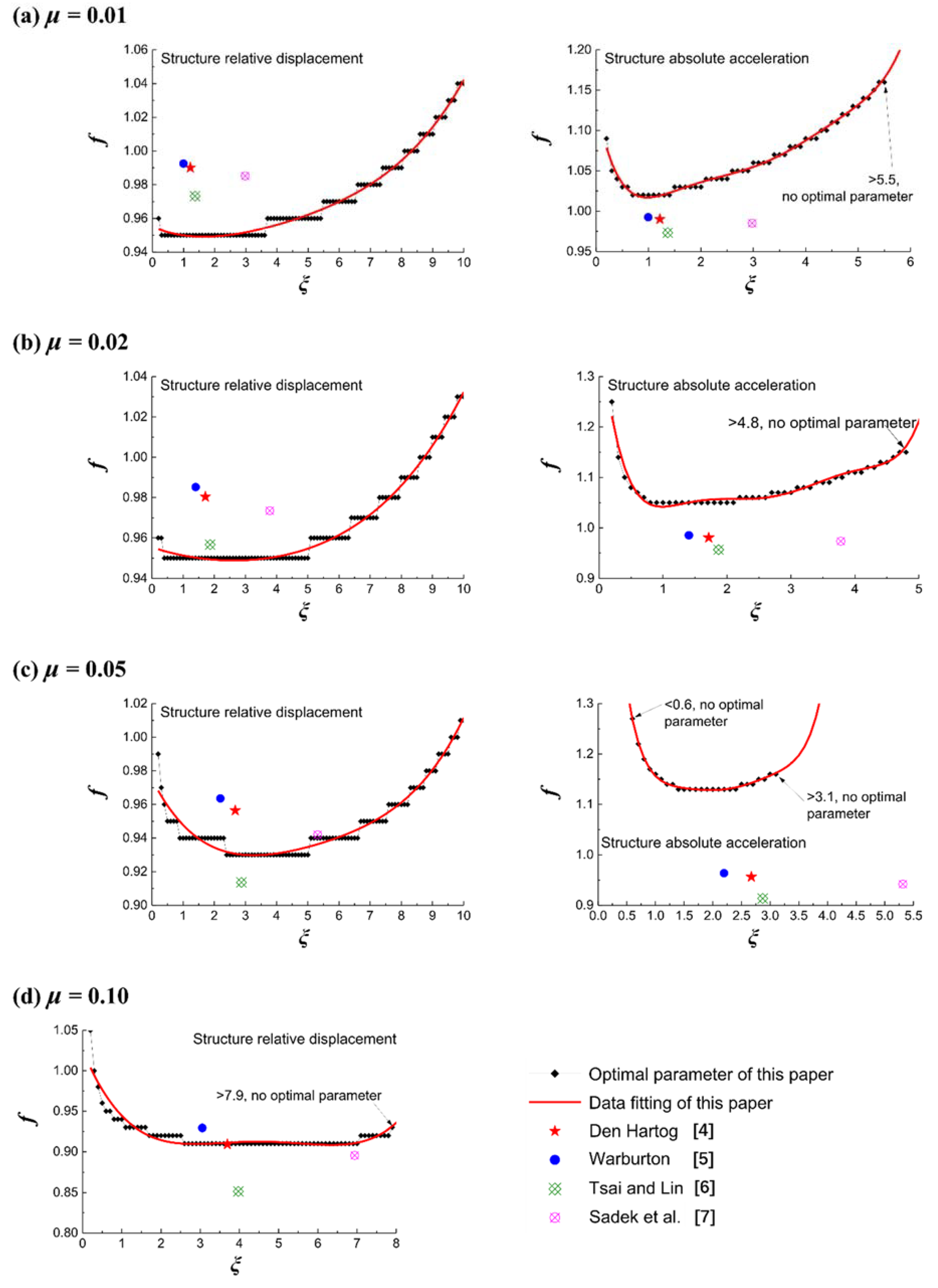
Traditional TMD design problems are typically considered as an optimization problem with a design space of f ^ , ξ . However, this consideration is not suitable for this work because the problem considered here does not have a global or local optimal design in f ^ , ξ . Meanwhile, in practical engineering, the damping is determined not only based on seismic mitigation performances, but also on the T M D stroke limits as well as the costs [23]. Taking all the aspects into consideration of an optimization problem can be involving, as the accurate quantification of costs is not trivial work. Within this context, it is proposed to determine an appropriate ξ as a trade-off among T M D performances, strokes, and costs through, e.g., engineering experience. Further, f ^ is determined based on ξ , which requires the design formulae f ^ ξ . To this end, for a set of ξ , f ^ is obtained by a grid search, providing the data in the form of value pairs of f ^ and ξ . The mathematical description of f ^ ξ was calibrated through the widely used polynomial regression of the form, as in Equation (31):
f ^ = ψ 6 ξ 6 + ψ 5 ξ 5 + ψ 4 ξ 4 + ψ 3 ξ 3 + ψ 2 ξ 2 + ψ 1 ξ 1 + ψ 0
where the coefficients for cases with μ of 0.01, 0.02, 0.05, and 0.10 with the consideration of both the structural relative displacement and absolute acceleration are shown in Table 1. The data and the curve by the calibrated formulae are shown comparatively in Figure 3, along with the four traditional design formulae. It should be mentioned that the results for the case with μ of 0.10 considering absolute acceleration are not shown because the T M D performance never stabilizes and f ^ cannot be determined. This implies that for cases with relatively large mass ratios, it is suggested to use a reasonable higher T M D frequency ratio for the purpose of absolute acceleration mitigation. It is seen that the calibrated formulae match perfectly well with the data, in all cases. At the same time, it should be noted that the traditional design formulae are in general, far away from the calibrated formulae, i.e., the “valley” like path, indicating the sub-optimality of the resultant designs due to the inability of considering SSI effects.
.
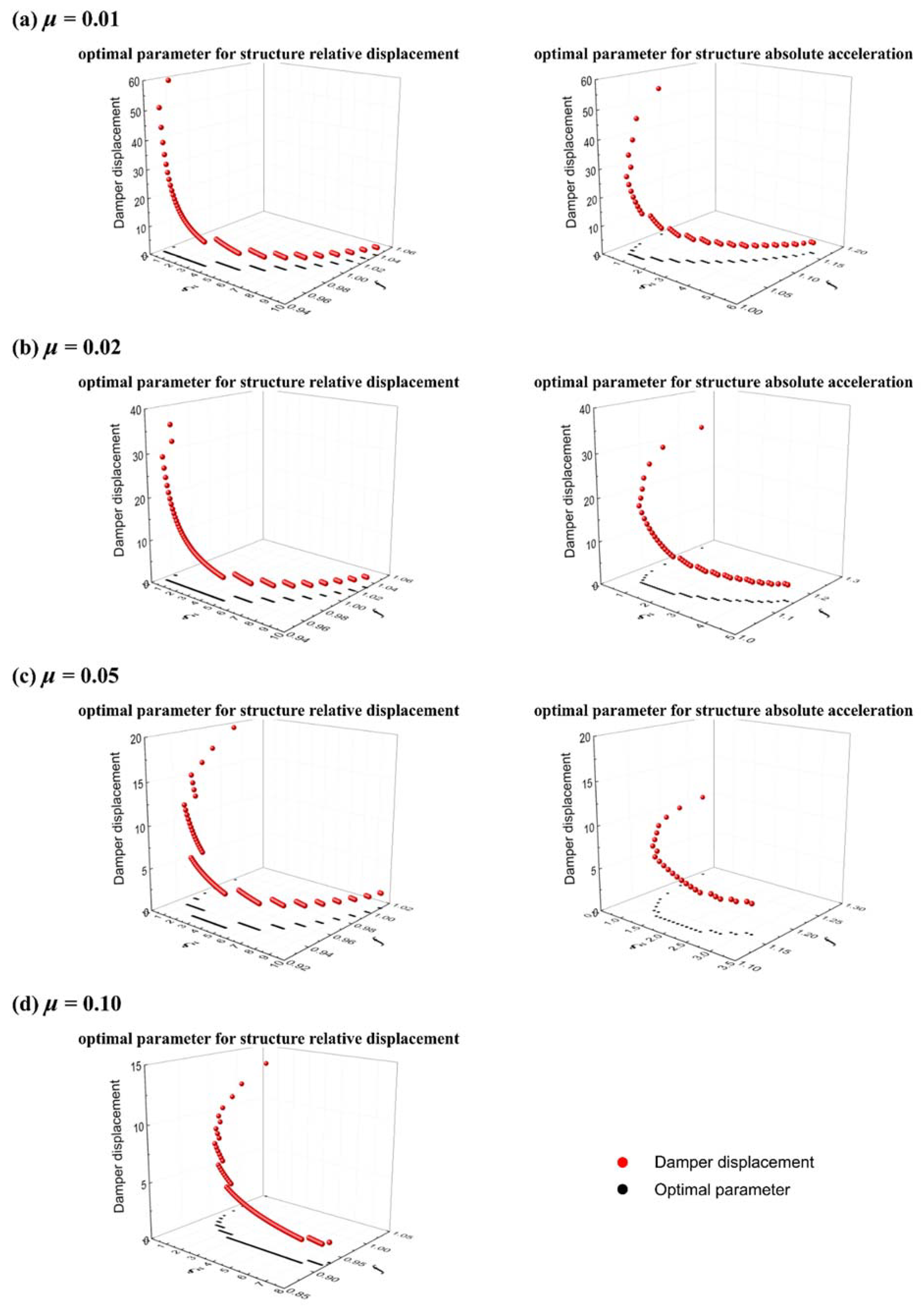
To facilitate the practical applications, the T M D stroke is shown in Figure 4, along with the f ^ for each given ξ . It is seen that for all cases, with the increase of ξ , the T M D strokes in all four cases are decreasing rapidly at the very beginning. When the ξ is relatively high, the decline of the T M D strokes becomes slower. This indicates that it is more effective and economical to control T M D strokes by increasing damping when the damping ratio is relatively low, e.g., less than 3%. On the other hand, for cases where a ξ larger than 3% is needed, the T M D strokes are in general too small already, and mitigation by T M D may no longer be a good design. In engineering practices, TMDs can be designed by:
(1)
Based on T M D stroke and installation budget limits, design the damping system for the T M D .
(2)
Estimate the ξ of the damping system and obtain f ^ ξ .
(3)
Check the mitigation performance as well as practicability of the T M D system.

4. Case Study

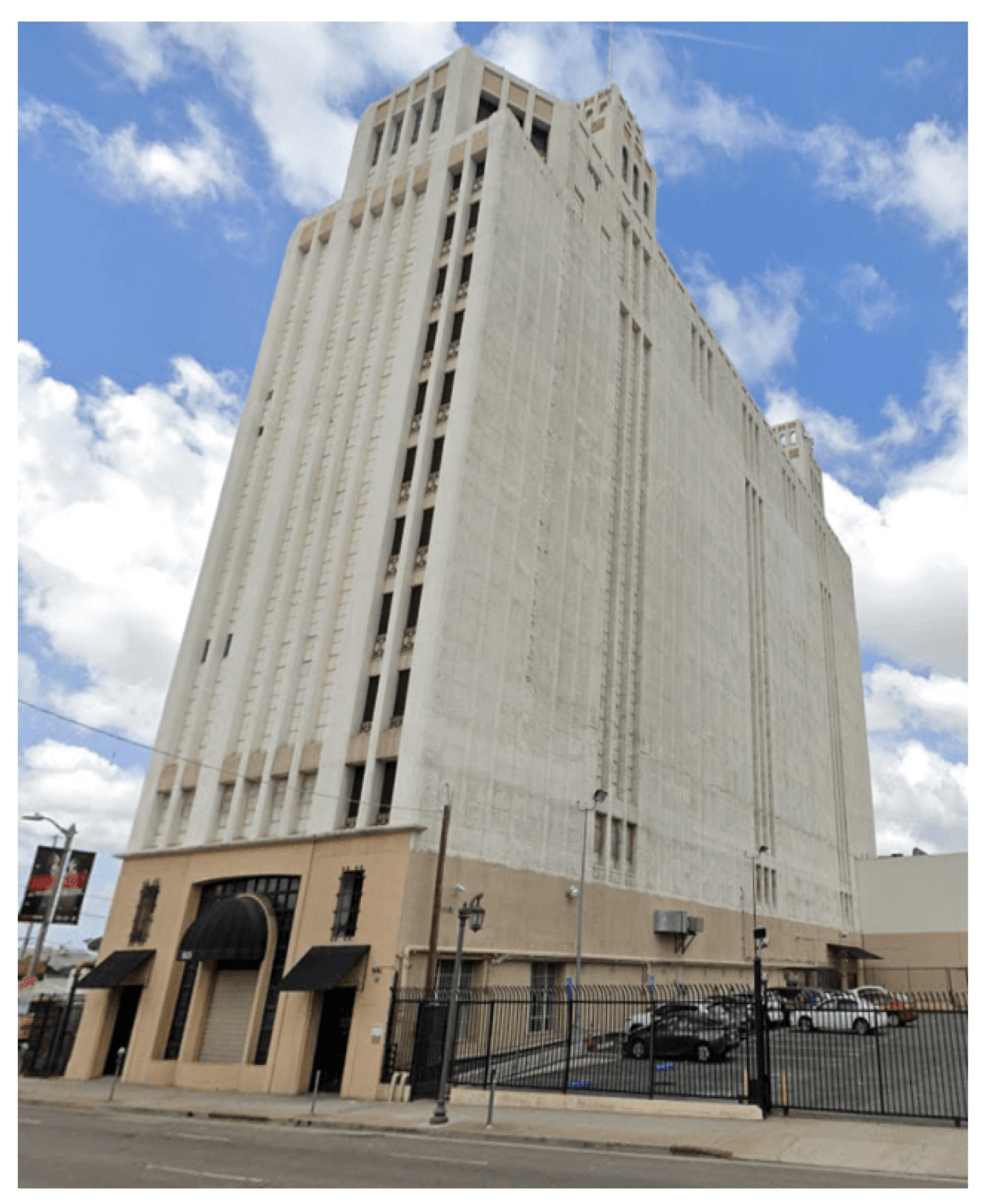
As shown in Figure 5, the Hollywood Storage Building, built in 1930 in Los Angeles, is a 14-story reinforced concrete building. The strong-motion seismographs were installed in the building in 1933, and the acceleration time histories of this building during many earthquakes were recorded [36,37], which makes this building a good example for investigating SSI problems [38,39,40,41]. The length of the building in the EW direction is 66.29 m, the width in the NS direction is 15.54 m, and the height is 45.3 m. The translation fundamental frequency in the EW direction is 1.78 Hz [36]. Through the investigation of Duke et al. [38], the foundation of this building can be regarded as a rigid semi-cylinder with a radius of a = 7.92 m (about half of the building width 15.54 m) and a mass ratio of M 0 / M S = 1 and M b / M S = 1.4. The mass density (on average) of the soil is 1.84 × 10³ kg/m3 [39]. In addition, the parameter ηb takes 1/6, which fits typical engineering cases.
We modeled the building as an SDOF oscillator, standing on a semi-circular rigid foundation with a = 7.92 m, M 0 / M S = 1, and M b / M S = 1.4. To meet the EW translation fundamental frequency during earthquakes, the natural frequency of the SDOF oscillator is set to be 1.78 Hz. The shear wave velocity and mass density are β = 243.84 m/s and ρ = 1.84 × 10 3 kg/m3, as in [38,39].
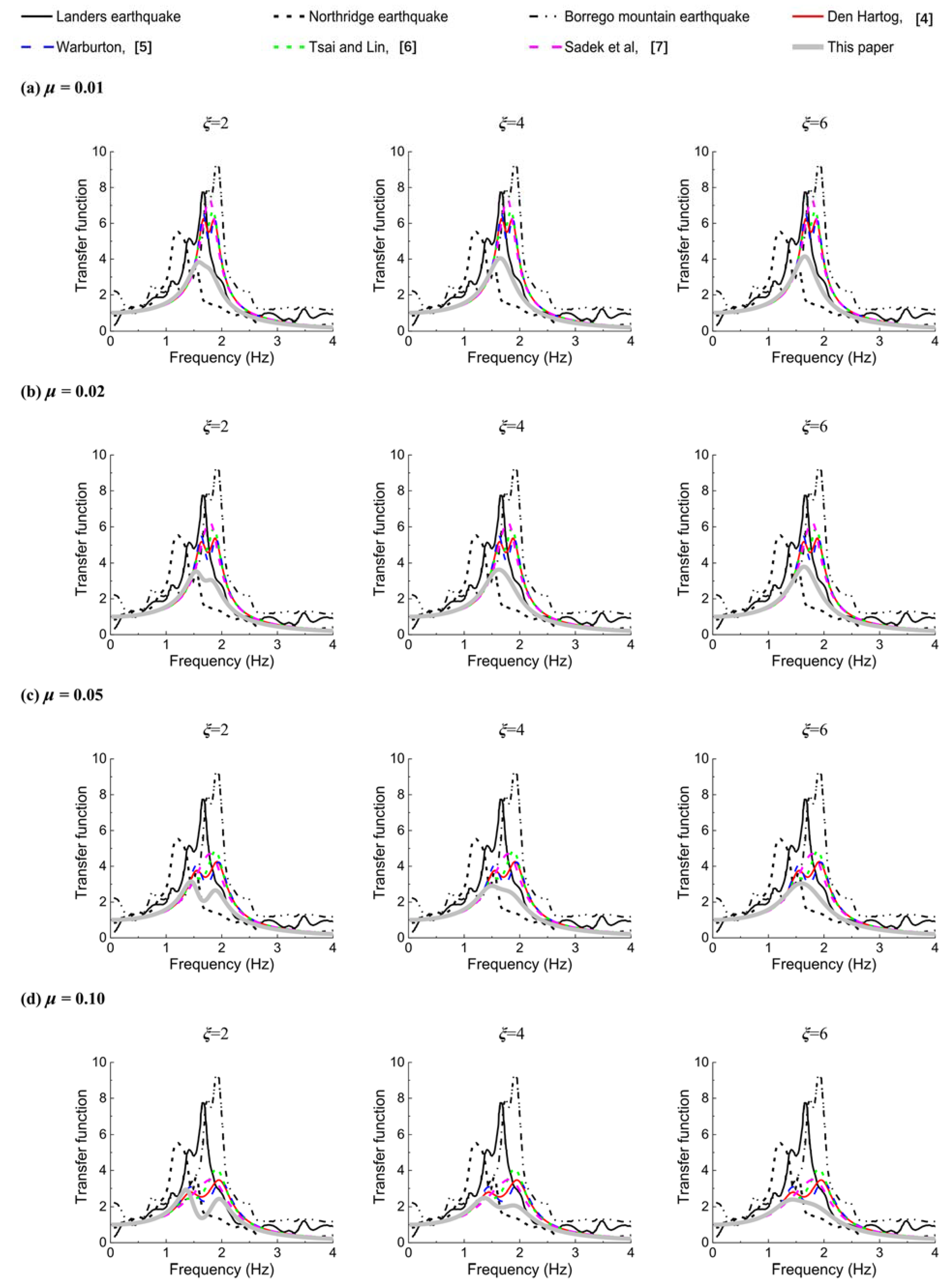
In this case, a TMD was hypothetically introduced into the building for seismic mitigation purposes. Designs of the TMD were obtained through the four traditional methods as well as the proposed design framework. In particular, combinations with μ of 0.01, 0.02, 0.05, 0.10, and ξ of 2, 4, and 6 are considered to give a throughout illustration for various design cases. Subsequently, f ^ for each of the parameter combinations is determined through the proposed design scheme, as well as through the traditional design formulae. The transfer functions of the building displacements were obtained through the soil-structure-TMD interaction model derived in Section 2. Subsequently, with reference to the observations of this building in the Landers earthquake, the Northridge earthquake, and the Borrego Mountain earthquake (considering the SSI effect but no T M D effect), the TMD performance was comparatively evaluated and shown in Figure 6. The enlarged views of the range around the resonant peak for each of the cases are added to their upper-right corner. It is seen that in all cases, the transfer function value determined by the proposed design formulae is significantly less than that of the original structure or the traditional design formulae, which indicates the effectiveness of the proposed design formulae. Meanwhile, while the transfer function value of the traditional design formulae is sometimes higher than that of the original structure, meaning these designs could amplify responses and cause detrimental effects, the transfer function value of the proposed design formulae is, on the contrary, almost always lower than that of the original structure, indicating the robustness of the proposed design formulae to loads of various frequency contents. In addition, with the mass ratio increasing, the difference among different designs becomes smaller, which is reasonable since the T M D system with a larger mass ratio is more robust, i.e., less sensitive to different designs.
Overall, through this real existing case study, the proposed design formulae are shown to be highly effective and robust in loads of various frequency contents. Moreover, its simple form enables the design formulae to be easily used. These excellent characteristics show the great promise of the proposed design formulae in practical engineering.

5. Conclusions

This paper presented a novel design scheme for building a TMD system considering the SSI effect, based on an analytic model of a TMD system standing on a rigid semi-circular foundation embedded in the half-space and subjected to the out-of-plane SH seismic wave. It is proposed to first allow designers to select an appropriate damping ratio as a trade-off among TMD mitigation performance, strokes, and cost, and subsequently tune the TMD through the design formulae. With seismic mitigation performances in the structural displacement and acceleration of the TMD system for various mass ratios being thoroughly discussed, optimization problems are formulated for each given damping ratio and solved for optimal frequency ratios in each of the mass ratio cases. Numerical fitting is subsequently carried out to identify the design formulae for the optimal frequency ratios versus damping ratios. Meanwhile, the TMD strokes of the optimal designs have been investigated to facilitate the determination of TMD damping ratios. Based on the research, the following conclusions can be drawn:
(1)
The proposed design formulae are easy-to-use while being highly effective and robust to loads of various frequency contents, compared with the traditional design formulae.
(2)
For the problem setup in this research, with the consideration of SSI, a global optimal design may not exist. Therefore, for the related optimization problems, extra constraints, e.g., selected damping ratios, are suggested to be considered.
(3)
Similar to those observed in cases without SSI, TMD systems with larger mass ratios are more robust to the changes in damping ratio and frequency ratio, while larger TMD damping would lead to a lower TMD stroke.
It should be mentioned that the problem investigated involves an SDOF system equipped with a single TMD. The authors are working on extending this work to MDOF systems with single or multiple TMDs, to consider the effects of higher-order modes of main structures, as well as the application of multiple TMDs. Besides, due to its harmonic operation in this paper, with earthquakes far from the resonance frequency, a lower TMD performance might happen. This is not a weak point of the developed approach in this paper but rather depends on the nature of the TMD.

Author Contributions

L.J.: Conceptualization Methodology, Validation, Formal analysis, Visualization, Writing—original draft—review & editing. B.L.: Validation, Formal analysis, Software, Investigation, Supervision, Writing—review & editing. S.L.: Visualization, Data curation. G.L.: Validation, Data curation. All authors have read and agreed to the published version of the manuscript.

Funding

This study was funded by the Special Fund of the Institute of Geophysics China Earthquake Administration [Grant No. DQJB21K45] and the China Postdoctoral Science Foundation [Grant No. 2022M712943].

Data Availability Statement

If readers require data from this article, please contact the corresponding author.

Conflicts of Interest

There are no competing interest that can influence the research published in this article.

References

  1. Sladek, J.R.; Klingner, R.E. Effect of tuned-mass dampers on seismic response. J. Struct. Eng. 1983, 109, 2004–2009. [Google Scholar] [CrossRef]
  2. Soto, M.G.; Adeli, H. Tuned mass dampers. Arch. Comput. Methods Eng. 2013, 20, 419–431. [Google Scholar] [CrossRef]
  3. Lu, X.; Zhang, Q.; Weng, D.; Zhou, Z.; Wang, S.; Mahin, S.A.; Ding, S.; Qian, F. Improving performance of a super tall building using a new eddy-current tuned mass damper. Struct. Control. Health Monit. 2017, 24, e1882. [Google Scholar] [CrossRef]
  4. Den Hartog, J.P. Mechanical Vibrations; Courier Corporation: Chelmsford, MA, USA, 1985. [Google Scholar]
  5. Warburton, G.B. Optimum absorber parameters for various combinations of response and excitation parameters. Earthq. Eng. Struct. Dyn. 1982, 10, 381–401. [Google Scholar] [CrossRef]
  6. Tsai, H.C.; Lin, G.C. Optimum tuned-mass dampers for minimizing steady-state response of support-excited and damped systems. Earthq. Eng. Struct. Dyn. 1993, 22, 957–973. [Google Scholar] [CrossRef]
  7. Sadek, F.; Mohraz, B.; Taylor, A.W.; Chung, R.M. A method of estimating the parameters of tuned mass dampers for seismic applications. Earthq. Eng. Struct. Dyn. 1997, 26, 617–635. [Google Scholar] [CrossRef]
  8. Veletsos, A.S. Dynamics of structure-foundation systems. In Structural and Geotechnical Mechanics; Hall, W.J., Ed.; Prentice-Hall Inc.: Englewood Cliffs, NJ, USA, 1977; pp. 333–361. [Google Scholar]
  9. Wolf, J.P. Dynamic Soil–Structure Interaction; Prentice-Hall: Englewood Cliffs, NJ, USA, 1985. [Google Scholar]
  10. Domenico, D.; Impollonia, N.; Ricciardi, G. Soil-dependent optimum design of a new passive vibration control system combining seismic base isolation with tuned inerter damper. Soil Dyn. Earthq. Eng. 2018, 105, 37–53. [Google Scholar] [CrossRef]
  11. Abd-Elhamed, A.; Mahmoud, S. Simulation analysis of TMD controlled building subjected to far- and near-fault records considering soil-structure interaction. J. Build. Eng. 2019, 26, 100930. [Google Scholar] [CrossRef]
  12. Boksmati, J.I.; Madabhushi, G.S.; Thusyanthan, I.N. Dynamic soil-structure interaction of a shallow founded shear frame and a frame equipped with viscous dampers under seismic loading. Eng. Struct. 2021, 227, 111388. [Google Scholar] [CrossRef]
  13. Wu, J.; Chen, G.; Lou, M. Seismic effectiveness of tuned mass dampers considering soil–structure interaction. Earthq. Eng. Struct. Dyn. 1999, 28, 1219–1233. [Google Scholar] [CrossRef]
  14. Ghosh, A.; Basu, B. Effect of soil interaction on the performance of tuned mass dampers for seismic applications. J. Sound Vib. 2004, 3, 1079–1090. [Google Scholar] [CrossRef]
  15. Jabary, R.N.; Madabhushi, S.P. Tuned mass damper effects on the response of multi-storied structures observed in geotechnical centrifuge tests. Soil Dyn. Earthq. Eng. 2015, 77, 373–380. [Google Scholar] [CrossRef]
  16. Khatibinia, M.; Gholami, H.; Labbafi, S.F. Multi-objective optimization of tuned mass dampers considering soil-structure interaction. Int. J. Optim. Civ. Eng. 2016, 6, 595–610. [Google Scholar]
  17. Khoshnoudian, F.; Ziaei, R.; Ayyobi, P. Effects of nonlinear soil-structure interaction on the seismic response of structure-TMD systems subjected to near-field earthquakes. Bull. Earthq. Eng. 2017, 15, 199–226. [Google Scholar] [CrossRef]
  18. Ding, H.; Kaup, A.; Wang, J.; Lu, L.; Altay, O. Real-time hybrid simulation framework for the investigation of soil-structure interaction effects on the vibration control performance of shape memory alloys. Eng. Struct. 2021, 243, 112621. [Google Scholar] [CrossRef]
  19. Mortezaie, H.; Rezaie, F. Effect of soil in controlling the seismic response of three-dimensional PBPD high-rise concrete structures. Struct. Eng. Mech. 2018, 66, 217–227. [Google Scholar]
  20. Zhou, Z.; Wei, X.; Lu, Z.; Jeremic, B. Influence of soil-structure interaction on performance of a super tall building using a new eddy-current tuned mass damper. Struct. Des. Tall Spec. Build. 2018, 27, e1501. [Google Scholar] [CrossRef] [Green Version]
  21. Wang, J.F.; Lin, C.C. Seismic performance of multiple tuned mass dampers for soil-irregular building interaction systems. Int. J. Solids Struct. 2005, 42, 5536–5554. [Google Scholar] [CrossRef]
  22. Salvi, J.; Pioldi, F.; Rizzi, E. Optimum tuned mass dampers under seismic soil-structure interaction. Soil Dyn. Earthq. Eng. 2018, 114, 576–597. [Google Scholar] [CrossRef]
  23. Dai, K.; Li, B.; Wang, J.; Li, A.; Li, H.; Li, J.; Tesfamariam, S. Optimal probability-based partial mass isolation of elevated coal scuttle in thermal power plant building. Struct. Des. Tall Spec. Build. 2018, 27, e1477. [Google Scholar] [CrossRef]
  24. Tavakolinia, M.; Ch Basim, M. Performance-based optimum tuning of tuned mass dampers on steel moment frames for seismic applications using the endurance time method. Earthq. Eng. Struct. Dyn. 2021, 50, 3646–3669. [Google Scholar] [CrossRef]
  25. Farshidianfar, A.; Soheili, S. Ant colony optimization of tuned mass dampers for earthquake oscillations of high-rise structures including soil–structure interaction. Soil Dyn. Earthq. Eng. 2013, 51, 14–22. [Google Scholar] [CrossRef]
  26. Bekdaş, G.; Nigdeli, S.M. Metaheuristic based optimization of tuned mass dampers under earthquake excitation by considering soil-structure interaction. Soil Dyn. Earthq. Eng. 2017, 92, 443–461. [Google Scholar] [CrossRef]
  27. Bekdaş, G.; Kayabekir, A.E.; Nigdeli, S.M.; Toklu, Y.C. Tranfer function amplitude minimization for structures with tuned mass dampers considering soil-structure interaction. Soil Dyn. Earthq. Eng. 2019, 116, 552–562. [Google Scholar] [CrossRef]
  28. Fu, J.; Liang, J. Performance degradation of tuned-mass-dampers arising from ignoring soil-structure interaction effects. Soil Dyn. Earthq. Eng. 2019, 125, 105701. [Google Scholar]
  29. Liu, S.; Lu, Z.; Li, P.; Ding, S.; Wan, F. Shaking table test and numerical simulation of eddy-current tuned mass damper for structural seismic control considering soil-structure interaction. Eng. Struct. 2020, 212, 110531. [Google Scholar]
  30. Nigdeli, S.M.; Bekdaş, G. Optimum design of multiple positioned tuned mass dampers for structures constrained with axial force capacity. Struct. Des. Tall Spec. Build. 2019, 28, e1593. [Google Scholar] [CrossRef]
  31. Jin, L.; Liang, J. Dynamic soil-structure interaction with a flexible foundation embedded in a half-space: Closed-form analytical solution for incident plane SH-waves. J. Earthq. Eng. 2021, 25, 1565–1589. [Google Scholar] [CrossRef]
  32. Trifunac, M.D. Dynamic interaction of a shear wall with the soil for incident plane SH Waves. Bull. Seismol. Soc. Am. 1972, 62, 62–83. [Google Scholar] [CrossRef]
  33. ASCE/SEI 7-16; Minimum Design Loads and Associated Criteria for Buildings and Other Structures. American Society of Civil Engineers (ASCE): Reston, VA, USA, 2017.
  34. Zuo, L.; Nayfeh, S.A. Optimization of the individual stiffness and damping parameters in multiple-tuned-mass-damper systems. J. Vib. Acoust. 2005, 127, 77–83. [Google Scholar] [CrossRef]
  35. Todorovska, M.I.; Trifunac, M.D. The system damping, the system frequency and the system response peak amplitudes during in-plane building-soil interaction. Earthq. Eng. Struct. Dyn. 1992, 21, 127–144. [Google Scholar] [CrossRef]
  36. Trifunac, M.D.; Hao, T.Y.; Todorovska, M.I. Response of a 14-Story Reinforced Concrete Structure to Nine Earthquakes: 61 Years of Observation in the Hollywood Storage Building; Report CE01-02; Department of Civil Engineering, University of Southern California: Los Angeles, CA, USA, 2001. [Google Scholar]
  37. Todorovska, M.I. Full-scale experimental studies of soil-structure interaction. ISET J. Earthq. Technol. 2002, 39, 139–165. [Google Scholar]
  38. Duke, C.M.; Luco, J.E.; Carriveau, A.R.; Hradilex, P.J.; Lastrico, R.; Ostrom, D. Strong earthquake motion and site conditions: Hollywood. Bull. Seismol. Soc. Am. 1970, 60, 1271–1289. [Google Scholar] [CrossRef]
  39. Crouse, C.B.; Jennings, P.C. Soil-structure interaction during the San Fernando earthquake. Bull. Seismol. Soc. Am. 1975, 65, 13–36. [Google Scholar] [CrossRef]
  40. Liang, J.; Fu, J.; Todorovska, M.I.; Trifunac, M.D. Effects of the site dynamic characteristics on soil-structure interaction (I): Incident SH-waves. Soil Dyn. Earthq. Eng. 2013, 44, 27–37. [Google Scholar] [CrossRef]
  41. Liang, J.; Fu, J.; Todorovska, M.I.; Trifunac, M.D. Effects of the site dynamic characteristics on soil-structure interaction (II): Incident P and SV waves. Soil Dyn. Earthq. Eng. 2013, 51, 58–76. [Google Scholar] [CrossRef]
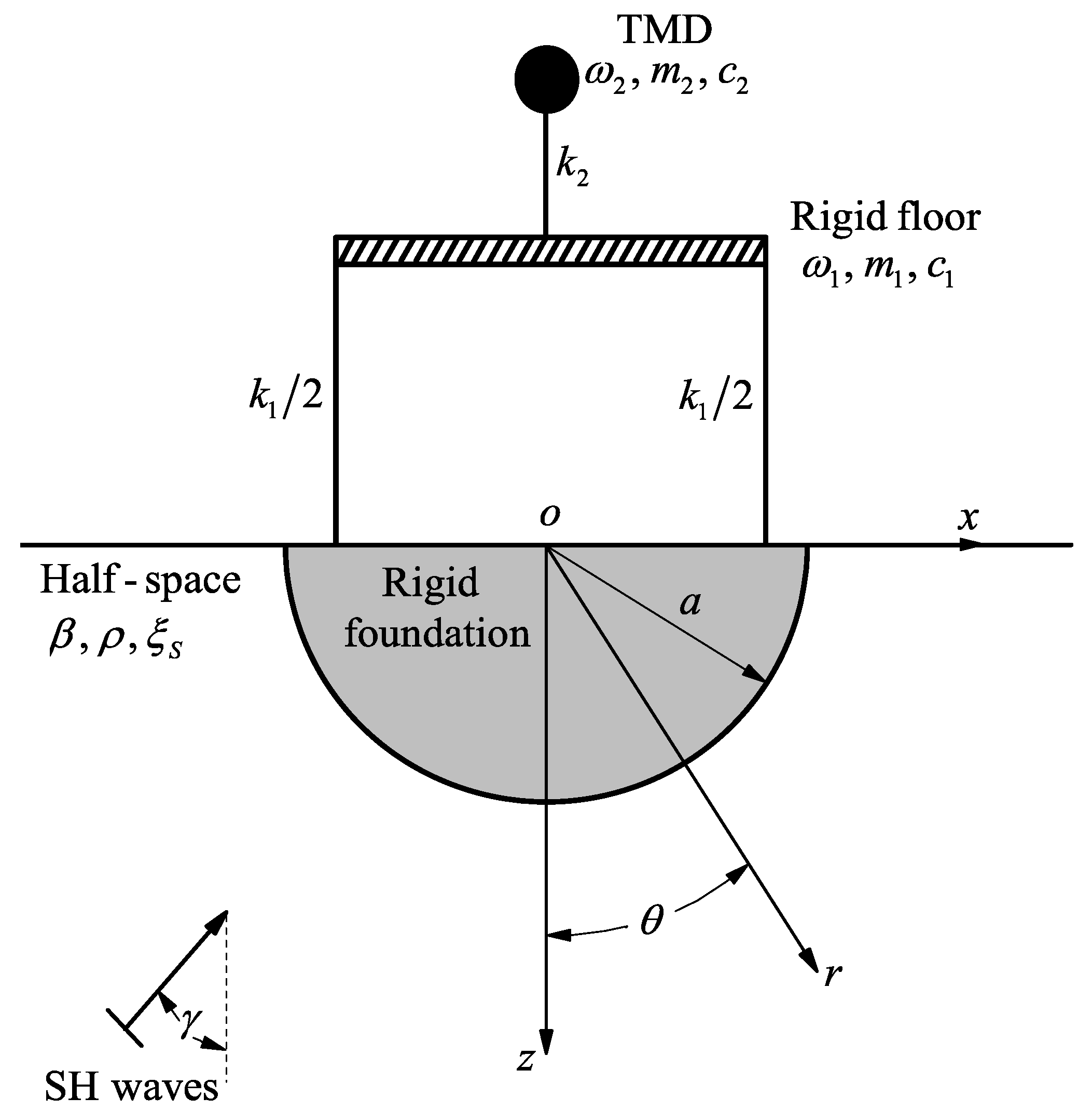
Figure 1. The soil-structure-TMD seismic interaction model under the excitation of plane SH seismic waves.
Buildings 13 00017 g001
Figure 2. Seismic mitigation performance in structural displacement and acceleration, as well as damper relative displacement for cases with the mass ratio of (a) 0.01; (b) 0.02; (c) 0.05; (d) 0.10.
Buildings 13 00017 g002
Figure 3. Data and calibrated formulae for optimal frequency ratios and damping ratios as well as traditional design formulae for the mass ratio of (a) 0.01; (b) 0.02; (c) 0.05; (d) 0.10.
Buildings 13 00017 g003
Figure 4. TMD stroke (damper displacement relative to the main structure) with respect to optimal frequency ratios given damping ratios for the mass ratio of (a) 0.01; (b) 0.02; (c) 0.05; (d) 0.10. The horizontal axes f is the ratio between the TMD natural frequency and structure natural frequency; the horizontal axes ξ is the ratio between TMD damping ratio and structure damping ratio.
Buildings 13 00017 g004
Figure 5. Hollywood Storage Building.
Buildings 13 00017 g005
Figure 6. The transfer function amplitudes of the relative displacement between the roof center and the basement center during the Landers earthquake, Northridge earthquake, and Borrego Mountain earthquake for mass ratios of (a) 0.01; (b) 0.02; (c) 0.05; (d) 0.10, with damping ratios of 2 (column 1), 4 (column 2), and 6 (column 3).
Buildings 13 00017 g006
Table 1. Coefficients of calibrated design formulae f ^ ξ .
Optimal Minimizing μ ψ 6 ψ 5 ψ 4 ψ 3 ψ 2 ψ 1 ψ 0
Displacement0.01002.39 × 10−5−4.02 × 10−43.31 × 10−3−8.08 × 10−30.9551
0.02008.23 × 10−6−6.73 × 10−51.14 × 10−3−5.16 × 10−30.9554
0.05005.58 × 10−5−1.17 × 10−30.0101−0.03630.9751
0.10003.64 × 10−4−6.65 × 10−30.0434−0.11881.0260
Acceleration0.013.21 × 10−4−6.19 × 10−30.0472−0.18000.3599−0.33721.1330
0.022.39 × 10−3−0.03920.2543−0.82271.3895−1.14361.4011
0.050.0102−0.13780.7580−2.17063.4322−2.87142.1358
0.10-------
Note: For acceleration response in μ = 0.10, the “ridge” like path does not exist.
Disclaimer/Publisher’s Note: The statements, opinions and data contained in all publications are solely those of the individual author(s) and contributor(s) and not of MDPI and/or the editor(s). MDPI and/or the editor(s) disclaim responsibility for any injury to people or property resulting from any ideas, methods, instructions or products referred to in the content.