Article

The Interfacial Friction Loss of Prestressed Carbon-Fiber Tendons in a Bending State

1
School of Civil & Environmental Engineering and Geography Science, Ningbo University, Ningbo 315211, China
2
Ningbo Communications Planning Institute, First Design Institute, Ningbo 315000, China
*
Authors to whom correspondence should be addressed.
Buildings 2023, 13(1), 99; https://doi.org/10.3390/buildings13010099
Submission received: 14 November 2022 / Revised: 18 December 2022 / Accepted: 26 December 2022 / Published: 30 December 2022
(This article belongs to the Special Issue New and Future Progress for Concrete Structures)

Abstract

:
Carbon-fiber reinforced plastic (CFRP) is ideal for bridge reinforcement due to its high strength, light weight, and corrosion resistance. Studies on the friction loss of CFRP tendons in a bending state form an important part of advancing the application of CFRP materials to external prestressing strengthening technology. To understand the magnitude and variation of interfacial friction loss of prestressed CFRP tendons under bending conditions, 12 single-bending prestressing tension tests and 4 three-consecutive-bending prestressing tension tests were conducted in this study. Two bending radii of 1.5 m and 2 m, two bending angles of 20° and 30°, and three contact surfaces with different friction coefficients were selected for the steering block condition to measure the friction loss under each stage of tensioning prestress. On this basis, a model for calculating the friction loss rate on the surface of prestressed CFRP tendons was derived for the change of contact stress between CFRP tendons and deflectors during the installation and tensioning stages. The results show that the friction loss of external prestressed CFRP tendons is mainly related to four external factors: bending radius, steering angle, friction coefficient, and the magnitude of tensioning prestress; with the increase of prestress, the friction loss rate goes through three stages, the rising stage, the falling stage, and the stable stage; in the process of friction loss rate change, the main influencing factor controlling the magnitude of friction loss rate changes from bending radius to steering angle. In the theoretical calculation model of friction loss rate, the calculation model of the prestressed CFRP tendons under multiple successive bends can be simplified to a combination of several calculation models for a single bend. This study provides a reference for the engineering field of strengthening reinforced concrete (RC) beams using external prestressed CFRP tendons.

1. Introduction

Currently, external prestressing technology is a good solution to compensate for the loss of prestress in concrete bridges [1,2]. CFRP materials have the advantages of good corrosion resistance, high tensile strength, and lightweight [3,4,5,6,7,8,9]; they have been gradually replacing steel strands as the main structural element for external prestressing reinforcement in civil engineering [5,10,11,12,13,14,15]. The most mainstream reinforcement method of the in vitro prestressing technology is to install the CFRP tendons on the reinforced concrete (RC) beams through anchorage devices at both ends and apply prestressing along the direction of the CFRP fibers [13].
Such materials are used in the external prestressing reinforcement technology. Taljsten et al. [16] achieved an increase in fatigue life by bonding CFRP laminates to the steel surface, while the addition of prestressing increased the reinforcement effect by a factor of four. Aslam et al. [17] showed that prestressed FRP was an effective material for strengthening deteriorated structures, and also provided a comprehensive review of the buckling behaviors of RC beams strengthened with prestressed FRP. The review covered the near surface mounting (NSM), externally bonded reinforcement (EBR), and externally post-tensioned techniques (EPT), and highlighted the corresponding advantages and disadvantages. Yang et al. [18] carried out flexural tests and finite element analysis on FRP-reinforced beams strengthened by different prestressing reinforcement methods and found that the external unbonded prestressing method was more effective in strengthening RC beams than the external bonded prestressing method. Wang et al. [19] investigated the buckling behavior and long-term prestress losses in reinforced concrete beams strengthened with post-tensioned CFRP plates. The tests showed that the prestress loss in CFRP plates in the post-tensioned system was due to is anchorage (about 12.6% to 18.2% of the initial prestress), while the time loss due to creep and shrinkage of the concrete and relaxation loss in the CFRP plates was relatively small (about 2.3% to 3.9% of the initial prestress); Jia et al. [20] performed external prestressed CFRP tendon reinforcement on seven T-beams, where the fully prestressed beams withstood 2 million cycles of loading in fatigue tests, while the partially prestressed beams failed after about 97,200 cycles, and the higher effective prestressing stresses were beneficial in maintaining the beam stiffness.
Ng et al. [21] investigated the effect of external unbonded prestressing on the shear behavior of concrete beams The test results showed that external prestressing reduced the span-to-depth ratio (a/d, where a is span and d is depth) and significantly strengthened the shear capacity of concrete beams; Le et al. [22] constructed four large T-shaped segmental concrete beams with different types of nodes and reinforcement bundle materials (steel/CFRP tendon bundles) and tested them in cycles under four-point loading, and the test results showed that CFRP tendons can replace steel bars in segmented concrete beams as external prestressing material. All tested beams showed excellent performance in terms of load-carrying capacity and ductility. Li et al. [23] conducted fatigue loading tests on three continuous concrete beams reinforced by externally prestressed CFRP tendons and investigated the effects of different load levels on stiffness degradation and fatigue life, and an analytic model considering load levels was proposed to calculate residual stiffness and predict stiffness degradation, which was in good agreement with the test results. Lou et al. [24] conducted a numerical study of T-beams reinforced with extracorporeal prestressed FRP materials and compared the results with those using conventional reinforcement methods. The analysis showed that the external FRP bundles had lower flexural strength but better ductility than the external steel bundles. The type of external reinforcement had no binding effect on the redistribution of bending moments in continuous beams.
In summary, the application of CFRP materials in the field of external prestressing reinforcement of bridges can effectively increase the ultimate load of RC beams, delay the occurrence of cracks, and increase the fatigue life of the beams [18]. At the same time, among the many external prestressing methods, external unbonded prestressing has become a common means of strengthening damaged buildings with its convenience and good reinforcement effect [25,26,27]. In fact, the steering system of the externally prestressed tendon bundles is a key part of the externally prestressed reinforcement technology, which is directly related to the force condition of the externally prestressed tendon bundles [28,29,30,31]. In the field of prestressed strand research, it was recognized earlier that its interfacial friction loss directly affected the application effect of the prestressed reinforcement technology [32,33,34,35]. Therefore, in order to increase the reinforcement style of CFRP tendon bundles in the field of unbonded prestressing reinforcement, so that CFRP tendon bundles can be used for flexural reinforcement and shear reinforcement of RC beams by deviators, it is necessary to analyze the force of prestressed CFRP tendon bundles in bending condition. The data compilation and theoretical analysis of the friction loss of CFRP tendon bundles under bending reinforcement can effectively provide a theoretical framework and data support for the application of CFRP materials in unbonded prestressing technology.
In the present study, the prestressed CFRP tendons are used as the research object to carry out the tests of prestressed CFRP tendons reinforcement under different bending conditions. The instantaneous friction loss of CFRP tendons under prestressing loading is measured, the relevant factors affecting the friction loss are analyzed, and the accuracy of the relevant theories is verified to provide a reference for prestressed CFRP tendons for external bending reinforced bridges.

2. Test Design

2.1. Specimen

To study the friction loss of prestressed CFRP tendon bundles under bending, this study conducted the prestressing tension test of CFRP tendon bundles under single bending and three bending conditions. Considering the transportation problem of CFRP ten-dons and the superiority of their own performance, the size of CFRP tendon bundle was 10 mm in most tests. Therefore, the test specimens were made of 10 mm diameter CFRP tendons with smooth rounded surfaces, and the CFRP tendons were purchased from Zhong Ao Carbon Fiber Technology Co (Suzhou, Jiangsu Province, China). The properties of the material are shown in Table 1.
To avoid premature failure of the CFRP bundle in the test, the design length of the single-bending test specimen was set at 1500 mm, and the design length of the three times bending test specimens was set at 3000 mm by referring to the study of the intrinsic mechanical properties of the CFRP bundles under the combined tensile and bending by Fang et al. [36]. The ends of the specimens were anchored with a clip-type anchorage, as shown in Figure 1. The ends of the anchorages retained the internal threads and were used to connect the bearings and apply the tension-control forces.

2.2. Single-Bending Test

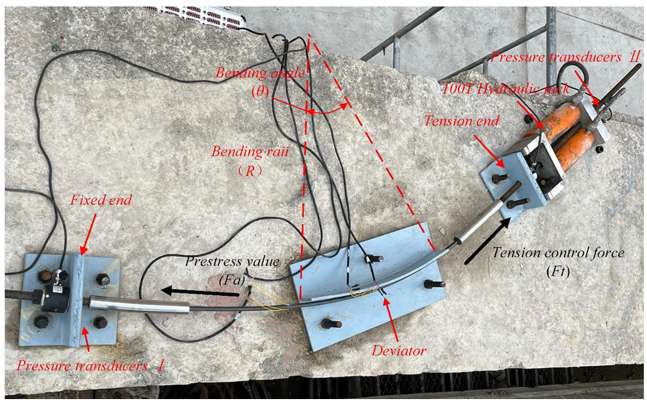
In this test, the specimens of CFRP tendons were bent once and tensioned. The test device was composed of a tensioned end, a fixed end, and a deviator, and the materials used were all Q235 steel, as shown in Figure 2. To avoid the stress concentration at the end of the deviator and the support, the centers of the supports on both sides were set at the tangential extension of the two ends of the deviator. The distance between each end of the supports on both sides and the deviator was set at 0.3 m. The CFRP reinforcement specimen was connected to the fixed support by a high-strength screw of grade 8.8, and the yield stress of the high-strength screw was 900 MPa.
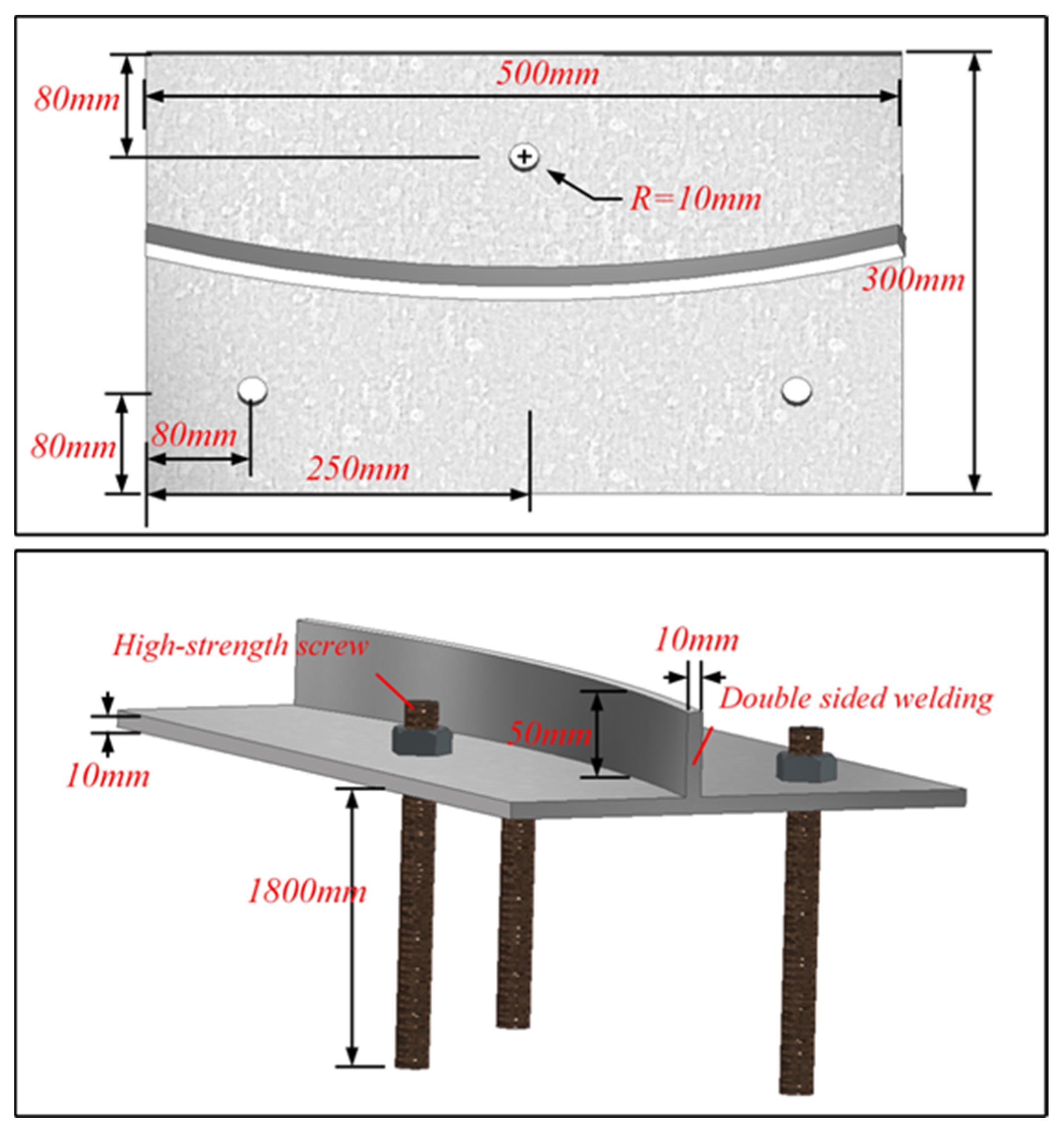
The single-bending test was intended to measure the friction loss caused by the sliding between the CFRP specimen and the deviator. Due to the material characteristics of poor shear resistance and not easy to bend, the CFRP specimen should be avoided to be subjected to excessive shear force in the test. The choice of circular deflector as the steering device of the single-bending test effectively avoids the damage of the CFRP specimen and explores the effect of different external conditions on the friction loss in a more intuitive way. The deviator was welded by an arc-shaped plate and a fixed, flat plate. The thickness of the arc-shaped plate was 10 mm. The friction coefficient of the contact surface between the deviator and the specimen was changed by applying lubricating oil (high-temperature molybdenum disulfide grease) and laying polytetrafluoroethylene (PTFE) plates. Three test conditions were set for the contact interface. From the test and evaluation of the bending tensile strength of CFRP bundles by Xia et al. [37] it is known that when the bending radius of CFRP bundles is above 1.5 m, the strength retention can reach more than 70%, which meets the test requirements. Due to the limitation of the test site, the bending angles of 20° and 30° were selected as the working conditions. The deviator was fixed in reinforced concrete by post-anchoring technology, with the specific dimensions shown in Figure 3.
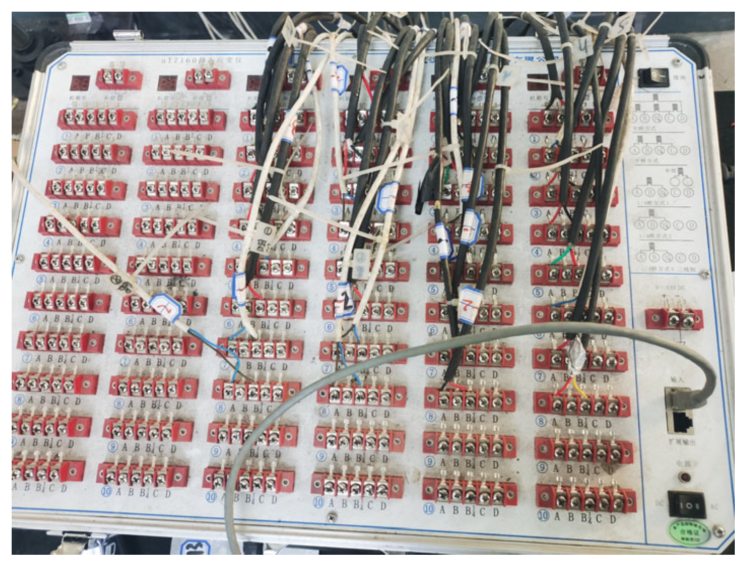
In Figure 2, force sensor I was placed at the tensioned end of the specimen to measure the tension control force, Ft; force sensor II was placed at the fixed end to measure the prestress value, Fa, subject to frictional losses, and data were collected at the frequency of 5 Hz through a dynamic strain acquisition instrument. Data acquisition instrument is was the uT7150A static strain gauge from uTeKL Company, as shown in Figure 4, with a measurement error of ±0.01%FS ± 1με.
A hydraulic jack was arranged at the tensioned end support to prestress the CFRP tendons at the loading rate of 1 kN/s. When the tension control force reached 10 kN, 20 kN, 40 kN, and 60 kN, the load was held for 10 min to observe the changes in prestressing.
There were 12 sets of working conditions in the single-bending test. The variable controlled by the test contains the friction coefficient, μ, between the CFRP tendons and the deviator, the bending radius, R, and the bending angle, θ. The specifically selected values of variables are shown in Table 2.

2.3. Three-Continuous-Bending Test

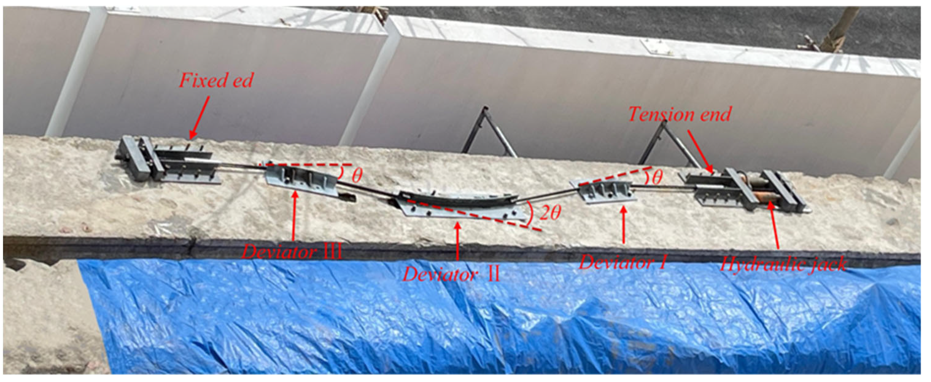
To measure the friction loss of the CFRP tendons under three-continuous-bending, as shown in Figure 5, the number of deviators was set to 3, which started from the tensioned end and were respectively denoted as deviator I, deviator II, and deviator III, and the straight-line distance between the endpoints of deviators was 0.3 m. Force sensor I and force sensor II were arranged on the supports on both sides to measure the tension control force, the prestress value, and the collection frequency was 5 Hz.
In this test, as shown in Table 2, there were four test conditions set for three-continuous-bending tests, denoted as CR-1, CR-2, CR-3, and PR-1. In the test conditions of the multiple bending tests, the friction coefficient of the contact surface was changed by laying or removing a PTFE plate, and there were two contact surface working conditions in total, CFRP-no-low carbon steel and CFRP-PTFE-low carbon steel. Due to the limitations of the test site, only two bending radii of 1.5 m and 2 m of the CFRP tendon specimens and two bending angles of 19°-38°-19° and 28°-56°-28° were tested for the three-continuous-bending test.

2.4. Friction Coefficient Determination

A total of 3 friction interface conditions were set in this test, namely CFRP-no-low carbon steel, CFRP-lubricating oil-low carbon steel, and CFRP-PTFE-low carbon steel. To facilitate the subsequent analysis of experimental results and theoretical calculation, the friction coefficient of each friction interface was measured, with the test results shown in Table 3.

3. Test Results and Analysis

3.1. Test Process

3.1.1. Single-Bending Test

When the CFRP tendon specimen was just installed, the fixed supports at both ends had a slight axial force on the CFRP tendons to keep the CFRP tendons in a bending state. The sensor data at these ends measured in the test were close, approximately 0.3 kN.
In the initial stage of prestressed loading, due to the gap between the test devices, the tension control force, Ft, increased slowly, and the prestressed value, Fa, at the fixed end remained unchanged; when Ft was greater than a certain value, Fa began to increase, and the CFRP tendon specimen adhered to the curved plate of the deviator, and the certain value was denoted as it was the initial value, Fb, measured as 4.6 kN~7.9 kN.

3.1.2. Three-Continuous-Bending Test

When the CFRP tendon specimen was installed, the sensor data at both ends were close, approximately 0.6 kN. In the three-continuous-bending test, the initial value of the tension was in the range of 9.8 kN~14.3 kN, and the deviation was relatively great among various sets of working conditions, and the values were associated with the installation accuracy.

3.2. Test Results

Data collected in the bending test of the prestressed CFRP tendons were Fa and Ft, respectively. The frictional force, f, generated by the CFRP tendon specimen and the deviator was obtained by subtraction between the two, as shown in Figure 2.
The friction loss rate under tension control forces at various levels was calculated by the following formula (Equation (1)):
η = f/Ft = (Ft − Fa)/Ft
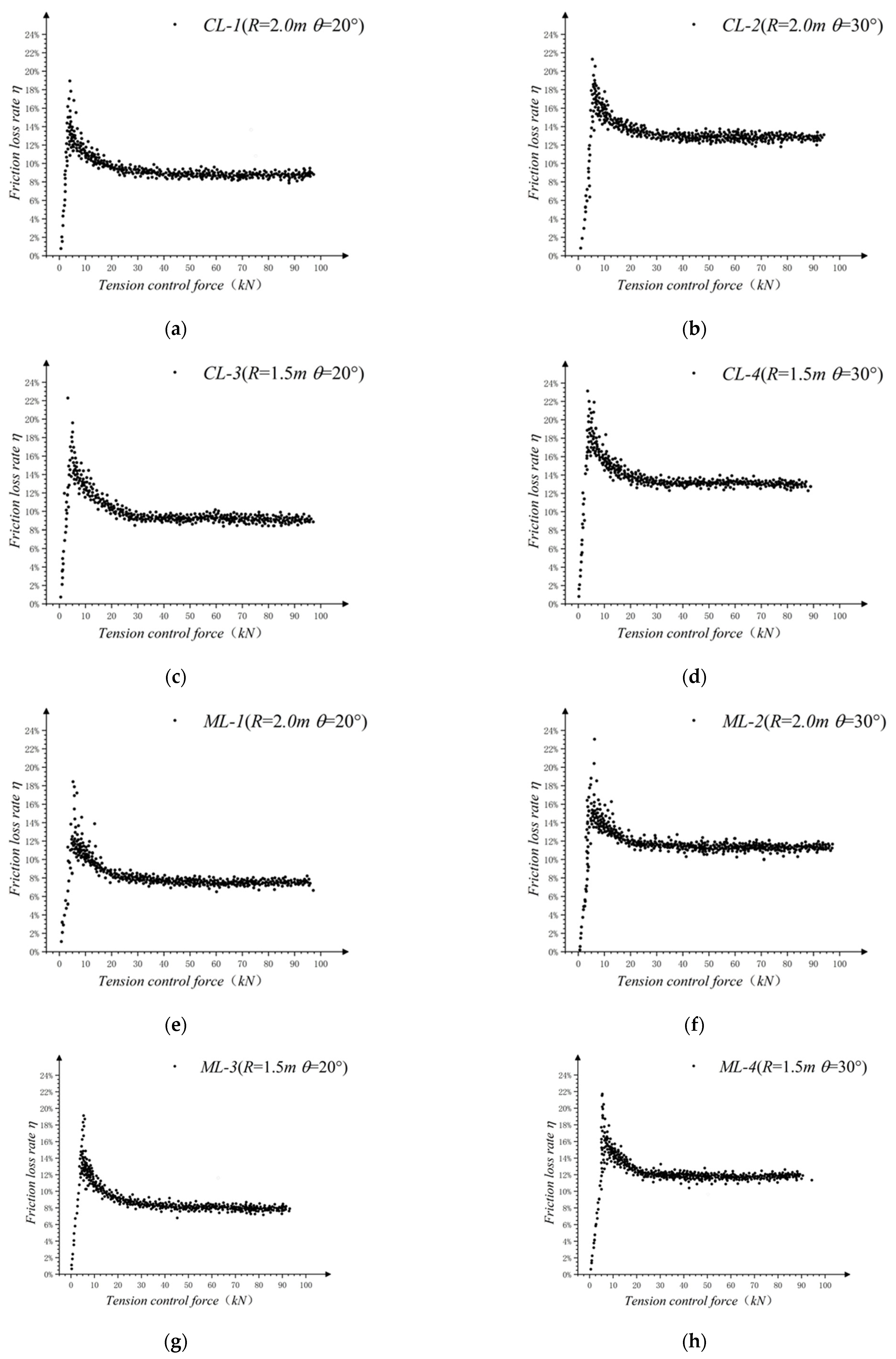
The original data obtained from each working condition were taken, and the data in the load-holding stage were excluded. The tension control force served as the x-axis, and the friction loss rate, η, served as the y, which both are shown in Figure 6.
With the scatter diagram in Figure 6, the change in the friction loss rate, η, can be divided into three stages: the increasing stage, the decreasing stage, and the stable stage.
In the growth phase, the rate of change of η was high and approximately linear. The reason for this change was that the prestress was not applied sufficiently at the beginning of loading, and the CFRP tendons only partially occur relative slip and the prestressed value, Fa, remains unchanged; in the decline phase, η gradually decreased, and the change rate decreased with the increase of the tension control force, Ft, until it tended to 0. The change law is an approximately inverse proportional curve; η stabilizes at a fixed value in the stability phase, and the fixed value is recorded as the friction loss rate stability value, ηm.
To facilitate the analysis of the internal law of the data points of the falling section and reduce the error caused by the test, the average friction loss rate under 20 kN, 40 kN, 60 kN, and 80 kN was taken for collation, as shown in Table 4. The dispersion degree of the average friction loss rate and the test data can be expressed by the average deviation, A.D. The average deviation of each group of data is in the range of 0.01–0.25, which is small, and the dispersion degree is low.

3.3. Influencing Parameter Analysis

3.3.1. Comparison of Curvature Radii, R

The magnitude of the friction loss rate and its change rate under different working conditions were significantly different. To understand the influence of each parameter on the friction loss rate, the raw data were analyzed by the control variable method.
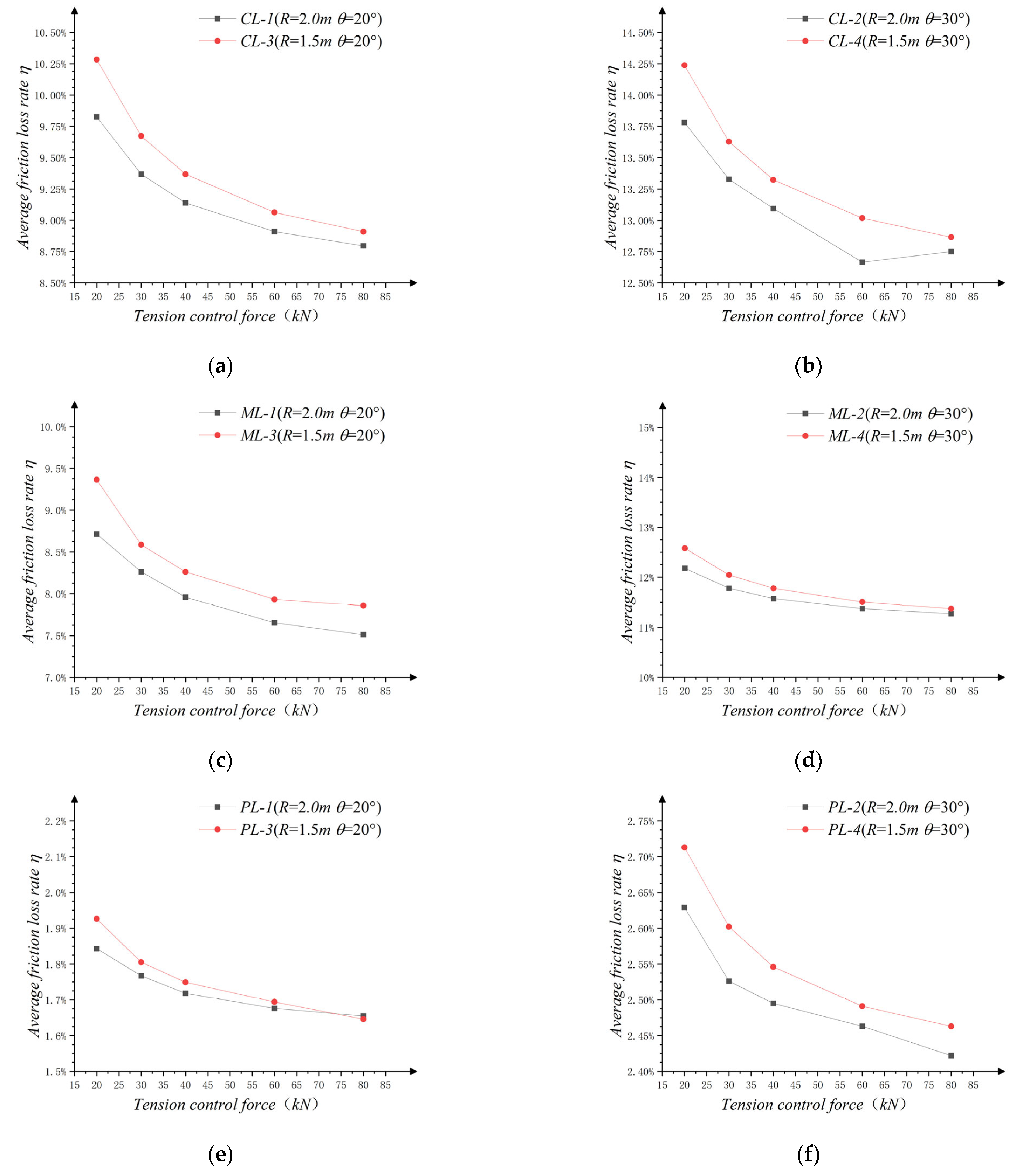
To understand the influence of R on the test results, the average friction loss rate, η, under each working condition is compared and analyzed, as shown in Figure 7.
In general, the friction loss rate decreased with an increase in the tension control force, Ft, and the change law approximated an inverse proportional function. When the friction interface was constant and the deviation angle was the same, the rate of the friction loss under the condition of the 1.5 m radius of the curvature of the deviator under the tensed control force at each level was greater than the friction loss rate under the condition of the 2.0 m radius of the curvature of the deviator. Thus, R was negatively correlated with friction loss rate. At the same time, under the different curvature radii, the decreasing rates of the friction loss were also slightly different.
When Ft was smaller than 35 kN, R had a significant correlation. With an increase in Ft, the effect of R on η gradually decreased.

3.3.2. Comparison of the Deviation Angles, θ

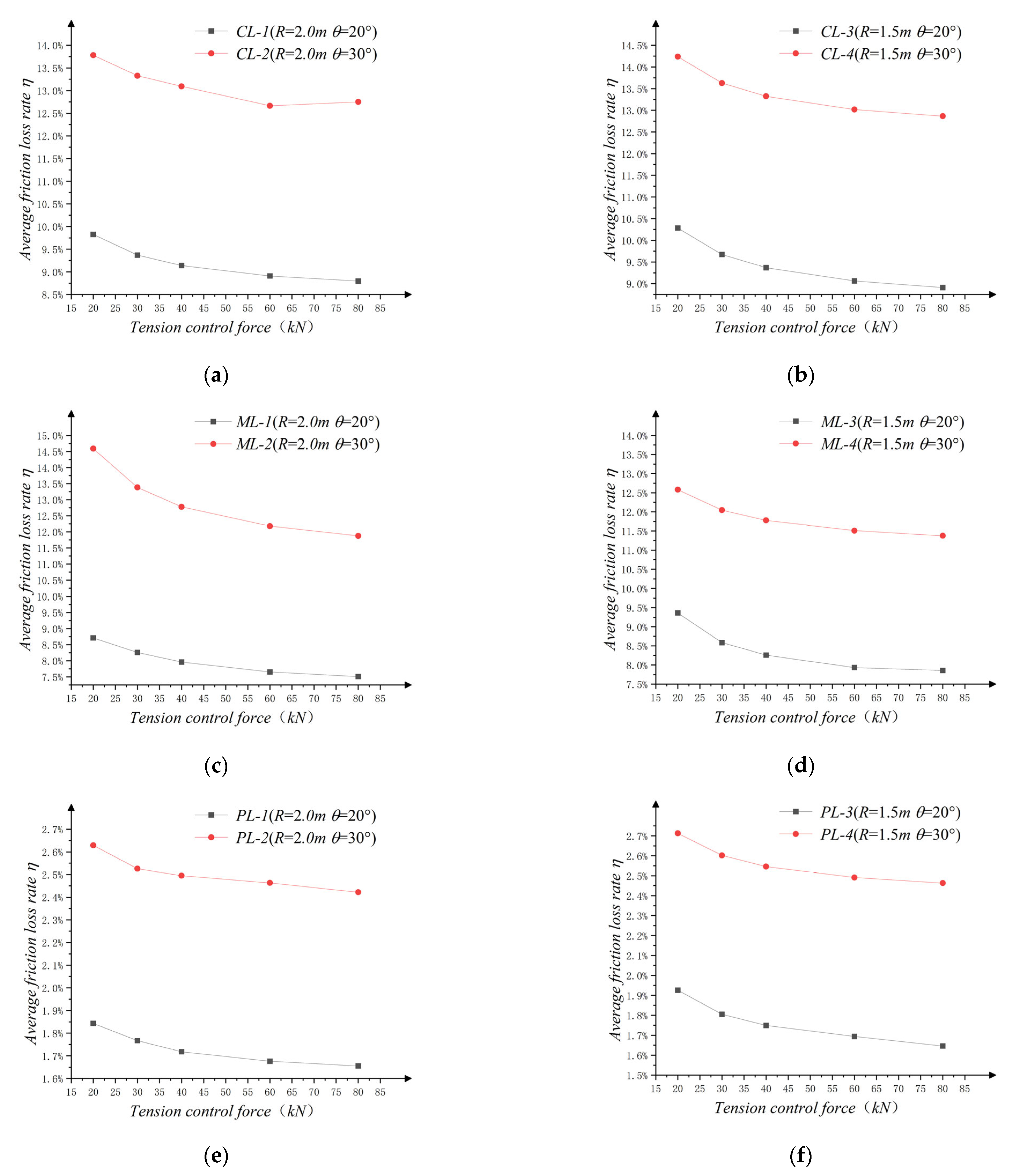
Compared with the effects of R on η, the effects of θ were more significant. By controlling the variables except θ, the test data obtained from a single-bending test are collated, and they are compared in groups, as shown in Figure 8.
As seen from Figure 8, θ is positively correlated with η with same Ft. At the same time, the values of loss rate differences between the two working conditions, Δη, remain at the same levels under each level of Ft. The average values of these loss rate differences of all groups were 3.616%, 3.517%, 3.8128%, 3.9148%, 0.7752%, and 0.799%.

3.3.3. Comparison of the Friction Coefficient, μ

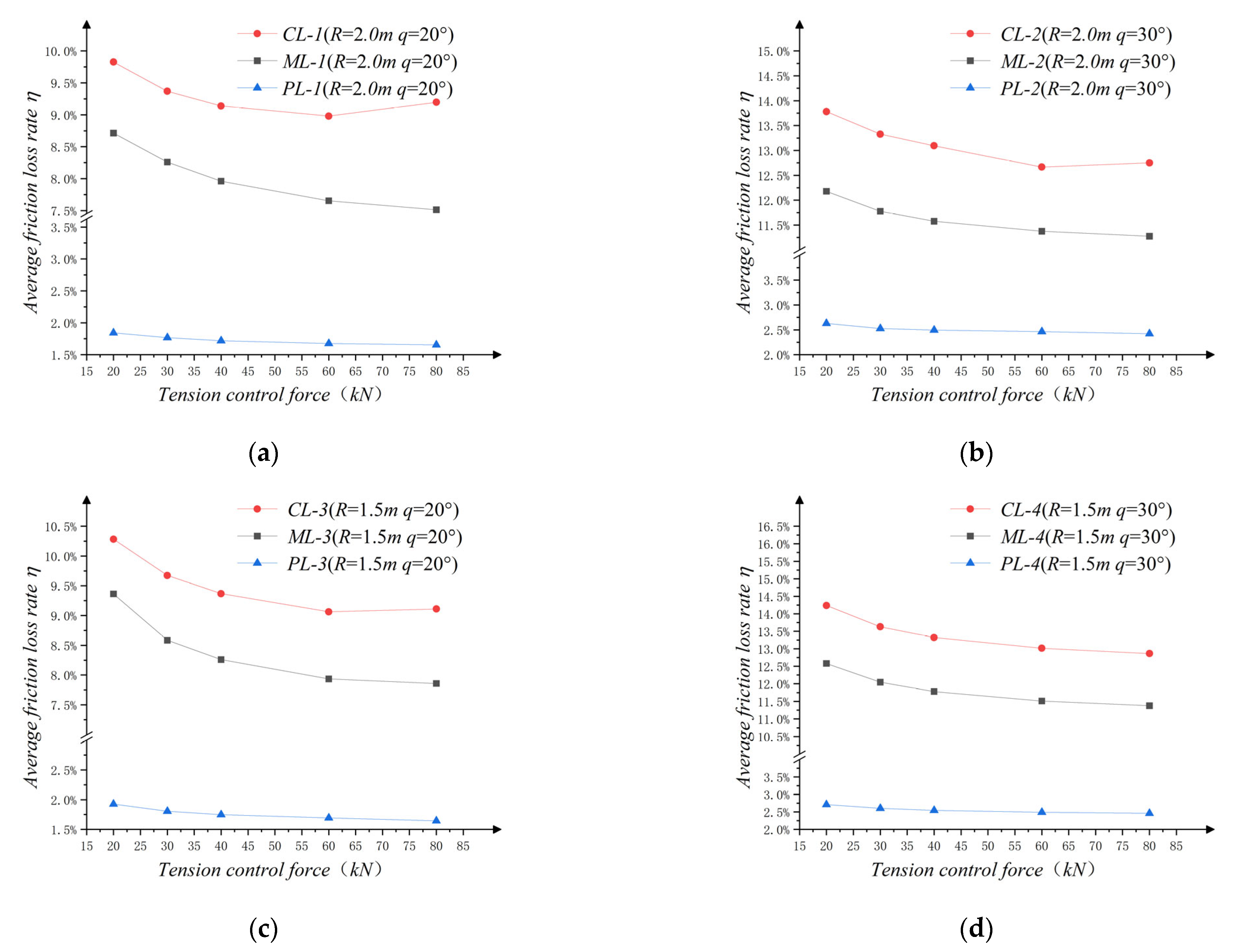
Figure 9 shows the comparison of η under different contact interfaces. Under variously tensioned control forces, a greater friction coefficient resulted in a higher loss rate.
The friction loss rates of CL-1 and ML-1, CL-2 and ML-2, CL-3 and ML-3, and CL-4 and ML-4 were counted, and it was found that the average values of the loss rate differences of all groups were discrete at fixed values, which were 1.179%, 1.502%, 1.108%, and 1.546%, respectively. Among them, the friction loss rate differences between ML-2 and CL-2, ML-4 and CL-4 are close to and generally larger than that of the other two groups. That is, relative to R, θ has a greater impact on Δη.

3.3.4. Comparison under Multiple Bending

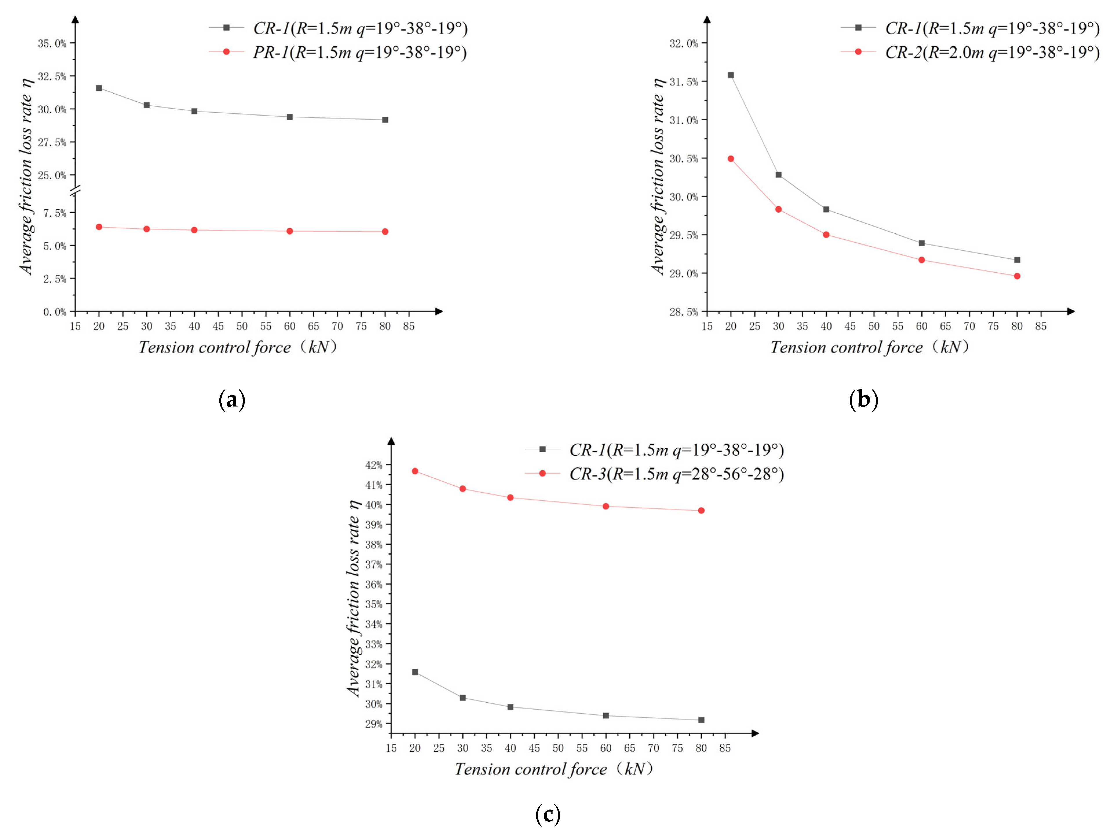
To further understand the variation law of the interface friction loss produced by the CFRP tendons and the deviator, the number of the bending times of the CFRP tendons was increased, changing from single-bending to three-continuous-bending. The test data of multiple bending under different conditions were compared, as shown in Figure 10.
The variation law of the interfacial friction loss of CFRP tendons under three-continuous-bending was similar to that of single-bending. That is to say, μ and R affected the decreased rate and decreased magnitude of η; μ and θ affected the size of the stable value, ηm, of the friction loss rate. It can be concluded, then, that the behavior of the three-continuous-bending of the CFRP tendons can be considered in a manner similar to those of continuous single-bending.

4. Calculation Method of the Friction Loss of the Prestressed CFRP

4.1. Friction Loss Calculation during Installation Stage

In the installation stage, the prestress of the tensioned end had not yet been applied, and the internal tension of the CFRP tendons was neglected. As shown in Figure 11, the internal tension can be divided into two parts according to the curvature of the test specimen: the curvature gradient segment, whose curvature changes uniformly along the length of the specimen, can be approximated as a straight-line segment for calculation, and the lengths are La and Lt respectively; the curvature fixed segment with constant curvature size, with size maintained at 1/R. According to the change in the external forces, Pa and Pt, applied on the specimen, the concentrated force was exerted by the support, which was perpendicular to the specimen, and the concentrated forces, Par and Ptr, applied by the deviator along the radial direction, respectively. The positions of action are at both ends of the deviator.
During the single-bending test, the curvature gradient segment was considered a straight-line segment, so the approximate value of the concentrated force, Pi, could be obtained as follows (Equation (2)):
P ≈ EI/LR
In other words, the concentrated radial force exerted by the deviator on the CFRP tendons in the single-bending test can be obtained as follows (Equation (3)):
Pi = Par + Ptr(EI/R)(1/La + 1/Lt)
where, Pi—the numerical sum of the concentrated forces of the CFRP tendons in the deviator.
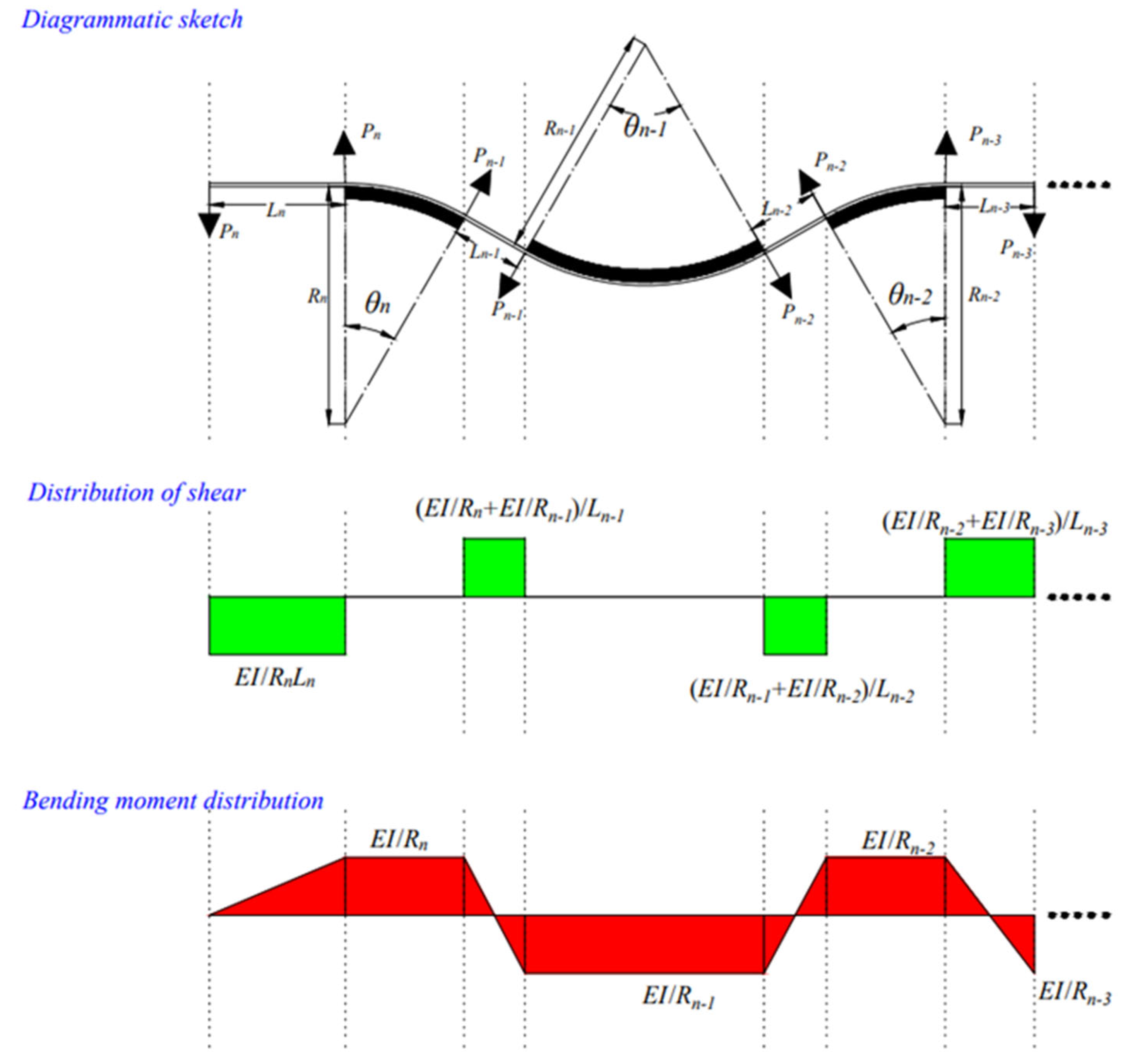
In the multiple-continuous-bending model, the number of deviators was increased from 1 to n, and the calculation formula of the concentrated radial force was also needed to consider the increase of the concentrated force caused by multiple bending, as shown in Figure 12.
To facilitate the calculation and application in engineering practice, the curvature gradient segment of the CFRP tendon specimen was approximated as a straight-line segment, and the action point of the shear force was close to the endpoint of the deviator. For the curvature fixed segment of CFRP tendons fitted to the deviator, the change in curvature of the curvature gradient segment is the sum of the absolute values of the curvature on both sides (Equations (4) and (5)):
P(n−1) ∙ L(n−1) = EI (1/Rn + 1/R(n−1))
P i = P 0 + 2 ( P 2 + P 3 P ( n - 2 ) + P ( n - 1 ) ) + P n = E I · ( 1 / ( R 1 · L a ) + 1 / ( R n · L t ) ) + E I · ( i = 1 ) ( n - 1 ) ( 2 / ( R i · L i ) + 2 ( / R ( i + 1 ) · L i ) )
where L(n−1)—distance between the deviator N and the deviator n−1; P0, Pn, represent the concentrated force exerted by the tension end and the fixed end, respectively.
Therefore, the friction loss rate caused by the installation stage is (Equation (6)):
ηi =μ Pi/Ft

4.2. Friction Loss Calculation during the Tensioned Stage

Under the action of the CFRP axial force, the deviator produced a compressive stress perpendicular to the neutral axis of the CFRP tendon, which resulted in a frictional force, f, opposite to its tension direction, which led to the friction loss of the prestressed CFRP tendons. The differential equations are used to establish the theory of calculating friction loss regarding Fa, μ, and θ.
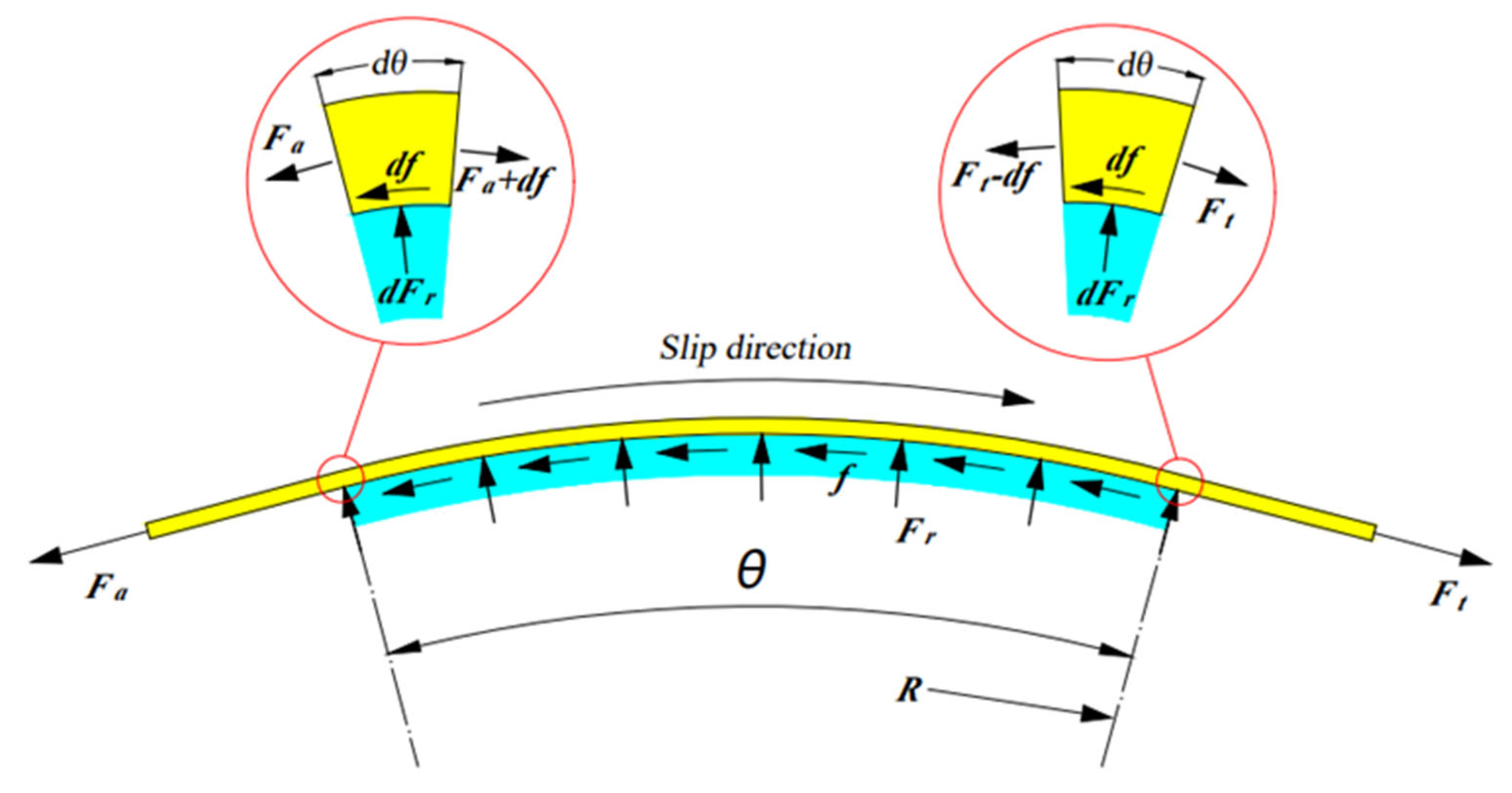
As shown in Figure 13, the curvature fixed segment of the CFRP tendons was taken for the force analysis. As shown, the prestressed CFRP tendon was subjected to compressive stress, Fr, in the radial direction, and two axial forces, Fa and Ft, where Fa is the tension control force exerted by the tensioned-end jack, and Ft is the axial force held on the CFRP tendon after friction loss, and its value is the tension control force minus the friction force (f), i.e., F = Faf.
The prestressed CFRP tendons were differentiated and divided into countless equal arcs according to the angle of the arc occupied, the angle occupied by each equal arc was , and the friction force generated by the arc was df.
The differential equation was established according to the force balance relationship and is as follows (Equations (7)–(9)):
F∙cos (1/2) dθ = (F−df) ∙cos (1/2) dθ + df
F⋅sin (1/2) dθ + (F−df)∙sin (1⁄2) dθ = dFr
df =μ dFr
df is a very small quantity compared with the other two terms and was ignored here. Based on that, by combining Equation (7) and Equation (8), the following equation was obtained (Equation (10)):
(Ft−f) ∙sin (1⁄2) dθ = df
By integrating along the bending section of the CFRP tendons, we can get the friction loss formula (Equation (11)):
fs = (1 − e−μθ) ∙Ft
The formula of the friction loss rate under the tension stage under single-bending conditions is as follows (Equation (12)):
ηs = fs/Ft = 1 − e−μθ
The formula of the friction loss rate under the tension stage under multiple bending condition is as follows (Equation (13)):
η s = f s / F t = 1 e ^   ( 1 n μ i θ i )

4.3. Theoretical Verification

The compressive stress between the specimen and the deviator was regarded as the result of the superposition of the concentrated force generated in the installation stage and the compressive stress generated in the tension stage. Therefore, the calculation of the total friction loss rate η was divided into two parts (Equation (14)):
η = ηi + ηs
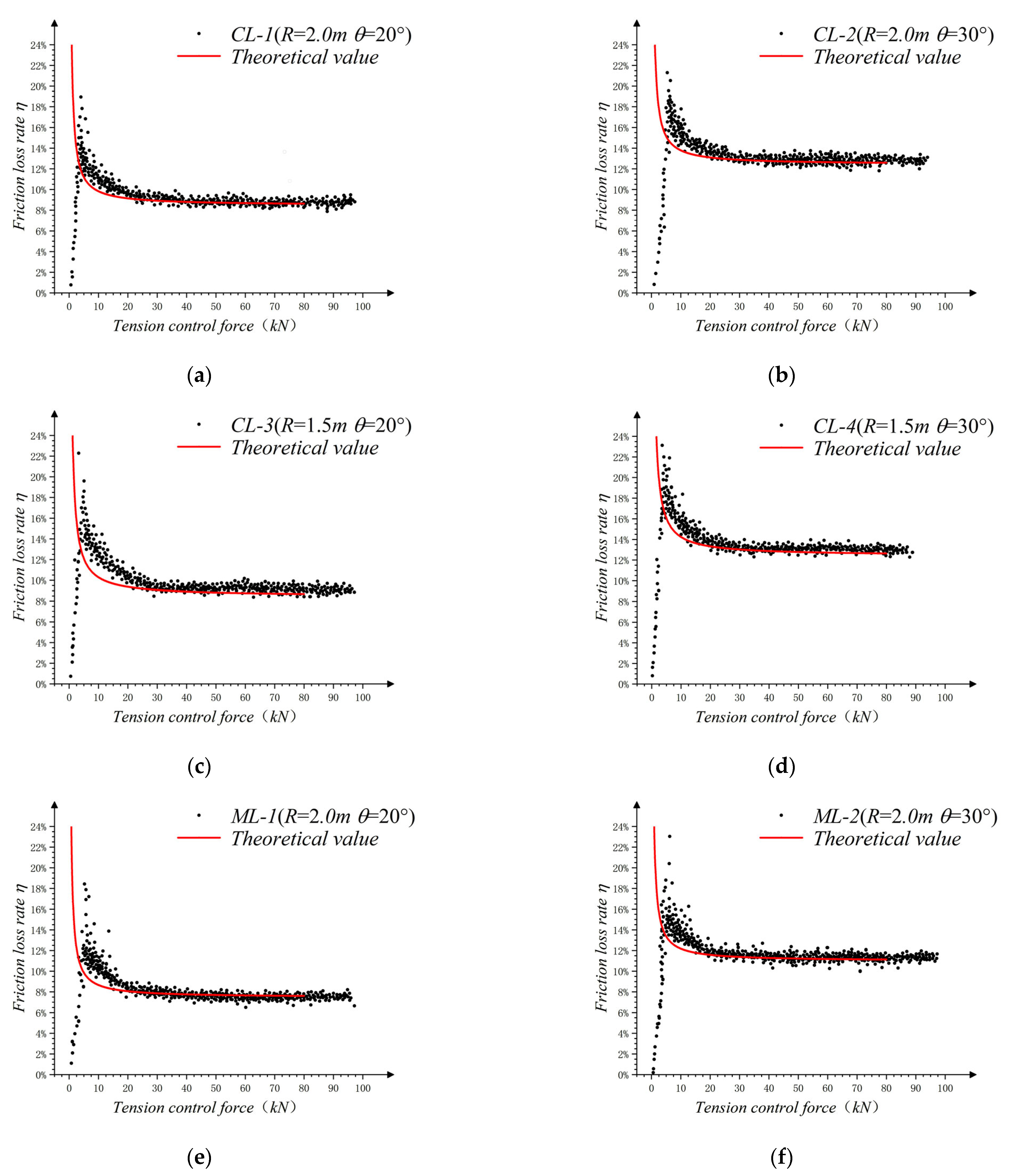
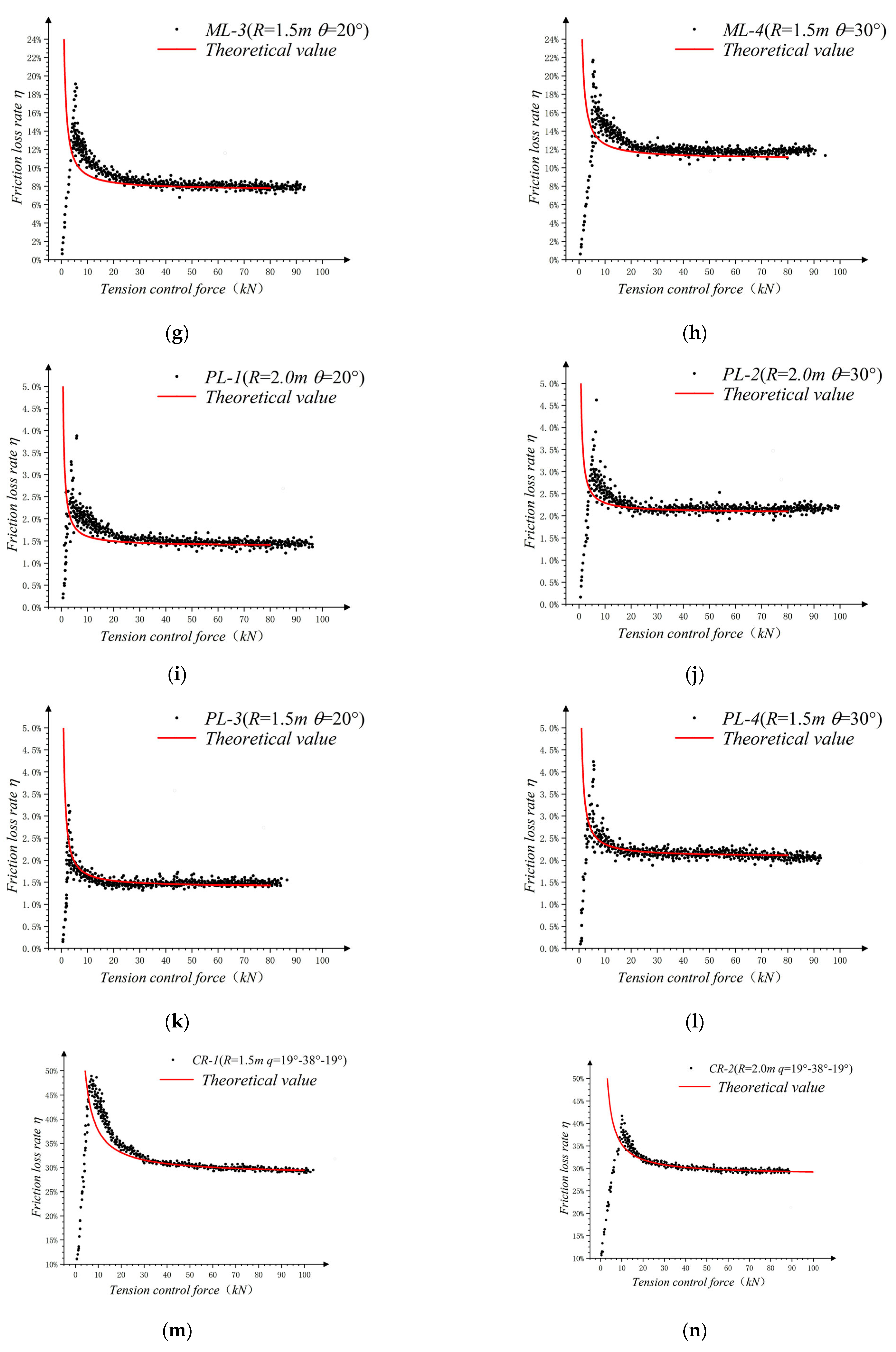
Formula (14) was substituted into each working condition for calculating its theoretical value, and the value was compared with the experimental data, as shown in Figure 14.
In general, the theoretical and experimental values of the friction loss rate are consistent with each other. The theoretical value of the friction loss rate is smaller than the experimental value, and the deviation between the two decreased with an increase in the tension-control force. Compared with the single-bending test, the initial theoretical deviation of the three-consecutive-bending tests was greater. In the theoretical verification of the three-consecutive-bending tests, the relative theoretical deviation of the PR-1 group was relatively greater, and the theoretical value deviates from the experimental value by approximately 0.5% to 1.5%. Based on the summary of the tests and theoretical analysis, the reason for this error is that there was large friction at the contact between the connecting screws and the supports between the CFRP tendons and the supports at both the ends. However, this influencing factor was not considered in the calculation theory, which made the friction force generated during the installation stage larger than the theoretical value. When the tension control force increased, the effects of the errors on the theoretical results reduced, and the theoretical value was found to be in good agreement with the experimental results.
The existing design methods for external prestressing take steel bars or steel cables as the design object, and the related calculation methods are not very suitable for the application of CFRP materials in bending reinforcement. This study can provide data and theoretical reference for the application of CFRP materials in the field of external prestressing reinforcement.
At present, this study only analyzed the mechanism of the action of friction loss during bending reinforcement of CFRP specimens with a diameter of 10 mm. At the same time, the theory neglected the friction loss generated by the CFRP specimen at the support and the segmental slip of the CFRP specimen during the tensioning process. In subsequent studies, more numerical simulation work will be added to simulate the whole tensioning process.

5. Conclusions

In this study, a prestressing tension test of CFRP tendons was designed to measure the friction loss under different bending conditions. Relating the experimental phenomena to the data variations and verifying them by the theory of friction loss rate calculation, the following conclusions can be drawn:
  • The instantaneous friction loss of the external prestressed CFRP tendons was generated under the combined action of tension and bending, and its value primarily depended on the bending radius, the deviation angle, the friction coefficient, and the tension prestress.
  • The changes in friction loss rate can be divided into three stages: a linear growth stage caused by the insufficient slip of the CFRP tendons; a decreasing stage where the friction loss rate generated in the installation stage gradually decreases with an increase in the tension control force; and the stable stage where the friction loss rate in the installation stage was negligible, and the total friction loss rate is basically unchanged in the tension stage.
  • The friction loss rate of the prestressed CFRP tendons can be simplified by superimposing the friction loss rate of several successive bends in the friction loss rate calculation model.
  • The proposed model considers the factors such as friction coefficient, bending condition, and prestress value, and the calculated value is in good agreement with the test value, which can be used to calculate the friction loss rate of prestressed CFRP tendons under different bending conditions.

Author Contributions

Conceptualization, J.F.; methodology, J.F.; software, J.F.; validation, J.F., T.Z. and B.W.; formal analysis, J.F.; investigation, J.F. and T.Z.; resources, J.F. and T.Z.; data curation, J.F.; writing—original draft preparation, J.F.; writing—review and editing, J.F. and B.W.; visualization, J.F. and B.W.; supervision, P.Z.; project administration, J.F., J.X. and W.C.; funding acquisition, P.Z. All authors have read and agreed to the published version of the manuscript.

Funding

This research was funded by the National Natural Science Foundation of China (grant No. 52078256), Zhejiang province public welfare projects (Grant No. LGF22E080023), and Zhejiang Provincial Natural Science Foundation (Grant No. LHY21E090002).

Data Availability Statement

Not applicable.

Conflicts of Interest

The authors declare that they have no known competing financial interests or personal relationships that could have appeared to influence the work reported in this paper.

References

  1. Noble, D.; Nogal, M.; O׳connor, A.; Pakrashi, V. The effect of prestress force magnitude and eccentricity on the natural bending frequencies of uncracked prestressed concrete beams. J. Sound Vib. 2016, 365, 22–44. [Google Scholar] [CrossRef] [Green Version]
  2. Bonopera, M.; Chang, K.C.; Chen, C.C.; Sung, Y.C.; Tullini, N. Prestress force effect on fundamental frequency and deflection shape of PCI beams. Struct. Eng. Mech. 2018, 67, 255–265. [Google Scholar] [CrossRef]
  3. Pimenta, S.; Pinho, S.T. Recycling carbon fibre reinforced polymers for structural applications: Technology review and market outlook. Waste Manag. 2011, 31, 378–392. [Google Scholar] [CrossRef] [PubMed] [Green Version]
  4. Karataş, M.A.; Gökkaya, H. A review on machinability of carbon fiber reinforced polymer (CFRP) and glass fiber reinforced polymer (GFRP) composite materials. Def. Technol. 2018, 14, 318–326. [Google Scholar] [CrossRef]
  5. Bakis, C.E.; Bank, L.C.; Brown, V.L.; Cosenza, E.; Davalos, J.F.; Lesko, J.J.; Machida, A.; Rizkalla, S.H.; Triantafillou, T.C. Fiber-Reinforced Polymer Composites for Construction—State-of-the-Art Review. J. Compos. Constr. 2002, 6, 73–87. [Google Scholar] [CrossRef] [Green Version]
  6. Yu, K.; Shi, Q.; Dunn, M.L.; Wang, T.; Qi, H.J. Carbon Fiber Reinforced Thermoset Composite with Near 100% Recyclability. Adv. Funct. Mater. 2016, 26, 6098–6106. [Google Scholar] [CrossRef]
  7. Zang, M.; Hu, Y.; Zhang, J.; Ye, W.; Zhao, M. Crashworthiness of CFRP/aluminum alloy hybrid tubes under quasi-static axial crushing. J. Mater. Res. Technol. 2020, 9, 7740–7753. [Google Scholar] [CrossRef]
  8. Tang, E.; Li, W.; Han, Y. Research on the interacting duration and microscopic characteristics created by high-velocity impact on CFRP/Al HC SP structure. J. Mater. Res. Technol. 2020, 9, 1640–1651. [Google Scholar] [CrossRef]
  9. Al-Rousan, R.; Al-Tahat, M. An Anchoring Groove Technique to Enhance the Bond Behavior between Heat-Damaged Concrete and CFRP Composites. Buildings 2020, 10, 232. [Google Scholar] [CrossRef]
  10. Kim, T.-K.; Park, J.-S.; Kim, S.-H.; Jung, W.-T. Structural Behavior Evaluation of Reinforced Concrete Using the Fiber-Reinforced Polymer Strengthening Method. Polymers 2021, 13, 780. [Google Scholar] [CrossRef]
  11. Borri, A.; Corradi, M.; Grazini, A. A method for flexural reinforcement of old wood beams with CFRP materials. Compos. Part B Eng. 2005, 36, 143–153. [Google Scholar] [CrossRef]
  12. El-Hacha, R.; Soudki, K. Prestressed near-surface mounted fibre reinforced polymer reinforcement for concrete structures—A review. Can. J. Civ. Eng. 2013, 40, 1127–1139. [Google Scholar] [CrossRef]
  13. Wang, X.; Shi, J.; Wu, G.; Yang, L.; Wu, Z. Effectiveness of basalt FRP tendons for strengthening of RC beams through the external prestressing technique. Eng. Struct. 2015, 101, 34–44. [Google Scholar] [CrossRef]
  14. Wight, R.; El-Hacha, R.; Erki, M. Prestressed and non-prestressed CFRP sheet strengthening: Damaged continuous reinforced concrete beams. Int. J. Mater. Prod. Technol. 2003, 19, 96. [Google Scholar] [CrossRef]
  15. Al-Rousan, R.; Nusier, O.; Abdalla, K.; Alhassan, M.; Lagaros, N.D. NLFEA of Sulfate-Damaged Circular CFT Steel Columns Confined with CFRP Composites and Subjected to Axial and Cyclic Lateral Loads. Buildings 2022, 12, 296. [Google Scholar] [CrossRef]
  16. Täljsten, B.; Hansen, C.S.; Schmidt, J.W. Strengthening of old metallic structures in fatigue with prestressed and non-prestressed CFRP laminates. Constr. Build. Mater. 2009, 23, 1665–1677. [Google Scholar] [CrossRef]
  17. Aslam, M.; Shafigh, P.; Jumaat, M.Z.; Shah, S.N.R. Strengthening of RC beams using prestressed fiber reinforced polymers—A review. Constr. Build. Mater. 2015, 82, 235–256. [Google Scholar] [CrossRef]
  18. Yang, D.-S.; Park, S.-K.; Neale, K.W. Flexural behaviour of reinforced concrete beams strengthened with prestressed carbon composites. Compos. Struct. 2009, 88, 497–508. [Google Scholar] [CrossRef]
  19. Wang, W.-W.; Dai, J.-G.; Harries, K.A.; Bao, Q.-H. Prestress Losses and Flexural Behavior of Reinforced Concrete Beams Strengthened with Posttensioned CFRP Sheets. J. Compos. Constr. 2012, 16, 207–216. [Google Scholar] [CrossRef]
  20. Jia, L.; Fang, Z.; Hu, R.; Pilakoutas, K.; Huang, Z. Fatigue Behavior of UHPC Beams Prestressed with External CFRP Tendons. J. Compos. Constr. 2022, 26, 04022066. [Google Scholar] [CrossRef]
  21. Ng, S.T.K.; Soudki, K. Shear Behavior of Externally Prestressed Beams with Carbon Fiber-Reinforced Polymer Tendons. ACI Struct. J. 2010, 107, 443–450. [Google Scholar] [CrossRef]
  22. Le, T.D.; Pham, T.M.; Hao, H.; Li, H. Behavior of Precast Segmental Concrete Beams Prestressed with External Steel and CFRP Tendons. J. Compos. Constr. 2020, 24, 04020053. [Google Scholar] [CrossRef]
  23. Li, X.; Zhang, J.; Cheng, J. Study on the stiffness degradation in concrete continuous beam with externally prestressed CFRP tendons under fatigue loading. Adv. Struct. Eng. 2021, 24, 2119–2130. [Google Scholar] [CrossRef]
  24. Lou, T.; Lopes, S.M.; Lopes, A.V. Numerical analysis of behaviour of concrete beams with external FRP tendons. Constr. Build. Mater. 2012, 35, 970–978. [Google Scholar] [CrossRef]
  25. Aksoylu, C.; Özkılıç, Y.O.; Madenci, E.; Safonov, A. Compressive Behavior of Pultruded GFRP Boxes with Concentric Openings Strengthened by Different Composite Wrappings. Polymers 2022, 14, 4095. [Google Scholar] [CrossRef] [PubMed]
  26. Madenci, E.; Özkılıç, Y.O.; Aksoylu, C.; Safonov, A. The Effects of Eccentric Web Openings on the Compressive Performance of Pultruded GFRP Boxes Wrapped with GFRP and CFRP Sheets. Polymers 2022, 14, 4567. [Google Scholar] [CrossRef]
  27. Preciado, A.; Sperbeck, S.T.; Ramírez-Gaytán, A. Seismic vulnerability enhancement of medieval and masonry bell towers externally prestressed with unbonded smart tendons. Eng. Struct. 2016, 122, 50–61. [Google Scholar] [CrossRef]
  28. Sun, B. A Survey on Structural Techniques and Applications of External Prestressing. J. Southeast Univ. 2001, 31, 109–113. [Google Scholar]
  29. Rabbat, B.G.; Sowlat, K. Testing of Segmental Concrete Girders with External Tendons. PCI J. 1987, 32, 86–107. [Google Scholar] [CrossRef]
  30. Ganesh, P.; Murthy, A.R. Repair, retrofitting and rehabilitation techniques for strengthening of reinforced concrete beams—A review. Adv. Concr. Constr. 2019, 8, 101–117. [Google Scholar] [CrossRef]
  31. Grace, N.F.; Abdei-Sayed, G. Behavior of Externally Draped CFRP Tendons in Prestressed Concrete Bridges. PCI J. 1998, 43, 88–101. [Google Scholar] [CrossRef]
  32. Zhao, L.; Dou, T.; Cheng, B.; Xia, S.; Yang, J.; Zhang, Q.; Li, M.; Li, X. Theoretical Study and Application of the Reinforcement of Prestressed Concrete Cylinder Pipes with External Prestressed Steel Strands. Appl. Sci. 2019, 9, 5532. [Google Scholar] [CrossRef] [Green Version]
  33. Zhou, Z.; He, J.; Chen, G.; Ou, J. A Smart Steel Strand for the Evaluation of Prestress Loss Distribution in Post-tensioned Concrete Structures. J. Intell. Mater. Syst. Struct. 2009, 20, 1901–1912. [Google Scholar] [CrossRef]
  34. Yuan, H.; Li, Y.; Zhou, B.; He, S.; Wang, P. Friction Characteristics of Post-Tensioned Tendons of Full-Scale Structures Based on Site Tests. Adv. Civ. Eng. 2020, 2020, 5916738. [Google Scholar] [CrossRef]
  35. Kim, S.-H.; Park, S.Y.; Park, Y.; Jeon, S.-J. Friction characteristics of post-tensioning tendons in full-scale structures. Eng. Struct. 2019, 183, 389–397. [Google Scholar] [CrossRef]
  36. Fang, Y.; Fang, Z.; Jiang, Z.; Jiang, R.; Zhou, X. Investigation on failure behavior of carbon fiber reinforced polymer wire subjected to combined tension and bending. Compos. Struct. 2021, 267, 113927. [Google Scholar] [CrossRef]
  37. Xia, J.; Xu, Z.; Zhuge, P.; Wang, B.; Cai, W.; Fu, J. Testing and Evaluation of Flexural Tensile Strength of Prestressed CFRP Cables. Materials 2022, 15, 7065. [Google Scholar] [CrossRef]
Figure 1. The test specimen.
Buildings 13 00099 g001
Figure 2. Arrangement diagram of the test device for the single-bending test.
Buildings 13 00099 g002
Figure 3. Dimensional drawing of the deviator.
Buildings 13 00099 g003
Figure 4. The uT7150A static strain gauge.
Buildings 13 00099 g004
Figure 5. Arrangement diagram of the three-continuous-bending test device.
Buildings 13 00099 g005
Figure 6. Scatter plot of friction loss rate: (a) CL-1; (b) CL-2; (c) CL-3; (d) CL-4; (e) ML-1; (f) ML-2; (g) ML-3; (h) ML-4; (i) PL-1; (j) PL-2; (k) PL-3; (l) PL-4; (m) CR-1; (n) CR-2; (o) CR-3; (p) PR-1.
Buildings 13 00099 g006aBuildings 13 00099 g006b
Figure 7. Comparison of data with different radius of curvature R only: (a) comparison group of CL-1 and CL-3; (b) comparison group of CL-2 and CL-4; (c) comparison group of ML-1 and ML-3; (d) comparison group of ML-2 and ML-4; (e) comparison group of PL-1 and PL-3; (f) comparison group of PL-2 and PL-4.
Buildings 13 00099 g007
Figure 8. Comparison of data with different steering radius θ only:(a) comparison group of CL-1 and CL-2; (b) comparison group of CL-3 and CL-4; (c) comparison group of ML-1 and ML-2; (d) comparison group of ML-3 and ML-4; (e) comparison group of PL-1 and PL-2; (f) comparison group of PL-3 and PL-4.
Buildings 13 00099 g008
Figure 9. Comparison of data with different friction coefficients μ only: (a) comparison group of CL-1, ML-1, and PL-1; (b) comparison group of CL-2, ML-2, and PL-2; (c) comparison group of CL-3, ML-3, and PL-3; (d) comparison group of CL-4, ML-4, and PL-4.
Buildings 13 00099 g009
Figure 10. Comparison of data from three-continuous-bending tests: (a) comparison group of CR-1 and PR-1(different μ only); (b) comparison group of CR-1 and CR-2 (different R only); (c) comparison group of CR-1 and CR-3 (different θ only).
Buildings 13 00099 g010
Figure 11. Sketch of the one bending calculation.
Buildings 13 00099 g011
Figure 12. Sketch of the continuous bending calculation.
Buildings 13 00099 g012
Figure 13. Sketch of model calculation for the tensioning stage.
Buildings 13 00099 g013
Figure 14. Comparison of theoretical value and test value: (a) CL-1; (b) CL-2; (c) CL-3; (d) CL-4; (e) ML-1; (f) ML-2; (g) ML-3; (h) ML-4; (i) PL-1; (j) PL-2; (k) PL-3; (l) PL-4; (m) CR-1; (n) CR-2; (o) CR-3; (p) PR-1.
Buildings 13 00099 g014aBuildings 13 00099 g014bBuildings 13 00099 g014c
Table 1. Material parameters of CFRP tendons.
MaterialDiameterSurfaceTensile Strength
(MPa)
Longitudinal Elastic Mode (GPa)Transverse Elastic Modulus (GPa)
CFRP10 mmSmooth rounding230016010.3
Table 2. The test conditions of the prestressed CFRP tendons.
Test Piece NoNumber of Bending, nBending Radius,
R/m
Bending Angle, θContact Surface Working Conditions
CL-112.020°CFRP-no-low
CL-212.030°CFRP-no-low
CL-311.520°CFRP-no-low
CL-411.530°CFRP-no-low
ML-112.020°CFRP-lubricating oil-low
ML-212.030°CFRP-lubricating oil-low
ML-311.520°CFRP-lubricating oil-low
ML-411.530°CFRP-lubricating oil-low
PL-112.020°CFRP-PTFE-low
PL-212.030°CFRP-PTFE-low
PL-311.520°CFRP-PTFE-low
PL-411.530°CFRP-PTFE-low
CR-131.519°-38°-19°CFRP-no-low
CR-232.019°-38°-19°CFRP-no-low
CR-331.528°-56°-28°CFRP-no-low
PR-131.519°-38°-19°CFRP-PTFE-low
Table 3. Friction coefficient determination working condition.
Friction InterfaceWhether the PTFE Plate Is ArrangedWhether the Lubricating Oil Is AppliedFriction Coefficient, μ
CFRP-no-lowNoNo0.253
CFRP-lubricating oil-lowNoYes0.226
CFRP-PTFE-lowYesNo0.040
Calculation formula of friction coefficient, μ = f/F; f is the interfacial friction, F is the tensile force of CFRP reinforcement sliding.
Table 4. Summary of the processed experimental data.
Test Piece NoAverage Friction Loss Rate, η, under Each Stage of Tension Control Force, FtFriction Loss Rate Stability Value, ηm
20 kN30 kN40 kN60 kN80 kN
CL-19.826%9.368%9.139%8.910%8.796%8.7%
CL-213.781%13.328%13.094%12.665%12.750%12.4%
CL-310.284%9.673%9.368%9.063%8.910%9.5%
CL-414.238%13.628%13.323%13.018%12.865%12.7%
ML-18.713%8.26%8.025%7.654%7.512%7.5%
ML-212.179%11.777%11.576%11.375%11.275%11.2%
ML-39.364%8.585%8.260%7.934%7.858%7.7%
ML-412.581%12.045%11.777%11.509%11.375%11.1%
PL-11.843 %1.767%1.718%1.676%1.655%1.5%
PL-22.629%2.526%2.495%2.463%2.422%2.3%
PL-31.926%1.805%1.749%1.694%1.646%1.4%
PL-42.713%2.602%2.546%2.491%2.463%2.4%
CR-131.58%30.28%29.83%29.39%29.17%29%
CR-230.49%29.83%29.50%29.17%28.96%28.5%
CR-341.67%40.78%40.34%39.90%39.68%39.5%
PR-16.40%6.24%6.16%6.08%6.04%6%
Disclaimer/Publisher’s Note: The statements, opinions and data contained in all publications are solely those of the individual author(s) and contributor(s) and not of MDPI and/or the editor(s). MDPI and/or the editor(s) disclaim responsibility for any injury to people or property resulting from any ideas, methods, instructions or products referred to in the content.