Abstract
This paper explores the lifting project of a steel structure corridor in the Haiyue Center, Quanzhou City, with a focus on mechanical response, safety, stability, and construction guidance under wind load conditions. The investigation attends to safety apprehensions stemming from the absence of horizontal constraints within the corridor, rendering it vulnerable to wind-induced loads. Measures are implemented to prevent collisions with nearby buildings during lifting. Stability challenges, including beam displacement and excessive stress, are examined. Anti-deformation trusses and inclined web rods are employed to ensure stability, prevent potential instabilities, and promote uniform deformation. The study also analyzes stress during asynchronous lifting. Through the enforcement of stringent parameters, where asynchronous displacement is confined to a maximum of 25 mm and asynchronous lifting load is limited to 20%, the structural integrity of the corridor is meticulously upheld. This judicious approach serves to not only avert deformation but also to forestall structural impairment. Therefore, the significance of stress distribution and deformation is emphasized when conducting the integral lifting of steel structure corridor between two super-tall buildings under wind load conditions. Simultaneously, relevant construction control measures have been devised, along with offering scientific recommendations for similar cases involving lifting construction processes under the influence of wind.
1. Introduction
The role of the steel structure corridor primarily revolves around its function as a connector between buildings [1]. Serving as a means of passage and illumination, it fulfills the dual purpose of connecting structures on both sides [2]. The establishment of a steel structure corridor is driven by two objectives. Firstly, it meets architectural requirements such as accommodating sightseeing activities, serving as a scenic corridor, or acting as a peaceful café [3]. Secondly, it aims to fulfill the aesthetic needs of the architecture by enhancing the impact of the facade and creating a more distinctive appearance [4]. The steel structure corridor not only assumes the responsibility of supporting its own weight and traffic loads [5], but also requires coordination with the primary structures on both sides to manage end deformations [6,7].
However, wind loads significantly impact the safety and stability of the installation of steel structure corridors between super-tall buildings. Due to the static and dynamic effects of wind loads, twisting, vibration, and deformation of steel structure corridors often occur during lifting and installation, leading to an increasing proportion of safety accidents. This is owing mainly to inappropriate choices made by construction personnel regarding the lifting and installation methods of steel structure corridors, inadequate emergency plans and corresponding measures for potentially unsafe construction projects, and insufficient emphasis by construction management on the stress changes of steel structure corridors under wind loads, without conducting numerical simulation research and analysis on the construction process of steel structure corridors. Therefore, selecting an appropriate steel structure corridor lifting construction method and minimizing the impact of wind loads on the deformation and collisions of super-tall steel structure corridors are essential prerequisites to ensure its safety and reliability for both daily construction and operation [8].
Numerous techniques exist for the hoisting and elevation of steel structure corridors. Among these, the segmented elevation construction technique is commonly employed, seeking to enhance safety protocols, minimize transportation expenses, and elevate hoisting efficiency during component installation. This is accomplished through the refinement of the construction site’s layout blueprint before commencement, thereby optimizing the construction process [9]; the high-altitude sliding method is an efficient and economical construction method for large-span reticulated shell structures. The basic operational process involves dividing the lifted items into several units, each of which is hoisted onto the designated sliding track of the building. The sliding operation is then carried out to the specified position. Finally, the units are assembled into a whole [10]. The cantilever installation construction technique involves gradually extending the installation components outward from the design height. The installed components act as support extensions, gradually expanding toward the periphery until all components are fully installed. Experimental research has demonstrated the sufficient stiffness of this method to meet deformation requirements during construction [11]; The onsite assembly construction method involves constructing a temporary support platform at the designed height of the steel structure. The pre-assembled components are then directly installed on the platform surface. By proposing a framework to optimize the planning of component sequence and arrangement, geometric variations of components and subsequent rework during the construction process are minimized. This helps avoid risks associated with structure lifting construction, while also shortening the construction period [12]; and the integral lifting construction method involves transporting structural components to the assembly platform for assembly. The general process of the lifting construction is as follows. Initially, the structural components are transported to the assembly platform and assembled. It should be noted that, to facilitate the installation work after lifting, the assembly platform is typically positioned directly beneath the installation location. Once the assembly is finished, the structure as a whole is lifted to the designated height using lifting equipment. Finally, the components are installed and secured. It is important to note that for ease of installation after hoisting, the assembly platform is generally positioned directly below the installation location [13,14,15,16]. Once assembly is complete, the entire structure is hoisted to the designated height using lifting equipment. Finally, the components are installed and secured. Through a comparison of finite element numerical simulation and actual construction monitoring results, the safety and applicability of lifting steel structure corridors under wind loads are ensured [17,18,19,20].
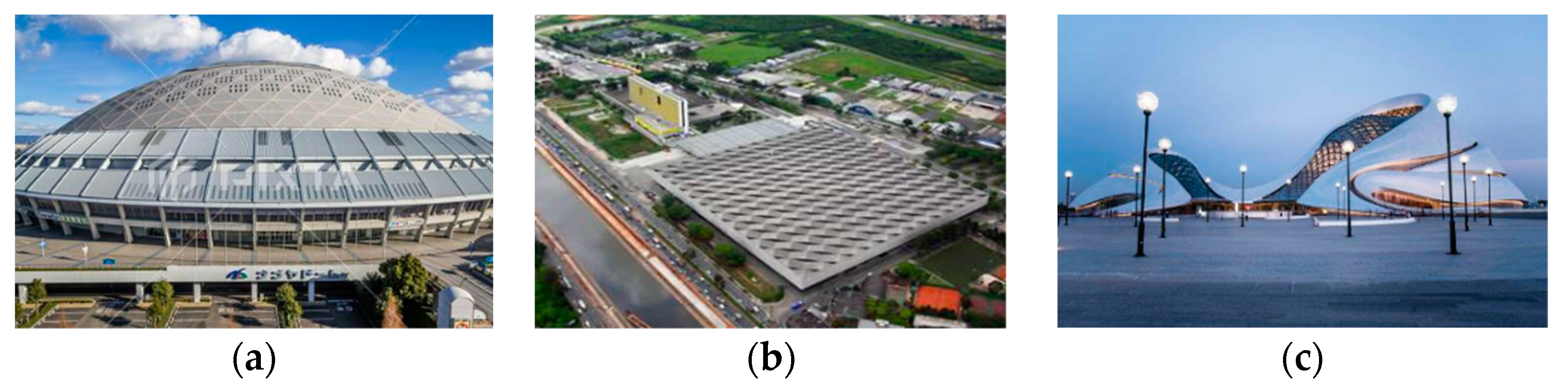
During the actual onsite construction process of steel structure corridor lifting, construction techniques such as segmented elevation, high-altitude sliding, cantilever installation, and onsite assembly involve prolonged high-altitude operations. This significantly reduces construction efficiency, increases construction process risks, and poses a safety challenge to construction personnel. Compared to other methods, the overall lifting and hoisting construction technique involves fewer high-altitude operations, and the speed and duration of hoisting can be controlled, effectively ensuring construction quality. Thus, it is widely applied in practical engineering projects. The installation and construction of the reticulated shell dome in Nagoya, Japan (Figure 1a) utilized the comprehensive hoisting and lifting method. The lifting weight exceeded 10,000 tons, and the hoisting and lifting heights approached 31 m. Similarly, the comprehensive hoisting and lifting method was employed in the installation and construction of the steel roof at the São Paulo Exhibition Center in Brazil (Figure 1b), with a lifting weight of approximately 1000 tons and a lifting height of 14 m. A representative case is the reticulated shell roof of the small theater at the Harbin Cultural Center Grand Theater, depicted in Figure 1c. The versatility of the comprehensive hoisting and lifting method is evident from the aforementioned instances. The weight and height of the lift represent maximum achievable values across all construction methods, with manageable control over construction quality and safety. Therefore, the selected construction approach involves lower platform assembly and subsequent integral lifting. This methodology significantly minimizes high-altitude operations, thereby enhancing construction efficiency and ensuring high construction quality.
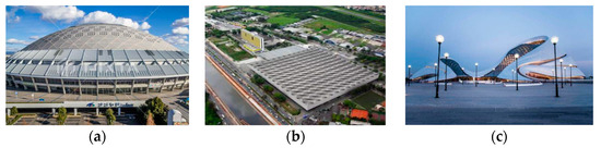
Figure 1.
Typical overall lifting structure. (a) Nagoya Netted Shell Dome in Japan. (b) São Paulo Exhibition Center in Brazil. (c) The Reticulated Roof of Harbin Cultural Center Grand Theater.
In light of the current research status both domestically and internationally, there is a need for further exploration of the safety, stability, and stress conditions of the integral hoisting and construction of steel structure corridors under wind loads. This is crucial to comprehensively guide and ensure the integral hoisting and construction process of steel structure corridors affected by wind loads [21,22,23]. This paper primarily aims to address three main challenges in this regard: (1) Ensuring the safety of the hoisting and lifting process of steel structure corridors under the influence of wind loads. (2) Resolving stability issues encountered during the hoisting and lifting process of steel structure corridors under the influence of wind loads. (3) Addressing the force-related problem of steel structure corridors when subjected to asynchronous lifting under the influence of wind loads. Therefore, this study aims to analyze the safety and stability of hoisting steel structure corridors under wind load.
To achieve this objective, this study takes the integral hoisting and construction of steel structure corridors in two super-tall buildings within the Haiyue Center project in Quanzhou City as an engineering case study. SAP2000 and ANSYS structural finite element software programs are utilized to conduct numerical simulations on the overall hoisting and lifting process of steel structure corridors under wind loads. The obtained numerical simulation results are analyzed to identify the existing problems during the hoisting process. Subsequently, corresponding measures are proposed to address these issues, and the effectiveness of these measures is verified through real-world engineering case studies in conjunction with the simulation results.
2. Methods for the Integral Lifting of Steel Structure Corridors under Wind Load
This study employs a combined approach of theoretical analysis and numerical simulation to investigate the impact of wind loads during the integral hoisting and construction process of steel structure corridors. These two distinct research methods each possess unique characteristics. By integrating and cross validating these two methods, reliable research conclusions can be obtained.
2.1. Theoretical Analysis Methodology
In the realm of studying the influence of wind loads on steel structures, both statics and aerodynamics theories remain applicable. The theoretical analysis method is based on statics and aerodynamics theories, where models and formulas fitting the actual engineering scenarios are established. Mathematical analysis methods are then applied to solve these models, ultimately providing conclusions regarding the stress, deformation, and stability of the steel structure. Theoretical analysis serves as the foundation for other research methods and plays an irreplaceable role.
2.2. Numerical Simulation and Computation
Numerical simulation and computation are based on fundamental principles related to statics and fluid mechanics. They simulate the impact of wind loads on steel structure corridors during the lifting and hoisting process, ultimately yielding calculations for internal forces and displacements of the steel structure corridor. The numerical simulation and computation method simplify the complexity associated with theoretical research. With the continuous advancement of computer technology, the precision and reliability of numerical simulation software have significantly improved. Consequently, this method is widely applied in research under various complex conditions.
Numerical simulation analysis methods primarily encompass three approaches: the time-dependent element method, the topological element method, and the finite element method. Currently, various software options are available for conducting numerical simulations, such as SAP2000, ANSYS, MIDAS, ETABS, and others, and each type of software is suitable for specific engineering conditions and materials. SAP2000 (Structure Analysis Program 2000) is a type of finite element analysis software that not only offers targeted analysis methods for various construction models but also integrates different types of analysis methods, allowing for simultaneous analysis and result output. As a result, it finds extensive applications in the field of structural engineering finite element analysis.
SAP2000 encompasses a comprehensive range of structural analysis methods, including the latest linear, nonlinear, dynamic, and static analysis methods. Its analysis capabilities primarily include static analysis, dynamic analysis, time history analysis, staged construction analysis, static-elastic-plastic analysis, and modal analysis using characteristic vectors. These capabilities are employed to address the gravity second-order effects encountered during numerical simulation research. Specifically, when the lateral stiffness of a structure or component is relatively low, it can experience lateral displacement under horizontal loading. Under vertical loading, this lateral displacement further increases, resulting in additional internal forces within the structure and potentially leading to premature instability phenomena.
3. Finite Element Analysis for the Case Study of Steel Structure Corridors under Wind Load
3.1. Project Background
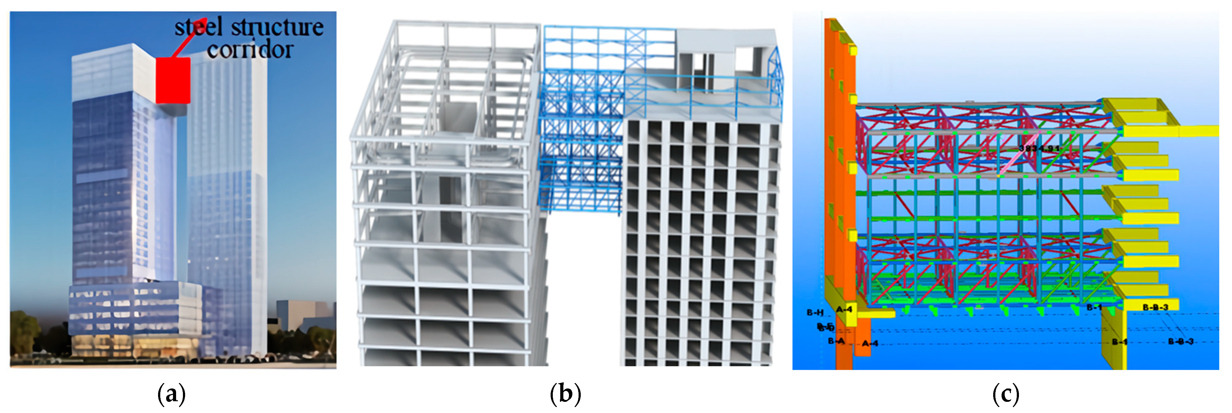
The Haiyue Center project in Quanzhou comprises two main structures, namely the apartment building and the office building, with a total height of 130 m. The office building is a reinforced concrete frame-core tube structure, while the apartment building adopts a shear wall structure. At a relative elevation of 115.55 m, a double-layer steel truss corridor is installed to connect the two main structures. The span of the corridor is 16.05 m, and the overall weight is about 75 t. The height and location of the steel structure corridor are depicted in Figure 1. As is shown in Figure 2c, the corridor includes a lower-level truss (platform height ranging from +115.55 m to 118.75 m) and an upper-level truss (platform height ranging from 125.15 m to 128.4 m), with an open space between the two levels. Additionally, a steel truss structural layer is erected between the elevations of 128.4 m and 134.69 m. On the office building site, the first three main trusses are equipped with three spherical sliding bearings, while on the apartment building site, they are rigidly connected to pre-embedded stiffening beams.

Figure 2.
Illustration of steel structure corridor configuration. (a) Geographical chart of steel structure corridor placement. (b) Relationship between the steel structure corridor and two towers. (c) Constituent elements.
In this study, numerical simulations of the lifting process of steel structure walkways are conducted employing the finite element software SAP2000. A comprehensive analysis model is established for the steel structure walkway during the lifting process, wherein the unified model encompasses both the lifted portion and the main structure. The SAP2000 software is utilized to analyze this unified model. It is worth emphasizing that this model incorporates the influences of wind loads and temperature fluctuations on the internal forces and deformations experienced by the main structure during the lifting process. Through this model, the safety and stability of the lifting process are ascertained, along with the evaluation of forces encountered during asynchronous lifting.
3.2. Structural Modeling and Load Application
The model calculation incorporates various load patterns, namely the dead load, temperature load, and wind load. Under the condition of a dead load, the load composition comprises the self-weight of the steel structure walkway and the counterweight load. The total weight of the lifting structure amounts to 75 tons (consisting of 65 tons for the lifting portion and 10 tons for the aluminum alloy curtain wall). However, for verification purposes, a weight of 100 tons will be employed. For comprehensive truss lifting, the load partial safety factor is taken as 1.3 × 1.15 = 1.5. It is important to note that spring constraints are set at the lifting points, including in vertical and horizontal directions. The stiffness value of the springs is set to 0.001 kN/mm.
To accommodate the structural nonlinearity and account for the second-order effects of gravity, the equilibrium state of the steel structure walkway is adjusted by applying a temperature load, which exerts thermal loads on the steel suspension cables [24,25,26]. This involves the inclusion of a temperature load in addition to the dead load and base load, while setting the initial stress of the steel suspension cables to zero.
Due to the constraints posed by the flexibility at the lifting points, the impact of the wind load is not taken into consideration during the lifting process of the walkway. However, the wind load is transmitted to the lifting platform through the steel guy wires. Hence, the effect of the wind load is considered when analyzing the internal forces and deformations of the lifting platform. As the main building block is the wind in the direction parallel to the truss span, only the wind load perpendicular to the truss span direction is taken into account. According to the regulations outlined in GB51162-2016 [27], the overall lifting construction of the steel structure walkway is prohibited when the wind force at the construction site reaches level six. Therefore, in the numerical simulation calculation process, the wind pressure corresponding to level six wind is adopted as the representative basic wind pressure value. The calculation formula for the wind load is provided as follows:
where ω0 is the representative basic wind pressure value (corresponding to level six wind), taken as 0.2 kN/m2; μ is the wind pressure variation coefficient at height z, taken as 2.322; μs is the shape coefficient for the wind load, taken as 0.8; βz is the wind vibration coefficient at height z, taken as 1.3. ωk = 0.483 kN/m2 , F = ωk × A = 0.483 × 38.5 = 18.5 kN < 1000 × 0.05 = 50 kN is calculated,, which complies with the specifications.
ωk = βz × μs × μz × ω0
3.3. Results and Analysis of the Modeling
An analysis of the obtained displacements, stability, and stresses from the simulation will be conducted to verify the feasibility of this lifting scheme.
3.3.1. Displacement Analysis
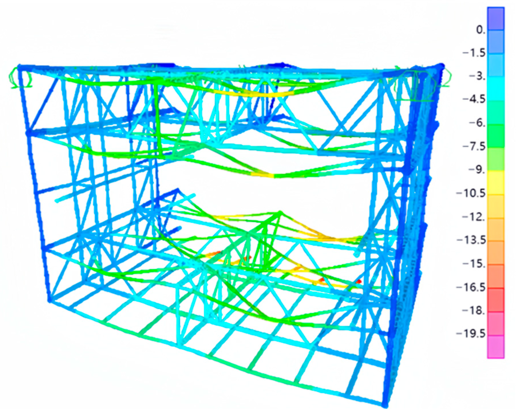
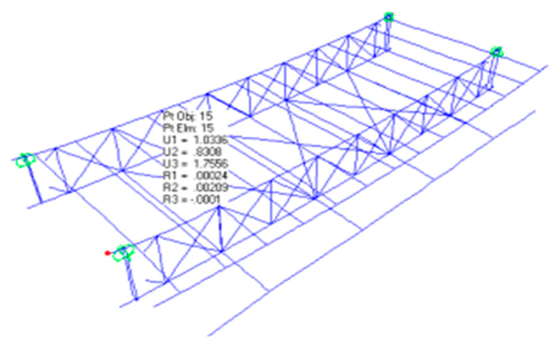
The self-weight of the steel structure walkway amounts to approximately 100 tons, whereas the wind load constitutes less than 5% of the vertical load. Nevertheless, due to the impact of the wind load, displacement occurs within the upper and lower structural centers of the steel structure walkway, resulting in noteworthy horizontal displacements during the lifting procedure. Figure 3 showcases the deformation diagram and the obtained displacement values of the steel structure walkway throughout the lifting process, as derived from the simulation.
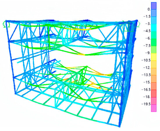
Figure 3.
Deformation during the lifting process of steel structure corridor.
Based on the deformation diagram depicted in Figure 3, the structure reveals noteworthy observations:
- (1)
- A notable vertical displacement is predominantly observed at the mid-span position of the walkway, reaching a maximum displacement value of 16.5 mm.
- (2)
- During the lifting process, a comprehensive analysis of the walkway’s displacement as a whole is crucial, accounting for the combined influences of the self-weight and wind load. The magnitude of this displacement significantly impacts the safety of the walkway. Consequently, it is imperative to implement appropriate measures to prevent potential collisions between the steel walkway and the surrounding buildings. Such collisions have the potential to damage existing structures and raise safety concerns.
Based on the simulation results in Table 1, the following measures can be undertaken to diminish the displacement encountered during the lifting process of the walkway and address safety concerns:

Table 1.
Displacement during the lifting process of steel structure corridor.
- (1)
- Incorporate anti-deformation trusses into the steel structure walkway. This measure reinforces the overall deformation performance, thereby ensuring the structural integrity of the walkway when subjected to wind load.
- (2)
- Introduce horizontal support members to the walkway, thereby augmenting the lateral stiffness of the structure. This addition facilitates the redistribution of horizontal internal forces in various directions, guaranteeing uniform internal forces within the steel structure walkway.
- (3)
- Increase the number of suspension cables and install temporary radial support members internally to enhance the structural stability of the walkway during the lifting process.
3.3.2. Stability Analysis
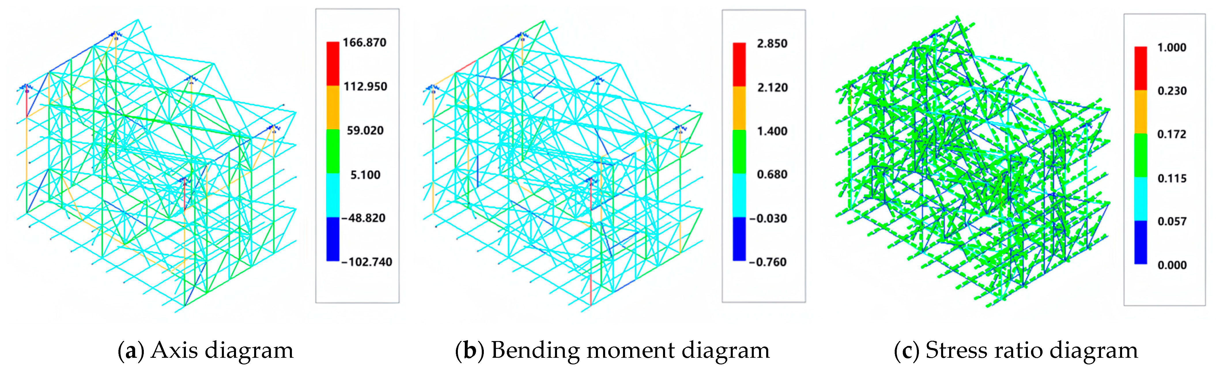
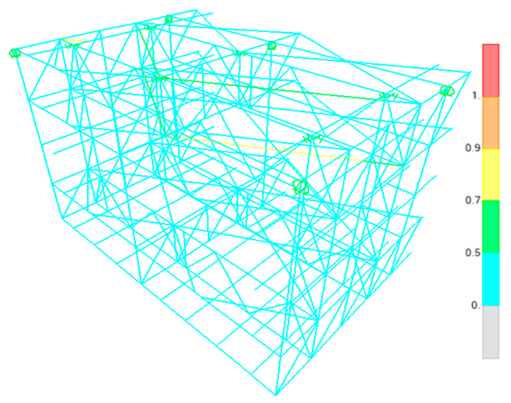
During the hoisting and lifting process of the steel structure corridor, the deformation and force distribution of the internal components of the corridor can be significantly influenced by the selection of different hoisting points and lifting positions. Consequently, the structural integrity may not be robust, leading to the occurrence of local instability and other related issues. Prior to hoisting and lifting operations, it is imperative to repetitively fine-tune the lifting point’s position through numerical simulations to ascertain the most optimal location. The simulation calculations provide a comprehensive cloud diagram depicting the axial force, bending moment, displacement, and stress ratio at the determined optimum lifting point, as shown in Figure 4.
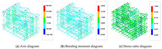
Figure 4.
Diagram illustrating internal force distribution in the steel structure corridor.
In accordance with the regulations stipulated in GB50017-2017 [28], the mid-span deflection of a single steel truss should not exceed L/400 (where L represents the span of the truss). The simulation results demonstrate that the maximum deflection observed during truss lifting amounts to approximately 19.5 mm, which is less than the calculated value of 40 mm (15,900/400). Furthermore, the stress ratio of the truss members remains below 0.5. Thus, it can be inferred that the stability of the truss meets the specified requirements. To ensure the stability of the steel structure corridor during the hoisting process and mitigate the risk of local instability, the following measures have been implemented:
- (1)
- Temporary anti-deformation trusses are installed within the steel structure corridor. These trusses effectively limit the occurrence of out-of-plane instability and enhance the stability of the structure throughout the hoisting operation.
- (2)
- Adequate counterweighting is performed symmetrically along the steel structure corridor. The weight distribution should be proportionate and typically ranges between 1% and 5% of the corridor’s own weight. Precise determination of the counterweight’s size and position is accomplished through numerical simulation, guaranteeing compliance with the required internal forces and deformation criteria.
- (3)
- Introducing a suitable number of diagonal webs at the connection points of the upper and lower floors is advisable. This measure serves to enhance the overall stability of the structure.
- (4)
- Adjustments are made to the system’s flow rate and pressure to ensure hydraulic system stability during the lifting process. Stringent control is exercised over the acceleration during both the initiation and termination of hoisting, thereby minimizing the impact of inertial forces on the lifting and hoisting procedures.
3.3.3. Stress Analysis
Due to certain errors in lifting construction equipment and personnel operations, it is challenging to ensure consistent speed and displacement for each lifting point during the hoisting of the steel structure corridor. The occurrence of asynchronous hoisting and lifting results is the consequence of change in the overall stress state of the steel structure corridor. Consequently, the internal forces of the steel structure corridor members under asynchronous hoisting and lifting conditions must be checked and calculated. Based on the distribution of internal forces within the structure, the limit values for lifting displacement and load differences at each lifting point are determined.
The stress levels are examined when asynchronous lifting occurs during the hoisting and lifting process of the steel structure corridor. Through numerical simulation, the asynchronous displacement difference of 25 mm is maintained for each lifting point, while the asynchronous lifting load is controlled within a range of 20%. The calculation results are listed in Table 2.
Table 2.
Summary of asynchronous lifting calculation.
Under the condition of asynchronous lifting, the internal force of the members of the steel structure corridor will be redistributed, and the stress cloud diagram of each member is shown in Figure 5.
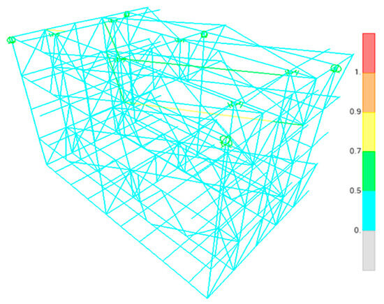
Figure 5.
Internal force diagram of rod components under asynchronous lifting conditions.
The analysis presented in Figure 4 reveals that the internal force distribution of the steel structure corridor members is indeed influenced to a certain extent under the condition of asynchronous lifting. Nevertheless, it is noteworthy that the stress of no member surpasses the permissible threshold, thereby complying with the requirements of asynchronous lifting. Consequently, the differential limit for lifting displacement and load at distinct lifting points is established. Specifically, the asynchronous displacement must be maintained below 25 mm, while the asynchronous lifting load should not exceed 20%. Only by adhering to these defined constraints can we guarantee that the steel structure corridor remains unaffected by substantial deformation and damage throughout the hoisting and lifting process.
4. Construction Procedure for the Case Study of Steel Structure Corridors under Wind Load
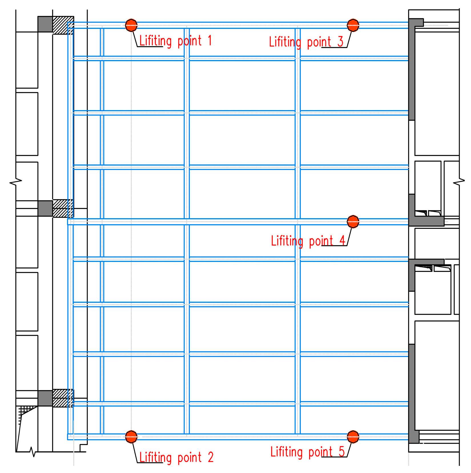
The main load-bearing structural system of the steel structure corridor in this project is composed of the three trusses on the first floor and the steel beams positioned in the middle. The remaining structure serves as an additional load during the installation process of the steel corridor, effectively enhancing the out-of-plane stability of the main truss. The force transmission within the force-bearing system of the overall structure is clearly defined, making the adoption of the overall hoisting and lifting construction method highly suitable. Considering the structural characteristics of the steel structure corridor in Haiyue Center project, it can be observed that it predominantly exhibits symmetrical attributes. Consequently, a total of five lifting points are arranged at both ends of each main truss (main steel beam), with an additional lifting point placed near the center. The spatial arrangement of these lifting points is depicted in Figure 6. The overall hoisting procedure can be outlined as follows: initially, the structural components are transported to the assembly platform and subsequently assembled to form a cohesive structure. To facilitate the hoisting and lifting operations, the assembly platform is directly positioned beneath the designated installation location. Once the assembly process is finalized, the structure can be hoisted directly to the intended height as per the design specifications and ultimately installed in its final position.
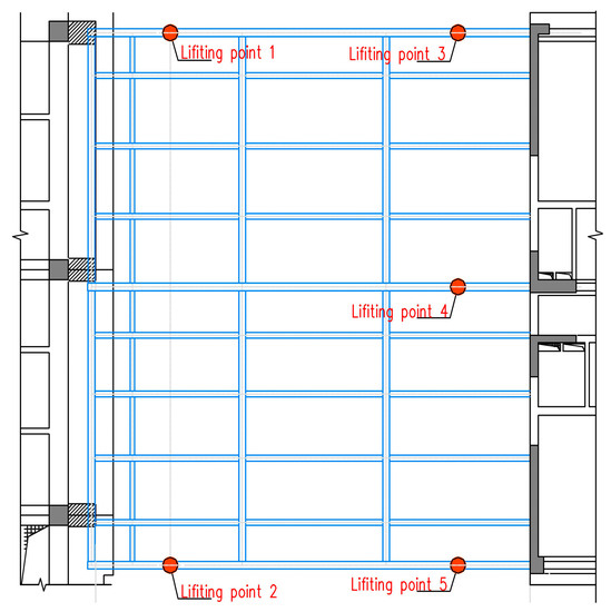
Figure 6.
Location distribution diagram of lifting points under the steel structure corridor.
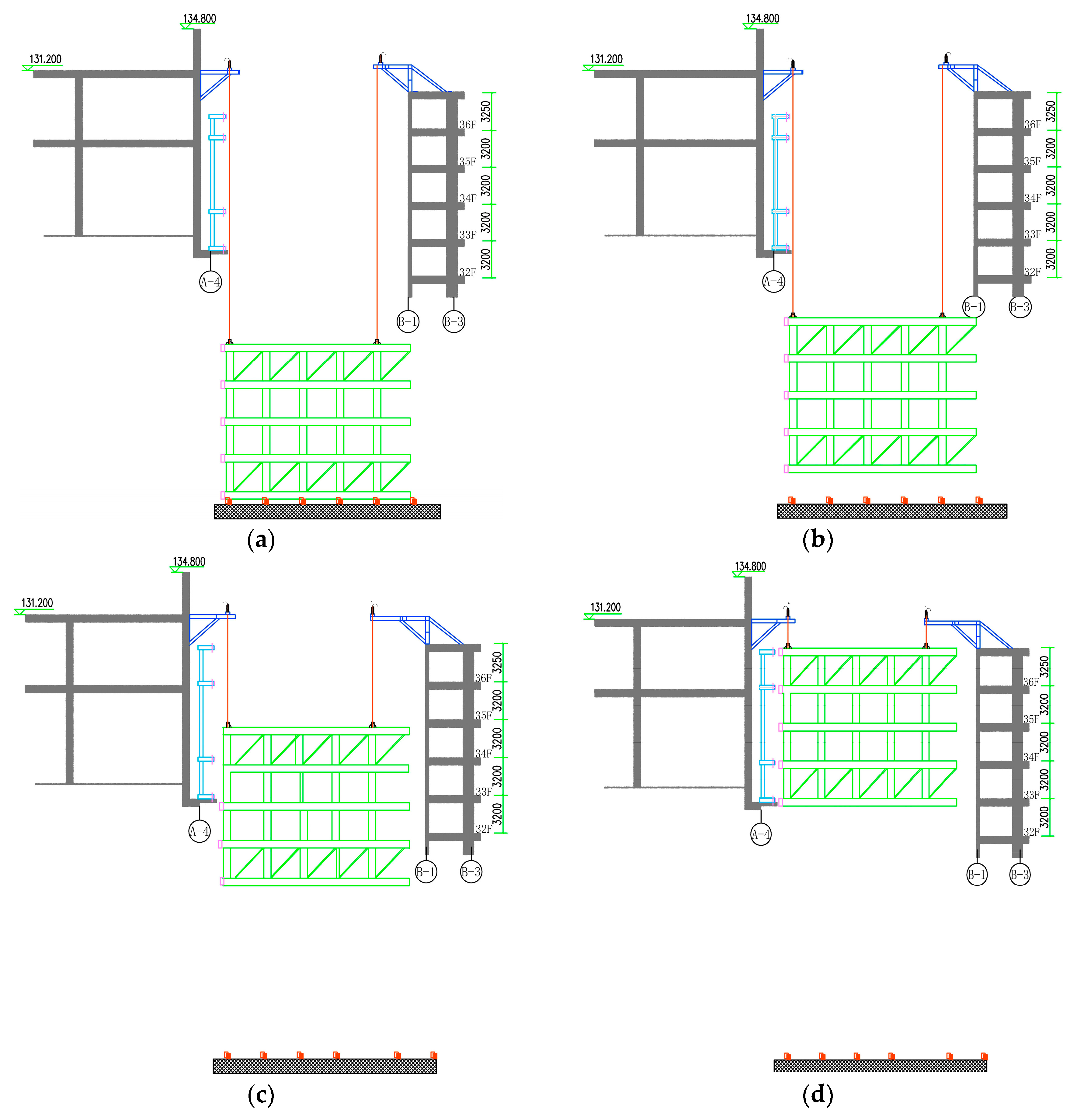
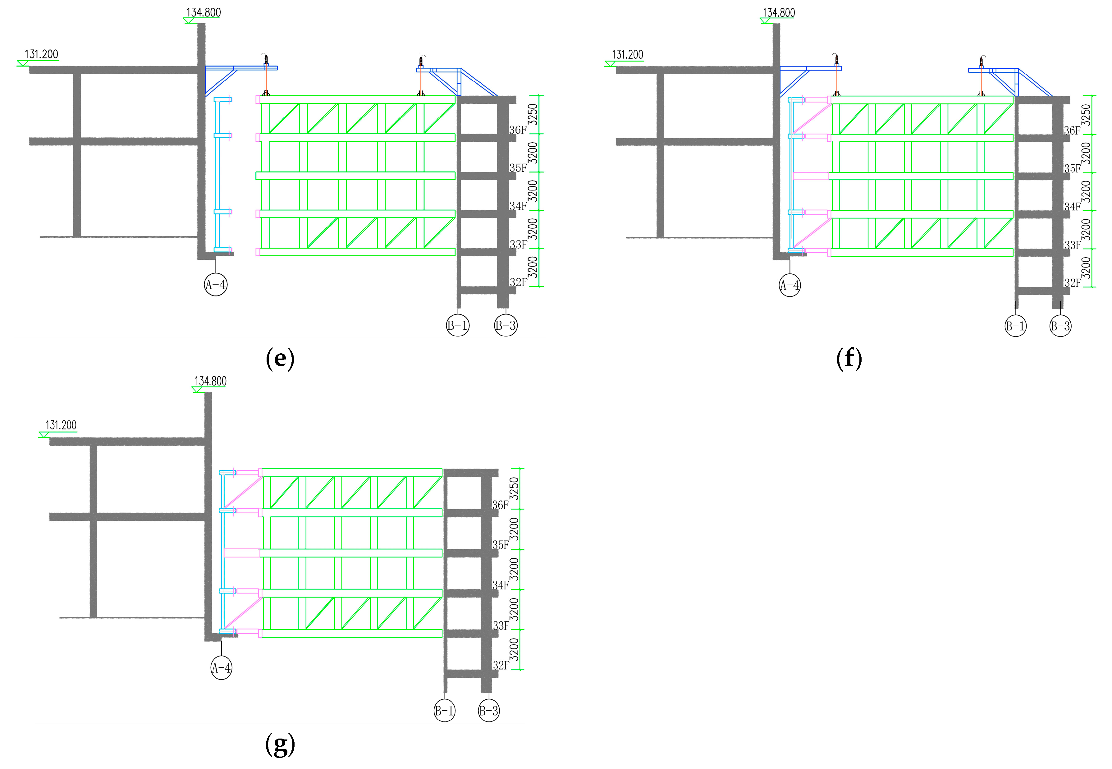
The lifting procedure is comprehensively delineated as follows:
- (1)
- The steel structure corridor trusses are assembled on the 7th floor of the podium, with a 100 mm offset from the concrete floor, located 115 m away from the office building’s side. Lifting platforms and lifters are installed. Subsequently, the hoist is connected and secured to the lower steel structure corridor using steel strands, as depicted in Figure 7a.
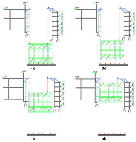
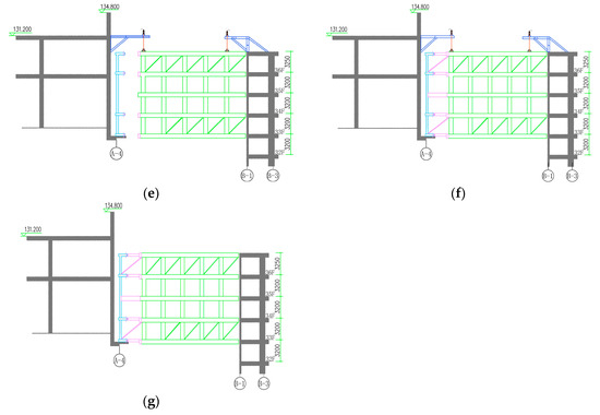 Figure 7. Schematic of lifting steps. (a) Connection between steel structure corridor and elevator. (b) Step loading. (c) Overall lifting of steel structure corridor. (d) Overall elevation to design elevation. (e) Push horizontally and laterally after lifting. (f) Welding rods. (g) Dismantling of temporary elevators.
 - (2)
- Once the steel structure corridor truss hoisting section is assembled, the hoist is prepared for gradual loading. The steel corridor is lifted as a whole, initially rising by 100 mm and then pausing the lifting operation. The hydraulic cylinder is locked, and the structure, temporary rods, lifting points, and lifting platform undergo a 12-h inspection to assess the normality of welding seams and deformations, as illustrated in Figure 7b.
- (3)
- The entire steel truss structure is lifted comprehensively. The adjusted height of each lifting point serves as the new starting position for hoisting, maintaining this posture until it approaches the desired elevation. The overall lifting speed is approximately 4 m/h, as demonstrated in Figure 7c.
- (4)
- As the overall synchronous lifting nears the design elevation with a 200 mm gap, the lifting speed is reduced. Fine-tuning of the lifter is then performed to accurately position the counterpart, and the hydraulic cylinder is locked, as shown in Figure 7d.
- (5)
- Employing a jack, all the lifter bases, along with the lifter and the truss, are synchronously pushed toward the side of the apartment building for around 400 mm, as depicted in Figure 7e.
- (6)
- Subsequently, butt welding takes place, followed by the installation of back-up rods, as illustrated in Figure 7f.
- (7)
- The lifter is unloaded, and the load is transferred to the prefabricated section. Finally, the temporary structure and the lifter are removed, as shown in Figure 7g.
The subsequent points outline the essential matters attention throughout the hoisting and lifting procedure:
- (1)
- The safety of hoisting and lifting the steel structure corridor under wind load conditions needs to be ensured. With a maximum hoisting height of 128.8 m and a weight of nearly 100 t, the steel structure corridor is susceptible to shaking and potential collisions with adjacent buildings under the influence of wind load. Given the proximity of the corridor to the main buildings, with a minimum distance of only about 200 m during the hoisting process, excessive lifting speed at each point relative to the wind speed onsite could result in collisions. Hence, it is crucial to analyze the safety concerns during the hoisting and lifting process of the steel structure corridor under wind load conditions and develop corresponding solutions.
- (2)
- The stability of the hoisting process for the steel structure corridor under wind load conditions is a critical consideration. The presence of wind load during hoisting and lifting can cause beam displacement and excessive stress in the steel structure corridor. This, in turn, leads to uneven deformation of the corridor, thereby affecting its overall stability. It is imperative to conduct a detailed analysis of the impact of wind load on the steel structure corridor and implement targeted control measures.
- (3)
- The force distribution problem for the steel structure corridor under wind load conditions during asynchronous lifting requires attention. Due to potential errors in hoisting construction equipment and operational procedures, it is challenging to maintain consistent speed and displacement at each hoisting point. Consequently, stress concentration and localized stress increases may occur at temporary support points. Significant disparities in lifting speed between different points could even result in structural instability. Therefore, it is necessary to evaluate and calculate the internal forces acting on the members of the steel structure corridor during nonsynchronous hoisting and lifting. This analysis will ensure that the structural members’ stress levels remain within allowable limits, provide corresponding limit values, and serve as a reference for the unloading process following the completion of the hoisting operation.
4.1. Preventive Measures against Collisions
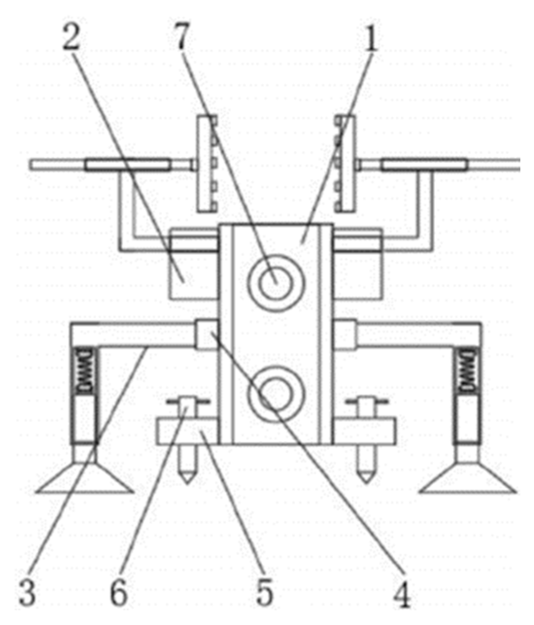
To address the potential collision risk during the hoisting process of the steel structure corridor resulting from wind load, a steel structure hoisting anti-collision device was incorporated into the construction process. This device aims to prevent the hoisting structure from experiencing significant arc movements caused by excessive wind speeds, as illustrated in Figure 8.

Figure 8.
Anti-collision device (1—main body of protective device, 7—fastening shaft, 2—alignment adjustment mechanism, 4—assembly shaft, 5—installation plate, 3—buffer mechanism, 6—ground pile).
On the outer surface of the protective device’s front end, a fastening shaft is positioned. Alignment adjustment mechanisms, assembly shafts, and mounting plates are situated on the outer surfaces of both sides of the steel structure corridor. The alignment adjustment mechanism is located at the upper end of the assembly shaft, while the mounting plate is situated at the lower end. Additionally, a buffer mechanism is installed on one side of the assembly shaft’s outer surface. This protective device effectively safeguards both the hoisting structure and the adjacent buildings throughout the construction process.
In addition to the anti-collision device, this study incorporates wind ropes at the four corners of the structural floors near the steel corridor. These wind ropes employ a 20mm-diameter steel wire rope and a two-ton hoist. One end is connected to the truss corner, while the other is attached to the primary structural column. By applying tension to the steel wire rope using the hoist and reverse chain, the steel corridor remains relatively stable under the influence of wind load, minimizing excessive shaking.
4.2. Process of Corridor Assembly
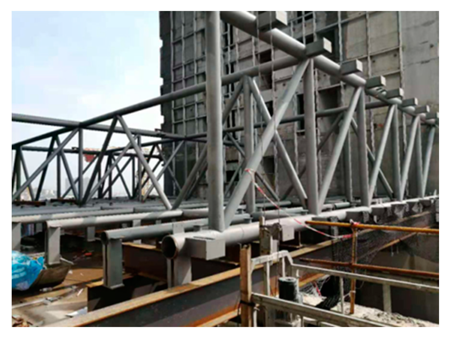
The assembly of the steel structure corridor is executed employing the onsite tower crane, adhering to the assembly sequence from west to east. Initially, the lower chord of the steel truss and the bottom steel beam are assembled, followed by the assembly of the vertical, oblique webs, and upper chord. Finally, the corridor’s middle and upper steel beams are sequentially assembled. To ensure structural integrity, the temporary reinforcement rods are incorporated alongside the rods of the steel structure corridor. Figure 9 illustrates the assembly process of the steel structure corridor.
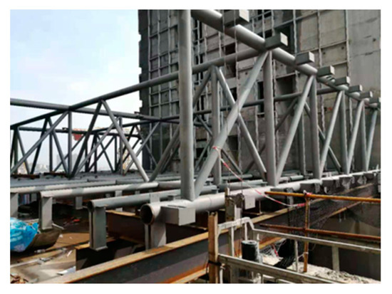
Figure 9.
Assembly process of steel structure corridor.
To ensure optimal stability of the steel structure corridor throughout the hoisting process, it is imperative to implement quality control measures during the assembly stage. Through a meticulous analysis of the hoisting and lifting process of the steel structure corridor under prevailing wind loads, it can be deduced that the primary factor influencing stability is the stiffness and precision of the steel structure corridor post-assembly. Therefore, the incorporation of anti-deformation trusses and diagonal web bars, along with appropriate counterbalancing during the hoisting construction process, becomes essential to averting potential destabilization of the corridor. The specific methods employed are as follows:
Firstly, three temporary anti-deformation trusses were erected during the assembly of the corridor. These trusses effectively restrict the out-of-plane deformation of the corridor while simultaneously enhancing its structural integrity. Secondly, crucial control points are designated during the assembly process. These points serve as reference markers during component assembly, and the horizontal projection of these control points is delineated to ensure the utmost accuracy in the assembly process. Thirdly, a specific number of diagonal web bars are installed at the connecting web bars. Simultaneously, tire frames are welded onto the platform. Furthermore, the vertical elevation of the control points is measured to guarantee the precise positioning of the chord bars.
4.3. Linkage between the Corridor and the Lifting Apparatus
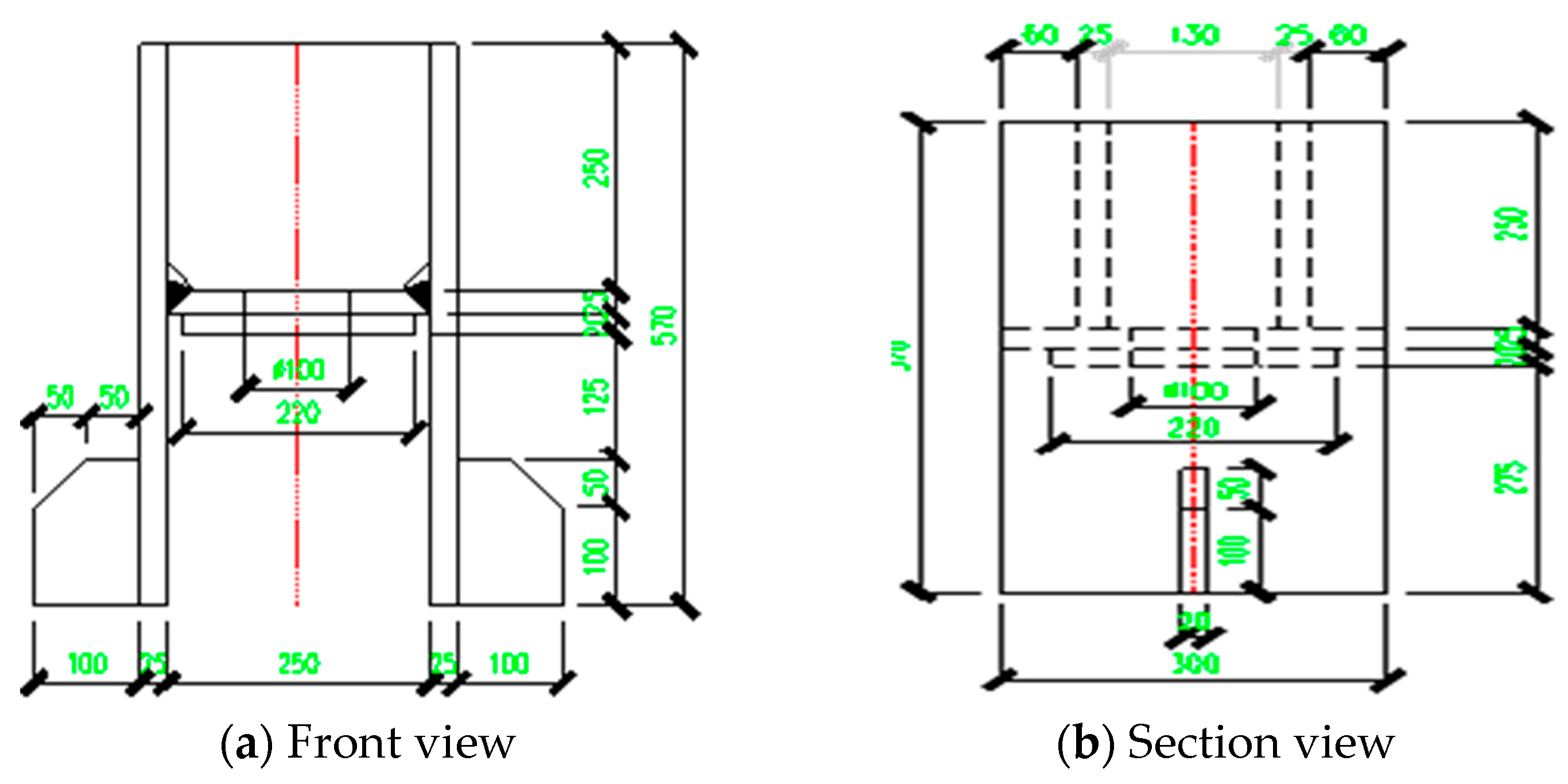
The lowering point is mainly in the form of welding a special lifting device on the upper surface of the upper chord member of the steel structure corridor truss. The connection mode and position of the lifting equipment and the upper chord of the truss are shown in Figure 10.
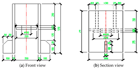
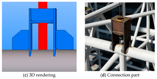
Figure 10.
Structure of the lifting appliance.
Based on the preceding finite element simulation, it is evident that the hanger’s connection to the steel structure corridor experiences predominantly tensile stress, while the connection to the sling is primarily subjected to compression. Hence, a thorough inspection of the welding quality at these two connection points is imperative. During the hoisting and lifting process of the steel structure corridor, the spreader material employed is Q345B steel, which adheres to the construction criteria for hoisting and lifting operations.
4.4. Hierarchical Loading and Hoisting
Regular deformation observation of the tower structures on both sides should be carried out before the hoisting and lifting of the steel structure corridor in order to comprehend the development and regulation of its deformation. Throughout the hoisting and lifting process, continual monitoring of the height and height difference of the steel structure corridor is essential to ensure that the height difference of each lifting point remains controlled within L/500 (where L represents the span of the steel structure corridor). In the event that the load or height difference at any lifting point exceeds permissible limits, immediate adjustments or cessation of lifting must be implemented. Resumption of lifting operations is only permitted once the fault has been examined and rectified. The stability of the hydraulic system is guaranteed by adjusting the pressure during the hoisting and lifting of the steel structure corridor. Furthermore, stringent control over acceleration during the initiation and braking phases of the hoisting process is crucial to minimizing the impact of inertial force on the overall lifting procedure. Figure 11 illustrates the staged loading and lifting process of the steel structure corridor.

Figure 11.
Graded loading and lifting of the elevator.
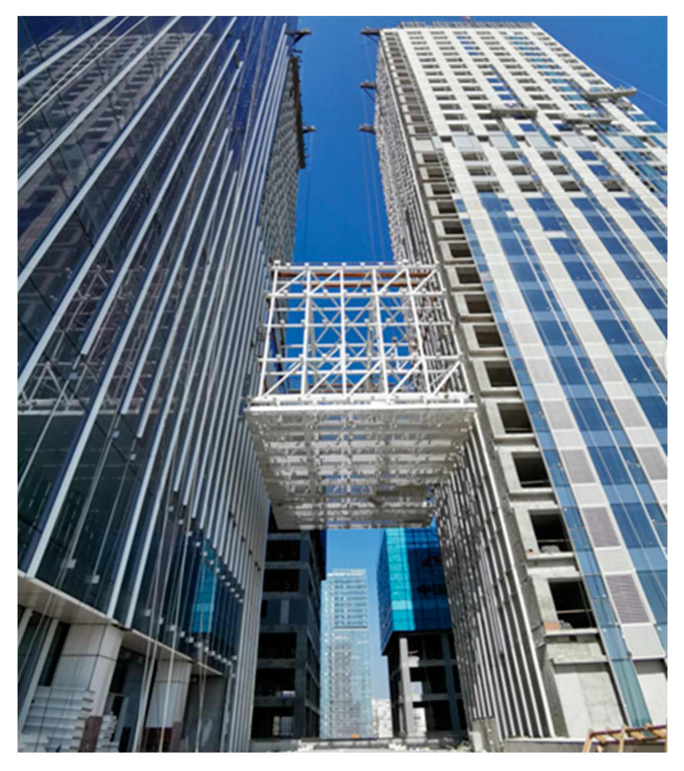
Fine adjustments should be made to each lifting point of the corridor to elevate it to the designated position. Subsequently, the work of the hydraulic lifting system equipment should be suspended, and it should be maintained in a stationary lifting state. The chords located in the middle section of the main truss, as well as the chords at both ends, are then subjected to butt welding and secured. Lastly, the diagonal web bar is installed to establish a stable structural system capable of bearing overall forces. This integration is achieved by aligning it with the segmented structures installed at both ends, as depicted in Figure 12.
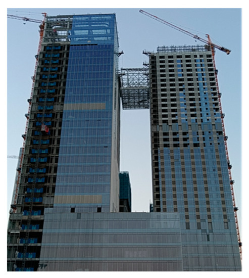
Figure 12.
Lifting the corridor to the design height.
4.5. Dismantling of Corridor Support
Once the steel structure corridor has been raised to its designated height through hoisting, the installation of steel trusses follows suit. Subsequently, the hydraulic lifting system equipment is disassembled, and appropriate temporary measures are implemented to ensure the stability of the steel structure corridor. Once the installation of the steel structure truss is finalized, a comprehensive inspection of the entire structure is imperative before removing the supporting frame. The temporary support frame can only be dismantled after the inspection confirms its correctness. As the temporary support frame is gradually dismantled, the load initially borne by it is progressively transferred to the overall structure, ultimately allowing the structure to sustain its own forces. Figure 13 illustrates the process of horizontal lateral push and installation.
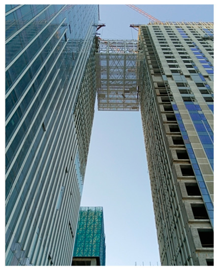
Figure 13.
Horizontal lateral pushing and structural unloading.
To account for errors arising from construction equipment and personnel operations during hoisting, it is necessary to conduct the unloading of the structure in multiple stages. By means of numerical simulation, the asynchronous lifting of the steel structure corridor has been examined. The results indicate that as long as the asynchronous displacement of each lifting point remains within 25 mm and the asynchronous lifting load is kept at approximately 20%, the stress experienced by all structural members’ remains below the permissible threshold. This ensures that the strength requirements for the components of the steel structure corridor are met even under asynchronous lifting conditions. Thus, it is recommended to maintain control over the asynchronous displacement during the unloading process, limiting it to within 10 mm, and to exercise a 10% threshold for asynchronous unloading during operation.
4.6. Validation of Finite Element Findings
To ensure the precise installation of the steel structure corridor, it is imperative to eliminate errors during the installation process. The primary sources of errors can be attributed to the following two factors: Firstly, the alignment may be compromised due to the downward deflection and deformation of the truss upon lifting into position. As depicted in Figure 14, a minor deflection of approximately 3 mm is observed at the end of the main truss during the lifting process. Although the deflection value is small, it can be rectified by utilizing welding techniques, thereby mitigating the impact of the downward deflection on the corresponding components. This approach guarantees that the welding quality of the components adheres to the prescribed standards.

Figure 14.
Steel corridor truss lifting construction deflection value.
Secondly, errors arise from the installation’s positioning. The permissible deflection angle for the steel strand must not exceed 1.5°. During the installation process, it is advisable to begin by installing the lifting platform at the designated hoisting point. Subsequently, the position of the lower hoisting point should be determined in accordance with the location of the hoisting point. This ensures that the verticality of the line connecting the upper and lower hoisting points meets the specified requirements. When lifting the truss into position, any height deviation in the vertical direction can be adjusted by finely tuning the lifter, while the horizontal deviation necessitates the use of a guide chain for pulling purposes. Once the positioning adjustment is promptly completed, a temporary connection is established to prevent any movement during the alignment of the corridor, thereby satisfying the alignment welding criteria. It is crucial to maintain the guide chain in a taut state until the butt welding is finalized, at which point both the guide chain and temporary connection can be removed.
During the hoisting and lifting process, the wind speed onsite ranges from 1.6 to 7.9 m/s, resulting in evident wind load effects on the construction steel structure corridor. Notably, the corridor noticeably oscillates shortly after departing the assembly platform due to the influence of the wind. However, the installation of pre-installed anti-collision devices and wind ropes effectively safeguards the structural integrity.
Based on the aforementioned analysis and calculations of the steel structure corridor’s stability during the hoisting and lifting process under wind load, it is determined that the maximum downward deflection of the corridor throughout the entire lifting procedure amounts to 19.5 mm, measured from the initiation of hoisting until reaching the intended design elevation during final lifting. Onsite measurements indicate a maximum deflection of the steel structure truss at 24.3 mm, which is below the threshold of L/400 = 40 mm, closely aligning with the results obtained from numerical simulations. This demonstrates that the integrity and stability of the steel structure corridor during the hoisting process align with the anticipated design expectations, affirming the effectiveness of the implemented control measures.
5. Conclusions
This study explores the mechanical responses, safety, stability, and construction guidance during the integral hoisting process of steel structure corridors between super-tall buildings under wind load conditions. Through theoretical analysis and numerical simulation methods, the study assesses and addresses the impact of wind loads on collisions and deformations during the hoisting of steel structure corridors. The integral hoisting and construction of steel structure corridors in two super-tall buildings within the Haiyue Center project in Quanzhou City were taken as practical case studies. SAP2000 software was utilized to comprehensively simulate and inspect the cases. This included a detailed analysis of simulation results, encompassing corridor displacement, stress distribution, and overall stability. Significant thresholds for allowable displacement and load differences at each lifting point during the integral lifting process were established. Subsequently, relevant construction control measures were developed to enhance safety and stability during the steel structure corridor lifting process under wind load effects. Scientific recommendations and references for the hoisting and construction process under wind load effects for similar cases were provided. Therefore, the conclusions drawn are as follows:
- (1)
- Safety of steel structure corridors hoisting under wind load
Safety during the hoisting process of steel structure corridors under wind load is critical. In the integral hoisting process, the lack of necessary constraints and support within the horizontal plane of the corridor can lead to sensitivity to wind load, especially at heights exceeding 100 m. To prevent structural oscillations due to wind load during the lifting process, safety control measures were taken. Collision-prevention devices were installed on the main structure to avoid collisions resulting from large swings induced by strong winds, thus preventing damage to both sides of the building and the steel structure corridor.
- (2)
- Stability of steel structure corridors hoisting under wind load
Issues related to excessive displacement and stress in the beams of steel structure corridors can lead to uneven deformation during the hoisting process. Quality control measures were implemented during assembly to address this concern. Temporary anti-deformation trusses were set up during the assembly to effectively constrain out-of-plane deformations of the steel structure corridor and enhance its overall stability. Key control points were marked during assembly and used as reference points for component assembly to ensure precision during the process. Additionally, diagonal support members were placed at the connection points, and the framework was welded to the platform to maintain vertical alignment, ensuring the correct positioning of tension components. The integration of diagonal support components connecting the upper and lower trusses not only prevents in-plane instability in the steel structure corridor but also ensures the stability of the entire hoisting operation.
- (3)
- Stress issues of steel structure corridors during asynchronous hoisting under wind load
Structural unloading should be carried out in a graded manner. Numerical simulations have revealed that when the asynchronous displacement at each lifting point is around 25 mm and the asynchronous lifting load is kept at approximately 20%, the stress in the members remains below the allowable limit. Furthermore, during the unloading process, the asynchronous displacement should be controlled within 10 mm, and the asynchronous unloading should be controlled within 10%.
Author Contributions
R.R.: conceptualization, methodology, writing—original draft preparation, formal analysis, and project administration; M.L.: conceptualization, methodology, and writing—original draft preparation; C.J.: methodology, writing—original draft preparation, formal analysis; J.W.: methodology, writing—original draft preparation, formal analysis; Y.L.: methodology, formal analysis, and project administration. All authors have read and agreed to the published version of the manuscript.
Funding
This research was funded by the Natural Science Foundation of Fujian Province (No. 2023J01109), the Social Science Foundation of Fujian Province (No. FJ2022C038), and the Xiamen Federation of Social Science Associations and Xiamen Academy of Social Sciences (No. 2022D08, No. 2023D10).
Institutional Review Board Statement
The study did not require ethical approval.
Informed Consent Statement
Informed consent was obtained from all subjects involved in the study.
Data Availability Statement
No new data were created or analyzed in this study. Data sharing is not applicable to this article.
Conflicts of Interest
The authors declare no conflict of interest.
References
- Karoki, K.E.; Shen, L.G.; Gong, J.H. Capacity analysis, investigations and retrofitting of a long span steel grid hangar. Eng. Fail. Anal. 2017, 78, 1–14. [Google Scholar] [CrossRef]
- Song, W.J.; Ma, C.; Yuan, R.W.; Liang, Z.Y. Analysis and design of linked structure. Build. Struct. 2011, 41, 55–58. (In Chinese) [Google Scholar]
- Lozinsky Cara, H.; Stopps, H.; Touchie Marianne, F. In-situ performance of a pressurized corridor ventilation system: A long-term study in a high-rise multi-unit residential building. J. Build. Eng. 2023, 70, 106320. [Google Scholar] [CrossRef]
- Wang, W.J.; Zhang, M.S.; Ma, Z.Y.; Gao, J.; Liu, Z.B. Key technique study for seismic performance design of an upper air connecting corridor. Build. Struct. 2018, 48, 36–41. (In Chinese) [Google Scholar]
- Zhang, M.L.; Chen, Y.R.; Zhou, P.; Zhuang, Z.C. Application of integral lifting technique in long-span steel truss construction. Steel Constr. 2018, 33, 94–98. (In Chinese) [Google Scholar]
- Lacey, A.W.; Chen, W.; Hao, H.; Bi, K. Effect of inter-module connection stiffness on structural response of a modular steel building subjected to wind and earthquake load. Eng. Struct. 2020, 213, 110628. [Google Scholar] [CrossRef]
- Zhou, C.L.; Li, X.W.; Sun, J.K.; Wu, Y.G. Lift monitoring and analysis of multi-storey corridors in buildings. Autom. Constr. 2019, 106, 102902. [Google Scholar] [CrossRef]
- Tian, L.M.; Hao, J.P.; Wei, J.P.; Zheng, J. Integral lifting simulation of long-span spatial steel structures during construction. Autom. Constr. 2016, 70, 156–166. [Google Scholar] [CrossRef]
- Lu, Y.; Zhu, Y. Integrating Hoisting Efficiency into Construction Site Layout Plan Model for Prefabricated Construction. J. Constr. Eng. Manag. 2021, 147, 04021130. [Google Scholar] [CrossRef]
- Shen, Y.B.; Luo, Y.Z. Accumulative Sliding Construction Method for Large-Span Latticed Shells. J. Constr. Eng. Manag. 2010, 136, 1154–1157. [Google Scholar] [CrossRef]
- Jeong, Y.J.; Koo, H.B.; Kim, H.Y. Efficient erection method of cantilever bridge deck using ribbed steel form bolted to girder. In Proceedings of the Composite Construction in Steel & Concrete VI, Tabernash, CO, USA, 20–24 July 2008; ASCE: Reston, VA, USA, 2008; pp. 766–777. [Google Scholar]
- Rausch, C.; Nahangi, M.; Perreault, M.; Haas, C.T.; West, J. Optimum Assembly Planning for Modular Construction Components. J. Comput. Civ. Eng. 2017, 31, 04016039. [Google Scholar] [CrossRef]
- Qin, J.J.; Tan, P. Design method of innovative box connections for modular steel constructions. J. Build. Eng. 2022, 57, 104820. [Google Scholar] [CrossRef]
- Ahn, H.; Lee, C.; Kim, M.; Kim, T.; Lee, D.; Kwon, W.; Cho, H. Applicability of smart construction technology: Prioritization and future research directions. Autom. Constr. 2023, 153, 104953. [Google Scholar] [CrossRef]
- Ruan, R.; Chen, Y.; Lin, W.; Wei, L.; Huang, J. The Construction Technology of Column Replacement Integral Accumulation Sliding at Uneven Elevation for Steel Structures. Buildings 2023, 13, 1958. [Google Scholar] [CrossRef]
- Zhang, M.; Deng, C.; Song, Z. Application of Cumulative Pushing and Sliding Technology in Large Span Steel Truss Construction. Construciton Technol. 2020, 49, 33–36. (In Chinese) [Google Scholar]
- Zhao, Y.; Wang, J.F.; Pang, M. Integral Lifting Project of the Qifeng Bridge. J. Perform. Constr. Facil 2012, 26, 353–361. [Google Scholar] [CrossRef]
- Kim, T.; Lim, H.; Cho, H.; Kang, K.I. Automated Lifting System Integrated with Construction Hoists for Table Formwork in Tall Buildings. J. Constr. Eng. Manag. 2014, 140, 04014049. [Google Scholar] [CrossRef]
- Lu, C.T.; Yang, Z.; Li, P.F.; Xu, Q.; Chen, L.; Zhang, C. Integral sliding of a 800 T steel roof truss for a cultural and art center building. Case Stud. Constr. Mater. 2022, 17, e01345. [Google Scholar] [CrossRef]
- Xu, C.; Xu, L.; Zhou, J. Integral Lifting of a Three-Span Continuous Beam Bridge. J. Perform. Constr. Facil. 2015, 29, 04014117. [Google Scholar] [CrossRef]
- Bai, L.; Zhang, Y. Nonlinear dynamic behavior of steel framed roof structure with self-centering members under extreme transient wind load. Eng. Struct. 2013, 49, 819–830. [Google Scholar] [CrossRef]
- Wang, Z.; Rajana, K.; Corfar, D.A.; Tsavdaridis, K.D. Automated minimum-weight sizing design framework for tall self-standing modular buildings subjected to multiple performance constraints under static and dynamic wind loads. Eng. Struct. 2023, 286, 116121. [Google Scholar] [CrossRef]
- Hareendran, S.P.; Alipour, A.; Shafei, B.; Sarkar, P. Characterizing Wind-Structure Interaction for Performance-Based Wind Design of Tall Buildings. Eng. Struct. 2023, 289, 115812. [Google Scholar] [CrossRef]
- Benitez Manuel, A.; Darwin, D.; Donahey, R.C. Deflections of composite beams with web openings. J. Struct. Eng. 1998, 124, 1139–1147. [Google Scholar] [CrossRef]
- Nie, J.G.; Cai, C.S. Steel-concrete composite beams considering shear slip effects. J. Struct. Eng. 2003, 129, 495–506. [Google Scholar] [CrossRef]
- Nie, J.G.; Fan, J.S.; Cai, C.S. Stiffness and deflection of steel-concrete composite beams under negative bending. J. Struct. Eng. 2004, 130, 1842–1851. [Google Scholar] [CrossRef]
- GB51162-2016; Technical Code for Integral Lifting of Heavy Structure and Equipment. Ministry of Housing and Urban-Rural Development of the People’s Republic of China: Shanghai, China, 2016. (In Chinese)
- GB 50017-2017; Standard for Design of Steel Structures. Ministry of Housing and Urban-Rural Development of the People’s Republic of China: Beijing, China, 2017. (In Chinese)


Disclaimer/Publisher’s Note: The statements, opinions and data contained in all publications are solely those of the individual author(s) and contributor(s) and not of MDPI and/or the editor(s). MDPI and/or the editor(s) disclaim responsibility for any injury to people or property resulting from any ideas, methods, instructions or products referred to in the content. |
© 2023 by the authors. Licensee MDPI, Basel, Switzerland. This article is an open access article distributed under the terms and conditions of the Creative Commons Attribution (CC BY) license (https://creativecommons.org/licenses/by/4.0/).