Article

Strength of Hybrid Steel-BFRP Reinforced Concrete Beams with Openings in the D-Region Strengthened Internally and Externally

1
Department of Civil Engineering, Faculty of Engineering, Suez University, Suez 8151650, Egypt
2
Department of Civil Engineering, Faculty of Engineering, South Valley University, Qena 83523, Egypt
*
Author to whom correspondence should be addressed.
Buildings 2023, 13(10), 2522; https://doi.org/10.3390/buildings13102522
Submission received: 4 September 2023 / Revised: 3 October 2023 / Accepted: 4 October 2023 / Published: 5 October 2023

Abstract

:
The opened beams always confused the designers due to the guidelines missing. In this research, six hybrid beams reinforced with mixed steel and basalt fiber-reinforced polymer (BFRP) bars and having constant cross-sections of 150 mm × 300 mm and a clear span of 1800 mm were cast and tested under a four-point loading setup. Generally, five beams had symmetrical rectangular openings with dimensions of 150 mm × 250 mm located at a distance of 250 mm (equivalent to the beam effective depth) from the beam support, while an additional solid beam served as a control. The studied parameters included the effect of using internal reinforcement (steel or BFRP bars) provided adjacent to the opening sides or by incorporating an external BFRP sheet around the opening corners. Also, double enhancement with internal steel reinforcement bars together with external strengthening BFRP sheet was investigated. The relevant results showed that the opened beam without enhancement lost 75% of the maximum load compared with the solid beam. Placing internal steel or BFRP bars around the openings increased the maximum load by 62% and 60%, respectively, compared to the non-enhanced opened beams. Using an external BFRP sheet to strengthen the opening corners of the beam enhanced the maximum load by 76% compared with the non-enhanced opened beam. Consequently, by combining both the internal steel reinforcement and external BFRP sheet around the openings, the maximum load increased by 137% compared with the non-enhanced opened beam. Ultimately, a numerical analysis of the three-dimensional finite element model was performed to confirm the experimental findings, and the relevant results showed compatibility correlations with the experimental ones. Also, the effect of various parameters such as BFRP reinforcement ratio and number of BFRP sheet layers around the openings was investigated by adapting the validated numerical model.

1. Introduction

The usage of steel reinforcement in structural elements, whether columns, slabs, or beams, has been prevalent since ancient times. Despite the defects of steel, such as rust, in addition to poor behavior after the yielding stage, it is considered to have elastoplastic behavior. On the contrary, fiber-reinforced polymer (FRP) is considered to have elastic behavior in all loading phases, in addition to high strength. For these reasons, hybrid reinforcement is the future in reinforcing various structural elements because it provides the benefits of both used materials (steel and FRP). FRP generally has many advantages and few disadvantages, and it is generally well-known in the academic community. However, FRP composite material is an excellent choice for exterior reinforcement due to its superior properties, such as high stiffness and strength, ease of installation, applicability without disturbing the existing functionality of the structure, and the non-corrosive and non-magnetic nature of the material along with its resistance to chemicals.
The use of FRP has become a natural development in reinforcing various structural elements. Many studies used FRP composites as an internal reinforcement or as an external strengthening, and they showed outstanding performance in resisting the loads. Naturally, researchers tended to study the behavior of BFRP as a main reinforcement in beams experimentally or numerically, such as in [1,2,3]. The relevant results showed the distinctive performance of the BFRP, which, in addition to being environmentally friendly, has relatively stable properties compared to other FRP materials but with higher vertical deflection in comparison to carbon fibers. This was also confirmed by [4].
Another study by [5] investigated the flexural behavior of beams reinforced with BFRP bars under the effect of concentrated loads, and the analytical parametric analyses showed that the yield strength and amount of steel reinforcement increased along with the yielding and ultimate moments. As yield strength and the amount of steel reinforcement increased, the ultimate curvature, curvature ductility, and energy dissipation of the entire stage decreased in the event of under-reinforced failure. In [6], the authors studied the flexural capacity of BFRP beams. Shear and longitudinal reinforcement were accomplished using steel and BFRP bars. The results show that the BFRP bar usage caused beam failure due to concrete crushing in the top compression fibers. The authors also recommended designing the beams to fail by concrete crushing, avoiding the danger of brittle failure of the BFRP bars in the beams reinforced with BFRP bars. Hence, there has been a tendency to use hybrid reinforcement with double reinforcements of steel and FRP bars. This type of hybrid reinforcement is interesting, but there is a lack of structural behavior research. On the other hand, [7,8,9] studied the behavior of hybrid reinforcements for different structural elements, and the results showed significant enhancement in the structural performance. The hybrid reinforcement in concrete beams can achieve 91% to 97% of the ultimate bending moments in comparison to beams reinforced with steel reinforcement [10]. That encourages the researchers to investigate more behaviors of the hybrid reinforcements. The effect of the hybrid reinforcement ratio was investigated by [11]. The findings show that adding BFRP bars to the side of a beam under maximum tension can enhance the beam’s structural performance after steel yielding. Also, the bond properties of the employed FRP bars influence the beams’ flexural capacity and post-yielding stiffness.
Reinforced concrete (RC) structures are sometimes subjected to modification during their service life, making web openings in the RC. Beams are often required to accommodate basic services such as air conditioning ducts, water supplies, electricity, and heating ductwork. Transverse openings in the RC beams are a potential source of strength loss. Consequently, the openings in the existing RC beams lead to an interruption in the normal flow of stresses, which reduces the beam’s shear capacity and stiffness and leads to premature cracking of the concrete, especially around the opening corners. Depending on the shear span-to-depth ratio, shear design guidelines in many building codes today distinguish between zones in reinforced concrete beams. Short-span regions are defined as D-regions, where D stands for deep or disturbed. In these regions, it is considered that load transfer follows an arch action mechanism and that strain distribution is nonlinear. The B in B-regions refers to either the beam or Bernoulli, who proposed the linear strain distribution in beams, in which larger shear spans transfer load by beam action. D-regions are areas in RC beams where the shear span is less than twice the depth and are thought to be dominated by arch action. In the current study, the openings were conducted in the most critical zone (D-region).
These openings may have various shapes, including diamond, trapezoid, triangular, rectangular, circular, and square shapes. However, rectangular and circular holes are the most used. The web openings may be placed in high flexures or high shear zones, such as near the mid-span of beams or places close to the column support in RC beams. In the current research, the focus was on the critical shear zone. On the other hand, the openings are classified according to the lo/hc aspect ratio by [12], where lo is the opening’s length and hc is the larger of the opening’s depth of the bottom or top chord. Rectangular web openings in the shear zones of RC beams are classified as small, large, or very large. Small openings are those with an aspect ratio of less than 1.5, whereas large openings have an aspect ratio of 1.5 to 4.0. However, very large openings have an aspect ratio of more than 4.0. Based on those, the opening in our study was classified as large. Ref. [13] studied the opened beam with large web openings. The study applied the direct stiffness method for solid and opened members. The relevant results showed that the deflection and support reactions are in excellent agreement with the findings in [14]. Hence, the approach provides adequate data for incorporating openings.
Many researchers study the effect of openings through the beam web and the deterioration present in the shear capacity, which depends on the position of the opening and whether it passes through the path between the load and the support and finally leads to reducing the load capacity of the beam. Consequently, cracking and ultimate loads decreased, and enhancing action became more pronounced as opening dimensions increased. To prevent this decrease in shear and bending capacity, additional reinforcement must be added around the opening in the form of internal reinforcement or external strengthening. The author in [15] stated that the stiffness and ultimate strength of the reinforced concrete beam decreased dramatically when an opening was present within its shear zone. Because of the concentration of stress, several cracks appear at the opening corners, and because of the lack of shear strength, diagonal cracks appear along the upper and lower chords. Failure in this instance occurs as a diagonal shear failure in the upper and lower chords. So, it is more effective to externally strengthen a beam opening with steel plates or carbon fiber-reinforced polymer (CFRP) sheets than to reinforce internally with internal steel reinforcement because the section at the opening is made stiffer by the external material and the material choice for external strengthening determines how much the section stiffness increases. In this direction, it has been emphasized that adding reinforcements to the area around the opening is a great method to restore the strength and stiffness of the beam, and that was also confirmed by [16]. Numerous researchers have noted that this is necessary to mitigate the detrimental effects of stress concentrations around the openings and prevent the beam from failing prematurely. The authors in [17] investigated the effect of using pre-stressing bars around the openings to enhance the shear strength capacity. The relevant results showed that the method used is capable of restoring the total capacity of opened beams as unopened beams.
The ultimate load capacity of the beam increases significantly if the openings are near the mid-span tension side or closer to the compression side near the supports, as reported by [18]. Also, the ultimate load capacity of the beam is affected by a web opening at a high-moment side, and this opening affects the failure load. Consequently, the ultimate load capacity of beams with a large opening is lower than that of beams with several narrow openings having the same equivalent area. The results showed that by strengthening the openings’ corner sides, the ultimate load capacity of the beams increased. Also, if the length of the reinforcement provided at the bottom and top of the opening is insufficient for anchorage, horizontal web reinforcement should be added along the beam. The authors in [19] noted that the opening size governs the beam failure, and FRP strengthening material does not enhance the ultimate load capacity of the opened beams. However, the beam capacity is reduced by 39% for a non-strengthened beam opening with a 100 mm opening height and a 0.15 beam width. Hence, the maximum load capacity of a non-strengthened beam with an opening of 100 mm width and a height of 0.38 is reduced by 33%. Further, FRP-wrapped beams exhibit debonding of the FRP wrapping, which causes them to tear along the diagonal cracks. Also, initial cracks in the flexural zone instead of the opening zone cracks appeared in the FRP wrapping around the opening of the beams with 200 mm and 300 mm opening widths.
The beams are affected by the location, similarity, shape, and dimensions of the opening. Numerous studies were performed, and many crucial conclusions were recommended. The researchers in [20] investigated large square openings in the shear zone of RC beams located 0.5 and d (beam effective depth) distant from the support, which caused a significant reduction in the beam capacity of about 74% and 69%, respectively. The results showed that the losses in beam strength caused by openings in shear at distances of 0.5d and d from the support were almost identical. With large square openings in the shear zone at distances of 0.5d and d, respectively, the CFRP laminates in the strengthening configuration are capable of restoring the beam strength to approximately 54% of the original structural capacity of the beams. From the comprehensive study by [21], the beam strengthening with BFRP around and inside two circular openings with the same area is more efficient than the single circular openings having the same area, so the symmetrical openings are most desirable to retain beam behavior. Ref. [22] investigated the effect of the opening shape on the ultimate load capacity of the beam. The results showed that the opening reduces the load capacity of the beam by about 17% in circular openings, 19% in square, 21% in rectangular, 20% in hexagonal, and 18% in elliptical openings. Due to this conclusion, the current study focused on rectangular shapes as the worst case. The previous study for circular openings was also confirmed by [23]. The authors in [24] noted that the test results revealed a trivial difference between opened beams and control beams up to an opening size of 100 mm in length. On the contrary, reinforced concrete beams with large openings (opening length of more than 100 mm) in the shear zone experience excessive shear cracks around the openings, and the failure mode is classified as a shear failure. Further, providing a large opening in the reinforced concrete beam reduced the ultimate load capacity by about 34%.

2. Significance of the Research

Although there are several studies on the performance of solid beams and opened beams in the literature, there is not enough information or design guidance for beams with openings for hybrid RC beams in the most critical zone (the D-region). FRP composites stiffen the beam either by externally bonding sheets with an adhesive or internally by reinforcing the beam around the openings. Consequently, to increase the shear strength capacity and the ductility of the opened RC beam, it is necessary to increase the amount of reinforcement around the openings. Hence, the objective of this research is to investigate the structural behavior of simple beams with preformed main hybrid reinforcement having symmetrical rectangular openings in both edges at a distance of 250 mm (i.e., equal to the effective depth) from the support (inside the D-region). To cover the experimental parameters, six hybrid RC beams were cast; hence, the studied parameters included the effect of using internal reinforcement (steel or BFRP bars) provided along the opening, or by incorporating an external BFRP sheet around the opening, which is known as the external sheeting wrap. The double enhancement of the beam with internal steel reinforcement bars in addition to the external strengthening BFRP sheet was also investigated. Ultimately, the experimental results were compared with numerical results to verify the evidence of the relevant results and recommendations, in addition to creating a responsible model for extending the numerical study. So, the numerical study was extended to include more parameters, such as the effect of additional BFRP reinforcement around the openings, and the optimum number of the external BFRP sheet layers. Moreover, the target was raised to study the optimum percentage of additional BFRP bars around the beam openings and the desirable number of BFRP sheet layers to restore the beam strength.

3. Properties of Used Materials

Portland Cement type CEM I—42.5N was tested and verified according to [25]. Table 1 shows the obtained results for the cement used in this study. Also, Table 2 and Table 3 summarize the physical and mechanical properties of the coarse aggregate (crushed stone) and fine aggregate (sand), respectively, which prove the compliance with [26]. Tap drinking water free from impurities was used in concrete mixing and curing. However, steel reinforcement such as mild steel (φ) or high-grade steel (Φ) was tested to verify the mechanical properties according to [27], and Table 4 shows the relevant results. The uniaxial tensile test was carried out on the BFRP bars according to [28,29]; the ultimate rupture strength and modulus of elasticity of the 10 mm diameter BFRP bars were 1086 MPa and 48.1 GPa, respectively, and the basalt fiber content was 60% of the cross-sectional area. Likewise, the corresponding values for the 0.111 mm thickness BFRP sheet were 2100 MPa and 91 GPa, respectively, see Figure 1.
All beams were cast using the same concrete mix with a target compressive strength of 35 MPa and designed according to [30]. Specific quantities of the used ingredients were cement content, 450 kg/m3; coarse aggregate, 1126 kg/m3; fine aggregate, 608 kg/m3; and water content, 202 kg/m3. However, trial mixes were cast to verify the compressive strength of the concrete, and the concrete mix achieved the design value (35 MPa). Therefore, after testing the RC beam mixes, the average results were 32.5 MPa after 28 days for 12 standard samples of cubes with coefficient of variation less than 5%.
Table 1. Physical and mechanical properties of cement.
PropertyResultAcceptable Limit
[25]
Fineness (cm2/gm)3283-
Specific Gravity3.14-
Expansion (mm)1.7Not more than 10 mm
Initial Setting Time (minutes)143Not less than 60 min
Final Setting Time (minutes)218-
Compressive Strength (MPa)2 days24.1Not less than 10 MPa
7 days36.3-
28 days56.1Not less than 42.5 MPa
and not more than 62.5 MPa
Table 2. Physical properties of coarse aggregate.
PropertyResultAcceptable Limit
[26]
Specific Gravity2.67-
Unit Weight (t/m3)1.75-
Materials Finer than No. 200 Sieve1.78Less than 3%
Absorption %1.98Less than 2.5%
Abrasion (Los Anglos)15.54Less than 30%
Crushing Value (%)18.63Less than 30%
Impact (%)10.89Less than 45%
Maximum Aggregate Size (mm)20-
Table 3. Physical properties of fine aggregate.
PropertyResultAcceptable Limit [26]
Specific Gravity2.57-
Unit Weight (t/m3)1.63-
Materials Finer than No. 200 Sieve (%)1.78Less than 3%
Absorption (%)1.42Less than 2%
Zone1-
Fineness Modulus2.68-
Table 4. Mechanical properties of the used steel reinforcement bars.
PropertiesMeasured ValuesMinimum Specification Limit [26]Minimum Specification Limits [31]
High-Grade Steel
B400C-R
Mild Steel
B240C-P
High-Grade Steel
B400C-R
Mild Steel
B240C-P
Grade 60
Yield/Proof Stress480 MPa270 MPa400 MPa240 MPa420 MPa
Rm/ReH1.271.411.151.15-
% of Elongation21.8%28.3%14%20%9%

4. Experimental Program

The experimental program of this research comprised a total of six beams, as summarized in Table 5. All beams had constant cross-sections of 150 mm × 300 mm and a clear span and total length of 1800 mm and 2000 mm, respectively. The main steel reinforcement of all beams consisted of two deformed steel bars of 10 mm diameter (0.67 of the reinforcement area) and one deformed BFRP bar of 10 mm diameter (0.33 of the reinforcement area). Further, the secondary compression reinforcements were two steel bars of 10 mm diameter. The solid parts and the upper and lower cords of the openings of all beams were confined with 8 mm diameter closed steel stirrups spaced at 150 mm.
It is worth mentioning that the choice of longitudinal and transverse reinforcement for the control beam was made on the basis that the beam should fail in flexure before reaching its shear strength. Moreover, to meet the recommendations for over-reinforced hybrid steel-FRP RC beams with desirable strength, stiffness, and ductility before failure and to delay the rupture of BFRP bars, the cross-sectional areas of both the steel and BFRP reinforcements were chosen to give an effective reinforcement ratio more than the balanced one (i.e., ρeq > ρbf). Referring to the aforementioned properties of the materials and adopting the design approaches recommended in [14,28] for the equivalent rectangular stress block of concrete and the balanced reinforcement ratio, respectively, and by using the design procedure for determining the effective reinforcement ratio recommended in many previous studies [32,33], a complete design of the beam was carried out.
The six tested beams included one solid beam without openings (i.e., control specimen: BSF), and the other beams schemed with two symmetrical large rectangular openings of 250 mm length and 150 mm depth located at the shear spans of 250 mm from the supports. Out of the five beams with openings, one beam was tested without enhancement (BSFO), and the other four were enhanced with different combinations of additional internal steel or BFRP bars and external strengthening bonded BFRP sheets around the openings. The BSFO-IS beam was enhanced with two vertical and horizontal steel bars of 10 mm diameter adjacent to the four edges of the openings. Likewise, the BSFO-IF beam was enhanced internally with BFRP bars of 10 mm diameter. The BSFO-EF beam was enhanced by bonding one external layer of BFRP sheets in the horizontal and vertical directions around the openings. The last enhanced beam (BSFO-IS-EF) contained the internal steel bars and the external strengthening BFRP sheets around the openings. Details of the specimens in elevation and cross-sections are shown in Figure 2, Figure 3, Figure 4, Figure 5, Figure 6 and Figure 7, respectively.

Installation of the BFRP Sheet, and Test Setup of Beams

The installation process was started for the BSFO-EF and BSFO-IS-EF beams after 14 days from cast in order to ensure the beam drying after 7 days of water curing. Epoxy [34] with two components (A + B) was used to glue the BFRP sheets around the beam opening corner. The steps for application of the BFRP sheet were as follows: The concrete surface around the beam opening was roughened; the epoxy was applied to the concrete surface; the horizontal BFRP sheet was glued, followed by the vertical BFRP sheet to confirm overlap in the vertical direction, see Figure 8. All beams were tested under a four-point flexural loading setup, where the total applied load was divided into two equal monotonic loads resisted by two points of the beam supports. The mid-span vertical deflection was measured and recorded during the test using a linear vertical displacement transducer (LVDT), see Figure 9.

5. Numerical Nonlinear Finite Element Modeling

Nonlinear three-dimensional finite element modeling using ANSYS software package version 15 [35] was adopted to simulate the structural behavior of the tested beams. The characterization of the developed model was illustrated in detail in the previous studies of the authors [36]. Based on the identical conditions of the materials, loading, and supports in both the longitudinal and transverse directions, only a quarter of finite element (FE) models were created for the beams, as shown in Figure 10. In order to accurately simulate the structural behavior of the beams, both the material and geometrical nonlinearities were considered by nominating and employing appropriate material models, element types, boundary conditions, and meshing size. Moreover, representative bond-slip behavior was employed in both steel and BFRP bars. Also, according to the geometry of the beams, the positions of the supports and loading plates, the distribution of flexural and shear reinforcements, and the dimensions and locations of the openings, the meshing discretization was carefully chosen within the recommended range of aspect ratio that was not more than 3 [37]. More details regarding the definitions of the material used were presented in the study [38,39,40] and then applied. Similarly to the experimental program, the modeled beams were investigated under the effect of four bending flexural loading systems, and the applied load for the RC beam was divided into many substantial steps, adopting an automatic time-stepping technique to determine the proper load step sizes. Furthermore, the well-known Newton–Raphson equilibrium iteration approach was adopted to satisfy the tolerance of convergence criteria. The subsequent sections describe the details of the FE modeling.

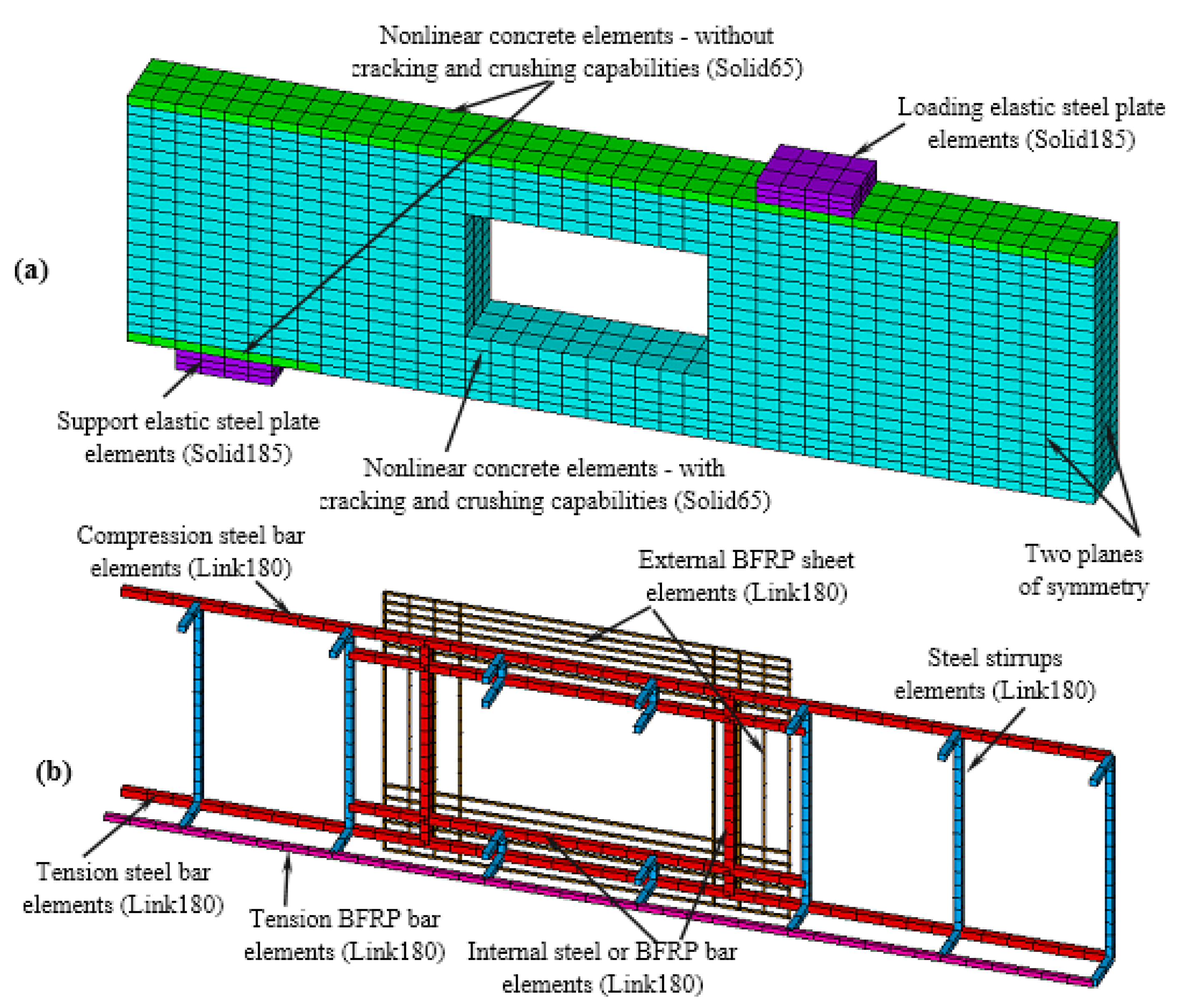
5.1. Element Types and Descriptions

ANSYS offers a library of elements of various capabilities, and by reviewing the literature studies, it could be emphasized that there are three main element types: namely, SOLID65, SOLID185, and LINK180 have been used in a wide range of nonlinear three-dimensional (3D) models on RC members to simulate the behavior of concrete and steel plates at support and loading locations, and steel and FRP reinforcements, respectively. The SOLID65 element is a 3D solid element defined by eight nodes, having three degrees of freedom at each node representing the translations in the nodal x, y, and z directions. This element is capable of simulating both the cracking and crushing of concrete. The definition of the SOLID185 element is quite similar to that of the SOLID65 element except for its inability to simulate cracking and crushing. The LINK180 structural bar element is a 3D two-node element with three degrees of freedom (translations in the three Cartesian directions). Moreover, the spring element (COMBIN39) of zero length was adopted to consider simulating the bonding behavior between the steel and BFRP LINK180 elements in the tension side of the beams. The steel and BFRP reinforcements in the longitudinal and transverse directions were adopted using the 3D structural element LINK180 bar element to simulate their behaviors. Also, the BFRP sheet that was externally bonded around the openings was adopted with the same structural element.

5.2. Material Modeling

A proper definition of different material behaviors is a key parameter in nonlinear structural modeling. Therefore, structural nonlinearity was considered by simulating the cracking of concrete in tension, the nonlinear behavior of concrete in compression, and the plastic behavior of steel and BFRP reinforcement. As shown in Figure 11a, the MacGregor model [41] was adopted to define the concrete nonlinear behavior in compression and tension. In both models, f c and ε c o are the maximum concrete compressive strength and the corresponding axial strain = 2 f c /Ec, respectively; ft is the ultimate tensile strength = 0.62( f c )0.5, and Ec is the modulus of elasticity of concrete. Moreover, a value of 0.2 was defined for the concrete Poisson’s ratio. Furthermore, proper values of 0.4 and 0.9 were defined for the open and closed shear coefficients, respectively. It is worth mentioning that the concrete of the beams at locations just below the loading plates and just above the supporting plates was simulated while neglecting the crushing capability in order to prevent convergence difficulties due to the stress concentrations at these locations. On the other hand, the elastic material property of the rigid steel plates at loading and supporting locations was simulated with a modulus of elasticity of 200 GPa and a Poisson’s ratio of 0.3. Finally, a bilinear elastoplastic material model with a strain-hardening ratio of 0.01 [42] was defined for the steel reinforcement, while a uniaxial elastic property was defined for the BFRP reinforcement. Figure 11b presents the material models of both the steel and BFRP bars.

5.3. Bond-Slip Modeling

By reviewing the numerical studies found in the literature, it was found that the majority of studies have ignored the bond slip of reinforcing bars, especially in SRC members. The results of other studies conducted on FSRC members, on the other hand, emphasized the importance of the inclusion of bond-slip behavior between the reinforcing bars and the surrounding concrete [38]. Therefore, the data of the authors’ studies [38,39] carried out to investigate the effect of various surface conditions on the bond-slip model of BFRP bars were adopted in the present study. The bond-slip model of BFRP bars having surface conditions similar to those of the one used in the experimental tests was employed here in the FE models, while the CEB-Code model [43] was adopted to simulate the bond-slip behavior of longitudinal steel bars. For more details regarding the bond-slip models of both steel and BFRP bars, refer to the authors’ published journal papers [38,39].

5.4. Boundary Conditions, Loading Applications, and Nonlinear Solution

Following the experimental test procedures, boundary conditions representing the cases of simply supported beams were adopted here by constraining the nodes of the edge supports in the vertical directions. As a result of the symmetry of all tested beams in both the longitudinal and transverse directions, only a quarter of the beams were modeled by applying symmetry boundary conditions at the mid-length and mid-width sections; i.e., the nodes in these sections were prevented from displacing in the perpendicular directions. The loading procedure was applied at the loading position via a displacement control technique in a stepwise increasing process, where the prediction of the sequential loading steps was controlled by adopting automatic time stepping, offered in the ANSYS solution. Newton–Raphson equilibrium iterations were adopted to check the convergence criteria at the end of each loading step.

6. Results, Analysis, Verification, and Discussion

Table 6 shows the relevant numerical and experimental results. For the cracking stage, the numerical cracking load and vertical deflection were compatible with the experimental load and vertical deflection by almost 91% to 117% and 96% to 104%, respectively. In the yielding stage, the numerical yielding load and vertical deflection were compatible with experimental load and vertical deflection by almost 100% to 104% and 87% to 105%, respectively. Therefore, in the peak stage, the numerical maximum load and vertical deflection were compatible with experimental load and vertical deflection by almost 94% to 110% and 96% to 109%, respectively. Therefore, the numerical model confirmed the relevant experimental results.
Figure 12 shows the relationship between the total load versus mid-span vertical de-flection for all tested beams. The numerical results curves have the same trend as the experimental curves. The curve was linear up to the first crack with higher elastic Young’s modulus, followed by a decrease in the line slope, which led to a decrease in the tangent Young’s modulus for BSF and BSFO-IS-EF beams until the end of the yielding stage. Moreover, the peak stage started, and crushing in concrete happened. Afterward, the beam failed due to the rupture of BFRP bars in the BSF beam, while the BSFO beam failed by shear due to the presence of the openings. On the other hand, the other opened beams did not reach the yielding stage due to strength loss in the shear zone. However, the concrete started to lose its strength (decreasing in the slope of the curve), which appeared significantly in the experimental and numerical curves until it reached the shear failure due to the presence of the openings.
Table 7 and Figure 13 show the relationship between load versus vertical deflection curves for the tested beams. The BSF solid beam showed a linear relationship up to the first cracking load of 30 kN, followed by a steel-yielding load of 69 kN. Afterward, concrete was crushed at the top fiber of the beam. Finally, the BFRP bars ruptured at the maximum load of 148.8 kN. The beam behavior was affected by the contribution of the FRP reinforcement and confirmed by the ratio between the maximum load to the yielding load of 5.43 times. That could be because of the FRP bar’s contribution to boosting the beam strength and post-yielding stage. Beyond the yielding stage, the FRP reinforcement contribution became significant. The post-yielding stiffness was clearly positively realized up to failure. At failure, excessive deep cracks and crushing appeared at the mid-top fiber of the beam, and the absorbed energy was larger than the other tested beams due to the failure of all resisting elements sequentially (yield of steel, crushing in concrete, and rupture of BFRP). Therefore, the beam achieved the optimum values for stiffness and ductility compared with the other opened beams. The BSFO beam showed a linear relationship between the total load and the vertical deflection curve up to the cracking load of 11.5 kN, and the first crack appeared around the opening corner. However, the crack distribution increased and propagated widely due to a lack of reinforcement around the opening corner. The maximum load was 37.7 kN. Consequently, the opening without internal reinforcement or external strengthening reduced the maximum load by 75%, in addition to changing the beam crack pattern to shear failure in the opening zone.
The BSFO-IS beam with internal steel-reinforced openings showed a linear behavior up to the cracking load of 9.3 kN (less than the BSFO beam). That means internal steel reinforcement about the beam opening did not resist any stresses until the first crack. Yield load was missing, and the maximum load was 61.1 kN. Also, the absorbed energy increased compared with the BSFO beam due to placing the internal steel reinforcement around the opening’s corner, leading to post-crack propagation. Therefore, the BSFO-IF beam reinforced with internal BFRP around the opening’s corners showed almost the same performance. The cracking and maximum loads were 10.0 kN and 60.2 kN, respectively (closer to those of the BSFO-IS beam). On the other hand, using the external BFRP sheet to strengthen the opening corners enhanced the performance of the BSFO-EF beam. Therefore, the cracking load reached 12.6 kN, and the maximum load was 66.5 kN. So, that means the beam gained more strength and absorbed more energy than beams with internal reinforcement, whether reinforced with steel or BFRP bars.
Enhancing the beam with steel bars around the beam opening and external BFRP sheet in the BSFO-IS-EF beam increased the structural performance compared to the BSFO-EF beam. The cracking, yield, and maximum loads were recorded at 15.0 kN, 65.6 kN, and 89.5 kN, respectively. The internal steel reinforcement and external BFRP sheet around the opening corner arrested the crack spread and post-crack propagation. Also, the absorbed energy increased more than in the other opened beams but decreased by 65% compared with the solid beam.

Crack Pattern and Failure Mode

The first flexural crack propagated at the tension fiber of the mid-span in the BSF beam and was followed by excessive cracks that appeared widely after the yielding of the steel bars, and the concrete top fiber was crushed, followed by the BFRP bar’s rupture. On the other hand, the BSFO beam failed due to the shear mode in the beam opening. That was confirmed by the appearance of the first cracks around the opening corner. Excessively, the crack was widened due to stress concentrations around the beam opening. The crack pattern demonstrated that a non-strengthened opened beam with inadequate reinforcement around the opening zone is brittle and fails early. Four hinges, one at the top and bottom chord ends, clearly make up the failure mechanism. On the other hand, the crack distribution decreased by reinforcing the opening’s corner internally. However, this reduction appeared significantly in the other tested beams. Furthermore, in the BSF-IS and BSF-IF beams, the crack width decreased compared with the BSFO beam, but finally, the beams failed in the shear mode. It is worth mentioning that the width of the deterioration area at the corners of the openings of this beam was much less than the extension distance of the reinforcing bars to the right and left of the openings, and this confirms the sufficiency of anchorage length used for these bars. The BSFO-EF beam arrested crack propagation and reduced crack distribution. This beam achieved desirable performance in crack control, and to improve crack control, the BSFO-IS-EF beam is highly recommended in this mission, as it prevents damage even after failure. Figure 14 shows the focused shear zone area for comparative experimental crack patterns of different beams. It is worth mentioning that the crack pattern for the numerical model was compatible with the experimental crack distribution. Figure 14 shows the experimental crack pattern for the tested beams. According to numerical analysis, Figure 15, Figure 16, Figure 17 and Figure 18 show the numerical crack pattern. It clearly appeared numerically that the first crack began from the opening corners due to stress concentration, and by increasing the applied load, excessive cracks propagated and spread around the beam opening until the shear failure. This failure was typical for all beams in the numerical model.

7. Extended Numerical Parametric Study

The numerical study extended to taking benefits of the created model from the finite elements program (ANSYS) [35]. This model saves time, cost, and effort. Therefore, it was necessary to expand the study to include other parameters, namely the effect of the BFRP reinforcement ratio around the beam openings (using diameters of 12, 16, and 18 mm) with the same number of experimental bars (four bars per side of the beam opening), in addition to studying the number of suitable BFRP sheets (using one, two, and three layers). After obtaining the maximum load in the previously studied cases, the optimal diameter and an optimum number of BFRP sheet layers were modeled, trying to reach the maximum load as the unopened hybrid reinforced beam. The following Table 8 outlines the results obtained.
It is noted from Figure 19 that the increase in the BFRP reinforcement area (increasing the BFRP bar diameter) does not enhance the maximum load of the tested beams with significant values. That is because increasing the reinforcement area around the opening corner decreases the stress inside BFRP bars, which leads to concrete crushing firstly. So, it is desirable to add BFRP reinforcement of diameter Φ10 to be more compatible in strength with concrete or use high-strength concrete in the case of larger diameters. The diameter of Φ10 performed with more ductility and stiffness because the maximum load reached higher mid-span vertical deflection. This behavior is more desirable to gain more absorbed energy.
It seems from Figure 20 that the increase in the BFRP sheet layers to two layers enhanced the maximum load of the opened beams with significant values. It is expected due to increasing the thickness of the resisting element (BFRP sheet), but after the second layer, there is no enhancement in the maximum load. It is worth mentioning that using two layers of BFRP sheet gives more absorbed energy than the other numbers of layers.
From the aforementioned results, BFRP of diameter Φ10, in addition to two layers of BFRP sheet, was chosen to combine its effect on the performance of the opened beam. It is noted from Figure 21 that the combined effect enhanced the maximum load compared to other opened beams. According to reinforced concrete design guidelines, the maximum concrete strain is 0.003, and the adjacent total load in the control beam is 119.0 kN (the onset crushing load). That means the combination of BFRP Φ10 and two layers of BFRP sheet achieved 78% of the total design load of the unopened beam (control).
The maximum load for unopened beams is more than that of the opened beams even though they are strengthened with internal BFRP reinforcement or external BFRP reinforcement sheet. Also, if the combined strengthening of internal BFRP reinforcement and external BFRP reinforcement sheet applied to the opened beam, it cannot restore a maximum load comparable to that of the unopened beam. That is due to the large opening that affects the beam strength in shear. The non-strengthened opened beam lost 70%. Therefore, increasing the diameters of BFRP bars from Φ10 to Φ18 enhanced the maximum load by 38% to 47%, respectively, compared with the non-strengthened opened beam. On the other hand, by increasing the number of BFRP sheet layers from one to two, the maximum load increased by 58%, and 67%, respectively, compared with the non-strengthened opened beam, but the maximum load in the case of three layers increased by 66% (less than that achieved with two layers). Combining the strengthening method with internal BFRP bars and external sheets enhanced the maximum load by 125% compared with the non-strengthened opened beam. Figure 22 shows the maximum numerical load for all beams.

8. Design Recommendations for Opened Hybrid Reinforced Beams

In this section, the relationship between the volumetric reinforcement ratio of the studied beam and the maximum load was investigated. Table 9 shows the added reinforcement volume to the opening volume ratio of the different opened beams. The calculated added reinforcement volume is based on the length and width of the opening (L = 250 mm, and W = 150 mm) and considers the full anchorage between concrete and additional reinforcement (internal or external). It appeared that by increasing the volumetric reinforcement ratio, the maximum load increased slightly for internal BFRP reinforcement. So, it is recommended to add 5% according to the findings per side for the opening to enhance the maximum load by 38% for a hybrid opened beam. Moreover, adding BFRP with two layers with a volumetric reinforcement ratio of 1% per side increases the maximum load by 67% compared with the non-strengthened opened beam. Despite the volumetric reinforcement ratio for the externally strengthened beam being the lowest value compared with internal BFRP bars, the beam achieved higher structural performance compared with the opened beam with internal reinforcement, whether reinforced with steel or BFRP bars. Hence, using the external BFRP sheets instead of internal reinforcement is highly recommended. Also, the BFRP sheets should be covered with a layer of cement mortar to protect them from environmental factors.

9. Conclusions

Based on the range of parameters that were studied experimentally and numerically, the following conclusions could be drawn:
  • The numerical model achieved identical experimental results with variations ranging from −9% to +17% and −6% to +10% for cracking and the maximum loads, respectively.
  • Hybrid reinforced solid beams invest the strength of all included materials such as steel bars and basalt fiber-reinforced polymer bars. Furthermore, the beam failed by steel yielding, and the concrete crushed, followed by the rupture of the basalt fiber-reinforced polymer bars. Hence, the steel reinforcement and the basalt fiber-reinforced polymer bars provide the beam strength in ascending strength level order. So, the solid beam gives the optimum solo desirable stiffness and deformability behaviors.
  • Using the external basalt fiber-reinforced polymer sheet to strengthen the opening’s corners enhanced the performance of the opened beam by 9% and 10% compared with opened beams with internal steel or basalt fiber-reinforced polymer bars, respectively, but by doubling the openings enhancement with internal steel bars and external basalt fiber reinforced polymer sheet, the maximum load increased by 137% compared with the unenhanced opened beam, and the maximum load increased by 46% and 49% in comparison to the opened beams reinforced internally with steel or basalt fiber-reinforced polymer bars, respectively. Further, the maximum load increased by 35% compared to the opened beam enhanced externally with the basalt fiber-reinforced polymer sheet only.
  • The absorbed energy improved significantly for the opened beam with internal steel bars and the external basalt fiber-reinforced polymer sheet by 191% compared with the unenhanced opened beam. Furthermore, the absorbed energy increased by 163% and 142% compared with the beams reinforced internally with steel or basalt fiber-reinforced polymer bars, respectively. Moreover, the maximum load increased by 185% concerning the opened beam enhanced externally with the basalt fiber-reinforced polymer sheet only.
  • Enhancing the opening’s corners with internal reinforcement reduced the crack propagation and posted the beam failure. Therefore, the opened beam strengthened externally with the basalt fiber-reinforced polymer sheet arrested the crack propagation and reduced crack distribution. Consequently, doubling the opening’s enhancement with internal steel bars and external basalt fiber-reinforced polymer sheets improved crack control and prevented beam damage even after failure. Also, using the external basalt fiber-reinforced polymer sheets instead of the internal reinforcement or doubling the enhancement with internal reinforcement and external strengthening with a basalt fiber-reinforced polymer sheet is highly recommended to enhance the maximum load and the absorbed energy.
  • Adding four basalt fiber-reinforced polymer reinforcements of diameter Φ10 per side is more compatible in strength with concrete and gives more ductility, absorbed energy, and stiffness in comparison to adding the same number of reinforcements but with different diameters. Furthermore, using two layers of basalt fiber-reinforced polymer external sheets gives more absorbed energy than the other numbers of layers. It is recommended to add a volumetric reinforcement ratio of 5% according to the findings per side for the opening to enhance the maximum load by 38% for a hybrid opened beam. Moreover, adding basalt fiber-reinforced polymer sheet in two layers with a volumetric reinforcement ratio of 1% per side increases the maximum load by 67% compared with the non-strengthened opened beam.

Author Contributions

Conceptualization, S.Y. and A.M.A.I.; methodology, S.Y. and A.M.A.I.; software, S.Y. and A.M.A.I.; validation, S.Y. and A.M.A.I.; formal analysis, S.Y. and A.M.A.I.; investigation, S.Y. and A.M.A.I.; practical, B.F.; data curation, S.Y. and A.M.A.I.; writing—original draft preparation, S.Y. and A.M.A.I.; writing—review and editing, S.Y. and A.M.A.I.; visualization, S.Y. and A.M.A.I.; supervision, S.Y. and A.M.A.I. All authors have read and agreed to the published version of the manuscript.

Funding

This research received no external funding.

Data Availability Statement

The data that support the findings of this study are available from the corresponding author upon reasonable request.

Conflicts of Interest

The authors declare no conflict of interest.

References

  1. Jianbing, Y.; Yufeng, X.; Saijie, L.; Zhiqiang, X. Experimental study on shear performance of basalt fiber concrete beams without web reinforcement. Case Stud. Constr. Mater. 2022, 17, e01602. [Google Scholar] [CrossRef]
  2. Biradar, S.V.; Injaganeri, S.S. Studies on Flexural Behaviour of Concrete Beams Reinforced with Basalt Rebars. IOP Conf. Ser. Mater. Sci. Eng. 2020, 1006, 012032. [Google Scholar] [CrossRef]
  3. Mhanna, H.H.; Alkhraisha, H.; Abed, F. FE modeling of concerte beams reinforced in flexure using BFRP bars. In Proceedings of the 2020 Advances in Science and Engineering Technology International Conferences (ASET), Dubai, United Arab Emirates, 4 February–9 April 2020; pp. 1–5. [Google Scholar] [CrossRef]
  4. Lapko, A.; Urbański, M. Experimental and theoretical analysis of deflections of concrete beams reinforced with basalt rebar. Archiv. Civ. Mech. Eng. 2015, 15, 223–230. [Google Scholar] [CrossRef]
  5. Li, Z.; Wan, S.; Ma, C.; Guo, X. Flexural behaviour of concrete-basalt FRC beams with steel bars under concentrated load. Structures 2022, 39, 237–252. [Google Scholar] [CrossRef]
  6. Krassowska, J.; Ramírez, C.P. Flexural Capacity of Concrete Beams with Basalt Fiber-Reinforced Polymer Bars and Stirrups. Materials 2022, 15, 8270. [Google Scholar] [CrossRef] [PubMed]
  7. Sun, S.; Guo, Y.; Gui, P.; Xing, L.; Mei, K. Flexural behaviour of steel–basalt fibre composite bar-reinforced concrete beams. Eng. Struct. 2023, 289, 116246. [Google Scholar] [CrossRef]
  8. Said, H.; Hassanean, M.; Hassanean, Y.; Ibrahim, A. Flexural Behavior of Concrete Box Girders Reinforced with Mixed Steel and Basalt Fiber-Reinforced Polymer Bars. JES J. Eng. Sci. 2023, 51, 223–241. [Google Scholar] [CrossRef]
  9. Su, C.; Wang, X.; Ding, L.; Liu, S.; Wu, Z. Flexural property and design method evaluation of BFRP and steel bars hybrid reinforced concrete beams. Struct. Concr. 2023, 24, 4942–4959. [Google Scholar] [CrossRef]
  10. Lu, C.H.; Li, H.; Xu, K.; Xuan, G.Y.; Abdullah, W. Experimental study of flexural behavior and serviceability of hybrid concrete beams reinforced by steel and G/BFRP bars. IOP Conf. Ser. Mater. Sci. Eng. 2020, 770, 012007. [Google Scholar] [CrossRef]
  11. Hussein, A.; Huang, H.; Okuno, Y.; Wu, Z. Experimental and numerical parametric study on flexural behavior of concrete beams reinforced with hybrid combinations of steel and BFRP bars. Compos. Struct. 2022, 302, 116230. [Google Scholar] [CrossRef]
  12. Elsanadedy, H.M.; Al-Salloum, Y.A.; Almusallam, T.H.; Alshenawy, A.O.; Abbas, H. Experimental and numerical study on FRP-upgraded RC beams with large rectangular web openings in shear zones. Constr. Build. Mater. 2019, 194, 322–343. [Google Scholar] [CrossRef]
  13. Pertiwi, D.; Komara, I.; Fristian, R. Design concept of reinforced concrete beams with large web Openings. ICATECH 2020 IOP Conf. Ser. Mater. Sci. Eng. 2021, 1010, 012039. [Google Scholar] [CrossRef]
  14. ACI CODE-318-19(22); Building Code Requirements for Structural Concrete and Commentary (Reapproved 2022). American Concrete Institute: Farmington Hills, MI, USA, 2022.
  15. Allam, S.M. Strengthening of RC beams with large openings in the shear zone. Alex. Eng. J. 2005, 44, 59–78. [Google Scholar]
  16. Wang, Y.D.; Yang, S.; Han, M.; Yang, X. Experimental study of section enlargement with reinforced concrete to increase shear capacity for damaged reinforced concrete beams. Appl. Mech. Mater. 2013, 256, 1148–1153. [Google Scholar] [CrossRef]
  17. Elkafrawy, M.; Khalil, A.; AlHamaydeh, M.; Hawileh, R.; Abuzaid, W. Enhancing the Shear Capacity of RC Beams with Web Openings in Shear Zones Using Pre-Stressed Fe-SMA Bars: Numerical Study. Buildings 2023, 13, 1505. [Google Scholar] [CrossRef]
  18. Torunbalci, N. Behaviour and Design of Large Rectangular Openings in Reinforced Concrete Beams. Archit. Sci. Rev. 2011, 45, 91–96. [Google Scholar] [CrossRef]
  19. Mondal, S.; Bandyapadhya, J.N.; Gautam, C.P. Strengthening and rehabilitation of reinforced concrete beams with Opening. Int. J. Civ. Struct. Eng. 2011, 2, 1. [Google Scholar]
  20. Chin, S.C.; Shafiq, N.; Nuruddin, M.F. Strengthening of RC Beams with Large Openings in Shear by CFRP Laminates: Experiment and 2D Nonlinear Finite Element Analysis. Res. J. Appl. Sci. Eng. Technol. 2012, 4, 1172–1180. [Google Scholar]
  21. Surya Sunder, S.; Babu, N.; Paulose, D. Experimental Study on Strengthening of Openings in R.C Beams using BFRP Fabric. Int. J. Innov. Res. Sci. Eng. Technol. 2016, 5, 8. [Google Scholar]
  22. Pillai, S.S.; Johny, A. Analytical Study on Shear Behavior of Reinforced Concrete Beam with Varying Shapes of Web Opening. Int. J. Eng. Res. Technol. (IJERT) 2018, 6, 1–4. [Google Scholar]
  23. Özkılıç, Y.O.; Aksoylu, C.; Hakeem, I.Y.; Özdöner, N.; Kalkan, İ.; Karalar, M.; Beskopylny, A.N. Shear and Bending Performances of Reinforced Concrete Beams with Different Sizes of Circular Openings. Buildings 2023, 13, 1989. [Google Scholar] [CrossRef]
  24. Jomaah, M.M.; Ghaidan, D.J. Energy Absorption Capacity of Layered Lightweight Reinforced Concrete Beams with Openings in Web. Civ. Eng. J. 2019, 5, 3. [Google Scholar] [CrossRef]
  25. ES:4756-1/2022; Egyptian Standards for Cement. Egyptian Organization for Standards & Quality: Cairo, Egypt, 2022.
  26. ES:1109/2021; Egyptian Standards for Natural Aggregate. Egyptian Organization for Standards & Quality: Cairo, Egypt, 2021.
  27. ES, 262-2021; Egyptian Standards for Steel Reinforcement. Egyptian Organization for Standards & Quality: Cairo, Egypt, 2021.
  28. ACI:440.3R-12; Guide Test Methods for Fiber-Reinforced Polymer (FRP) Composites for Reinforcing or Strengthening Concrete and Masonry Structures. American Concrete Institute Committee Report; American Concrete Institute Committee: Farmington Hills, MI, USA, 2012.
  29. ASTM D7205/D7205M-06; Standard Test Method for Tensile Properties of Fiber Reinforced Polymer Matrix Composite Bars. American Society for Testing and Materials: Conshohocken, PA, USA, 2016.
  30. BS: 8500:2019; British Standard for Concrete Mix Design. Concrete—Complementary British Standard to BS EN 206. British Standards Institution: London, UK, 2019.
  31. ASTM A615/A615M-04A; Standard Specification for Deformed and Plain Billet-Steel Bars for Concrete Reinforcement. American Society for Testing and Materials: Conshohocken, PA, USA, 2004.
  32. Qin, R.; Zhou, A.; Lau, D. Effect of reinforcement ratio on the flexural performance of hybrid FRP reinforced concrete beams. J. Compos. Part B 2017, 108, 200–209. [Google Scholar] [CrossRef]
  33. El Refai, A.; Abed, F.; Al-Rahmani, A. Structural performance and serviceability of concrete beams reinforced with hybrid (GFRP and steel) bars. J. Constr. Build. Mater. 2015, 96, 518–529. [Google Scholar] [CrossRef]
  34. Sikadur 330. Data Sheet. Available online: www.sika.com (accessed on 3 September 2023).
  35. ANSYS. A Finite Element Computer Software and User Manual for Nonlinear Structural Analysis; Release Version 15.0; ANSYS: Canonsburg, PA, USA, 2013. [Google Scholar]
  36. Arafa, M.A.I.; Hesham, M.D.; Yehia, A.H.; Omar, A.F.; Mustafa, M.A.I. Numerical study on the behavior and strength of concrete beam strengthening with fiber reinforced concrete jackets. Structures 2023, 50, 1557–1572. [Google Scholar] [CrossRef]
  37. Mustafa, S.A.A.; Hassan, H.A. Behavior of concrete beams reinforced with hybrid steel and FRP composites. HBRC J. 2018, 14, 300–308. [Google Scholar] [CrossRef]
  38. Ibrahim, A.M.; Fahmy, M.F.; Wu, Z. 3D finite element modeling of bond-controlled behavior of steel and basalt FRP-reinforced concrete square bridge columns under lateral loading. Compos. Struct. 2016, 143, 33–52. [Google Scholar] [CrossRef]
  39. Yehia, S.; Ibrahim, A.M.A.; Faihan, B. Experimental study on steel-FRP reinforced concrete beams with large rectangular openings. Int. J. Sci. Eng. Res. 2021, 12, 657–661. [Google Scholar]
  40. Hawileh, R.A.; El-Maaddawy, T.A.; Naser, M.Z. Nonlinear finite element modeling of concrete deep beams with openings strengthened with externally-bonded composites. Mater. Des. 2012, 42, 378–387. [Google Scholar] [CrossRef]
  41. MacGregor, J.G. Reinforced Concrete Mechanics and Design; Prentice-Hall Inc.: Englewood Cliffs, NJ, USA, 1992. [Google Scholar]
  42. Kachlakev, D.; Miller, T.; Yim, S. Finite Element Modeling of Reinforced Concrete Structures Strengthened with FRP Laminates; Final Report, SPR 316; Oregon Department of Transportation Research Group: Salem, OR, USA, 2001.
  43. CEB. CEB-FIP Model Code 90; CEB: London, UK, 1992. [Google Scholar]
Figure 1. BFRP sheet samples before and after tensile strength testing.
Buildings 13 02522 g001
Figure 2. Details of the (BSF) beam (units: mm).
Buildings 13 02522 g002
Figure 3. Details of the (BSFO) beam (units: mm).
Buildings 13 02522 g003
Figure 4. Details of the (BSFO-IS) beam (units: mm).
Buildings 13 02522 g004
Figure 5. Details of the (BSFO-IF) beam (units: mm).
Buildings 13 02522 g005
Figure 6. Details of the (BSFO-EF) beam (units: mm).
Buildings 13 02522 g006
Figure 7. Details of the (BSFO-IS-EF) beam (units: mm).
Buildings 13 02522 g007
Figure 8. Installing the BFRP sheet.
Buildings 13 02522 g008
Figure 9. Loading and test setup for the tested beams.
Buildings 13 02522 g009
Figure 10. 3 Dimensional FE model for a typical quarter of the tested beams: Concrete and steel plate solid elements (a) and reinforcing steel and BFRP bar and BFRP sheet elements (b).
Buildings 13 02522 g010
Figure 11. Constitutive material models of concrete in compression and tension (a) and steel and BFRP bars (b).
Buildings 13 02522 g011
Figure 12. The total load versus the vertical deflection in the numerical and experimental results for the tested beams.
Buildings 13 02522 g012
Figure 13. The total load versus the vertical deflection for tested beams.
Buildings 13 02522 g013
Figure 14. Crack pattern for tested beams.
Buildings 13 02522 g014
Figure 15. Developed status of a quarter FE model of the beam BSFO: first cracking pattern, cracking and crushing patterns at failure, concrete strain contour at failure.
Buildings 13 02522 g015
Figure 16. Status of BSFO-IS: concrete strain contour at failure of FE model, and cracking and crushing patterns at failure of FE model.
Buildings 13 02522 g016
Figure 17. Status of BSFO-EF: concrete strain contour at failure of FE model, and cracking and crushing patterns at failure of FE model.
Buildings 13 02522 g017
Figure 18. Status of BSFO-IS-EF: concrete strain contour at failure of FE model, and cracking and crushing patterns at failure of FE model.
Buildings 13 02522 g018
Figure 19. The relationship between the maximum load and mid-span vertical deflection for numerical beams with different BFRP bar diameters.
Buildings 13 02522 g019
Figure 20. The relationship between the maximum load and mid-span vertical deflection for numerical beams with different numbers of BFRP sheet layers.
Buildings 13 02522 g020
Figure 21. The relationship between the total load and mid-span vertical deflection for numerical beams (BSF, BSFO, and BSFO-IFΦ10-EF2L’s).
Buildings 13 02522 g021
Figure 22. The numerical maximum load for all beams.
Buildings 13 02522 g022
Table 5. Details of the tested specimens.
Beam CodeBottom BarsCompression Steel BarsSteel
Stirrups
Opening Enhancement
SteelBFRPInternal
Steel Bars
Internal BFRP BarsExternal BFRP Sheet
BSF2Φ101Φ102Φ10φ8@150 mm---
BSFO---
BSFO-IS2Φ10--
BSFO-IF-2Φ10-
BSFO-EF--75 mm width
BSFO-IS-EF2Φ10-75 mm width
Table 6. Experimental and numerical structural performance characteristic values of the tested beams.
Beam
Code
Cracking StageYielding StagePeak StageFailure Mode
Exp.Num.Exp.Num.Exp.Num.
Pcr
(kN)
cr
(mm)
Pcr
(kN)
cr
(mm)
Py
(kN)
y
(mm)
Py
(kN)
y
(mm)
Pm
(kN)
m
(mm)
Pm
(kN)
m
(mm)
BSF30.01.1227.41.07693.869.34.0148.836.5140.135.0SY, CC, and FR
BSFO11.51.7610.51.73----37.712.341.512.6SF at opening
BSFO-IS9.31.2710.91.31----61.110.861.511.1SF at opening
BSFO-IF10.01.3910.81.40----60.213.858.015.0SF at opening
BSFO-EF12.61.4314.71.49----66.511.265.412.0SF at opening
BSFO-IS-EF15.01.5214.11.4765.67.768.36.789.520.287.221.8SF at opening
Where: SY is the steel yielding, CC is the concrete crushing, FR is the rupture of BFRP bar, and SF is the shear failure.
Table 7. Stiffness and deformability indices for the tested beams.
Beam CodeStiffness (kN/mm)Deformability
Initial Stiffness
Py/Δy
Pre-Cracking Stiffness
Pcr/Δcr
Post-Cracking
Stiffness
(Py–Pcr)/(Δy–Δcr)
Post-Yielding
Stiffness
(Pu–Py)/(Δu–Δy)
Energy
(kN.mm)
Ductility
Δu/Δy
BSF18.1626.7914.552.4440289.61
BSFO -6.53- - 484-
BSFO-IS- 7.32 -- 535-
BSFO-IF -7.19- - 581-
BSFO-EF -8.81 - -762 -
BSFO-IS-EF8.529.878.191.9114072.62
Table 8. Results for extended numerical parameters.
Beam CodePm
(kN)
m
(mm)
Parameter
BSF140.135.0Control
BSFO41.512.6Without strengthening
BSFO-IF-Φ1057.215.80Effect of using Φ10
BSFO-IF-Φ1258.012.8Effect of using Φ12
BSFO-IF-Φ1660.88.7Effect of using Φ16
BSFO-IF-Φ1861.08.7Effect of using Φ18
BSFO-EF-1L65.412.0Effect of one layer of BFRP sheet
BSFO-EF-2L’s69.412.0Effect of two layers of BFRP sheet
BSFO-EF-3L’s68.910.9Effect of three layers of BFRP sheet
BSFO-IFΦ10-EF2L’s93.424.3Effect of using Φ10 and two layers of BFRP sheet
Table 9. Test results for the extended parameters.
Beam CodePm
(kN)
Added
Internal BFRP
Reinforcement
(mm2)/Side
Added
External BFRP Strengthening Sheet
(mm2)
Opening
Volume
(Concrete)
(mm3)
Added
Reinforcement
Volume
(mm3)
(μ) Vol.
(%)
/Side
BSFO41.5--5,625,000--
BSFO-IF-Φ1057.2314.16-5,625,000251,3284.47
BSFO-IF-Φ1258.0452.39-5,625,000361,9126.43
BSFO-IF-Φ1660.8804.25-5,625,000643,40011.44
BSFO-IF-Φ1861.01017.88-5,625,000814,30414.48
BSFO-EF-1L65.4-33.35,625,00026,6400.47
BSFO-EF-2L’s69.4-66.65,625,00053,2800.95
BSFO-EF-3L’s68.9-99.95,625,00079,9201.42
Disclaimer/Publisher’s Note: The statements, opinions and data contained in all publications are solely those of the individual author(s) and contributor(s) and not of MDPI and/or the editor(s). MDPI and/or the editor(s) disclaim responsibility for any injury to people or property resulting from any ideas, methods, instructions or products referred to in the content.

