Article

Unbonded Pre-Tensioned CF-Laminates Mechanically Anchored to HSC Beams as a Sustainable Repair Solution for Detachment of Bonded CF-Laminates

by
Mohamed A. El Zareef
1,2,
Sabiha Barour
3,
Mosbeh R. Kaloop
4,5,6,* and
Waleed E. El-Demerdash
7
1
Civil Engineering Department, College of Engineering and Islamic Architecture, Umm Al-Qura University, Makkah 24381, Saudi Arabia
2
Structural Engineering Department, Faculty of Engineering, Mansoura University, Mansoura 35516, Egypt
3
Civil Engineering Department, Université des Frères Mentouri, Constantine 25017, Algeria
4
Department of Civil and Environmental Engineering, Incheon National University, Incheon 22012, Republic of Korea
5
Public Works Engineering Department, Mansoura University, Mansoura 35516, Egypt
6
Digital InnoCent Ltd., London WC2A 2JR, UK
7
Civil Engineering Department, Misr Higher Institute for Engineering and Technology, Mansoura 7651012, Egypt
*
Author to whom correspondence should be addressed.
Buildings 2023, 13(10), 2528; https://doi.org/10.3390/buildings13102528
Submission received: 16 September 2023 / Revised: 1 October 2023 / Accepted: 3 October 2023 / Published: 6 October 2023
(This article belongs to the Section Building Structures)

Abstract

:
The present article outlines a Finite Element Model (FEM) that was created and validated by comparing it to prior experimental investigations to estimate the flexural performance of HSC beams strengthened with exterior bonded, unbonded, and unbonded pre-tensioned Carbon Fibre Reinforced Polymer (CFRP) sheets in several patterns. Nonlinear analysis was performed on three-point-loaded beams using ANSYS software, incorporating the constitutive characteristics of various components (concrete, CFRP, and steel). The comparison of FE-models and experimental data, namely for load-deflection curves, crack patterns, and failure modes, revealed that the developed numerical FE-models and experimental outcomes are in good accord. There has been numerous prior research on the behavior of beams strengthened with externally bonded CFRP sheets, but few on those reinforced with externally unbonded CFRP laminates, and even fewer on HSC beams reinforced with externally unbonded pre-tensioned CFRP laminates. Therefore, the major contribution of this article is to investigate the flexural behavior of HSC beams strengthened utilizing externally unbonded pre-tensioned CFRP laminates. The analysis revealed that the bending performance of RC-beams strengthened using external unbonded pre-tensioned CFRP-laminates is quite similar to that of bonded CFRP-strengthened beams, indicating a high potential for tackling the durability issues caused by detachment of bonded CFRP-strips in such structural elements. The existence of a fully wrapped CF sheet forced the beam to develop diagonal shear cracks in the region between the wrapped CF sheet and beam supports while also enhancing the flexural cracked zone at mid-span to change from smeared to discrete fractures. The flexural fractures spread over a deeper and wider area of the beam as a result of the incorporation of a half-wrap CF laminate. Externally unbonded CFRP-sheets pre-tensioned with 45% of the CFRP ultimate strength utilizing various patterns (straight and U-wrap) performed similarly to bonded CFRP-sheets, with a slight boost in load capacity of around 4.5% and notable reduces in deflection ranging from 9.7% to 16.24%. Using exterior unbonded CFRP laminates to strengthen RC-beams resulted in a flexural capacity increase ranging from 22.3% for NC beams to 71.6% for HSC beams.

1. Introduction

1.1. Behaviour of Strengthened RC Beams Using Exterior Bonded-CFRP

The effectiveness of employing Fiber Reinforced Polymer (FRP) to boost the flexural strength of RC beams has been demonstrated in a number of experimental studies. The structural integrity of concrete structures reinforced with conventional steel reinforcement deteriorates as a result of their exposure to harsh environmental conditions such as high humidity, temperatures, and chlorides in maritime environments. One of the most significant alternatives for rehabilitating these buildings is to strengthen the deteriorated concrete elements using FRP composites, which is a durable material. Because of their lightweight, superior tensile-strength, fatigue strength, and corrosion resistance, comparable to traditional steel reinforcement, fiber-reinforced polymers have substantial prospective as replacements for steel in concrete structures, bridge cables, subterranean oil production, and marine engineering [1,2,3]. As described by Siddika et al. [4] and Shomali et al. [5], structures made of FRP-materials have greater ductility and strength. It can also lessen deflection and increase the final load (Su et al. [6] and Zhou et al. [7]).
A number of investigations have been performed on RC-beams that were externally strengthened with FRP and subjected to bending and shear stresses. According to Zhang et al. [8], Wakjira et al. [9], Zeng et al. [10], Hawileh et al. [11], and Wakjira et al. [12], the strength of strengthened RC-beams can be enhanced depending on several factors such as compression capacity of concrete, FRP and steel mechanical characteristics, steel reinforcement ratio, and FRP ratio.
You et al. [13] carried out experimental research on eight small-scale and two large-scale RC-beams strengthened with pre-stressed CFRP strips, and suggested that a pre-stressing technique enables the maximum capability of the CFRP sheets to be utilized. The major aspect was the amount of prestressing used, which varied from 20% to 70% of the CFRP sheet’s tensile-strength. The findings demonstrated that as the pre-stressing stress raised, the RC beams strengthened with pre-stressed CFRP sheets had greater first crack-load, steel yielding, and tested actual moment. Pitek et al. [14] designed a mechanical metal anchoring system for use in active CFRP bending strengthening methods for RC elements through a series of experiments. The designed anchoring had an ultimate tensile load of 185 kN, which was enough to support CFRP laminates. A finite element software was used by Kadhim et al. [15] to investigate the bending performance of RC beams strengthened with pre-stressed CFRP plates. The impact of pre-stressed CFRP plate positions, breadth, and thickness was investigated using parametric analysis. According to the study, using the pre-stressed CFRP strips on the margins boosted load capacity by around 11% over using it in the center of the RC beams. Pitek and Siwowski [16] tested five RC beams that were strengthened using passively CF sheets, without and with mechanical anchors, as well as using sheets tensioned by a pre-stressing technique at different pre-stressing rates varying from 30 to 50% of the CFRP tensile capacity. According to the findings, raising the pre-stressing degree of the beams has a significantly favorable impact on the response of strengthened RC beams. For a while, it had no impact on the beams’ maximum load capacity. Deng et al. [17] assessed the durability of rusted anchorage used in the pre-stressing of CFRP strips. Clamp anchorage and wedge anchorage were utilized to pre-stress CFRP strips, which were subsequently exposed to a corrosive environment using a galvanostatic accelerator followed by tensile testing. After 144 h of surface erosion, the wedge anchor had a pre-stress retention of 9.0% and an anchoring effectiveness of 100%. As a result, the wedge anchorage outperformed the clamp anchorage.
Kachlakeva et al. 2000 [18] studied the performance of strengthened RC beams using different shapes of CFRP and Glass-Fibre-Reinforced-Polymer (GFRP) to imitate the retrofitting of an actual concrete beam. When the beams were strengthened in both bending using CFRP and shear utilizing GFRP, the static capacity increased by 150% when compared to unstrengthened sections.
Adhikary et al. [19] researched the shear strengthening of RC beams utilizing exterior bonded FRP strips. Four distinct models were examined for evaluating the involvement of CFRP strips in the beams’ shear strength. The research looked at how lengthening the size of the strip on the outer layer of the beam may postpone or eliminate strip spalling. The types of fibers, wrapping patterns, and length of bonded anchoring were all test parameters. The trials demonstrated that FRP with bonded anchoring was significantly efficient compared to the U-wrapped approach. Expanding the strips on the outer layer of the beam reduced interface bond stresses while increasing FRP strain at failure. The study concluded that the shear strength of RC-beams strengthened with exterior bonded CFRP and AFRP increased by 123% and 118%, respectively.
Sing et al. [20] researched and tested a long RC beam strengthened with different patterns of GFRP-laminates. The tested beams have been categorized into two groups depending on the position of the load, and two-point loads were located at 500 mm from the beam’s midpoint in the first group and 200 mm from the beam’s center in the second group. The beams were strengthened using one, two, and three sheets of 2.5 m length GFRP strips, respectively. The others have been strengthened using one sheet of GFRP strips at 2.2 and 1.9 m lengths. The results of the tests revealed that such a bonding method might boost both the stiffness and bending capacity of the RC-beams. The researchers observed that bonding the GFRP strips increases the flexural capacity of the beams by 18–46%. Improvement in beam stiffness is visible up to 24%.
Pannirselvam et al. [21] experimentally analyzed RC beams strengthened with GFRP laminates on their soffits. The tested beams were examined using three various reinforcement ratios, and two kinds of GFRP each had a different thickness. The findings showed that the RC-beams strengthened using GFRP strips exhibited improved behavior. The increases in the first fracture load were 88.89% and 100%, while the raising in deformation ductility was noted to be 56.01% and 64.69% for GFRP-laminates having 3- and 5 mm thicknesses, respectively.
Several studies [22,23,24,25,26,27,28] investigated the impact of shear stirrups on RC-beams strengthened utilizing various FRP strip configurations. In comparison to the referenced beam, the laminated beams have a larger overall flexural strength and significantly improved ductility.
Dong et al. [29] looked into the performance of reinforced concrete elements with exterior laminates of carbon and glass FRP. The observed findings show that employing exterior bonded carbon or glass FRP strips on the lower and/or side surfaces of the beams can dramatically increase both their bending and bending-shear strength capability. The total moment strength of the CFRP-reinforced beams increases by 41% to 125% compared to the referenced beam, while the shear strength of the glass and carbon FRP-reinforced beams increases by 31% and 74%, respectively.
Based on the previous literature, there was extensive experimental data on the utilization of externally bonded CFRP sheets in strengthening RC-beams based on earlier publications. This data may be used in future studies by employing a machine learning approach [30] as an emerging technology to accurately estimate the flexural and shear capacity of RC-beams strengthened with externally bonded CFRP laminates.

1.2. Applications of Finite Element in the Analysis of FRP RC-Members

In recent years, Finite Element Analysis (FEA) was utilized to assess the general response of the buildings. Utilization of quantitative FE simulations improves comprehension of the behavior and more affordable parametric studies. Previous research [31,32,33,34,35,36,37,38,39] concluded that the fracture analysis of the slabs and beams could be correctly predicted using the finite element programs.
Dahmani et al. [40] investigated the advantages of numerical simulation over experimental testing, as well as the application of the ANSYS program for modeling and fracture pattern estimation in RC-beams. The overall load-deformation response produced was in good accord with the analysis’s results.
Sasmal et al. [41] focused on a numerical analysis of the performance of flexural strengthening using FRP attached to RC-beams utilizing ANSYS nonlinear finite element analysis software. SOLID-65, LINK-8, SHELL-41, and SOLID-45 have been utilized to represent concrete material, steel bars, FRP, and epoxy matrix, respectively. The numerical findings stated that as the fracture advances, the deformation in the FRP-laminated RC beams improved significantly.
Banu et al. [42] studied the impact of FRP material as an exterior bonded layer on the load bearing capability of two-way reinforced concrete slabs using ANSYS software. They employed the components SOLID65 and SOLID45 to simulate the 3D concrete beams and thick shells, respectively. Harihar and Kulkarni [43] also employed the NLFE ANSYS program to model the performance of RC beams strengthened using CFRP laminates. The findings were consistent with previously reported test outcomes.
Gopinath et al. [44] conducted a numerical analysis to investigate the performance of basalt-strengthened RC beams. The load-deflection charts from the numerical research match well with the experimental outcomes. Atea [45] utilized the ANSYS software to model the flexural performance of four RC-beams made up of varying-thickness steel plates. To provide an efficient link between the concrete element and the steel plates, shear connectors were used. The improvement in ultimate strength for plated beams over unplated beams was 73%, 86%, and 161% for steel plate thicknesses of 2-, 3-, and 5-mm, respectively. Concrete strains, fracture widths, and the number of cracks reduced as steel plate thickness increased.
Barour and Zergua [46], and Barour et al. [37] utilized the FE modeling to explore the shear region behavior of RC-beams externally strengthened using FRP strips. The NLFE ANSYS program produced findings that were in alignment with prior literature experimental data.
Based on the prior literature, the behavior of RC beams strengthened with externally bonded CFRP laminates has been extensively studied in previous decades, but the beams that were externally strengthened using unbonded CFRP laminates have received less attention, and even far less attention for HSC beams strengthened with externally unbonded pre-tensioned CFRP laminates. Therefore, this paper’s main contribution is to investigate the flexural performance of HSC beams that have been strengthened using externally unbonded pre-tensioned CFRP laminates.
In this paper, a three-point bending analysis was performed on RC beams that were strengthened using exterior bonded and unbonded FRP laminates. Due to durability issues associated with the spalling of exterior bonded CFRP strips, the response of RC beams with unbonded pre-tensioned CFRP laminates mechanically anchored at both ends of the beam is explored. The acquired FEA results for bonded CFRP strips are compared to those published in a prior experimental study by Akram et al. [47]. The beams were modeled using ANSYS software and a nonlinear static analysis with monotonic load steps. To represent the concrete, the composite layer of CFRP (bonded and unbonded), and the steel rebars, the SOLID-65, SHELL-181, and LINK-180 components were utilized, in that order.

2. Development of Finite Element Model

2.1. Geometry and Description of the Tested Specimens

The generated FE models for the externally bonded CFRP laminates simulate the tested samples in the experimental study of Akram et al. [47], in which the beams were 1200 mm span, 75 mm wide, and 150 mm height. Figure 1 depicts the geometries, steel bars detailing, and the description of the tested samples.

2.2. Development of the Finite Element Models

The FEMs of the tested specimens are generated utilizing the ANSYS software. After several tries to find the ideal mesh size that provides results that are somewhat similar to experimental data, the 3D mesh dimensions are assumed to be 25 × 25 × 25 mm. Figure 2 depicts the geometry of the FEM with different materials. To handle nonlinear problems, ANSYS adopts the “Newton–Raphson” method. In this manner, the load is broken down into a succession of load intervals. Load levels have the potential to be applied over a number of load intervals. Preceding each solution, the Newton–Raphson technique analyzes the out-of-balance load vector, which is the amount of variance between the restored loads (the loads equivalent to the member stresses) and the applied loads. The system utilizes the out-of-balance loads to generate a linear solution and verifies for convergence. If none of the convergence requirements are met, the out-of-balance load vector is evaluated again, the stiffness matrix is modified, and an iterative solution is generated. This iterative technique can describe the collapse progression for composite structures [48]. The next sections present the FEM elements and characteristics of various materials such as concrete, steel bars, loading plates, and CFRP laminates.

2.2.1. Concrete

The concrete material is represented by the SOLID65 element. Figure 3 demonstrates that the SOLID65 element comprises eight nodes, each with three translational Degrees-Of-Freedom (DOF) in the X, Y, and Z directions. The element could simulate the nonlinear concrete behavior in tension and compression zones [49,50,51].
The characteristics of concrete material are obtained based on experimental tests conducted by Akram et al. [47]. The cylinder’s 28-day concrete compression-strength is 21 MPa, and the Poisson’s ratio is 0.2. Table 1 shows the specifics of the relevant input data for concrete characteristics in ANSYS software.
The different concrete material properities that must be input into the NLFE ANSYS software to imitate the non-linear response of concrete incorporate isotropic parameters such as modulus of elasticity, uniaxial compression capacity, uniaxial tension, Poisson’s ratio, and two requested shear transfer factors represent an open crack βt and a closed crack βc. These factors range from zero for smoothed cracks to one for roughened cracks.

2.2.2. Steel Reinforcement

The LINK-180 element, shown in Figure 4, is utilized to imitate the longitudinal bars. Every node has three DOFs: nodal X, Y, and Z translations. All of the following properties are supported: plasticity, creep, rotation, high deformations, and large strains.
Steel bars are accounted to have an elastic-perfect-plastic behavior with strain-hardening and the same tensile and compression performances [49]. As stated in Table 2, the modulus of elasticity (EX) is specified, and the Poisson’s ratio (PRXY) is presumed to be 0.3, as specified in the experimental work of Akram et al. [47].

2.2.3. Loads and Bearing Steel Plates

As demonstrated in Figure 5, the SOLID-185 element is utilized to depict the loaded and bearing steel plates. SOLID-185 is made up of eight nodes, each with three DOFs. Displacements are in the X, Y, and Z nodal axes. SOLID-185 exhibits plasticity, hyper-elasticity, constraint stiffness, creep, significant deflections, and large strain features [49].
Steel plates’ material characteristics include modulus of elasticity and Poisson’s ratio, which are 2 × 10⁵ MPa and 0.3, respectively. The SOLID-185 element implies the use of an elastic linear isotropic material.

2.2.4. Carbon Fiber Reinforced Polymer (CFRP) Sheets

The CFRP laminates are simulated as anisotropic material utilizing the SHELL-181 element (Figure 6). It is a four node element having six DOFs at each node; displacements in the X, Y, and Z axes; and rotations about the X, Y, and Z axes. SHELL-181 is proper for linear- and large-rotation applications, as well as nonlinear applications with large strains [49].
The material characteristics adopted in the imitation of CFRP wraps are tensile strength, elasticity modulus, and shear modulus. The layer thickness of CFRP sheets equals 0.12 mm. Table 3 depicts the properties of CFRP materials.

3. Validation of the Proposed Finite Element Model

3.1. Comparison of the Load-Deflection Curves for Different Beams

To validate the FEMs utilized in the current research, a load-deflection comparison is made between the experimentally tested RC-beams strengthened with various patterns of exterior bonded CFRP laminates by Akram et al. [47] and the numerically simulated model created with ANSYS software. The load-deflection relationships acquired from tested samples and generated by FEMs are shown in Figure 7.
As demonstrated in Figure 7, the FEA results for ultimate load, load-deflection, and failure mode are generally well correlated with the outcomes of tested specimens. The experimental load-carrying capacity of RC-beams strengthened with different patterns of external bonded CFRP sheets (Method-1, 2, and 3) improved by 41% to 86% over the referenced beam, while the load capacity obtained from FEMs improved by 37% to 81% in comparison to the FE referenced beam. The greatest improvement in flexural strength was obtained when the RC-beam was strengthened using exterior bonded CFRP of method-2. The minor variations between the generated FEMs and the findings of tested samples might be related to the discrepancy between the experimental real-bond behavior and the FE perfect-bond of steel reinforcement with the surrounding material. Table 4 depicts the laboratory and FEMs findings for the control and RC-beams externally strengthened using different patterns of CFRP laminates. As presented in Table 4, the differences between the tested and FEM failure loads are between 0.2% and 7.67%, whereas the discrepancies between the experimentally observed at mid-span deflection and that derived from the FEM are between 6.76% and 11.71% for the referenced and all strengthened RC beams. In general, the FEM’s values are in good agreement with the experimental data, with the correlation coefficients (R) ranging between 0.870 and 0.983 for all tested and FE-modeled beams.

3.2. Crack Distribution and Failure Modes

The output findings of the FE-models outperform laboratory testing in various features. In the experiment, the Linear Variable Differential Transformer (LVDT) and finite strain gauges are utilized to appraise the output values at a specific place within the concrete members, allowing only an estimate of the outcomes at those locations, while the analytical FEMs offer extensive outcomes throughout the structural member at every load increment up to the collapse phase. The ANSYS program, for example, reports the fracture progression at each loading phase. Figure 8 displays the evolution of a typical ANSYS beam crack pattern at various applied loading phases.
Figure 9, Figure 10 and Figure 11 depict how cracks propagate in the FEMs for controlled and strengthened RC-beams from the phase of the first fracture to the crack pattern at the failure state. Flexural cracks were initiated in tension zone at the center of the beams and expanded as the applied force raised, resulting in flexural-shear cracks. This fracture behavior conforms to the experimental crack pattern encountered by Akram et al. [47].
The bending cracks were initiated at the bottom zone of the beam’s center under the first crack loads, as shown in Figure 9, Figure 10 and Figure 11. These early fractures are known as smeared cracks since they exhibit smaller spread areas and greater first crack loads in the cases of fully and half-wrapped CF laminates (Figure 10 and Figure 11, respectively) than those in the cases of control and straight CF laminates (Figure 9 and Figure 12, respectively). The presence of a fully wrapped CF sheet in the condition of Method 1 (Figure 10) enhanced the flexural cracked zone at the mid-span to be converted from smeared to discrete cracks while simultaneously pushing the beam to have diagonal shear cracks in the zone between the wrapped CF sheet and beam supports. In the case of Method 2, the presence of a half-wrap CF sheet drove the flexural fractures to expand over a deeper and broader area of the beam, as illustrated in Figure 11. These crack responses in Methods 1 and 2 may elucidate why the load capacity of fully wrapped CF sheet (Method 1) was lower than that of half-wrapped CF sheet (Method 2), which was similarly interpreted through the experimental results conducted by Akram et al. [47].

4. Parametric Study

Based on the validation of the generated ANSYS FEM for RC beams with various patterns of externally bonded CFRP laminates mentioned in the preceding sections, the verified FE models were utilized for further analysis and parametric study. Due to technical and durability issues that resulted in the detachment of externally bonded CFRP sheets, resulting in an abrupt decrease in the member’s flexural strength, the effect of increasing the contact surface between CFRP laminates and the beam’s exterior surface, mechanically anchored unbonded external CFRP strips, pre-tensioned unbonded external CFRP laminates, and concrete grades on the moment capacity of strengthened RC-beams have been investigated. The investigation’s results will be presented in the subsections that follow.

4.1. Effect of Contact Area between CFRP Laminates and Beam

To maximize the contact surface between the CFRP sheets and the bottom side of the beam, three varied patterns of externally bonded CFRP sheets (W25, W50, and W75) with the same cross-sectional area but various thicknesses and widths are analyzed. The dimensions of these three different patterns are (25 × 0.3) mm, (50 × 0.15) mm, and (75 × 0.1) mm. Figure 13 depicts the layout and dimensions of various strengthened RC beams with varying patterns of CFRP sheets.
Figure 14 depicts the load–deflection relationships and normal stresses derived from the FEMs for beams strengthened with three distinct patterns of CFRP laminates (W25, W50, and W75). As illustrated in Figure 14, the three load–deflection curves of the three beams were quite similar, with the largest difference between the ultimate load capacities of the three beams being 4.66% and the maximum difference between the maximum deflections of the three beams being 4.25%. This shows that raising the contact surface between the CFRP sheets and concrete may be one option to solve the durability issues regarding the splitting of CFRP laminates. Despite that solution, the risk of an abrupt drop in the ultimate load of the strengthened beam with exterior bonded CFRP laminates remains possible, depending on the surrounding thermal condition and the quality of the cohesion hazard materials utilized to stick the CFRP sheets to the beam’s surface. Therefore, the following section proposed another radically unique solution for this durability problem, utilizing externally unbonded CFRP sheets with and without pre-tensioned forces. The externally unbonded CFRP sheets are mechanically anchored at the ends of the tension side of the beams.

4.2. Effect of External Pre-Tensioned Unbonded Straight CFRP Sheets

The degradation of the adhesive hazard material over time was observed in several cases of strengthened beams utilizing exterior bonded CFRP strips. This deterioration in the adhesive material that caused the detachment of CFRP sheets may be attributed to variations in the thermal expansion coefficients of concrete, adhesive materials, and CFRP sheets, as well as the quality of adhesive material and the differential strains in CFRP sheets and the surrounding concrete layer. According to field observations, the detachment of CFRP sheets occurs abruptly, resulting in a sudden loss in the beam loading capacity, which may result in a catastrophic collapse.
As a solution to this issue, the current study proposes the use of external unbonded CFRP sheets that are mechanically fastened at the ends of the tension side of the strengthened beam. To improve the ultimate load and deflection of the strengthened beams, the exterior unbonded CFRP sheets were initially tensioned with varied degrees of pre-tension stresses as a ratio of CFRP ultimate stress (fucf). These various levels of pre-tension forces in CFRP sheets were determined to generate controlled camber with no cracks in the compression zone of the beam when just the beam’s own weight was applied. Figure 15 depicts the FE configurations of the strengthened RC beams utilizing 75 × 0.15 mm bonded and unbonded CFRP straight sheets with and without pre-tension forces.
Figure 16 presents the load–deflection relations obtained from the FEMs for strengthened beams using external CFRP straight laminates. The CFRP laminates have adhered to the concrete surface (B75), unbonded without pre-tension stress (U75 without pre-T), unbonded with pre-tension stress of 0.35 fucf (U75 with pre-T 35%), unbonded with pre-tension stress of 0.45 fucf (U75 with pre-T 45%), and unbonded with pre-tension stress of 0.65 fucf (U75 with pre-T 65%). The response of the strengthened beam using unbonded CFRP straight strips (U75 without pre-T) differs from that of the strengthened beam with bonded CFRP straight laminates (B75). The ultimate load of the beam (U75 without pre-T) is lowered by 17.6% when compared to the beam (B75). To enhance the flexural strength of the unbonded strengthened beam, pre-tension forces were applied to CFRP sheets with varied ratios of 35%, 45%, and 65% of fucf. The initial tension forces were estimated to control the camber of the beam while keeping tensile stresses in the compressive side of the beam below the concrete modulus of rupture. As depicted in Figure 17, the detected maximum camber was around 0.4 mm and the ultimate tensile stress in the compression side of the beam was 1.64 Mpa, utilizing only the self-weight of the beam and the maximum pre-tension force of 0.65 fucf. As shown in Figure 16, the case of (U75 with pre-T 45%) was comparable to the case of (B75), with a minor improvement in load capacity of 1.57% and a 9.7% reduction in deflection. These modest discrepancies are regarded within the permitted tolerances, with which the behavior of externally bonded (B75) and unbonded strengthened RC beams utilizing pre-tensioned CFRP straight sheets (U75 with pre-T 45%) may be deemed equivalent.

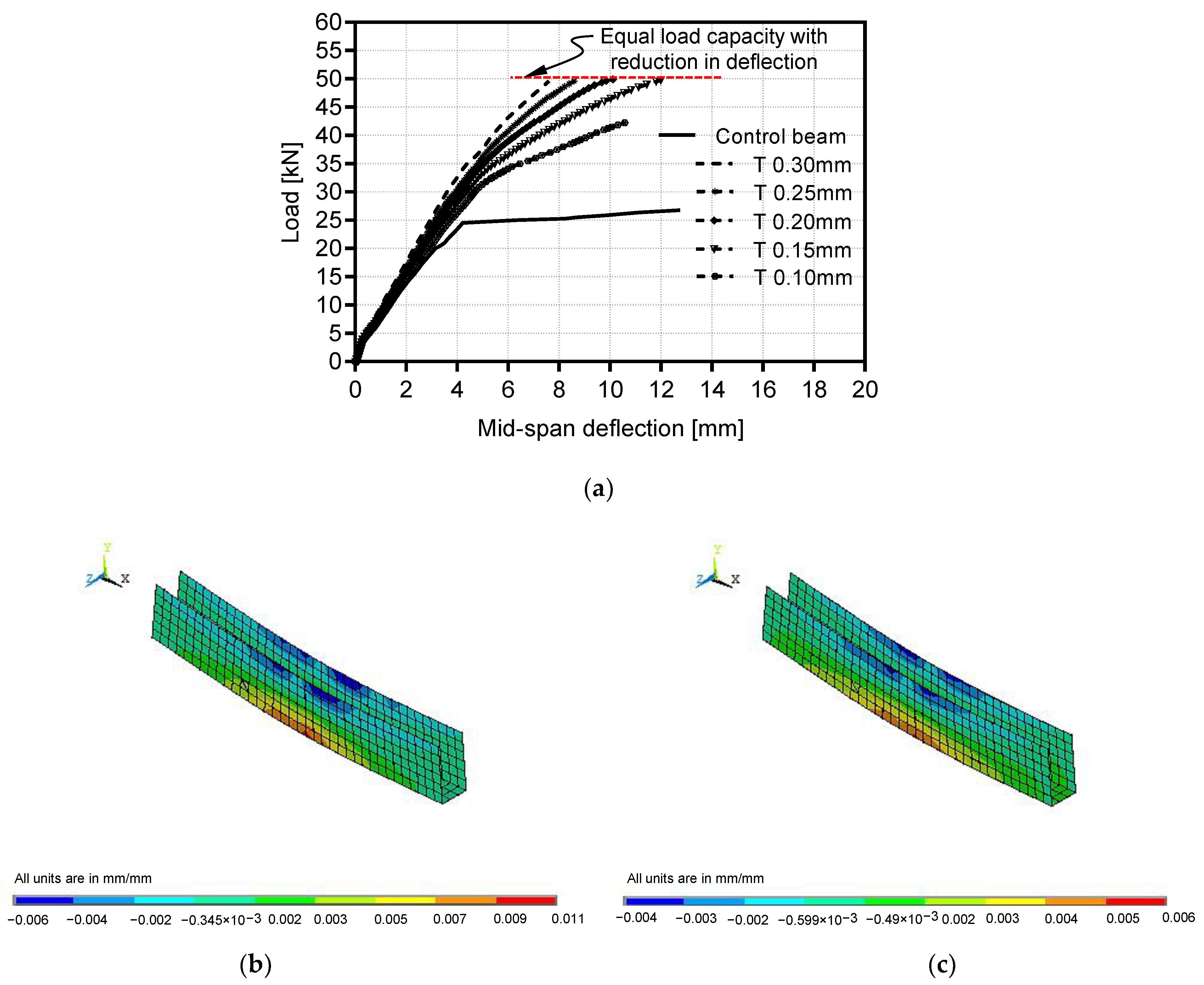
4.3. Effect of Sheet Thickness of Bonded U-Wrapped CFRP

To explore the influence of increasing the thickness of bonded U-wrapped CFRP strips, five distinct thicknesses of 0.1, 0.15, 0.20, 0.25, and 0.30 mm were employed in the FEM. Figure 18 illustrates the various configurations of the U-wrapped CFRP laminates used to strengthen the beams.
Generally, increasing the thickness of U-wrapped CFRP sheets enhances the overall flexural performance of the strengthened beams. The flexural load capacity was boosted by about 58%, while the deflection of the U-wrapped beam with 0.1 mm CFRP sheet thickness was reduced by 17.7% in comparison to the referenced beam. The maximum load increased by 17.7%, 18.1%, 17.5%, and 17.2% when the CFRP sheet thickness was increased from 0.1 mm to 0.15, 0.2, 0.25, and 0.3 mm, respectively. When the thickness of the CFRP laminates was raised from 0.15 mm to 0.2 mm, 0.25 mm, and 0.3 mm, the deflection was lowered by 15.6%, 28.7%, and 36.5%, respectively. As seen in Figure 19a, raising the thickness of U-wrapped CFRP laminates from 0.15 mm to 0.2, 0.25, and 0.3 mm had almost no effect on improving load capacity, but had a substantial impact on reducing deflection. This might be attributable to the fact that all of these beams failed in tension, particularly owing to the failure of tensile steel bars, whereas the sole advantage of raising the thickness of the CFRP laminates was a reduction in deflection as a result of the reduction of the axial strains of the CFRP laminates. The maximum axial strains in the cases of T 0.15 mm and T 0.3 mm were dropped from 0.0109 to 0.0059, with a reduction ratio of 45.9%, as shown in Figure 19b,c.

4.4. Effect of Pre-Tensioned Unbonded External U-Wrapped CFRP Sheets

This section investigates the influence of strengthening beams with external unbonded U-wrapped CFRP sheets of 0.12 mm thickness (UU T0.12 without Pre-T) mechanically affixed to the RC beam’s ends. The bending behavior of this beam was compared to that of a beam strengthened with 0.12 mm thick bonded U-wrapped CFRP sheets (BU T0.12). To enhance the flexural strength of the beam (UU T0.12 without Pre-T), pre-tension stresses of 35%, 45%, and 65% of the maximum tensile strength of the CFRP sheets were applied to the sheets before anchoring. The various pre-tension stress intensities were calculated in order to control the camber and tensile stresses on concrete in the compression zone so that they did not exceed the allowed concrete tensile strength. Figure 20 depicts the FE configurations of bonded and unbonded U-wrapped CFRP sheets with and without pre-tension stresses.
Figure 21 displays the load–deflection curves generated by the FEA for both bonded and unbonded exterior CFRP U-wrapped sheets with and without pre-tension stresses. The bending response of the beam (UU T0.12 without Pre-T) deviated from that of the RC beam (BU T0.12). The ultimate load of the beam (UU T0.12 without Pre-T) was reduced by 22.36% when compared to the beam (BU T0.12). Pre-tension stresses with varied levels were applied to the U-wrapped CFRP sheets to enhance the flexural strength and deflection of the beams strengthened using unbonded U-wrapped CFRP laminates. The flexural behavior of the beam (UU T0.12 with Pre-T 45%) was nearly identical to that of the (BU T0.12), with a 4.47% difference in load capacity and a 16.24% reduction in deflection. This minor variation in load capacity is deemed within the allowed tolerances, and the response of externally bonded (BU T0.12) and unbonded strengthened RC beams utilizing pre-tensioned CFRP U-wrapped sheets (UU T0.12 with Pre-T 45%) may be addressed similarly.

4.5. Effect of Using Exterior Unbonded CFRP Sheets with Different Concrete Grades

To determine the impact of concrete compressive strength on the flexural strength and deformation of strengthened beams using external unbonded CFRP straight-laminates, ANSYS software [48] is used to simulate 12 distinct strengthened RC beams with varying concrete strengths (21, 50, 80, and 120 MPa) and CFRP cross-sectional areas (2.5, 5, and 7.5 mm2). Figure 22 displays the configuration and dimensions of the strengthened RC beams modeled using external unbonded CFRP sheets.
In this section, the analyzed beams were separated into two categories. The first category includes beam groups A, B, and C. Each group of beams has the same CFRP cross-sectional area as the concrete compressive strength increases. In the second category, the beams in each group (D, E, F, and G) have the same concrete compressive strength with an increase in CFRP cross-sectional area.
Figure 23 depicts the load–deflection relations for all modeled strengthened beams. Table 5 shows the maximum values of concrete compression stress, CFRP tensile stress, SRFT tensile stress, ultimate load, ultimate load variance, and maximum midspan deflections. As seen in Figure 23, increasing both the concrete compressive strength and the CFRP cross-sectional area improved the beam’s overall flexural behavior. Under the same load, the beam’s deflection was reduced in the elastic phase of all studied beams, which may allude to the rise in the beam’s overall modulus of elasticity induced by raising the concrete compressive grade.
Furthermore, all of the analyzed beams failed in tension when the tensile stress in the steel reinforcement exceeded the yield strength while the concrete strain in the compression zone was still under failure strain. As seen in Figure 23 and numerically interpreted in Table 5, for the beam groups with the same CFRP cross-sectional area and increased concrete compressive strengths (Group A: B1, B2, B3, and B4), (Group B: B5, B6, B7, and B8), and (Group C: B9, B10, B11, and B12), increasing the concrete compressive strength using the same CFRP cross-sectional area improves only the beam’s load capacity by (29.7%, 49.3%, and 60.8%), (22.3%, 43.5%, and 66.4%), and (30.7%, 61.2%, and 71.6%), comparable to B1, B5, and B9, respectively.
According to Table 5, steel tensile stresses surpassed the steel yield strength at an increasing rate in beams with high concrete compressive strength, i.e., in beams with relatively high concrete tensile strength compared to that of beams with low concrete compressive strength. These beams with high compressive strength have a relatively high concrete tensile strength, which may assist in enhancing steel strain hardening and, as a result, delay the failure of these beams, indicating a significant increase in load capacity in these beams.
As depicted in Figure 23 and quantified in Table 6, in the beam groups with the same concrete compressive grade and increasing in CFRP cross-sectional areas (Group D: B1, B5, and B9), (Group E: B2, B6, and B10), (Group F: B3, B7, and B11), and (Group G: B4, B8, and B12), the load capacity increased by (6.7% and 11%), (0.7% and 11.9), (2.6% and 19.9%), and (10.4% and 18.5%), respectively, when compared to B1, B2, B3, and B4. However, the maximum deflection of these beam groups dropped by (10.6% and 26.4%), (20.4% and 31.6%), (12.8% and 20.4%), and (16.5% and 29.8%), respectively, when compared to B1, B2, B3, and B4.
It is revealed that the rate of increase in ultimate load caused by an increase in concrete compressive strength is greater than that caused by an increase in CFRP cross-sectional area. This finding may refer to that increasing the concrete grade has a substantial impact on improving the strain hardening of steel bars as a result of bond and concrete tensile strength improvement, whereas increasing the cross-sectional area of external CFRP sheets has no physical effect on the strain hardening of steel reinforcement bars.
According to the load variations shown in Table 5 and Table 6, increasing the CFRP cross-sectional area to strengthen RC beams with any constant compressive strength can enhance load capacity by up to 20% (As presented in Table 6). Additionally, using CFRP sheets to strengthen RC beams constructed from high-strength concrete (HSC) is more efficient than using it to strengthen normal concrete (NC) beams, resulting in increasing the ultimate load by 22.3% in the case of NC and by 71.6% in the case of HSC, as shown in Table 5.
The significant benefit that can be acquired by increasing the cross-sectional area of external unbonded CFRP sheets is by reducing the tensile stresses in CFRP sheets, which results in a reduction in the sheet’s axial strain, which in turn reduces the beam’s curvature and mid-span deflection by about 10% in the case of NC to about 30% in the case of HSC, as shown in Table 6.

5. Conclusions

In this work, a finite element analytical model utilizing ANSYS software is utilized to numerically analyze the structural response of CFRP-strengthened beams with external bonded, unbonded, and unbonded pre-tensioned sheets with varied patterns. The FE model’s outcomes were verified by comparing them to previous experimental studies. In addition, a parametric analysis including 30 distinct models was performed to explore the flexural behavior of beams strengthened with external straight and u-wrapped CFRP sheets in terms of flexural strength, failure mode, and deflection. Based on the current study’s findings, it is possible to conclude:
-
The use of unbonded CFRP sheets mechanically affixed to strengthened RC beams, with or without pre-tension stress, provided a creative solution to the durability problem of bonded CFRP sheet detachment.
-
Externally unbonded CFRP sheets with different patterns (straight and u-wrap) that were pre-tensioned with 45% of the CFRP ultimate strength exhibited relatively similar behavior as the corresponding bonded CFRP sheets, with minor differences in load capacity of less than 4.5% and significant reductions in deflection ranging from 9.7% to 16.24%.
-
Raising the thickness of bonded CFRP laminates used to strengthen RC beams that failed due to tensile steel bar yielding has little effect on improving load capacity, but has a significant influence on reducing beam deflection due to reduced axial strain of the thickened CFRP laminates.
-
Using CFRP sheets to strengthen RC beams made of high-strength concrete is more efficient than using it to strengthen normal concrete beams, causing a rise in load capacity ranging from 22.3% for NC to 71.6% for HSC.
-
Increasing the cross-sectional area of exterior unbonded CFRP sheets reduced the sheet’s axial strains, which lowered beam curvature and mid-span deflection by about 10% in the case of NC to nearly 30% in the case of HSC.
Further experimental studies and applications of machine learning techniques are needed to improve the various code provisions for predicting the ultimate design load for strengthened RC beams utilizing externally unbonded CFRP sheets with or without pre-tensioned stresses.

Author Contributions

M.A.E.Z.: Conceptualization, Methodology, Software, Validation, Formal analysis, Investigation, Data Curation, Writing—Original Draft, Visualization, Project administration. S.B.: Methodology, Software, Validation, Data Curation, Writing—Review and Editing, Visualization. M.R.K.: Funding Acquisition, Review and Editing, Visualization. W.E.E.-D.: Conceptualization, Formal analysis, Investigation, Validation, Review and Editing, Supervision. All authors have read and agreed to the published version of the manuscript.

Funding

This research was supported by Basic Science Research Program through the National Research Foundation of Korea (NRF) funded by the Ministry of Education (GN: NRF-2022R1I1A1A01062918).

Data Availability Statement

The data presented in this study are included in the manuscript.

Conflicts of Interest

The authors declare no conflict of interest.

References

  1. Wu, J.; Zhu, Y.; Li, C. Experimental Investigation of Fatigue Capacity of Bending-Anchored CFRP Cables. Polymers 2023, 15, 2483. [Google Scholar] [CrossRef] [PubMed]
  2. Ding, J.; Cheng, L. Experimental study on ultrasonic three-point bending fatigue of CFRP under ultraviolet radiation. Eng. Fract. Mech. 2021, 242, 107435. [Google Scholar] [CrossRef]
  3. Xian, G.; Guo, R.; Li, C. Combined effects of sustained bending loading, water immersion and fiber hybrid mode on the mechanical properties of carbon/glass fiber reinforced polymer composite. Compos. Struct. 2022, 281, 115060. [Google Scholar] [CrossRef]
  4. Siddika, A.; Al Mamun, M.A.; Ferdous, W.; Alyousef, R. Performances, challenges and opportunities in strengthening reinforced concrete structures by using FRPs–A state-of-the-art review. Eng. Fail. Anal. 2020, 111, 104480. [Google Scholar] [CrossRef]
  5. Shomali, A.; Mostofinejad, D.; Esfahani, M.R. Experimental and numerical investigation of shear performance of RC beams strengthened with FRP using grooving method. J. Build. Eng. 2020, 31, 101409. [Google Scholar] [CrossRef]
  6. Su, M.; Gong, S.; Liu, Y.; Peng, H. Flexural behavior of RC beams strengthened with fully or partially prestressed near-surface mounted FRP strips: An experimental investigation. Eng. Struct. 2022, 262, 114345. [Google Scholar] [CrossRef]
  7. Zhou, J.; Wang, X.; Peng, Z.; Wu, Z. Optimization of load transfer component for FRP cable anchor system. Compos. Struct. 2022, 282, 115009. [Google Scholar] [CrossRef]
  8. Zhang, W.; Liu, X.; Huang, Y.; Tong, M.-N. Reliability-based analysis of the flexural strength of concrete beams reinforced with hybrid BFRP and steel rebars. Arch. Civ. Mech. Eng. 2022, 22, 171. [Google Scholar] [CrossRef]
  9. Wakjira, T.G.; Al-Hamrani, A.; Ebead, U.; Alnahhal, W. Shear capacity prediction of FRP-RC beams using single and ensenble ExPlainable Machine learning models. Compos. Struct. 2022, 287, 115381. [Google Scholar] [CrossRef]
  10. Zeng, J.J.; Zeng, W.B.; Ye, Y.Y.; Liao, J.; Zhuge, Y.; Fan, T.H. Flexural behavior of FRP grid reinforced ultra-high-performance concrete composite plates with different types of fibers. Eng. Struct. 2022, 272, 115020. [Google Scholar] [CrossRef]
  11. Hawileh, R.; Musto, H.; Abdalla, J.; Naser, M. Finite element modeling of reinforced concrete beams externally strengthened in flexure with side-bonded FRP laminates. Compos. Part B Eng. 2019, 173, 106952. [Google Scholar] [CrossRef]
  12. Wakjira, T.G.; Abushanab, A.; Ebead, U.; Alnahhal, W. FAI: Fast, accurate, and intelligent approach and prediction tool for flexural capacity of FRP-RC beams based on super-learner machine learning model. Mater. Today Commun. 2022, 33, 104461. [Google Scholar] [CrossRef]
  13. You, Y.-C.; Choi, K.-S.; Kim, J. An experimental investigation on flexural behavior of RC beams strengthened with prestressed CFRP strips using a durable anchorage system. Compos. Part B Eng. 2012, 43, 3026–3036. [Google Scholar] [CrossRef]
  14. Piątek, B.; Siwowski, T.; Michałowski, J.; Błażewicz, S. Development of Bonded/Riveted Steel Anchorages of Prestressed CFRP Strips for Concrete Strengthening. Materials 2020, 13, 2217. [Google Scholar] [CrossRef]
  15. Kadhim MM, A.; Mohammed, M.J.; Chabuk, A.J. Effect of prestressed CFRP plate location on behavior of RC beam strengthened with prestressed CFRP plate. J. Univ. Bombay 2012, 20, 105–113. [Google Scholar]
  16. Piątek, B.; Siwowski, T. Experimental study on flexural behaviour of reinforced concrete beams strengthened with passive and active CFRP strips using a novel anchorage system. Arch. Civ. Mech. Eng. 2022, 22, 45. [Google Scholar] [CrossRef]
  17. Deng, J.; Zhong, M.; Zheng, Y.; Zhu, M. Experimental Study on the Durability of Steel Anchors for Prestressed CFRP Laminates under Accelerated Galvanostatic Corrosion. Materials 2022, 15, 5665. [Google Scholar] [CrossRef] [PubMed]
  18. Kachlakev, D.; McCurry, D. Behavior of full-scale reinforced concrete beams retrofitted for shear and flexural with FRP laminates. Compos. Part B Eng. 2000, 31, 445–452. [Google Scholar] [CrossRef]
  19. Adhikary, B.B.; Mutsuyashai, H.; Ashraf, M. Shear strengthening of Reinforced Concrete Beams Using Fiber-Reinoced Polymer Sheets with bonded Anchorade. ACI Strucural J. 2004, 101, 660–668. [Google Scholar]
  20. Chiew, S.P.; Sun, Q.; Yu, Y. Flexural Strength of RC beams with GFRP Laminates. J. Compos. Constr. ASCE 2007, 11, 497–506. [Google Scholar] [CrossRef]
  21. Pannirselvam, N.; Raghunath, P.N.; Sugma, K. Strength Modeling of Reinforced Concrete Beam with Externally Boned Fibre Reinforced Polymer Reinforcement. Am. J.Eng. Appl. Sci. 2008, 1, 192–199. [Google Scholar]
  22. Tahenni, T.; Bouziadi, F.; Boulekbache, B.; Amziane, S. Experimental and nonlinear finite element analysis of shear behaviour of reinforced concrete beams. Structures 2021, 29, 1582–1596. [Google Scholar] [CrossRef]
  23. Alwash, D.; Kalfat, R.; Al-Mahaidi, R.; Du, H. Shear strengthening of RC beams using NSM CFRP bonded using cement-based adhesive. Constr. Build. Mater. 2021, 301, 124365. [Google Scholar] [CrossRef]
  24. Alhassan, M.; Al-Rousan, R.; Ababneh, A. Anchoring of the main CFRP sheets with transverse CFRP strips for optimum upgrade of RC Beams: Parametric experimental study. Constr. Build. Mater. 2021, 293, 123525. [Google Scholar] [CrossRef]
  25. Miao, W.; Guo, Z.X.; Ye, Y.; Basha, S.H. Shear behavior of composite stone beams reinforced with NSM longitudinal CFRP bars. Constr. Build. Mater. 2023, 363, 129802. [Google Scholar] [CrossRef]
  26. Li, W.; Tang, S.; Huang, X.; Liu, W.; Yang, X.; Shi, T. Carbon fiber-reinforced polymer mesh fabric as shear reinforcement in reinforced concrete beams. J. Build. Eng. 2022, 53, 104433. [Google Scholar] [CrossRef]
  27. Yu, F.; Fang, Y.; Guo, S.; Bai, R.; Yin, L.; Mansouri, I. A simple model for maximum diagonal crack width estimation of shear-strengthened pre-damaged beams with CFRP strips. J. Build. Eng. 2021, 41, 102716. [Google Scholar] [CrossRef]
  28. Carrillo, J.; Rodríguez, D.; Villar-Salinas, S. Contribution of CFRP to the shear strength of retrofitted lightly-reinforced concrete panels. J. Build. Eng. 2021, 44, 102722. [Google Scholar] [CrossRef]
  29. Dong, J.; Wang, Q.; Guan, Z. Structural behaviour of RC beams with external flexural and flexural–shear strengthening by FRP sheets. Compos. Part B Eng. 2013, 44, 604–612. [Google Scholar] [CrossRef]
  30. Shen, Y.; Zhang, D.; Wang, R.; Li, J.; Huang, Z. SBD-K-medoids-based long-term settlement analysis of shield tunnel. Transp. Geotech. 2023, 42, 101053. [Google Scholar] [CrossRef]
  31. Sun, Y.; Fu, W.; Chen, X.; Zhang, Z.; Yu, W.; Li, S. Theoretical and experimental investigations into flexural behavior of existing reinforced concrete beams strengthened by CFRP bars. J. Build. Eng. 2023, 77, 107528. [Google Scholar] [CrossRef]
  32. Abdallah, M.; Al Mahmoud, F.; Tabet-Derraz, M.I.; Khelil, A.; Mercier, J. Experimental and numerical investigation on the effectiveness of NSM and side-NSM CFRP bars for strengthening continuous two-span RC beams. J. Build. Eng. 2021, 41, 102723. [Google Scholar] [CrossRef]
  33. Kadhim, M.M.; Jawdhari, A.R.; Altaee, M.J.; Adheem, A.H. Finite element modelling and parametric analysis of FRP strengthened RC beams under impact load. J. Build. Eng. 2020, 32, 101526. [Google Scholar] [CrossRef]
  34. Parandaman, P.; Jayaram, M. Finite element analysis of reinforced concrete beam retrofitted with different fibre composites. Middle-East J. Sci. Res. 2014, 22, 948–953. [Google Scholar]
  35. Madkour, H.; Maher, M.; Ali, O. Finite element analysis for interior slab-column connections reinforced with GFRP bars using damage plasticity model. J. Build. Eng. 2022, 48, 104013. [Google Scholar] [CrossRef]
  36. Mohamed, R.A.; Zana, A.A.; Jaza, H.M. Nonlinear finite element analysis of reinforced concrete beams strengthened with externally bonded steel plate using ANSYS. Sulaimani J. Eng. Sci. 2017, 4, 41–50. [Google Scholar]
  37. Barour, S.; Zergua, A.; Bouziadi, F.; Kaloop, M.R.; El-Demerdash, W.E. Nonlinear numerical and analytical assessment of the shear strength of RC and SFRC beams externally strengthened with CFRP sheets. Adv. Civ. Eng. 2022, 2022, 8741158. [Google Scholar] [CrossRef]
  38. Hamrat, M.; Bouziadi, F.; Boulekbache, B.; Daouadji, T.H.; Chergui, S.; Labed, A.; Amziane, S. Experimental and numerical investigation on the deflection behavior of pre-cracked and repaired reinforced concrete beams with fiber-reinforced polymer. Constr. Build. Mater. 2020, 249, 118745. [Google Scholar] [CrossRef]
  39. Zidani, M.B.; Belakhdar, K.; Tounsi, A. Finite element analysis of initially damaged beams repaired with FRP plates. Compos. Struct. 2015, 134, 429–439. [Google Scholar] [CrossRef]
  40. Dahmani, L.; Khennane, A.; Kaci, S. Crack Identification in Reinforced Concrete Beams using Ansys Software. Strength Mater. 2010, 42, 232–244. [Google Scholar] [CrossRef]
  41. Sasmal, S.; Kalidoss, S.; Srinivas, V. Nonlinear Finite Element Analysis of FRP Strengthened Reinforced Concrete Beams. J. Inst. Eng. Ser. A 2012, 93, 241–249. [Google Scholar] [CrossRef]
  42. Banu, D.; Barros, R.C.D.; Taranu, N. Numerical Modelling of Two-Way Reinforced Concrete Slabs Strengthened with Carbon Fiber Reinforced Polymers Strips. In Proceedings of the International Conference on Experimental Mechanics, Porto, Portugal, 22–27 July 2012; pp. 22–27. [Google Scholar]
  43. Harihar, A.S.; Kulkarni, D. Finite Element Analysis of Reinforced Concrete Beam Strengthened with CFRP Sheets. Bonfring Int. J. Man Mach. Interface 2016, 4, 206–209. [Google Scholar] [CrossRef]
  44. Gopinath, S.; Prabha, M.; Murthy, A.R.; Iyer, N.R. Modelling of RC Beams Strengthened with Basalt Reinforced Concrete. J. Inst. Eng. Ser. A 2017, 98, 285–291. [Google Scholar] [CrossRef]
  45. Atea, R.S. A case study of flexural performance of reinforced concrete beams bonded with steel plates with different thickness. J. Mater. Res. Technol. 2018, 8, 22–32. [Google Scholar] [CrossRef]
  46. Barour, S.; Zergua, A. Numerical analysis of reinforced concrete beams strengthened in shear using carbon fiber reinforced polymer materials. J. Eng. Des. Technol. 2020, 19, 339–357. [Google Scholar] [CrossRef]
  47. Akram, A.; Hameed, R.; Siddiqi, Z.A.; Riaz, M.R.; Ilyas, M. Finite Element Modeling of RC Beams Strengthened in Flexure Using FRP Material. Arab. J. Sci. Eng. 2014, 39, 8573–8584. [Google Scholar] [CrossRef]
  48. Meng, B.; Xiong, Y.; Zhong, W.; Duan, S.; Li, H. Progressive collapse behaviour of composite substructure with large rectangular beam-web openings. Eng. Struct. 2023, 295, 116861. [Google Scholar] [CrossRef]
  49. ANSYS. Release Version 19: A Finite Element Computer Software and User Manual for Nonlinear Structural Analysis; ANSYS Inc.: Canonsburg, PA, USA, 2022. [Google Scholar]
  50. American Concrete Institute. ACI 440.2-17: Guide for the Design and Construction of Externally Bonded FRP Systems for Strengthening Concrete Structures; American Concrete Institute: Farmington Hills, MI, USA, 2017. [Google Scholar]
  51. American Concrete Institute. ACI 318–19: Building Code Requirements for Structural Concrete and Commentary; American Concrete Institute: Farmington Hills, MI, USA, 2019. [Google Scholar]
Figure 1. Dimensions, steel bars details, and CFRP configurations of the experimental study [47]. (a). Geometry and steel bars detailing of the tested control beam, (b). Strengthening of the beam using external bonded CFRP (method-1), (c). Strengthening of the beam using external bonded CFRP (method-2), and (d). Strengthening of the beam using external bonded CFRP (method-3).
Buildings 13 02528 g001
Figure 2. 3D finite element model of the tested beam.
Buildings 13 02528 g002
Figure 3. Geometry of SOLID65 element [45].
Buildings 13 02528 g003
Figure 4. Geometry of LINK180 element [49].
Buildings 13 02528 g004
Figure 5. Geometry of SOLID185 element [49].
Buildings 13 02528 g005
Figure 6. Geometry of SHELL181 element [49].
Buildings 13 02528 g006
Figure 7. Experimental and FEM load-deflection relationships for referenced and strengthened beams. (a) Control beam, (b) Method-1 (CFRP- full wrap), (c) Method-2 (CFRP—half wrap), (d) Method-3 (CFRP strip), (e) Experimental outcomes, and (f) FEM outcomes.
Buildings 13 02528 g007aBuildings 13 02528 g007b
Figure 8. Typical crack pattern in FEM.
Buildings 13 02528 g008
Figure 9. Progression of crack pattern of control RC-beam in FEM.
Buildings 13 02528 g009
Figure 10. Progression of the crack pattern of Method-1 strengthened beam in FEM.
Buildings 13 02528 g010
Figure 11. Progression of the crack pattern of Method-2 strengthened beam in FEM.
Buildings 13 02528 g011
Figure 12. Progression of the crack pattern of Method-3 strengthened beam in FEM.
Buildings 13 02528 g012
Figure 13. Layout and dimensions of the RC-beams strengthened with varying CFRP straight strips.
Buildings 13 02528 g013
Figure 14. Outcomes of the FEMs for beams strengthened with bonded CFRP straight sheets. (a) Load-deflection curves, (b) Maximum normal stresses of beam W25, (c) Maximum normal stresses of beam W50, and (d) Maximum normal stresses of beam W75.
Buildings 13 02528 g014
Figure 15. FE models for RC beams strengthened using bonded and unbonded CFRP straight sheets. (a) FEM for bonded CFRP straight sheet (B75), (b) FEM for unbonded CFRP straight sheet (U75), and (c) FEM for unbonded CFRP straight sheet with a pre-tension force.
Buildings 13 02528 g015
Figure 16. Load-deflection relationships for RC beams strengthened using bonded, unbonded, and pre-tensioned unbonded CFRP straight sheets.
Buildings 13 02528 g016
Figure 17. Maximum camber at beam’s mid-span and normal stresses of the strengthened beam under beam’s self-weight and maximum pre-tension force.
Buildings 13 02528 g017
Figure 18. Layout and dimensions of the beams strengthened using varying thicknesses of CFRP U-wrap.
Buildings 13 02528 g018
Figure 19. Load-deflection curves and axial strains for bonded U-wrapped CFRP sheets with various thicknesses. (a) load-deflection curves, (b) Axial strain of U-wrapped sheet of T 0.15 mm, and (c) Axial strain of U-wrapped sheet of T 0.3 mm.
Buildings 13 02528 g019
Figure 20. FE models for RC beams strengthened using bonded and unbonded U-wrapped CFRP sheet. (a) FEM for bonded U-wrapped CFRP sheet (BU T0.12), (b) FEM for unbonded U-wrapped CFRP sheet (UU T0.12 without Pre-T), (c) FEM for unbonded U-wrapped CFRP sheet (UU T0.12 with Pre-T).
Buildings 13 02528 g020
Figure 21. Load–deflection relationships for beams strengthened with bonded and unbonded CFRP U-wrapped sheets.
Buildings 13 02528 g021
Figure 22. Layout and dimensions of the strengthened beams having different concrete compressive strengths and various sizes of CFRP straight-sheet.
Buildings 13 02528 g022
Figure 23. Load–deflection curves of strengthened RC beams with different concrete compressive strengths and various external unbonded CFRP cross-sectional area.
Buildings 13 02528 g023
Table 1. Characteristics of the concrete material used in the FE model.
Element TypeMaterial Properties
Linear isotropicModulus of elasticity (EX), MPa20,085.49
Passion’s ratio (PRXY)0.2
Multilinear Open shear transfer factor, βt0.5
isotropicClosed shear transfer factor, βc0.9
Uniaxial cracking stress, MPa2.84
Uniaxial crushing stress, MPa21
Stress–strain relationship:
Stress–strain pointsStress (MPa)Strain (mm/m)
100
SOLID65 210.530.5244
312.590.65
414.750.80
517.051.00
618.751.20
719.891.40
820.591.60
920.931.80
1020.992.00
1120.842.20
12211.95
13213.00
Table 2. Characteristics of steel bars used for FE models.
Element TypeMaterial Properties
Linear-isotropicModulus of elasticity (EX), MPa198,000
LINK180 Passion’s ratio (PRXY)0.3
Bilinear-isotropicYield stress, MPa278
Tangent modulus *, MPa---
*: The tangent modulus was taken constant and equal to zero for the steel behavior of elastic-perfect plastic.
Table 3. Properties of FRP materials used in the study [47].
Material of LaminatesCFRP
Design thickness, tcf, mm0.12
Modulus of elasticity, Ecf, GPa231
Ultimate tensile strength, fucf, MPa4100
Table 4. Experimental and numerical modeling results.
Reinforced Concrete BeamsPu (kN)Difference (%)Δu (mm)Difference (%)
Exp.FEMExp.FEM
Control19.8421.377.679.978.8910.83
Method-1 (CFRP—full wrap)33.4333.500.209.759.096.76
Method-2 (CFRP—half wrap)36.8238.624.889.998.8211.71
Method-3 (CFRP strip)27.9528.401.619.6510.69.84
Table 5. Variances in ultimate load capacity of strengthened beam groups with different concrete compressive strengths and constant external unbonded CFRP cross-sectional area per each group.
Group of BeamBeam IDComp. Strength, fc, MPaCFRP Area, Acf, mm2Max. Compression Stress, MPaCFRP Max. Tensile Stress, MPaSRFT Max. Tensile Stress, MPaUltimate Load, Pu, kNVariance in Ultimate Load *, %Max. Deflection, Δmax, mm
Group AB1212.5−11.2661645326.130.09.97
B2502.5−40.6086247133.88+29.712.48
B3802.5−66.15164553139.00+49.317.28
B41202.5−82.90170855242.00+60.820.78
Group BB5215.0−21.3051244127.880.08.91
B6505.0−39.0071946734.11+22.39.93
B7805.0−67.30158651240.00+43.515.06
B81205.0−75.90167454146.38+66.417.36
Group CB9217.5−17.5045843229.000.07.34
B10507.5−26.7070245637.90+30.78.54
B11807.5−69.98124850146.75+61.213.76
B121207.5−75.00162552249.75+71.614.59
*: A positive sign means an increase in load capacity.
Table 6. Variances in ultimate load capacity and deflection of strengthened beam groups with different external unbonded CFRP cross-sectional area and constant concrete compressive strengths per each group.
Group of BeamBeam IDComp. Strength, fc, MPaCFRP Area, Acf, mm2CFRP Max. Tensile Stress, MPaSRFT Max. Tensile Stress, MPaUltimate Load, Pu, kNVariance in Ultimate Load *, %Max. Deflection, Δmax, mmVariance in Max. Deflection **, %
Group DB1212.561645326.130.09.970.0
B521551244127.89+6.78.91−10.6
B9217.545843229.00+117.34−26.4
Group EB2502.586247133.880.012.480.0
B6505.071946734.11+0.79.93−20.4
B10507.570245637.90+11.98.54−31.6
Group FB3802.5164553139.000.017.280.0
B7805.0158651240.00+2.615.06−12.8
B11807.5124850146.75+19.913.76−20.4
Group GB41202.5170855242.000.020.780.0
B81205.0167454146.38+10.417.36−16.5
B121207.5162552249.75+18.514.59−29.8
*: positive sign means increasing in load capacity. **: negative sign means decreasing in deflection.
Disclaimer/Publisher’s Note: The statements, opinions and data contained in all publications are solely those of the individual author(s) and contributor(s) and not of MDPI and/or the editor(s). MDPI and/or the editor(s) disclaim responsibility for any injury to people or property resulting from any ideas, methods, instructions or products referred to in the content.

