Article

Optimal Design of Nonlinear Negative-Stiffness Damper with Flexible Support for Mitigating Cable Vibration

State Key Laboratory for Geomechanics & Deep Underground Engineering, School of Mechanics and Civil Engineering, China University of Mining and Technology, Xuzhou 221116, China
*
Author to whom correspondence should be addressed.
Buildings 2023, 13(10), 2620; https://doi.org/10.3390/buildings13102620
Submission received: 14 September 2023 / Revised: 9 October 2023 / Accepted: 15 October 2023 / Published: 17 October 2023
(This article belongs to the Section Building Structures)

Abstract

:
Negative-stiffness damper is a promising device to mitigate cable vibrations effectively. In contrast to traditional rigid supports, recent study has found that flexible supports are actually beneficial for enhancing the performance of negative-stiffness dampers. This study extends the understanding of the impact of support flexibility under nonlinear condition, followed by an optimization process to obtain required negative-stiffness dampers and corresponding supports. First, taking damping nonlinearity into account, a unified model is established for the negative-stiffness damper with flexible support. Theoretical equivalent negative stiffness and damping are obtained for a linear case, followed by numerical verification. Thereafter, equivalent parameters under a friction case are presented. Experiments are conducted to validate the analytical derivation. Then, problem formulation is developed for the controlled cable. Optimization process is proposed to determine the required negative-stiffness damper and support for multimodal cable vibration. A series of numerical simulations are performed to demonstrate the design process. Moreover, nonlinear examples are presented to show the potential for improving control performance. As indicated by the research results, a flexible support is capable of amplifying the equivalent negative stiffness and damping under linear and nonlinear conditions. For multimodal cable vibration, it is sufficient to determine the optimized negative stiffness and support by only considering the highest mode. Nonlinear negative-stiffness dampers exhibit superior performance due to the leakage of vibration energy toward high-order modes.

1. Introduction

As essential components in cable-stayed bridges, stay cables play key roles in carrying various loads. However, stay cables often suffer kinds of vibrations due to their extremely low inherent damping and harsh external environment. Vibrations with large amplitudes or high frequencies might cause harmful effects on the cables, such as accelerating fatigue or promoting pedestrians’ anxiety. To reduce harmful vibrations, attaching mechanical dampers near the anchorage is widely utilized over the world.
Obviously, merely installing dampers for mitigating cable vibration has inevitable disadvantages. Cables are continuous components with large length, while dampers are usually attached discretely close to the bridge’s deck. Recent studies, including field monitoring and wind tunnel tests, have found that cable vibrations are increasing in complexity [1,2,3,4,5]. Especially for the ultra-long stay cables, traditional dampers are gradually unable to provide sufficient damping to mitigate cable vibrations. Thus, there is an urgent need to develop new dampers or methods with outstanding performance. Using a tuned mass damper, Zhang and Xu [6] proposed an optimization procedure involving nonlinear aeroelastic effect for the galloping/flutter control of structures that may experience large-amplitude vibrations. Chen et al. [7] designed a type of viscoelastic damper, which consists a housing box containing a viscous medium and shear plates immersed in the viscous medium. A comprehensive performance comparison of the proposed viscoelastic damper and viscous damper was then carried out on three cables of one long-span bridge. As shown by the results, the measured damping provided by the proposed damper agreed well with the theoretical predictions. Lu et al. [8] examined the potential of the viscous inertial mass damper to enhance the damping for stay cables. As can be seen, the modal damping ratio achieved by the viscous inertial mass damper could be up to an order of magnitude larger than that of traditional linear viscous damper. Similar inertial dampers were then further investigated in [9,10]. By connecting tuned inerter dampers with series or parallel stiffness, Shi et al. [11] systematically investigated their vibration mitigation mechanism. To suppress multimodal cable vibrations, Gao et al. [12] proposed an optimum design procedure for the viscous inerter damper based on the output feedback control theory.
Besides the innovative dampers above, a negative-stiffness damper is another promising type, which has attracted increasing attention in recent years. Being different from common dampers, negative-stiffness dampers exhibit unique mechanical characteristics with a negative-stiffness slope in the damping force. At the earliest, such a negative-stiffness behavior was realized by using semi-active or active devices [13,14]. However, semi-active or active modes need support from other systems, for example, sensors in real time, reliable long-term power, and necessary algorithm unit, etc. The complexity of the control system was increased and practical applications became even less likely. Xu et al. [15] proposed a programmable pseudo-negative-stiffness control device, which possessed advantages of low energy consumption, less real-time calculation, and dynamic input. Passive dampers that could provide negative-stiffness force naturally were then developed for controlling undesired vibrations. A type of adaptive negative-stiffness device was suggested for protecting structures and highway bridges under seismic loads [16,17,18]. In this device, one pre-pressed spring was explored with an amplification mechanism to achieve required control force. By assembling a pre-pressed spring with a discrete viscous damper, Chen et al. [19] developed a negative-stiffness damper for stay cables. Furthermore, using two pre-pressed springs perpendicular to the direction of a piston rod, Zhou and Li [20] proposed a passive negative-stiffness damper and investigated its control performance for model cables. As can be seen in the experiments, an excellent reduction effect for cable vibration was found due to the superior ability of energy dissipation of the proposed device. Also, such a negative-stiffness device was suggested to interconnect two cables into a cable network [21]. As can be seen clearly, additional damping was added to both cables simultaneously. Liu et al. extended this idea by introducing a shape memory alloy to a negative-stiffness damper to develop a new device with the characteristics of self-centering for the seismic protection of a single-degree-of-freedom structural system [22]. As indicated by their numerical results, both the acceleration as well as the displacement responses were dramatically decreased. By arranging several permanent magnets in a conductive pipe, Shi and Zhu [23,24,25] integrated negative stiffness with eddy-current damping to form a novel magnetic device. The device was able to reduce cable vibration significantly.
Another noteworthy aspect is the installed location of the above dampers. Generally, the higher the dampers are attached, the better the control effect can be achieved. However, taking bridge aesthetic requirements into account, the installation usually recommends including about 2% of the cable length. In particular, for super-long cables, the supports would need a large height to install dampers in the required position. As a result, high supports might introduce relative flexibility. Hence, choosing proper stiffness for supports has been found to be crucial to ensure the control effectiveness. For traditional dampers, including positive stiffness or zero stiffness, the supports’ stiffness levels need to be high enough as implied by a number of studies. Xu and Zhou [26] investigated the performance of SMA-based adjustable fluid dampers, in which flexible support would lead to adverse effects. For viscous dampers, asymptotic solutions of additional damping for cables were derived. A finite stiffness support would cause considerable reduction in attainable damping levels. Also, the experimental results in [27] indicated similar trends. Support stiffness had a remarkable influence on the efficiency of the linear viscous damper. With increasing support stiffness, the achievable damping ratio increased. Besides linear viscous dampers, Huang and Jones [28] also investigated the case of nonlinear friction dampers. An imperfectly rigid support would reduce the effectiveness of nonlinear dampers in controlling cable vibrations. For negative-stiffness dampers, the situation becomes different. Javanbakht et al. [29,30] defined a dimensionless index to present the support stiffness for linear viscous damping. Then, a refined design formula is derived for a cable. Results showed that, a flexible support, rather than a rigid one, had advantages in improving damping levels for cables. By utilizing the benefit of flexible supports, negative-stiffness dampers could be designed cost-effectively, while maintaining the same control effect as that of a linear quadratic regulator algorithm. Zhou et al. [31] developed a prototype of a nonlinear negative-stiffness damper, which behaved as a Coulomb friction. Both theoretical and experimental results showed that flexible support could amplify the equivalent negative-stiffness and friction parameters. Dong and Cheng [32] conducted an experimental study to investigate the effect of support stiffness on the efficiency of a negative-stiffness damper with linear viscous damping. Chen et al. [33] proposed a practical negative-stiffness device for cable damping improvement. When the negative-stiffness damper was combined with a viscoelastic damper in series, high effectiveness was found due to the amplification of deformation amplitudes.
As discussed above, the flexibility of supports has a great impact on the control performance of dampers for cable vibrations. Existing studies mainly focus on the linear viscous damping condition for negative-stiffness dampers when support flexibility is taken into account. The impact of flexible supports on negative-stiffness dampers with nonlinear viscous damping has not been fully investigated. The present study aims to extend the current understanding on the impact of support flexibility for linear or nonlinear viscous damping negative-stiffness dampers.
For clarity, the methods used in this paper are listed as follows. For linear viscous damping cases in Section 2, theoretical derivations are combined with numerical simulations. For nonlinear viscous damping in Section 2, the main method is experimental testing. For the optimization of negative-stiffness dampers and supports in Section 3, numerical simulations are mainly performed to demonstrate the optimization of negative-stiffness dampers with flexible supports.

2. Negative-Stiffness Damper with a Flexible Support on Cables

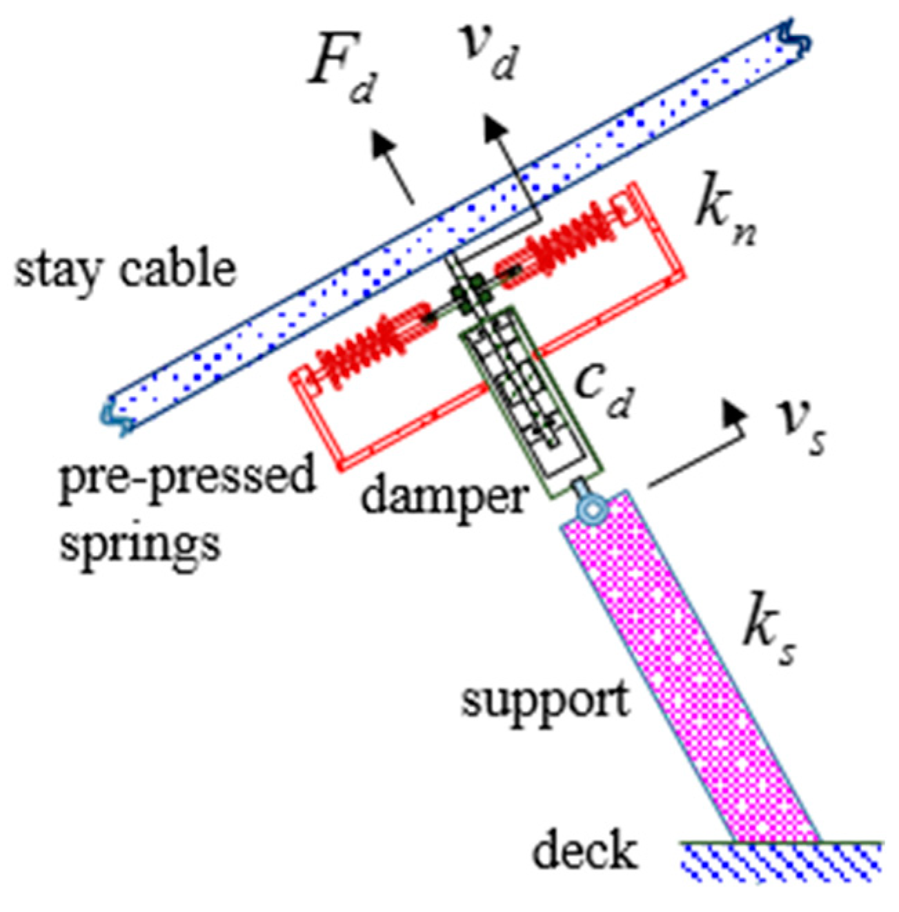
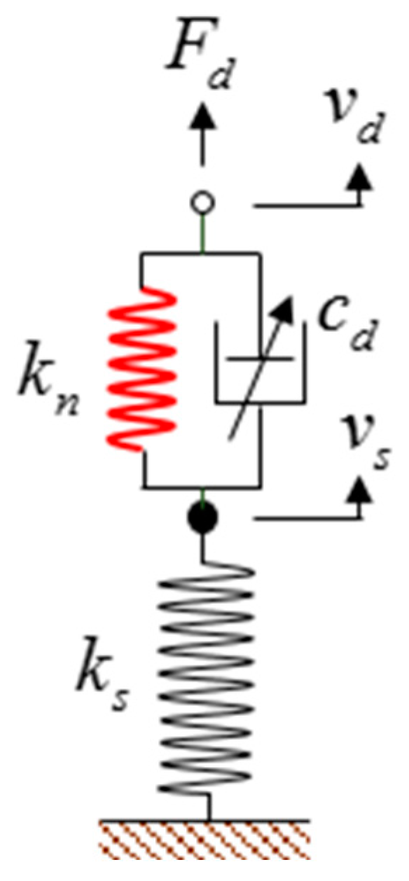
2.1. Simplified Model of the Damper Support System

On actual bridges, a common installation method for the kinds of dampers is detailed in Figure 1. Usually, one end of the damper is attached on the target cable near the lower anchorage. The other end is in series with a support. The support is then connected to the deck of cable-stayed bridges. The damper provides basic damping force while pre-pressed springs are assembled to the piston rod of the damper in a symmetrical way. When the piston rod moves with the cable, the pre-pressed springs move together to provide negative-stiffness behavior.
Imperfect factors in the connection, such as friction and gaps, are ignored. Considering the large weight of the cable itself, the influence of the weight of the springs and damper is also neglected. Therefore, ideal mechanical components are utilized to represent mechanical behavior. Meanwhile, the cable is assumed to vibrate along the axial direction of the damper and support. The influence of the installation angle is not considered. According to the specific layout, a simplified mechanical model is established to represent the dynamic behavior of the damper support system. As shown in Figure 2, the damping force provided by the damper is related to its velocity. To consider the nonlinearity of damping force, a velocity index is introduced. Within small displacement, the negative stiffness provided by two pre-pressed springs is almost linear. Therefore, a virtual spring with a negative-stiffness coefficient is adopted, although such a spring does not really exist.
The support is generally made of steel components with a certain axial stiffness. Due to the assumption of imperfect rigidity, the support would experience additional deformation under action of external force. Thus, a natural spring with a positive stiffness coefficient is utilized to replace the support in the mechanical model. Then, the control force provided by the nonlinear negative-stiffness damper with a flexible support can be written as follows:
F d = k n ( v d v s ) + c d | v ˙ d v ˙ s | α sgn ( v ˙ d v ˙ s )         = k s v s
where F d is the control force of the nonlinear negative-stiffness damper, considering the effect of support flexibility; k n is the negative-stiffness coefficient determined by two pre-pressed springs; c d is the viscous damping coefficient achieved by the damper; α is the velocity index indicating the exponential relationship between damping force and velocity, in which 0 represents friction and 1 represents linear viscous damping; v d and v ˙ d are the displacement and velocity responses of the negative-stiffness damper, respectively; v s and v ˙ s are the displacement and velocity responses across the support, respectively; and k s is the stiffness coefficient of the support, which would approach infinity for a perfect rigidity case.
Actually, negative-stiffness behavior introduced by the pre-pressed spring is not naturally stable. There is a lower limit for support stiffness to ensure the damper support system stability:
k n + k s > 0

2.2. Equivalent Model for the Case of Linear Viscous Damping

Firstly, the linear viscous damping case is considered. The velocity index is equal to unity. At this point, Equation (1) degenerates into the form:
k n ( v d v s ) + c d ( v ˙ d v ˙ s )     = k s v s
To study the effect of flexible supports, a simple harmonic vibration is chosen as the starting condition. Simple harmonic vibration is a relatively simple type of vibration, and its response has a sinusoidal form. For simplification, it is assumed that the displacement of the damper has the form v d = sin ω t for initial theoretical derivation. Moreover, the two following dimensionless parameters are introduced:
χ = k s / k n < 1
γ = ω c d / k n < 0
where ω is the circular frequency of the sinusoidal displacement load, χ is the ratio of the support stiffness to the negative stiffness, and γ is the ratio of damping force to the negative stiffness.
Under this condition, the displacement response of the support can be presented as
v s = a 1 sin ω t + a 2 cos ω t
where a 1 and a 2 are the amplitude coefficients determined by Equation (3) with the following expression:
a 1 = 1 + χ + γ 2 ( 1 + χ ) 2 + γ 2
a 2 = χ γ ( 1 + χ ) 2 + γ 2
Substituting the obtained support displacement, the equivalent mechanical model for the linear negative-stiffness damper with a flexible support is simplified as
F d = k e q v d + c e q v ˙ d
where k e q and c e q are the equivalent negative stiffness and damping, respectively, with the following representations:
k e q = χ ( 1 + χ + γ 2 ) ( 1 + χ ) 2 + γ 2   ·   k n
c e q = χ 2 ( 1 + χ ) 2 + γ 2   ·   c d
As shown by the aforementioned deduction, the dimensionless parameter γ is frequency dependent. As a result, the equivalent negative stiffness and damping are also frequency dependent. For complex displacement loads, such as random or multi-frequency, analytical solutions cannot be obtained through a similar process. Thus, a numerical model is established according to the force relationship in Equation (3) using Simulink module of MATLAB 2016a. Figure 3 presents the details of the calculation process. The displacement v d is adopted as the input, while the equivalent damping force is calculated as output.
Equations (10) and (11) reveal the influence of a flexible support on the equivalent damping force. Compared to the existing negative stiffness and viscous damping, different coefficients are introduced. To show the influence clearly, numerical and theoretical methods are explored through an example of a negative-stiffness damper with different supports. As a result, the negative stiffness is arbitrarily taken as kn = −2 KN/mm, while a relatively small value of cd = 0.1 KN·s/mm is selected. Based on the level of the negative stiffness, two support options are chosen, one is k s = 20   kN / m m and the other is 3   kN / m m , to highlight the impact of flexibility. As plotted in Figure 4a, the hysteresis loops of the negative-stiffness damper with a perfectly rigid support behave as the red dashed line. For the support k s = 20   kN / m m , at the beginning, some derivations occur between theoretical and numerical results. After that, numerical results coincide with the theoretical results very well. At this point, the support stiffness is relatively high. The hysteresis loops of the damper support system is closer to the situation of rigid support. When the support stiffness declines to k s = 3   kN / m m , a large amount of flexibility is introduced. Significant changes occur to the hysteresis loops of the damper support system. As can be seen in Figure 4b, the negative-stiffness trend is greater than that of the rigid support. Moreover, the area enclosed by the hysteresis loops becomes larger, which indicates the improvement in energy dissipation capacity. Therefore, for negative-stiffness dampers, flexible yet rather rigid supports, might have potential advantages. Similar potential advantages under a linear viscous damping condition for negative-stiffness dampers have also been found by the authors of previous studies [29,30,32,34].
Figure 5 further describes the variation laws of keq/kn and ceq/cd with the index χ under various levels of γ . When γ = 0.1 , the damping level is relative low; k e q / k n firstly increases gradually with χ to a peak value of 5.05, and then drops rapidly. That is, with the support changing from rigid to flexible, the equivalent negative stiffness increases slowly, following a quick decline. At the maximum point, the equivalent stiffness of the damper support is magnified by about 5 times compared to the original negative stiffness. In the case of γ = 0.1 , with χ increasing from −5 to −1, the value of c e q / c d continuously increases to greater than 10, indicating that the equivalent damping of the damper support system is about 10 times larger than the original damping due to the flexibility of the support. When γ changes to −0.5, the curves of k e q / k n and c e q / c d drop as a whole. With γ increasing to −1 and −2, and the values of k e q / k n and c e q / c d dropping even below unity.
Therefore, in the case of the linear viscous damping, the influence of flexible supports on the negative-stiffness dampers is related to the defined parameters of χ and γ. When γ approaches zero, k e q / k n and c e q / c d would reach a peak value far greater than unity, with χ closer to negative unity. This is of great significance for practical applications. The equivalent negative stiffness and damping obtained by applying flexible supports would increase dramatically in numerical value compared to the original dampers, thereby achieving an efficient and economical design of negative-stiffness dampers.

2.3. Equivalent Model for the Case of Friction

In the previous section, the case of linear viscous damping was studied. This section will investigate the equivalent control force when the negative-stiffness damper has strong nonlinearity.
When the velocity index α = 0 , the damping force of the viscous damper alters and becomes the Coulomb friction force. Equation (1) can thus be rewritten as
k n ( v d v s ) + f 0 sgn ( v ˙ d v ˙ s )     = k s v s
where f 0 is the Coulomb friction force.
Through a derivation similar to the linear viscous damping case, equivalent parameters of the nonlinear damper support system are obtained as
k e q = χ 1 + χ   ·   k n
f e q = χ 1 + χ   ·   f 0
where k e q is the equivalent negative stiffness under the case of Coulomb friction condition, f e q is the equivalent friction coefficient of the damper support system, and χ = k s / k n is the ratio of support stiffness to the negative stiffness of the original damper.
As shown in Equations (13) and (14), the effect of flexible supports on the equivalent parameters under nonlinearity differs greatly from that under linearity. The equivalent negative stiffness and equivalent friction coefficient have the same variation pattern, which only depends on the ratio of support stiffness to the negative stiffness of the original damper.
Experimental study is carried out to investigate the influence of flexible supports on the nonlinear negative-stiffness dampers for further verification. Figure 6 demonstrates the test setup. A prototype of a nonlinear negative-stiffness damper is fabricated. The original negative stiffness provided by two pre-pressed springs is k n = 8.75   N / mm , while the Coulomb friction level is f 0 = 31   N . A series of tension–compression dual-purpose springs are designed with finite stiffness to simulate flexible supports. For comparison, steel rods with a diameter of 8 mm act as rigid supports for axial connection. The prototype damper is used to study the impact of support flexibility. In total, four levels of support stiffness are performed in experiments. The impact of support flexibility on damping force from the experimental results are then compared with theoretical predictions. As can be seen, the current prototype is still too small for a full-scale stay cable. Thus, numerical simulation will be adopted as the main method in the following studies.
When the stiffness of the designed tension–compression spring is 24.2 N/mm, the experimental results are presented in Figure 7. In the tests, the amplitude of the sinusoidal displacement load is 8 mm and the frequency is 0.5 Hz. As can be seen clearly, the negative-stiffness slope of the hysteresis loops for the flexible support is −14.0 N/mm, while the friction level is 48.7 N. Both parameters are remarkably larger than that under rigid support. Integrating along the hysteresis curve for one cycle, the energy dissipated by the damper under rigid support is 0.82 J, while the energy dissipated under flexible support is 1.12 J with a relative increase of 36.3%.
Using more tension–compression springs with different levels of stiffness, a series of tests is conducted under various displacement loads. According to the experimental results, equivalent negative stiffness and equivalent friction are identified and listed in Table 1. With the support gradually changing from rigid to flexible, it is found that equivalent negative stiffness and equivalent friction show an increasing trend. For the nonlinear negative-stiffness damper, flexible supports actually play beneficial roles, achieving a higher absolute equivalent coefficient, thereby improving the energy dissipation capacity.
Figure 8 compares the experimental and theoretical results for equivalent parameters of a nonlinear negative-stiffness damper with flexible supports. The horizontal axis is the dimensionless index χ representing the flexibility of the supports. The vertical axis is the ratio of equivalent parameters to the original parameters. As can be seen clearly, our experimental results agree well with the theoretical results.
By comparing the solid blue line with circle in Figure 5 with the solid blue line in Figure 8, the way in which the nonlinearity affects the equivalent parameters under flexible supports can be observed. As the damping approaches zero, the ratio of equivalent negative stiffness to original stiffness under the linear state in Equation (10) approaches χ/1+χ, which is only the result of the friction case in Equation (13). For the damping itself, the ratio of equivalent damping to the original damping under linear state in Equation (11) degenerates to (χ/1+χ)2, which is the square of the ratio in Equation (14) under the friction case. Thus, in the case of small damping, the influence of linearity and nonlinearity on the equivalent negative stiffness tends to be similar.
To show the novelty of the present work, Table 2 compares the present work with previous studies. The type of dampers, mechanical characteristics, and support flexibility are taken into account. For negative-stiffness dampers, the aforementioned literature mainly investigated the condition of linear viscous damping. In the present work, a unified model that can consider both linear and nonlinear conditions is established. On this basis, an optimization process will be developed to determine the required negative-stiffness dampers and the corresponding supports in the following section.

3. Optimization of Negative-Stiffness Damper with a Flexible Support for Cable Vibration Control

3.1. Problem Formulation

Cables are inclined on bridges with certain degrees of sag. Figure 9 shows the arrangement of a nonlinear negative-stiffness damper with a flexible support for the targeted cable. Without considering secondary factors of sag, bending stiffness, etc., the dynamic behavior of the cable is modeled as a taut string. The negative-stiffness damper is equipped near the lower anchorage using a flexible support.
Within small amplitudes, the in-plane vibration of the cable can be written as
m v ¨ + c v · T v = F d ( t ) δ ( x a ) + f e ( x , t )
where m is the mass per unit length of the cable; c is the damping per unit length of the cable itself; T is the tension force along the axial direction; v , v ˙ , and v ¨ are the displacement, velocity, and acceleration responses of the cable, respectively; v is the second-order derivative of the displacement with respect to space; and f e ( x , t ) is the external loads acting on the cable. The control force provided by the nonlinear negative-stiffness damper with a flexible support F d ( t ) applies at position a with the following expression:
F d ( t ) = k n [ v ( a , t ) v s ( t ) ] c d | v ˙ ( a , t ) v ˙ s ( t ) | α sign ( v ˙ ( a , t ) v ˙ s ( t ) )
where k n and c d are parameters of the nonlinear negative-stiffness damper with velocity index α ; v ( a , t ) is the cable displacement response at damper location; and v s ( t ) is the displacement response introduced by support flexibility.
Two ends of the cable are fixed to the deck and tower, respectively. Thus, the boundary condition for the system motion equations above is written as
v ( 0 , t ) = v ( l , t ) = 0
where l is the cable length.

3.2. Optimized Parameters of Linear Negative-Stiffness Damper with a Flexible Support

Firstly, the variation of damping ratio achieved by the linear negative-stiffness damper with a flexible support for a single-mode cable vibration is investigated. Through an eigenvalue analysis of the system motion equation, the damping ratio added to one mode of the cable is derived as [13]
ξ n a / l = η n π a / l ( 1 + β ) 2 + ( η n π a / l ) 2
where ξ n is the additional modal damping ratio for the n th mode of the cable; β and η are dimensionless negative stiffness and damping coefficient specifically defined as:
β = k e q T / a
η = c e q T m
Given the required damping ratio for the selected single mode of the cable, the values of equivalent negative stiffness and damping coefficient can be calculated according to Equation (18). Then, the needed damper parameters of k n and c d , and support stiffness k s , can be further obtained utilizing Equations (10) and (11).
Moreover, the damping added by an ideal linear negative-stiffness damper with flexible supports is modal dependent as can be seen in Equation (18). That is, for different modes, the additional damping varies with mode number. However, a large number of actual bridge monitoring results have found that cable vibrations exhibit multimodal characteristics in recent years. For example, under the action of wind speed profile, the frequency ranges of shedding vortex along the cables cover multiple modes, which leads to high-order multimodal vortex-induced vibrations. The highest mode even exceeds the 20th order, with a frequency up to about 25 Hz [35]. Therefore, optimizing the parameters of the damper and support system under multimodal conditions has a more practical significance.
Figure 10 summarizes the variation of additional damping for the first nine modes of the cable. The horizontal axis is the dimensionless damping. The vertical axis is the ratio of the additional damping to the damper location. When the equivalent stiffness of the damper is k e q = 0 , i.e., the case of linear viscous damping, the curves of the additional damping for higher modes shift toward the left. As a result, the intersection points of other modes with the first mode move toward zero along the curve of the first mode. When the viscous damping coefficient is taken as the intersection point of the first and ninth modes, the additional damping ratios that can be achieved for the first and ninth modes are the same. For the second to eighth modes, the additional damping ratios that can be achieved are larger than those of the first and ninth modes. Changing the equivalent stiffness to k e q = 0.5 T / a , a similar pattern exists for the multimodal vibration of cables, although the corresponding additional damping ratio is much larger. If the damping coefficient is taken as the value at the intersection of the first and ninth modes, the additional modal damping ratios for the second to eighth modes will not be less than those of the first and ninth modes.
In general, the goal of the designed damper is to make the damping ratios of the first few modes of the cable exceed a certain limit value. As discussed above, there exists a compromise solution for multimodal cable vibration. In the first few modes, the intersection point of the curves of the first and highest modes is the minimum value for the additional damping ratio. Thus, let the additional damping ratio for the first and the highest modes be equal to each other:
η π a / l ( 1 + β ) 2 + ( η π a / l ) 2 = η n π a / l ( 1 + β ) 2 + ( η n π a / l ) 2
where n is the highest mode number.
After simplification, it is determined that:
η r e q = 1 + β n l π a
where η r e q is the required dimensionless damping coefficient. At least, the following additional damping ratio can be achieved as:
ξ min = n 1 + n 1 1 + β a l ξ r e q
where ξ min is the minimum value of the additional modal damping ratio that a negative stiffness with flexible supports can provide for the first few modes of the cable; ξ r e q is the required additional modal damping ratio that the first few modes of the cable need for vibration control.
Therefore, the available values of β fall within the following range:
1 β n 1 + n a l 1 ξ r e q 1
where −1 represents the lower limit to ensure the stability of the cable; the right side implies the upper limit to achieve the required additional modal damping ratio.

3.3. Numerical Studies for Designing Negative-Stiffness Dampers with Supports

To demonstrate the above process, numerical simulations are carried out to show the design of the negative-stiffness dampers with supports. A full-scale stay cable with a length of 240 m is adopted. The tension force of the cable is 4300 kN, while the mass per unit length is 67.4 kg/m. According to calculation, the first natural frequency is equal to 0.526 Hz. The inherent damping of the cable itself is usually extremely low, so it is assumed to be 0.2% for the first mode in this study. The damper location is specified as a / l = 1.5 % . The required additional modal damping ratio is set to be 0.8% for the first four modes. To achieve this aim, the range of dimensionless negative stiffness β is calculated as:
β 4 1 + 4 × 1.5 % 0.8 % 1 = 0.25
For a rigid support, the equivalent parameters of the negative-stiffness damper remain the same. Upon choosing β = −0.25, the negative stiffness is then calculated as:
k n = k e q = 0.25 × 4300 1.5 % × 240 = 298.6   kN / m
Furthermore, according to Equation (22), the damping coefficient is obtained as:
c d = c r e q = 1 0.25 4 × 1 3.14 * 1.5 / 100 × 4300 * 10 3 * 67.4 = 135.5   kNs / m
To keep the cable stable, the lower limit of the negative stiffness is T / a . Therefore, another design scheme is obtained by setting k n = T / a for the rigid support. Based on Equation (18), the corresponding damping coefficient is written as:
η r e q = 1 π n 1 ξ r e q
Therefore, an alternative scheme can be obtained under the condition of rigid support. For this extreme design scenario, using a flexible support to replace the rigid support [34], three solutions of the dampers and supports are suggested in Table 3. For scheme #1, a rigid support is needed. A negative-stiffness damper with c d = 135.5   kN s / m and k n = 298.6   kN / m is required. For scheme #2, the support remains rigid. The required parameters of the negative-stiffness damper are c d = 169.3   kN s / m and k n = 1194.4   kN / m . For scheme #3, a flexible support with stiffness coefficient k s = 1194.4   kN / m is adopted. The needed viscous damping coefficient decreases to c d = 42.3   kN s / m while the negative stiffness alters to k n = 597.2   kN / m .
A series of numerical simulations are conducted to evaluate the performance of the three design schemes. In order to compare the cable response clearly, the situation without any damper is also considered and referred to as the uncontrolled case. To excite the cable vibration, the external loads is sinusoidally distributed along the cable in the first 30 s, after which is cut off to zero. Then, the cable undergoes a transition from forced vibration to free vibration. As plotted in Figure 11a, the displacement at mid-span of the cable decays after 30 s when using design scheme #1. According to the attenuation trend, the additional modal damping ratio is determined as 0.81%, which coincides with the theoretical result, i.e., 0.8%: very well. In Figure 11b, the horizontal axis is the ratio of exciting frequency to the natural frequency of the stay cable and the vertical axis is the root mean square (RMS) value of the displacement at the node of the first mode. Both design schemes #2 and #3 reduce the responses of the stay cable significantly, compared to the uncontrolled case. For the rigid support in scheme #2, the resonant frequency increases by 2%. In contrast, the resonant frequency only increases by 1% for the NSD with the flexible support.
According to the numerical results, additional modal damping ratios under three design schemes are identified and presented in Figure 12. For scheme #1, the additional modal damping ratio for the first mode and the fourth mode are the same. Scheme #2 is the limiting state of rigid support. The additional modal damping for the first four modes are about 3.17%, 1.58%, 1.05%, and 0.81%, respectively. As shown by the dashed green line, the overall trend of the first four modes changes significantly, which actually, is beneficial for lower-order vibrations. Scheme #3 provides almost the same damping to the first four modes as scheme #2. Due to the introduction of support flexibility, all elements of the viscous damping, negative stiffness, and support achieve the same control effect using a smaller size, thereby realizing a cost-effective design.

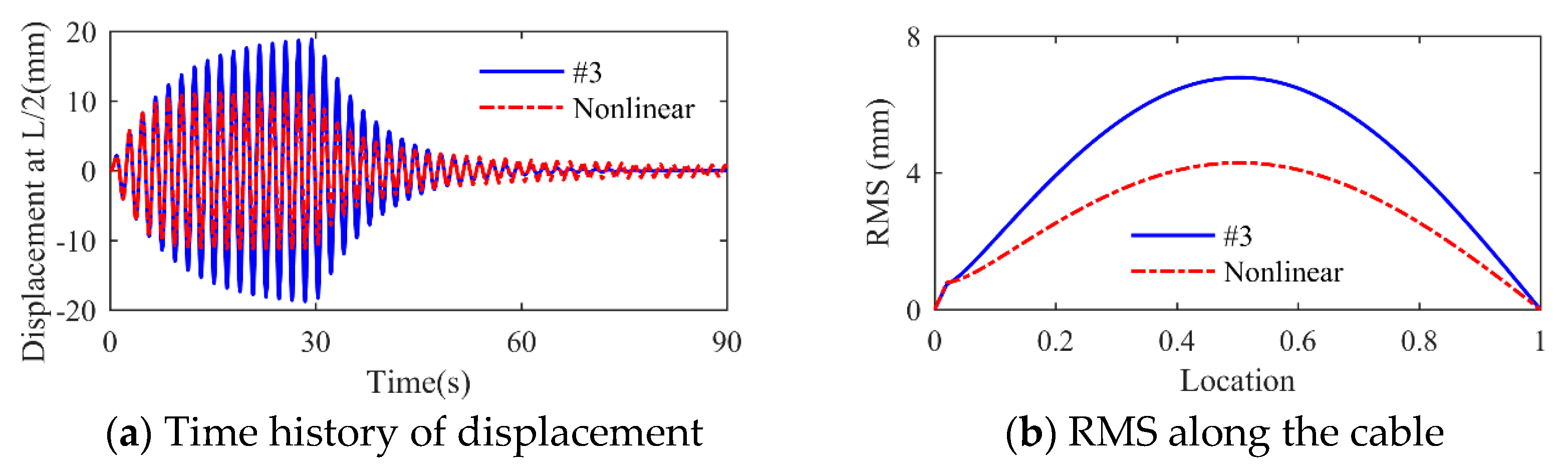
3.4. Simplified Design of Nonlinear Negative-Stiffness Damper for Mitigating Cable Vibration

For nonlinear dampers, it is tough to obtain the exact optimized solutions analytically. Thus, as a pilot study, numerical methods are utilized to explore the control effect of nonlinear negative-stiffness dampers in this section. Based on the aforementioned research, design scheme #3 is adopted as the baseline to compare the effectivity of nonlinear cases. To be relatively fair, the maximum control forces of linear and nonlinear cases are set to be equal. Through experiments and calculations, the damping coefficient c d = 2.33   kNs / m with velocity index α = 0.5 is selected as an example. The negative stiffness and support stiffness are the same to those in scheme #3. According to the configuration of the nonlinear negative-stiffness damper, the level of negative stiffness depends on the stiffness coefficient of the two coil springs and their compression degree (the ratio of the length after compressed to the initial length). For instance, the stiffness coefficient of the two coil springs is k s = 1194.4   kN / m and the compression degree of 0.8 will result in a level of k n = 597.2   kN / m . The weight of the cable is 67.4 × 240 / 1000 16 tons, which is much larger than the total weight of the nonlinear negative-stiffness damper. Therefore, the effect of the weight of the nonlinear negative-stiffness damper is neglected in the study. As can be seen in Figure 13, the maximum control force in scheme #3 are close to that of the nonlinear case under the first-order modal excitation.
Figure 14 further presents the displacement responses of the cable. Compared to design scheme #3, the amplitudes along the entire length of the cable under the nonlinear condition are much smaller. Thus, the nonlinear negative-stiffness damper achieves a better control effect.
Upon changing the exciting frequency, a series of numerical simulations are performed to obtain the results of the first three modes. As listed in Table 4, the maximum control force is maintained almost the same under different modes. However, the root mean square values of displacement response at corresponding nodes experience a significant decrease, from 6.79, 3.27, and 1.69 mm to 4.29, 2.10, and 1.12 mm for the first three modes, respectively.
The reason that the nonlinear damper achieves a better control effect can be determined from the frequency domain analysis of the response. Figure 15 shows the power spectral density at mid-span of the cable under the first mode. In the case of the linear damper in design scheme #3, there is only one peak corresponding to the first modal frequency of the cable. When the nonlinear damper is utilized, the peak value at the first mode decreases relatively, while more peaks appear at other higher modes. These peaks indicate the presence of energy in other modes. However, the frequency of the external excitation is the same as that of the first mode of the cable. It is the nonlinearity of the damper that leads to the energy transferred from the first mode to higher-order modes, such as the third, fifth, seventh modes, etc. Therefore, in addition to energy dissipation, a portion of the cable vibration energy is transferred to high-order modes, resulting in a decrease in the overall displacement response. The power spectral density under other modes exhibits a similar phenomenon. The process of energy transfer will be studied in more detail in the near future.

4. Conclusions

A unified model is established to obtain the equivalent parameters of negative stiffness and damping. Afterward, an optimization process is proposed and verified via numerical simulations. The conclusions obtained are as follows:
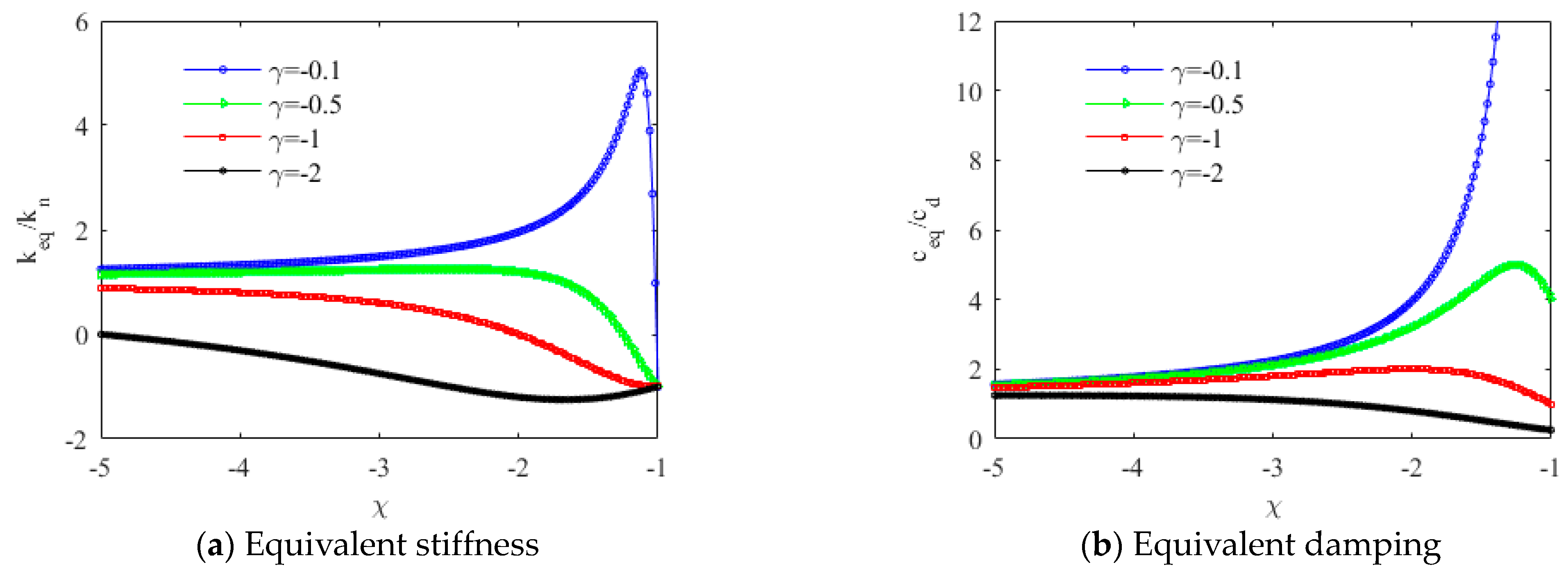
  • A properly flexible support is able to enlarge the equivalent negative stiffness and damping under both linear and nonlinear conditions.
  • An optimization process is developed for multimodal cable vibration. It is sufficient to only consider the highest mode to obtain the optimized size of a negative-stiffness damper and its corresponding support.
  • Nonlinear negative-stiffness dampers have the ability of transferring vibration energy into high-order modes, thereby realizing superior performance in reducing cable vibration.

Author Contributions

Conceptualization, G.L.; methodology, G.L.; software, G.L. and P.Z.; validation, G.L. and P.Z.; formal analysis, P.Z.; supervision, P.Z.; writing—original draft preparation, G.L.; writing—review and editing, G.L., P.Z., T.Y. and Z.L. All authors have read and agreed to the published version of the manuscript.

Funding

This research was funded by Jiangsu Province Innovation and Entrepreneurship Doctoral Program 2022, the National Natural Science Foundation of China (grant no.: 51808175), and the China Postdoctoral Science Foundation (grant no.: 2020T130154).

Data Availability Statement

Data sharing not applicable.

Acknowledgments

The authors greatly appreciate the financial support of the Jiangsu Province Innovation and Entrepreneurship Doctoral Program 2022, the National Natural Science Foundation of China (grant no.: 51808175), and the China Postdoctoral Science Foundation (grant no.: 2020T130154).

Conflicts of Interest

The authors declare no conflict of interest.

References

  1. Wang, H.; Tao, T.; Gao, Y.; Xu, F. Measurement of wind effects on a kilometer-level cable-stayed bridge during typhoon Haikui. J. Struct. Eng. 2018, 144, 04018142. [Google Scholar] [CrossRef]
  2. Ge, C.; Chen, A. Vibration characteristics identification of ultra-long cables of a cable-stayed bridge in normal operation based on half-year monitoring data. Struct. Infrastruct. Eng. 2019, 15, 1567–1582. [Google Scholar] [CrossRef]
  3. Daniotti, N.; Jakobsen, J.B.; Snæbjörnsson, J.; Cheynet, E.; Wang, J. Observations of bridge stay cable vibrations in dry and wet conditions: A case study. J. Sound Vib. 2021, 503, 116106. [Google Scholar] [CrossRef]
  4. Kim, S.; Kim, S.; Kim, H.K. High-mode vortex-induced vibration of stay cables: Monitoring, cause investigation, and mitigation. J. Sound Vib. 2022, 524, 116758. [Google Scholar] [CrossRef]
  5. Nguyen, D.T.; Vo, D.H. Further Explanation on the Excitation Mechanism of Stay Cable Vibration in Dry Conditions. Buildings 2023, 13, 1543. [Google Scholar] [CrossRef]
  6. Zhang, M.J.; Xu, F.Y. Tuned mass damper for self-excited vibration control: Optimization involving nonlinear aeroelastic effect. J. Wind. Eng. Ind. Aerodyn. 2022, 220, 104836. [Google Scholar] [CrossRef]
  7. Chen, L.; Sun, L.; Xu, Y.; Di, F.; Xu, Y.; Wang, L. A comparative study of multi-mode cable vibration control using viscous and viscoelastic dampers through field tests on the Sutong Bridge. Eng. Struct. 2020, 224, 111226. [Google Scholar] [CrossRef]
  8. Lu, L.; Duan, Y.-F.; Spencer, B.F.; Lu, X.; Zhou, Y. Inertial mass damper for mitigating cable vibration. Struct. Control Health Monit. 2017, 24, e1986. [Google Scholar] [CrossRef]
  9. Shi, X.; Zhu, S.Y. Dynamic characteristics of stay cables with inerter dampers. J. Sound Vib. 2018, 423, 287–305. [Google Scholar] [CrossRef]
  10. Wang, Z.H.; Xu, Y.W.; Gao, H.; Chen, Z.Q.; Xu, K.; Zhao, S.B. Vibration control of a stay cable with a rotary electromagnetic inertial mass damper. Smart Struct. Syst. 2019, 23, 627–639. [Google Scholar]
  11. Shi, X.; Shi, W.; Lin, K.; Xing, L.; Zhu, S. Optimal design of tuned inerter dampers with series or parallel stiffness connection for cable vibration control. Struct. Control Health Monit. 2021, 28, e2673. [Google Scholar] [CrossRef]
  12. Gao, H.; Wang, H.; Li, J.; Wang, Z.; Liang, R.; Xu, Z.; Ni, Y. Optimum design of viscous inerter damper targeting multi-mode vibration mitigation of stay cables. Eng. Struct. 2021, 226, 111375. [Google Scholar] [CrossRef]
  13. Li, H.; Liu, M.; Ou, J.P. Negative stiffness characteristics of active and semiactive control systems for stay cables. Struct. Control Health Monit. 2008, 15, 120–142. [Google Scholar] [CrossRef]
  14. Weber, F.; Distl, H. Semi-active damping with negative stiffness for multi-mode cable vibration mitigation: Approximate collocated control solution. Smart Mater. Struct. 2015, 24, 115015. [Google Scholar] [CrossRef]
  15. Xu, Y.-W.; Xu, Z.-D.; Guo, Y.-Q.; Zhou, M.; Zhao, Y.-L.; Yang, Y.; Dai, J.; Zhang, J.; Zhu, C.; Ji, B.-H.; et al. A programmable pseudo negative stiffness control device and its role in stay cable vibration control. Mech. Syst. Signal Process. 2022, 173, 109054. [Google Scholar] [CrossRef]
  16. Pasala, D.T.R.; Sarlis, A.A.; Nagarajaiah, S.; Reinhorn, A.M.; Constantinou, M.C.; Taylor, D. Adaptive negative stiffness: New structural modification approach for seismic protection. J. Struct. Eng. 2013, 139, 1112–1123. [Google Scholar] [CrossRef]
  17. Attary, N.; Symans, M.; Nagarajaiah, S.; Reinhorn, A.M.; Constantinou, M.C.; Sarlis, A.A.; Pasala, D.T.R.; Taylor, D. Performance evaluation of negative stiffness devices for seismic response control of bridge structures via experimental shake table tests. J. Earthq. Eng. 2015, 19, 249–276. [Google Scholar] [CrossRef]
  18. Attary, N.; Symans, M.; Nagarajaiah, S.; Reinhorn, A.M.; Constantinou, M.C.; Sarlis, A.A.; Pasala, D.T.R.; Taylor, D. Numerical simulations of a highway bridge structure employing passive negative stiffness device for seismic protection. Earthq. Eng. Struct. Dyn. 2015, 44, 973–995. [Google Scholar] [CrossRef]
  19. Chen, L.; Sun, L.M.; Nagarajaiah, S. Cable with discrete negative stiffness device and viscous damper: Passive realization and general characteristics. Smart Struct. Syst. 2015, 15, 627–643. [Google Scholar] [CrossRef]
  20. Zhou, P.; Li, H. Modeling and control performance of a negative stiffness damper for suppressing stay cable vibrations. Struct. Control Health Monit. 2016, 23, 764–782. [Google Scholar] [CrossRef]
  21. Zhou, P.; Liu, M.; Xiao, H.G.; Li, H. Feasibility of using a negative stiffness damper to two interconnected stay cables for damping enhancement. Int. J. Struct. Stab. Dyn. 2019, 19, 1950058. [Google Scholar] [CrossRef]
  22. Liu, M.; Zhou, P.; Li, H. Novel self-centering negative stiffness damper based on combination of shape memory alloy and pre-pressed springs. J. Aerosp. Eng. 2018, 31, 04018100. [Google Scholar] [CrossRef]
  23. Shi, X.; Zhu, S.Y. Magnetic negative stiffness dampers. Smart Mater. Struct. 2015, 24, 072002. [Google Scholar] [CrossRef]
  24. Shi, X.; Zhu, S.Y.; Spencer, B.F. Experimental study on passive negative stiffness damper for cable vibration mitigation. J. Eng. Mech. 2017, 143, 04017070. [Google Scholar] [CrossRef]
  25. Shi, X.; Zhu, S.Y.; Nagarajaiah, S. Performance comparison between passive negative stiffness damper and active control in cable vibration mitigation. J. Bridge Eng. 2017, 22, 04017054. [Google Scholar] [CrossRef]
  26. Xu, Y.L.; Zhou, H.J. Damping cable vibration for a cable-stayed bridge using adjustable fluid dampers. J. Sound Vib. 2007, 306, 349–360. [Google Scholar] [CrossRef]
  27. Fournier, J.A.; Cheng, S.H. Impact of damper stiffness and damper support stiffness on the efficiency of a linear viscous damper in controlling stay cable vibrations. J. Bridge Eng. 2014, 19, 04013022. [Google Scholar] [CrossRef]
  28. Huang, Z.; Jones, N.P. Damping of taut-cable systems: Effects of linear elastic spring support. J. Eng. Mech. 2011, 137, 512–518. [Google Scholar] [CrossRef]
  29. Javanbakht, M.; Cheng, S.H.; Ghrib, F. Multimode vibration control of stay cables using optimized negative stiffness damper. Struct. Control Health Monit. 2020, 27, e2503. [Google Scholar] [CrossRef]
  30. Javanbakht, M.; Cheng, S.; Ghrib, F. Impact of support stiffness on the performance of negative stiffness dampers for vibration control of stay cables. Struct. Control Health Monit. 2020, 27, e2610. [Google Scholar] [CrossRef]
  31. Zhou, P.; Liu, M.; Li, H. A passive negative stiffness damper in series with a flexible support: Theoretical and experimental study. Struct. Control Health Monit. 2020, 27, e2594. [Google Scholar] [CrossRef]
  32. Dong, Q.M.; Cheng, S.H. Impact of Damper Stiffness and Damper Support Stiffness on the Performance of a Negative Stiffness Damper in Mitigating Cable Vibrations. J. Bridge Eng. 2021, 26, 04020131. [Google Scholar] [CrossRef]
  33. Chen, L.; Liu, Z.; Zou, Y.; Wang, M.; Nagarajaiah, S.; Sun, F.; Sun, L. Practical negative stiffness device with viscoelastic damper in parallel or series configuration for cable damping improvement. J. Sound Vib. 2023, 560, 117757. [Google Scholar] [CrossRef]
  34. Zhou, P.; Liu, M.; Li, H. Optimized negative stiffness damper with flexible support for stay cables. Struct. Control Health Monit. 2021, 28, e2717. [Google Scholar] [CrossRef]
  35. Chen, W.L.; Li, H.; Ou, J.P.; Li, F.C. Field Monitoring of vortex induced vibration of stay cables of cable-stayed bridge. In Proceedings of the 9th International Symposium on Cable Dynamics, Shanghai, China, 18–20 October 2011; pp. 257–264. [Google Scholar]
Figure 1. Negative-stiffness damper with a support for cable vibration control.
Buildings 13 02620 g001
Figure 2. Mechanical model for the nonlinear stiffness damper with a flexible support.
Buildings 13 02620 g002
Figure 3. Numerical model for the unified model of negative-stiffness damper with supports.
Buildings 13 02620 g003
Figure 4. Hysteresis loops of the damper support system with different levels of support stiffness.
Buildings 13 02620 g004
Figure 5. Curves of equivalent parameters for the damper support system under various levels of damping.
Buildings 13 02620 g005
Figure 6. Test setup of the negative-stiffness damper with different supports.
Buildings 13 02620 g006
Figure 7. Hysteresis loops of nonlinear negative-stiffness damper with different supports.
Buildings 13 02620 g007
Figure 8. Comparison of experiments and theories for equivalent parameters of nonlinear negative-stiffness dampers with flexible supports.
Buildings 13 02620 g008
Figure 9. Stay cable controlled by a nonlinear negative-stiffness damper with a flexible support.
Buildings 13 02620 g009
Figure 10. Variation of additional damping under single-mode vibration for the cable.
Buildings 13 02620 g010
Figure 11. Numerical simulation of the cable with three design schemes of negative-stiffness dampers with supports.
Buildings 13 02620 g011
Figure 12. Additional modal damping ratios under three design schemes.
Buildings 13 02620 g012
Figure 13. Hysteresis loops of negative-stiffness dampers.
Buildings 13 02620 g013
Figure 14. Displacement responses of the cable.
Buildings 13 02620 g014
Figure 15. Comparison of power spectral density at mid-span under the first mode.
Buildings 13 02620 g015
Table 1. Equivalent parameters of the nonlinear negative-stiffness damper under various levels of support stiffness.
Original DamperSupport StiffnessIdentified Equivalent Parameters
kn (N/mm) f 0 (N) k s (N/mm) k e q (N/mm) f e q (N)
−8.7531.0Rigid−8.7531.0
35.7−11.340.3
31.7−12.144.6
24.2−14.048.7
Table 2. Comparison of present work with previous studies on damper support for cable vibrations.
DamperSupportRelated StudiesAnalysis ParametersResults
TypeCharacteristics
Adjustable fluidNonlinear FlexibleXu and Zhou [26] k d > 0 , c d , k s Decreasing support stiffness would reduce the efficiency of a damper positive or zero stiffness.
ViscousLinear FlexibleFournier and Cheng [27] c d , k s
Viscous or frictionLinear and nonlinear FlexibleHuang and Jones [28] c d or F r , k s
Negative stiffness Linear and nonlinearRigid Xu et al. [15], Zhou and Li [20], Zhou et al. [21], Liu et al. [22], Shi and Zhu [23], Shi et al. [24,25] k n < 0 , c d , k s = Support flexibility is not considered.
Negative stiffnessLinearFlexibleJavanbakht et al. [29,30], Dong and Cheng [32] k n < 0 , c d , k s A more flexible support would enhance performance of negative-stiffness damper with proper parameters.
Negative device with viscoelastic damperLinear FlexibleChen et al. [33] k n < 0 , k d > 0 , c d Combining negative device with viscoelastic damper would be efficient but sensitive to parameters.
Negative stiffnessLinear and nonlinearFlexiblePresent work k n < 0 , c d , 0 α 1 , k s A properly flexible support could enlarge equivalent parameters for both linear and nonlinear conditions.
Note: k d is the positive stiffness of a damper, c d is viscous coefficient of the damper, k s is support stiffness, F r is friction threshold, k n is the negative stiffness of a damper, and α is velocity index, indicating the exponential relationship between damping force and velocity.
Table 3. Three design schemes for the first four vibration modes to achieve the required modal damping ratios.
Design SchemesDamping Ratios
ξ j   (j = 1,2,3,4)
Location
a/l
Negative-Stiffness DamperSupport Stiffness
k s (kN/m)
c d (kN s/m) k n (kN/m)
#1 0.8 % 1.5%135.5−298.6Rigid
#2169.3−1194.4
#342.3−597.21194.4
Table 4. Comparison of design scheme #3 and nonlinear case for the first three modes of the cable.
ModeDamper ParametersMaximum Control Force (kN)RMS at Nodes (mm)
LinearNonlinearLinearNonlinearLinearNonlinear
1Design scheme #3 c d = 2.33   kNs / m
α = 0.5
Other parameters unchanged
2.352.486.794.29
21.211.253.272.10
30.830.851.691.12
Disclaimer/Publisher’s Note: The statements, opinions and data contained in all publications are solely those of the individual author(s) and contributor(s) and not of MDPI and/or the editor(s). MDPI and/or the editor(s) disclaim responsibility for any injury to people or property resulting from any ideas, methods, instructions or products referred to in the content.

