1. Introduction
The most significant values of temporary housing are fast assembly and adaptability to different needs and utilization, as well as providing comfort to users. The construction process has to be fast and reliable, starting with an understanding of the users’ needs and ends once all components have been installed. Although modular construction is widely used, the fast and reliable design stage could be significantly improved. It is very important to adopt optimal configurations and dimensions to respond to users’ needs. Recently, research has been oriented towards developing automatic design software based on artificial intelligence to support technicians when it comes to building design [
1,
2]. Since the early 1960s, numerous computer programs have been developed for the automated solution of design problems. The objectives and scope of these programs have varied widely during this period. At first, the main problem was the production facilities layout optimization, to minimize management costs and enhance control [
3]. Recently, architects and interior designers have shown an interest in adopting tools to aid the design of office buildings, hospitals, schools, department stores or residential homes. The diffusive use of the building information modeling (BIM) in the construction sector is giving strong drive to the development of these aided designer tools [
4]. BIM is a process of managing the information model of construction and starting a process capable of verifying a building design and simulating the performance of building constructions. This technology has revolutionized the working practices of architecture, engineering and construction (AEC) [
1]. BIM parametric software is often used to extract quantity takeoff (QTO) from materials and components to organize the production of prefabrication systems. In recent years, building designer software has enabled files to be exported to other software to integrate functions and to implement the building evaluation process with other performance analyses. Total software integration or data exchange between different software file formats is not easy, even now, due to different native platforms. Furthermore, BIM allows for the carrying out of both design analyses and energy performance of buildings. According to Habibi [
2], energy performance is one of the most important steps for creating sustainable buildings and for carrying out reliable lifecycle analysis (LCA). However, the lack of a common data structure could make data exchanges between BIM and LCA difficult [
4].
BIM offers a viable way to improve building efficiency across the entire lifecycle. One of the key challenges identified by Pereira et al. [
5] is the lack of interoperability between BIM and energy analysis tools. This highlights the need for better integration and collaboration to fully realize BIM’s sustainability potential. Biccari et al. [
6] further investigated interoperability, conducting a systematic literature review. Their findings revealed three main strategies for achieving interoperability: scripting, pipelines and model view definitions along with the industry foundation classes schema extension. They stressed the importance of establishing widely accepted strategies and shared guidelines for modeling, particularly in the context of energy evaluations throughout a building’s lifecycle. In order to explore the challenges of BIM-to-BEM interoperability, Kamel and Memari [
7] provided solutions and even demonstrated an alternative tool developed in Python. Their focus was on addressing interoperability issues, particularly in the exchange of building envelope data in energy simulations. Also, Sušnik et al. [
8] investigated discrepancies in data translations between BIM authoring tools and calculation virtual environments for energy and acoustic evaluation, introducing possible solutions to overcome interoperability issues.
In the broader context of sustainable buildings, Fonseca Arenas and Shafique [
9] conducted a systematic literature review that analyzed various methodologies, including BIM, LCA and BEM. They assessed these methodologies based on existing regulations and standards in different countries. Their research underscored how digital tools can facilitate the development of low-carbon technologies and sustainable solutions. Pezeshki et al. [
10] reviewed the development of BEM methodologies and their integration with BIM databases. They covered a wide range of applications, from prediction and estimation to optimal design and evaluation. Their purpose was to determine the extent to which BIM has been adopted as a database in the construction industry for BEM methodologies. Pan et al. [
11] highlighted the growing use of BIM in government sectors globally. They emphasized the importance of using BIM to identify project information needs in accordance with ISO 19650 standards. However, they identified a research deficit, particularly in regions with no set BIM standards, such as Pakistan. In such cases, the authors suggested ISO 19650 as a potential systemic framework.
Regarding BIM and energy performance, Habibi [
2] introduced a strategy that combines building simulation tools and optimization methods. This approach is designed to improve energy efficiency and indoor environmental quality. The study emphasized the value of data integration approaches in improving building performance assessments. Utkucu and Sözer [
12] addressed challenges related to indoor air quality and thermal conditions during building design. They suggested adopting BIM as a basis to tackle these issues by enabling the interchange of analysis methods and simulation technologies. Their study underlined the use of 3D laser scanning to capture accurate geometric information for energy performance evaluations in existing buildings. Similarly, Jung et al. [
13] proposed a method based on 3D laser scanning for defining the level of development (LoD) of in situ BIM for accurate energy performance evaluations in existing buildings. Kamel and Kazemian [
14] explored the energy performance of 3D-printed buildings using BIM. Their research covered various scenarios, including climate zones and concrete types, demonstrating potential energy savings in 3D-printed residential buildings. In the context of data-driven green building design, Zhuang et al. [
15] introduced a performance-integrated BIM framework. This framework optimizes building lifecycle energy efficiency and environmental impact. Through a case study, the authors demonstrated significant improvements in indoor environmental quality and lifecycle cost through optimization. Kim et al. [
16] addressed the challenge of late-stage building energy analysis by introducing an object-based approach to materials in energy modeling. This improves energy analysis accuracy and enables the investigation of energy-saving solutions early in the design stage. Ahmed and Asif [
17] assessed the feasibility of retrofitting existing homes in Saudi Arabia to improve energy efficiency. They employed a BIM-based retrofit framework and energy efficiency measures (EEMs) to evaluate potential energy consumption reductions, highlighting the need for economic incentives for deep energy retrofits.
In terms of optimization, Hosamo et al. [
18] introduced a systematic framework that combines BIM, machine learning, and optimization to predict and optimize building energy performance. This multi-objective optimization model seeks to reduce energy consumption while enhancing indoor thermal comfort. Xu and Liu [
19] used convolutional neural networks and BIM to create a building energy consumption optimization model. They demonstrated how this model can lead to energy savings and improved natural lighting and airflow in buildings. Maglad et al. [
20] explored the potential of BIM in improving energy performance, particularly in academic buildings. They used Autodesk Insight 360 and Green Building Studio for energy analysis and optimization, focusing on enhancing conceptual design and environmental effectiveness. Heydari et al. [
21] addressed the problem of measuring overall carbon emissions in buildings, taking into account both embodied and operational carbon. Their framework quantifies costs and savings while optimizing carbon emissions, providing insights for long-term decision-making.
Concerning automation, Shen and Pan [
22] introduced a framework that combines BIM with machine learning and multi-objective optimization for the automatic prediction and optimization of building energy performance. They emphasized the use of explainable machine learning and advanced algorithms to support sustainable development goals. Adan et al. [
23] described a method for developing 3D semantic thermal models of buildings and converting them into standard BEM formats for energy simulations. This method streamlines the process of producing BEM files from thermal point clouds, making energy performance analyses even easier.
BIM has shown its enormous potential in the management of large private and public civil construction projects. It has made the work of designers easier and more productive due to the possibility of managing very complex construction orders using information processes. From this new process, as a result of the closer connection between the construction and design, the exchange of information and real-time updates are possible. This allows for management of the building in all the phases until its disposal. However, there are more potential uses of BIM that have still not been adequately exploited, such as the possibility of an intuitive program for use by an inexpert user or for advanced customized configuration of housing units. In this research, a semiautomatic procedure of “assisted design” for self-assembling temporary residential houses with high environmental sustainability is proposed. The procedure needs, in any case, human control for some important building functionality decisions; however, it needs to be supported using software tools. In particular, some critical decisions, requiring subjective and specific case-by-case evaluation, are left to the operator, who remains responsible for the design. The developed procedure allows for the support of a nonexpert user in the configuration of the housing module, using base elements, and assists them until the energy verification and environmental impact based on the place of installation has been completed. This method allows for even less experienced users to approach BIM. This was made possible thanks to the use of Dynamo
®, which is an open-source graphical programming interface that is part of Revit
® and allows for the management of specific parameters by using programming code blocks. Different from Ezzeddine et al. [
24], in which the automatic generative of building was made using Unity software, which is a real-time 3D game platform, in this research, a Dynamo
® script was written to manage the line-based family of the temporary house, the generation of the component schedule and the export of an Excel
® file. Therefore, the nonexpert user only has to compile an Excel
® file and run the Dynamo
® script. It is fundamental to provide fast answers to people’s needs, especially in emergency situations such as earthquakes, pandemics, immigration, or other painful situations that have unfortunately occurred around the world in recent years. The informatization of the procedure makes it possible to share the solution with manufacturing companies for the supply of construction elements, which will then be immediately available to the user for assembly. The time taken to design a traditional building is a small percentage when compared to its entire lifecycle. However, if the building to be built has a strong temporal character and a very limited time availability, a quick response is needed. Therefore, it is necessary to decrease the amount of planning time needed to the advantage of the immediate availability of the building. This article is structured as follows:
Section 1 is devoted to the problem statement and aim of the present work. In
Section 2, a sustainable, modular temporary house is described. In the
Section 3, the developed procedure is described; the user needs, the layout definition and the BIM modeling generation are described, respectively, in
Section 3.1 and
Section 3.2. In
Section 4, a specific case study is carried out to illustrate the procedure proposed and to highlight its strengths and weakness. A five-module temporary house represents our case study, generated by means of the procedure proposed. Energy analysis and environmental impact analysis are described, respectively, in
Section 4.1 and
Section 4.2. The obtained results are then analyzed and discussed and are reported in
Section 5. Finally,
Section 6 is devoted to conclusions and future research outlooks.
3. A Method for the Semiautomatic Design of Temporary Housing
The temporary house construction requires a high level of design–production integration, in particular the design of functional space and that of the structure and its elements, but also plans the processes by which a building is manufactured, transported and installed [
28]. In this study, components of the temporary house were entirely modeled into a parametric software package called BIM Autodesk Revit
® 2022 in order to create a semiautomatic procedure. The rules that make up the joints of the components were written into Dynamo
® software (Version. 2.12), which allows for the quantities to be extracted automatically. In the end, as can be seen in
Figure 3, the digital model is exported to DesignBuilder
® software, allowing for an LCA to be performed. In detail, the procedure proposed includes the five steps listed below:
In the first step, starting from the user’s need, we defined the layout complete with the selection of the plant facilities of the temporary house.
The second step is performed by means of a semiautomated process used to acquire the parametric information of the previous step—the BIM model.
The BIM model allows for obtaining a complete list of the materials, components and plants in the third step, making material supply easier.
In the fourth step, the BIM model is imported to energy platform software that supports the designer in carrying out energy analysis and thermal performance optimization.
In the last, fifth step, an online lifecycle analysis platform enables the BEM import, developed in the previous step, to support the designer in an environmental global impact analysis of the temporary building.
3.1. User Needs and Layout Definition
The temporary house can be used in a variety of applications due to its high flexibility and adaptability, which makes it suitable for different contexts of use. The ease and speed of assembly, the modularity of the system and the sustainability of the materials are among the characteristics that allow for a wide range of uses. Based on a detailed analysis, several possible utilizations were examined and grouped into four main categories, as shown in
Figure 4.
The definition of the temporary house layout starts from the identification of the user’s needs and the performance characteristics required of the technological system. A set of analysis criteria were determined, based on which a semi-guided procedure was set up that allows for even less experienced users to proceed through the design of the module and quickly and easily attain the project configuration.
The following design criteria were used: recipient, activity, time of use, size, configuration, facilities.
Specifically, with regard to the recipient, five options are provided. The temporary house can be used by a single individual, two people, a family (in this case, specify the number of members), a small group of people (maximum five people), a large group of people (greater than six).
Subsequently, the main activity performed within the building can be selected. Based on this criterion, seven alternatives have been identified, leading to the following activities: living, emergency, shelter, work, entertainment, studying, ancillary services.
The usage time is one of the most important elements in defining the characteristics of the house. Three possible time-of-use bands have been envisaged, divided into short duration, if the temporary house is used for a period of one week at most; medium duration, referring to a time of use ranging from two to four weeks; and long duration, for cases in which the time of use is more than a month [
27]. The dimension of the house can be defined depending on the type and number of recipients, the activity carried out and the time of use. The dimension refers to four sizes: S, M, L and XL.
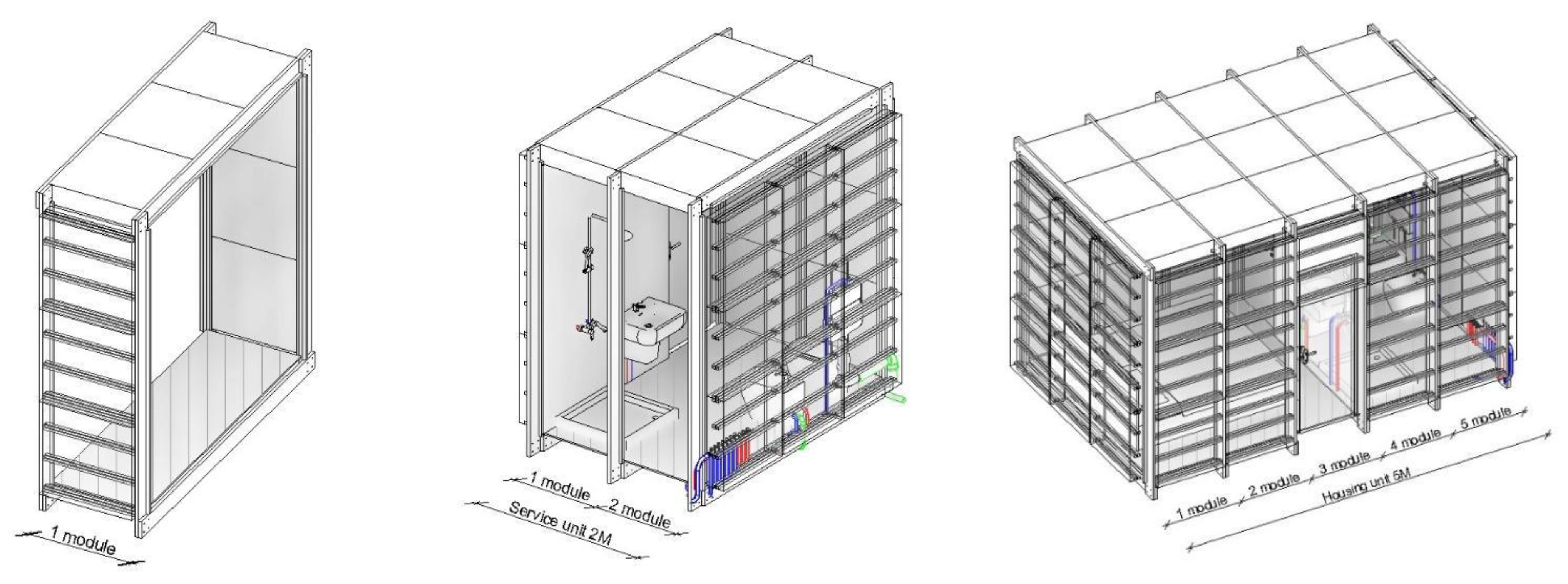
The single 1M module is the structurally independent basic unit. However, to obtain a minimally functionally independent unit, the use of at least a 2M is necessary. This is the minimum functional unit, corresponding to an area of 4.86 m2. It is labeled as size S (small) and can only be used as a technological unit for services (for example, a toilet). The M (medium) size includes modules made by assembling 3 to 5M, with a surface ranging from 7.29 to 12.15 m2. The minimum housing unit requires a 5M with a surface area that can accommodate a bed and a bathroom and is designed as an emergency shelter for a single user. The large size requires the use of a higher number of base modules (6 to 10 M) and provides a usable area ranging from 14.58 to 24.3 m2. Finally, the extra-large size can be used in cases where more than 10M is required and provides a floor area greater than 24.3 m2. The geometric configuration has been standardized with reference to three shapes. The simplest solution is a quadrilateral, which is also the only one possible for the smaller sizes (S and M). A slightly more articulated level is based on the construction of a polygon (for example, L-shaped). More variation in the plan can be achieved by selecting the complex shape, which can be used for L and XL configurations. The described approach allows for easy integration with other design criteria.
Figure 5 shows some examples of spatial solutions.
The design procedure is completed with the selection of plant facilities. The temporary house can be equipped with various technological systems, which include electrical system, water–sanitary system, ventilation, heating and/or cooling, photovoltaics and internet connection. Plant equipment will vary depending on the activity performed and the time of use, as well as the climatic conditions of the location where the houses are installed.
Figure 6 explains the analysis criteria adopted in the assisted design.
From the combination of the illustrated criteria, abacuses of uses have been prepared, divided into categories, which can support the user during the design phase (
Appendix A). The tables contain 63 solutions (labeled “1a” to “4n”).
Those reported in the tabs are some of the possible solutions, developed based on the analysis of the occupants’ needs. However, in addition to the “catalog” combinations, the user can create his or her own custom temporary house by interacting with the dialog box, allowing anyone to tailor-make their own product. The design can be carried out using a dialog box created in Excel
®, in which the user, who is not a BIM expert, in a simple and intuitive way, can easily select the alternatives, shown in
Appendix A (Tab 1, Tab 2, Tab 3, Tab 4), which they consider the most appropriate for their needs and personal preferences. The file thus compiled, provided as an input to Revit
® by Dynamo
®, allows for the generation of the 3D design model, so as to provide the user with an overview of the final building.
3.2. BIM Modeling Generation
In the acronym BIM, the “I” of “Information” acquires a significant role. In a traditional construction process, information is often lost during the exchange between one discipline and another. Using this new process, all the information is now inserted into the 3D model and associated with it as an “informative attribute”. The 3D model becomes the informative attribute container where all the actors find information. BIM consists of intelligent structural components, which include data attributes and parametric rules for each object [
29]. Consequently, the software used in the process acquires a decisive role. Interoperability enables model sharing and linking data between different operators, and BIM applications ensure data consistency [
30]. In recent years, there has been a rapid development of software dedicated to architectural modeling and, above all, to their ability to connect to other programs via plugins. The ISO (International Organization for Standardization) has drafted an international standard relating to BIM methodology. The CEN (European Committee for Standardization) has also adopted ISO 19650. In Italy, UNI 11337 (consisting of parts 1 to 10) regulates the construction process according to the new BIM methodology. Furthermore, starting from January 2018, DM 560/17, the so-called “Baratono” decree, updated from DM 312/2021, introduces the obligation of BIM in public procurement, and from 1 January 2023, it is obligatory for all new constructions and/or works on existing buildings for an amount based on or over the threshold referred to in Article 35 of the Public Procurement Code. The legislation refers to the creation of new specialized professionals who have very specific roles within the BIM process. It refers to the role of BIM specialists by discipline; to the BIM coordinator, who directs the various BIM Specialists; and to the BIM manager, who manages the project according to the BIM methodology. In this research, we also want to assign a role to the client making a choice regarding the temporary house based on the use to be made of it, how many users the building has to host, how long it is used and the equipment required. Subsequently, as the workflow shows in
Figure 3, the automation process recreates the temporary house (or different conformation of it), which contains all the specifics required during the choice, for the nonexpert user.
4. Case Study: A Five-Module Temporary House
The semi-automated process guides the user, starting from the compilation of an Excel
® sheet, to software Autodesk Revit
® between the 3D modeling of the house, which has all the parametric information (shared parameters) needed, with the help of the Dynamo
® script. It also provides an Excel
® sheet as a result, containing all the components needed to construct the building. At the end of the process, it is possible to export a gbXML file, which is useful for conducting energy analysis. The first phase of this research involves the geometric modeling of the elements constituting the building module, that is, the multilayer agglomerated cork panel and structural elements. Autodesk Revit
® 2022 organizes the elements by classifying them within specific categories (wall, curtain wall, column, door, windows, etc.). Some parts have necessarily been modeled as a “generic model” (
Figure 7).
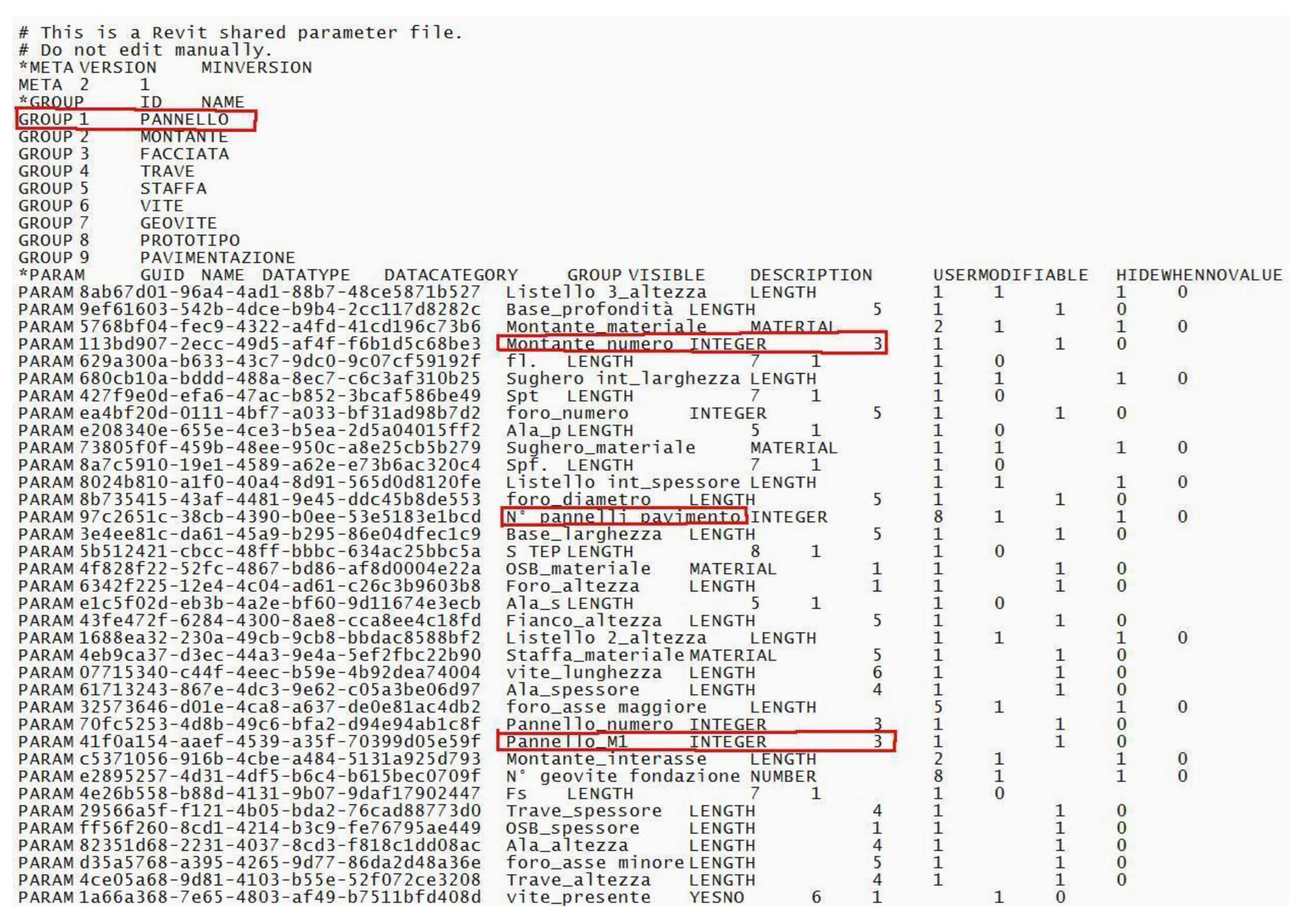
Each modeling is parameterized, which means that a parameter is associated with the corresponding geometric element. The software thus generates a text file containing all the shared parameters (
Figure 8).
It is essential to set up the shared parameters in order to connect the elements together and to organize the information [
31] useful for the Dynamo script. The shared parameters allow for management of the information via the schedule and for use in formulas (
Figure 9).
Thanks to the use of these formulas, a rule is created for automatic drawing of the 3D model of the temporary house. All the modular elements forming the case study were inserted within a “line-based family” category, namely an object that develops simply by drawing a line. All the elements were grouped together in “model groups”, making it possible to reproduce them in series by controlling them through a matrix to which a rule is inserted (
Figure 10). The strength of the “line-based family” allows a nonexpert user to form their own complex geometries simply by drawing a line with the same simplicity as drawing on a sheet of paper.
Creating this rule and a “generative model”, starting from drawing, a line allows even the less experienced user to create their own house in an easy and intuitive way. When the script is started, the Excel
® file containing the multiple choice of the temporary house is opened automatically (
Figure 11). This helps the user to make choices about the house that best suits their needs. In the end, the choice generates the defined length of the building, which is used by the Dynamo
® script to generate the 3D model in Revit
® automatically.
The nonexpert user is only required to click on family instances in Revit
® and to press play for the Dynamo script. The script uses the block “Select Model Element” and has been organized in order to fix the origin of the line at coordinates x = 0, y = 0, z = 0 of the project by using the Dynamo Block named “Point.Origin”. Then the direction of the line is oriented along the X-axis using the block “Vector.XAxis” (
Figure 12). Finally, a node of the script acquires the length of development of the temporary house using the connection to the Excel
® file. The line-based family is generated using the line sets in the block “Line.ByStartPointDirectionLength”.
After the first part of the script, which manages the geometry of the family, the software automatically continues with the automatic generation of a schedule containing all the components of the house (
Figure 13).
A node of the script is in fact dedicated to the extraction of the parameters initially inserted in the family and now useful for counting the elements present, the extrapolation of their dimensions, their material and more (
Figure 8). The last step exports the schedule to an Excel
® sheet. All the block nodes are native of Dynamo
® for Revit 2022, no package was downloaded nor was a personal code block created, in order to make the use of this step more friendly for all users seeking to create their personal temporary house.
Figure 14 shows the result in Revit
® of the 3D model of the house generated using Dynamo
® from the input of the Excel
® file.
This makes it even easier to construct the building. Generative design refers to any design practice where the designer uses a system, such as a computer program, to produce the solution for the design problem with some level of autonomy [
32]. Differently from Ghannad and Lee [
33], who proposed a generative design system offering the module configurator, which helps designers generate and evaluate multiple module configuration alternatives, in this research, the automatic generative modeling process can be repeated by a nonexpert user several times in order to obtain different configurations of their module house using an iterative process.
4.1. Energy Analysis
Once the desired prototype has been generated, it can be exported to energy analysis software to carry out further checks and use it in software for BEM analysis [
34]. As “Technical Report for BIM-BEM Workflow” eported, rather than being a multipurpose, multi-serialized schema like IFC, gbXML focuses solely on exchanging information between BIM software platforms for building energy modeling and analysis processes. By using the DesignBuilder
® plugin in Revit
®, it is possible to export the volume and the rooms into the software (
Figure 15). Since both the stratigraphy and the characteristics of the vertical and horizontal partitions are known from previous studies [
27], it is easy to analyze the energy performance of the temporary house. The software allows for customized configuration of the stratigraphy and heat transmission. Once the partitions have been loaded into the DesignBuilder
® software, it is possible to export the customized library [
35]. This data exchange needs the operator’s support because this procedure is not completely automatic, as it is necessary to link the model BIM material database to the DesignBuilder
® library. So, when the user needs to carry out the energy analyses of the house, they can easily load the previously supplied library [
1].
After loading the stratigraphy, the use of the temporary house, the occupants and the systems installed are indicated to perform BEM analyses by leveraging EnergyPlus
® [
36]. It is, therefore, also possible for a nonexpert user to conduct energy analyses. It is important to locate the house in the place where it will be built to analyze the energy performance relating to the climate and the place, the orientation and the time of year. Using the settings, it is possible to carry out an hourly, daily, monthly or whole-year analysis.
The characteristics of the cork panel can vary according to climatic conditions under which the building is expected to operate. By changing the thickness of the insulating layer, it is possible to adapt the thermal performance to the minimum requirements set by regulation. For example, in previous studies conducted in a location with a Mediterranean climate, a panel with a thermal transmittance of 0.34 W/m
2 K was adopted [
27]. Simulations conducted under free-floating conditions (without an air conditioning system) have demonstrated a good ability of the envelope to maintain internal comfort conditions, with air temperatures in the range of between 20–26 °C and 36% of the hours evaluated on an annual basis. In particular, the positive behavior of the envelope in the summer period is highlighted. By using a phase change material layer with a 21 °C melting point (PCM21) in the panel, it is possible to achieve approximately 90% of hours with temperatures in the comfort range in the month of June (
Figure 16) [
36]. In the presence of an air conditioning system, an annual energy consumption of about 35.4 kWh/m
2 is estimated, approximately 45% lower than a standard prefabricated module evaluated under the same use conditions (
Figure 17) [
27]. The integration of a photovoltaic system and a storage battery could make the module almost energetically self-sufficient [
36].
An additional plugin in DesignBuilder® allows for further analyses to be performed, related to lifecycle assessment, by exporting the model to the specific LCA software. To develop a correct LCA, it is necessary to request the operator to integrate the data with other more specific information such as the distance the materials have to be transported, energy costs, etc. Although the plugin allows DesignBuilder® to export the geometric data of the building, the designers have to make some important choices relating to the environmental footprint of the used materials.
4.2. Environmental Impact Analysis
The environmental impact of a building starts with the production of its components and ends with the removal and/or reuse of the building rubble. Energy is used for the environmental control of the building and pollutants are emitted externally during its use. The total environmental impact has to be evaluated with reference to the site’s local characteristics that condition the energy used to control the indoor temperature and the distance of transporting materials [
37]. The last stage of the procedure proposed in this study is the LCA of the temporary housing. An LCA was conducted by means of the One Click LCA (OCL) online platform. One Click LCA is an online software platform for the lifecycle assessment of buildings or infrastructures. It includes a large materials EPD (environmental product declaration) database in this field and is offered as a cloud service. Furthermore, it is complemented by an API that includes many of its functionalities, so third-party applications can set up and run an LCA from their own user interface (UI). The API of One Click LCA has already been implemented in plugins for applications such as Autodesk Revit and DesignBuilder. Although not all the functionalities of One Click LCA are included in the API, it includes a method for exporting material data into their web platform to run the LCA there and access all functionalities such as input materials verifications, advanced LCA, graphic analysis of results or embodied energy comparison with benchmark projects [
38]. Generally, the key point of an LCA is the quality and accuracy of input data. The OCL method provides two tools to help users with this. The first tool is the Plausibility Checker, which checks the plausibility of material inputs. The second is Completeness Checker, which checks if all required elements are in place for the applicable standard or certification in question. The OCL database was developed to guarantee the following principles:
o Availability: any users can integrate this data as their private LCA datasets.
o Plausibility: in accordance with EN 15978, any market-based LCA data has to satisfy the OCL data.
o Consistency: in accordance with EN 15978, if data include biogenic carbon storage, they are homogenized to ensure consistency of calculations.
o Representativeness: all data are comprehensively classified based on geographical and time representativeness,
o Transparency: the data are enriched with metadata and information, allowing users to understand the datapoint and its quality better.
The One Click LCA platform provides over 100 different tools for calculating environmental impacts according to different standards and certifications. These tools operate independently of each other and provide different compliance results. Each tool sets the requirements for the LCA data it allows to be used, the modelling scope, lifecycle modules used in calculations and detailed rules used for applying them, as well as formats and methods for reporting the results. Energy analysis was performed for the building location in the previous process stage by means of DesignBuilder software. This software comes with a native integration, and it allows users to transfer the energy model directly to One Click LCA for additional materials analyses, using its materials database to obtain a true picture of the carbon and LCA performance [
39]. The building material quantities are directly supplied from Revit
® (which uses the volume estimating capacity). These quantities were directly input into the One Click LCA (cloud based) software through an energy model integration process. The environmental impact analyses are carried out with reference to specified material and construction method typology using the environmental product declaration (EPD) database files and the transport distance of the materials with reference to the period that the building is in use [
40]. The integration of this software is not yet fully complete, but it allows for a rapid environmental analysis procedure starting from the geometry and volume of the building to the thermal performance on the expected site installation with limited intervention from designers. DesignBuilder software provides a tool to export the geometric building model as a Green Building XML file (gbXML). This file format is an open schema developed to facilitate the transfer of building data, stored in the BIM, to the sustainable building design tools. By means of the One Click LCA software tool, the model containing the building geometric data necessary to include in the LCA is defined. The designer has to choose the correct building materials in the software database in order to conduct a suitable environmental impact analysis. The environmental analysis results for this case study, with a time use of 5 years, highlighted that the electricity use for indoor temperature control [
41] has a higher impact than all of the others (
Figure 18). To improve the environmental impact, it is possible to return to the first stage and choose a better thermal performance solution and repeat the procedure in an iterative way [
42].
5. Results and Discussion
In this research, we propose the semi-guided creation of a sustainable temporary house by means of a BIM procedure. Differing from generative design procedures, the proposed prototype has well-defined construction characteristics that allow for the creation of rules through the use of parameters. Revit® is a parametric BIM software package that allows for the creation of a digital model as a container of information, providing information that can be searched and processed. The insertion of the parameters and the rules that manage the conformation of the temporary house can be managed using an additional software package, Dynamo®, which automates the process. Having it managed using the line-based family and consequently with a Dynamo script makes the configuration of the temporary house automatic. It thus becomes simple for a nonexpert user to autonomously generate the most suitable house for them, starting from an Excel file. Once the model has been generated and the quantities to build it have been obtained, it is necessary to analyze the context in which it will be built. Revit® software has a direct exchange link with energy analysis software for generating a BEM. This part of the process must be managed by an expert user who, however, has access to the customized library that contains the performance characteristics of the stratigraphy. The sustainability characteristic of the prototype components is underlined in the LCA. The case study highlighted the suitability of the proposed procedure in order to show the reliability of the Dynamo script to generate a complex design with only a few steps, allowing the designer to focus on strategic points such as the users’ needs, energy performance and the environmental sustainability of the temporary house. It showed the high reliability of the proposed method, allowing the designer to concentrate only on the strategic problems of the design in order to carry out, rapidly, the architectural model of the temporary house and speed up the sustainability assessment of the temporary housing. This could be significantly helpful to government administrations, as it could provide an efficacious answer to an accommodation emergency. It is important to highlight that designer intervention becomes fundamental in carrying out a suitable design. It is the only responsible strategic decision to obtain the best solution for the users’ community needs. The decision process in building design is very complex; in this process, numerous elements are involved, such as the designer’s experience, the local context, the budget and others. The proposed method, for these reasons, provides three specific intervention points for the designer where human control is required. The first human control point is related to the choice of the best spatial configuration of the temporary house. In this stage, using the Excel procedure, some temporary housing layout solutions suitable for the user’s needs are proposed. The operator is asked to choose the best solution, for example, in relation to the landscape or the local building tradition. The second human control point is necessary to define the building energy model. In fact, the choice of material and the stratigraphy of the building envelope are highly dependent on local weather conditions, the season of use and the time period of use. The third and final human control point is foreseen to allow the designer to choose the construction materials according to their different environmental impact in each life phase in relation to the characteristics of the installation site such as the transport distance, the production impact, disposal or preference for one aspect over another.

 ,
, 