Abstract
The reliable bond of CFRP to heat-damaged concrete is fundamental to ensuring cooperative working when the CFRP is applied for strengthening fire-damaged concrete structures. In this paper, the bond performance of hybrid-bonded (HB) CFRP to a heat-damaged concrete surface was investigated by using single shear tests. The concrete blocks were initially heat-damaged to temperatures of 100 °C, 200 °C, 300 °C, and 400 °C. The heat-damaged blocks were subsequently bonded with CFRP using the HB technique. The primary experiment parameters were the exposure temperature, the number of mechanical fasteners, and the bonded layers of CFRP. The test results show that the external-bonded (EB) and HB-CFRP joints with concrete exposed to a temperature of 400 °C were prone to fail with concrete shear-tension due to the decreased shear strength of concrete at high temperatures. The EB- and HB-CFRP joints with heat-damaged concrete anchored with no more than three fasteners present a higher bond than the reference joints with unheated concrete, while the HB-CFRP joints anchored with three fasteners provide a decreased bond capacity with the increase in exposure temperature. The utilization rate of single-layer CFRP joints with unheated concrete increased by 57.9%, 139.5%, and 136.8% with the mechanical fasteners in numbers of one, two, and three compared with the reference specimen. Accordingly, the bond capacity increased by 111.8%, 128.4%, and 186.7%. Finally, a model was proposed to estimate the bond strength of HB-CFRP joints with heat-damaged concrete.
1. Introduction
Concrete structures may experience short-term exposure to high temperatures, such as fire disaster, during their service life. This draws attention to investigating the residual load-carrying capacities of fire-damaged concrete elements in order to make decisions on future repair or strengthening actions to ensure safety [1,2,3,4,5]. Some research efforts carried out so far on this topic are outlined in the following. Chanachai et al. [1] investigated the flexural response of reinforcement concrete (RC) T-beams after exposure to elevated temperatures of 700 °C and 900 °C for 3 h and then being cooled in air. The test results showed that the sustained loading decreased the stiffness, ductility, and the even strength of the fire-damaged beams. Another experimental study on the post-fire seismic behaviors of concrete stub columns showed that the shear strength and the accumulated hysteretic energy dissipation of the specimens decreases by 41.2% and 46.2% after 120 min of fire exposure on four faces [3]. A study of Liu et al. [5] indicated that the ultimate load, energy dissipation, and initial stiffness of post-fire RC shear wall reduced by 15.8%, 59.2% and 51.8%, respectively. Moreover, the combined action of elevated temperatures and axial load resulted in more energy dissipation reduction than the individual fire exposure. In general, the elevated fire exposure had a detrimental effect on the strength, stiffness, and ductility of RC elements, while the moderate fire caused minor damage to concrete members. Therefore, fire-damaged RC structures can be kept to use with adequate repair and retrofitting when fire occurs in a part of the structure or for a short duration [6,7].
In recent years, carbon-fiber-reinforced polymer (CFRP) becomes widely used for strengthening deteriorated concrete members due to its higher tensile strength, light weight, corrosion resistance, and ease of installation [8,9,10,11,12]. Researchers [13,14,15] have investigated the performance of CFRP-strengthened fire-damaged RC columns for restoring the axial strength, stiffness, and displacement ductility using CFRP confinement. It was found that CFRP retrofitting could restore the axial strength and ductility, but could not fully restore the axial stiffness of columns suffering from a combination of fire and axial compression. For heat-damaged RC beams, the strength of external-bonded CFRP (EB-CFRP) could reach and even exceed that of the reference RC specimen [16,17,18]. But an issue existed in that most of the failure modes of EB-CFRP prematurely debonded rather than the fracture of CFRP itself [19,20,21]. Researchers were aware of the fact that the debonding of CFRP leads to premature failure, causing the issue of the insufficient utilization of the high strength of CFRP [22,23,24,25]. This promotes a lot of attempts that employ appropriate techniques to decrease the possibility of the debonding failures. Among them, a strengthening technique of mechanically fastened FRP (MF-FRP) was developed to fasten the FRP strips to the concrete by using mechanical fasteners that were pre-shotted or screwed directly into the concrete [26,27,28]. The investigations of the MF-FRP-strengthened beams indicated that not only did the yield and ultimate strength of beams increase, but the failure mode was also improved to effectively avoid the FRP debonding. However, the MF-FRP strengthening technique had some deficiencies, for example, instant cracks during the shot fastening progress resulted in the eventual pullout of the fasteners off the concrete, or the screws may cut through the FRP at the eventual failure.
Based on the existing research, a new technique named hybrid-bonded FRP (HB-FRP) proved to be a relatively more effective method combining the EB-FRP system with the MF-FRP system [29,30]. It was found that the ultimate bearing capacity of the HB-FRP strengthened RC beam was 7.5 times that of the conventional EB-FRP strengthened RC beam, thus successfully avoiding the intermediate crack-induced debonding failure [30]. Continuously, a finite element model was developed to evaluate the bond strength of the HB-FRP retrofitted concrete beams, while the accuracy of models was demonstrated by comparisons between the predictions of the models and the test results [31]. The experimental studies and numerical analyses of the bond between HB-FRP and concrete indicated that the ultimate strength, the FRP utilization, and the ductility significantly increased with the increase in the applied torque on steel bolts to increase the interfacial friction, and the ultimate strength linearly increased to approach an asymptotical upper limit with the number of mechanical fasteners [32,33,34,35,36].
Therefore, the literature review indicates that almost no studies have been carried out on the bond behavior between HB-FRP and heat-damaged concrete, although the latent possibility existed on the bond properties of HB-FRP with heat-damaged concrete affected by exposure to elevated temperatures [19,20,21]. This promotes the study of the bond behavior between HB-FRP and heat-damaged concrete, which could provide a reliable design of HB-FRP applied to strengthen fire- or heat-damaged RC structures.
2. Experimental Program
2.1. Details of Test Specimens
A total of 76 single-shear CFRP-to-concrete joints were prepared; 2 of them were identical as a group. A total of 28 groups were HB-CFRP joints while the remaining were EB-CFRP joints serving as references. The experimental parameters included the exposure temperatures of concrete blocks, the number of mechanical fasteners, and the layers of bonded CFRP.
As demonstrated in the literature, the compressive strength was significantly decreased when the temperature of concrete was over 500 °C [37,38], at which the heated concrete was removed before concrete structures were strengthened. Hence, five exposure temperatures, including ambient, 100 °C, 200 °C, 300 °C, and 400 °C, were adopted and labeled as TA, T1, T2, T3, and T4, respectively. The number of mechanical fasteners was 1, 2, and 3, respectively. And they were labeled as N1, N2, and N3. The bonded CFRP layers were 1 or 2 and labeled as C1 and C2. However, three fasteners could not be fastened for concrete blocks after exposure to 400 °C because of concrete splitting failure during the drilling holes process.
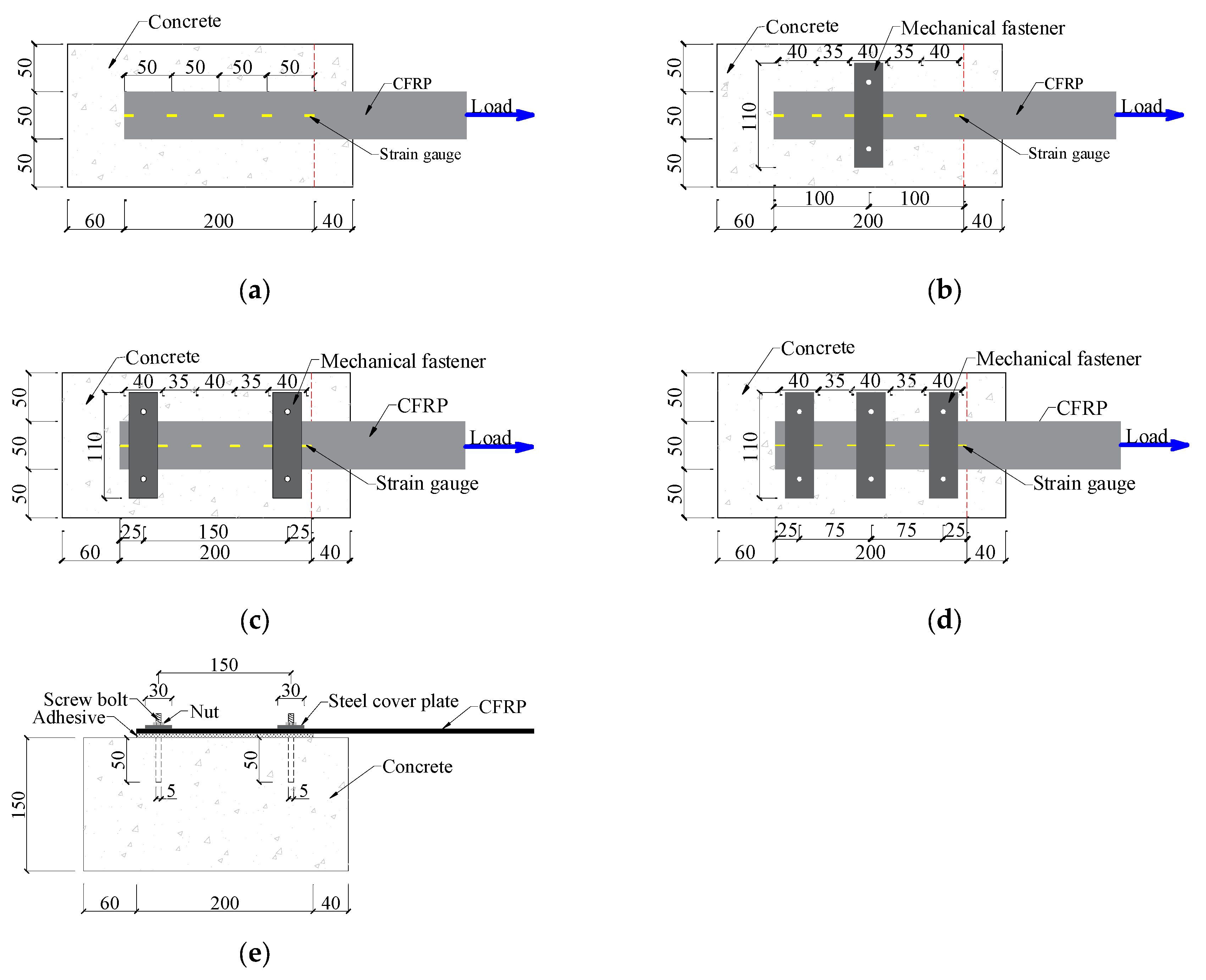
As illustrated in Figure 1, the CFRP sheet was bonded on the surface of a concrete block with a dimension of 150 mm × 150 mm × 300 mm. The bond width and length of CFRP sheet were 50 mm and 200 mm, respectively. To prevent stress concentration at the load end of the specimen, a 40 mm non-bonded segment was reserved near the loading end. The frictional resistance at the debonding interface can be enhanced with an improved mechanical fastening system [39], so this system was adopted. The mechanical fastener consisted of a steel cover plate, two screw bolts, and nuts, as illustrated in Figure 1e. The steel cover plate used in this study was 110 mm long, 30 mm wide, and 5 mm thick. Two screw bolts of 5 mm diameter were used with each mechanical fastener.
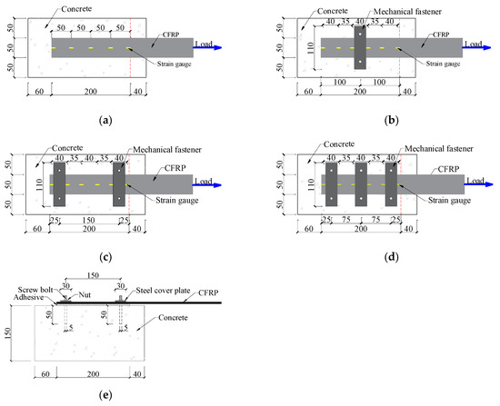
Figure 1.
Test specimen for: (a) EB series, (b) HBN1 series, (c) HBN2 series, (d) HBN3 series, and (e) HBN2 series (side view).
Concrete blocks were heated with a heating rate of 20 °C/min to 100 °C, 200 °C, 300 °C, and 400 °C, and then they were kept for 2 h inside the electrical furnace. After that, the heated blocks were cooled in the furnace by opening the door. The CFRP sheets were bonded to concrete blocks using the HB technique as follows. Firstly, the bond surface of each concrete block was roughened using a hand-grinding blade until the aggregate became clear. Secondly, as illustrated in Figure 1e, the holes, with diameters of 8 mm and 50 mm deep on the pre-marked locations of concrete, were drilled with a drilling bit. Two predrilled holes were required for each mechanical fastener. The dust inside the holes and on the surface of concrete was cleaned using a blower. After that, the CFRP sheet was bonded on the surface of the concrete using a wet lay-up process. When the adhesive-bonded CFRP on the concrete surface hardened, some epoxy was filled into the predrilled holes and the bolts were implanted in these holes, the steel cover plate was bonded on the surface of a CFRP sheet using epoxy resin adhesive. Finally, a torque of 5 N·m was applied on the nut using a torque wrench when the epoxy hardened.
2.2. Materials
The concrete mixture was designed for a target cubic compressive strength of 50 MPa after a standard curing age of 28 days. The tested value of cubic compressive strength was 53.2 MPa. After exposure to high temperatures of 100 °C, 200 °C, 300 °C, and 400 °C for 2 h inside the electrical furnace, the compressive strengths of concrete cube were 49.5 MPa, 42.4 Mpa, 40.1 Mpa, and 35.8 MPa, respectively.
The tested tensile strength, modulus of elasticity, and ultimate strain of the CFRP sheet were 2613 MPa, 245 GPa, and 1.76%, respectively. The tensile strength, modulus of elasticity, and elongation of the adhesive were 43.7 MPa, 2612 MPa, and 1.54%, respectively. The tensile strength of the bolt used for the mechanical fasteners was 400 MPa with a yield strength of 320 MPa.
2.3. Test Setup and Instruments
The test setup is shown in Figure 2. The free end of the concrete block was firmly fixed to the top of a steel beam using a clamping system. The tensile load applied to the CFRP sheet increased monotonically until failure. Two linear variable displacement transducers (LVDTs) were parallelly installed at the loaded and free ends of the joint to measure the bond slip between the CFRP and concrete. The strain gauges were pasted on the CFRP sheet, as illustrated in Figure 2, in order to monitor the CFRP strains. The readings from the LVDTs, the strain gauge, and load transducers were recorded with a data acquisition instrument connected to the computer.
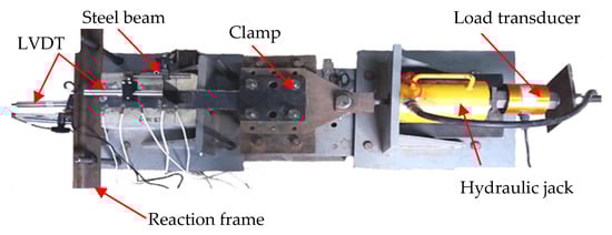
Figure 2.
Test setup.
3. Results and Discussions
3.1. Failure Patterns
The main test results are summarized in Table 1. Where Pu is the ultimate load for the specimens, D denotes the failure of the CFRP debonding, CF denotes the failure of the CFRP fracture, BF denotes the failure of the bolt fracture, and CST denotes the shear-tension failure of the concrete. The utilization rate is calculated with the measured maximum CFRP strain at the bonding interface divided by the CFRP tensile rupture strain.

Table 1.
Summary of test results.
3.1.1. EB Specimens
The failure of the EB-CFRP joints was characterized using the CFRP sheet bonded with a thin layer of concrete that peeled away from the concrete surface, as shown in Figure 3. The heat-damaged temperatures presented an obvious effect on the bond failure of the joints. For specimens heated to temperatures over 300 °C, a thicker layer of concrete, including fractured aggregates, peeled away from the concrete surface and the debonding area of the concrete substrate was rough, with the aggregates being evidently visible and loose (Figure 3b,c). Furthermore, a concrete wedge was pulled out near the loaded end due to the decreased shear strength of concrete after exposure to 400 °C, see Figure 3d. This is mainly because the adhesive bond had been transferred into the substrate concrete. However, the tensile strength of the concrete decreased dramatically after exposure to 400 °C, which resulting in the shear-tension failure of the concrete.
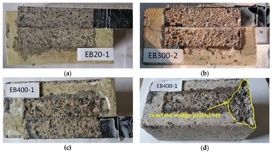
Figure 3.
Typical failure patterners of EB specimens for the following: (a) CFRP debonding (EB-TAC1), (b) CFRP debonding (EB-T3C2), (c) CFRP debonding (EB-T4C1), and (d) Failure surface (EB-T4C1).
3.1.2. HB Specimens
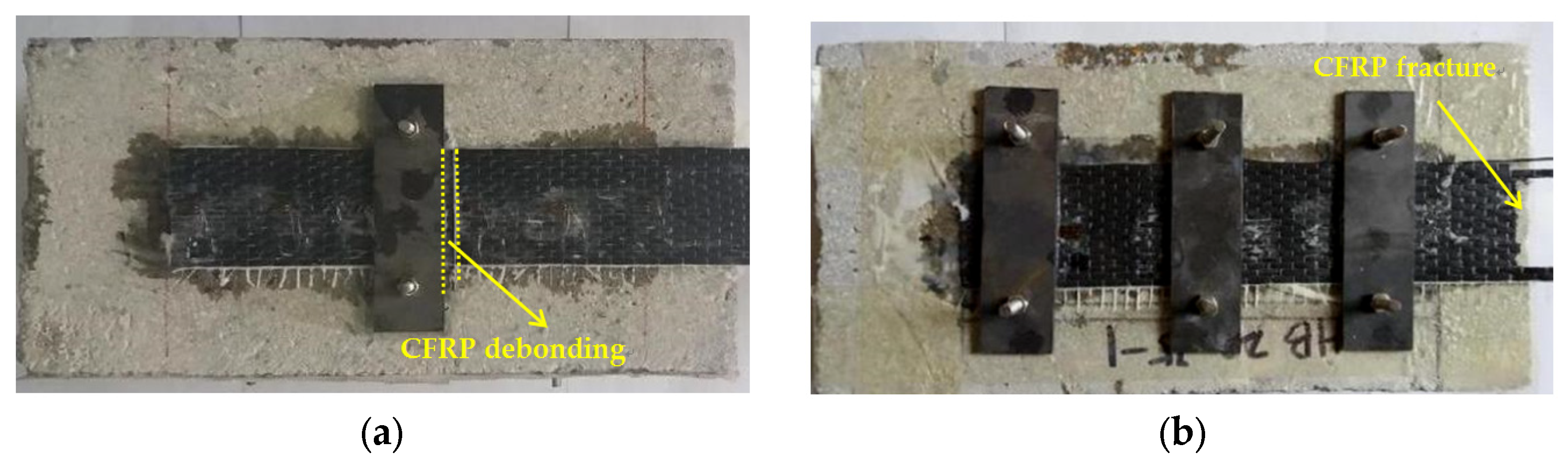
The failure patterns of the HB-CFRP joints observed in this experiment were classified into four types (as illustrated in Figure 4): CFRP debonding, CFRP fracture, CFRP debonding combined with bolt fracture, and CFRP debonding combined with the shear-tension failure of the concrete.
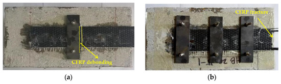
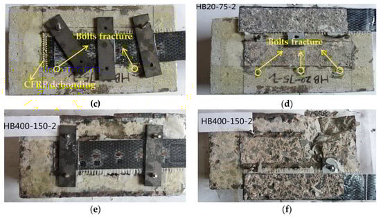
Figure 4.
Typical failure patterns of HB-CFRP specimens for the following: (a) CFRP debonding (HB-TAN1C1), (b) CFRP fracture (HB-TAN3C1), (c) CFRP debonding with bolts fracture (HB-TAN3C2), (d) Failure surface (HB-TAN3C2), (e) CFRP debonding with shear-tension failure of concrete (HB-T4N2C2), and (f) Failure surface (HB-T4N2C2).
Based on the test results, the failure pattern of the HB-CFRP joints was significantly influenced by the exposed temperature, the number of mechanical fasteners, and the CFRP layers. After exposure to high temperatures, the failure pattern of the single-layer HB-CFRP joints changed from CFRP debonding or CFRP fracture to CFRP debonding combined with bolt fracture. This may be attributed to the occurrence of concrete cracks after exposure to high temperatures, resulting in the increased roughness of concrete surfaces to increase the friction of the bond surfaces. As a result, the shear capacity of the bolt dominated the failure of the HB-CFRP joints with heat-damaged concrete.
With the increase in the numbers of mechanical fasteners, the failure patterns of the single-layer HB-CFRP joints with unheated concrete changed from CFRP debonding to fracture due to the increase in normal pressure on the bonded CFRP, which resulted in an increase in friction at debonding.
Most of the two-layer HB-CFRP joints failed due to CFRP debonding combined with bolt fracture because of the high ultimate strength of the two CFRP layers. As a result, the bond strength of the CFRP sheet to the adhesive layers and the shear capacity of the bolt dominated the failure of the HB-CFRP joint. As indicated in Figure 4e,f, the failure pattern of specimen HB-T4N2C2 was CFRP debonding combined with the shear-tension failure of concrete which leads to the mechanical fastener near the loaded end partially pulling out from the concrete substrate. This is mainly due to the decrease in the shear strength of concrete after exposure to high temperatures.
3.2. CFRP Strain Distribution
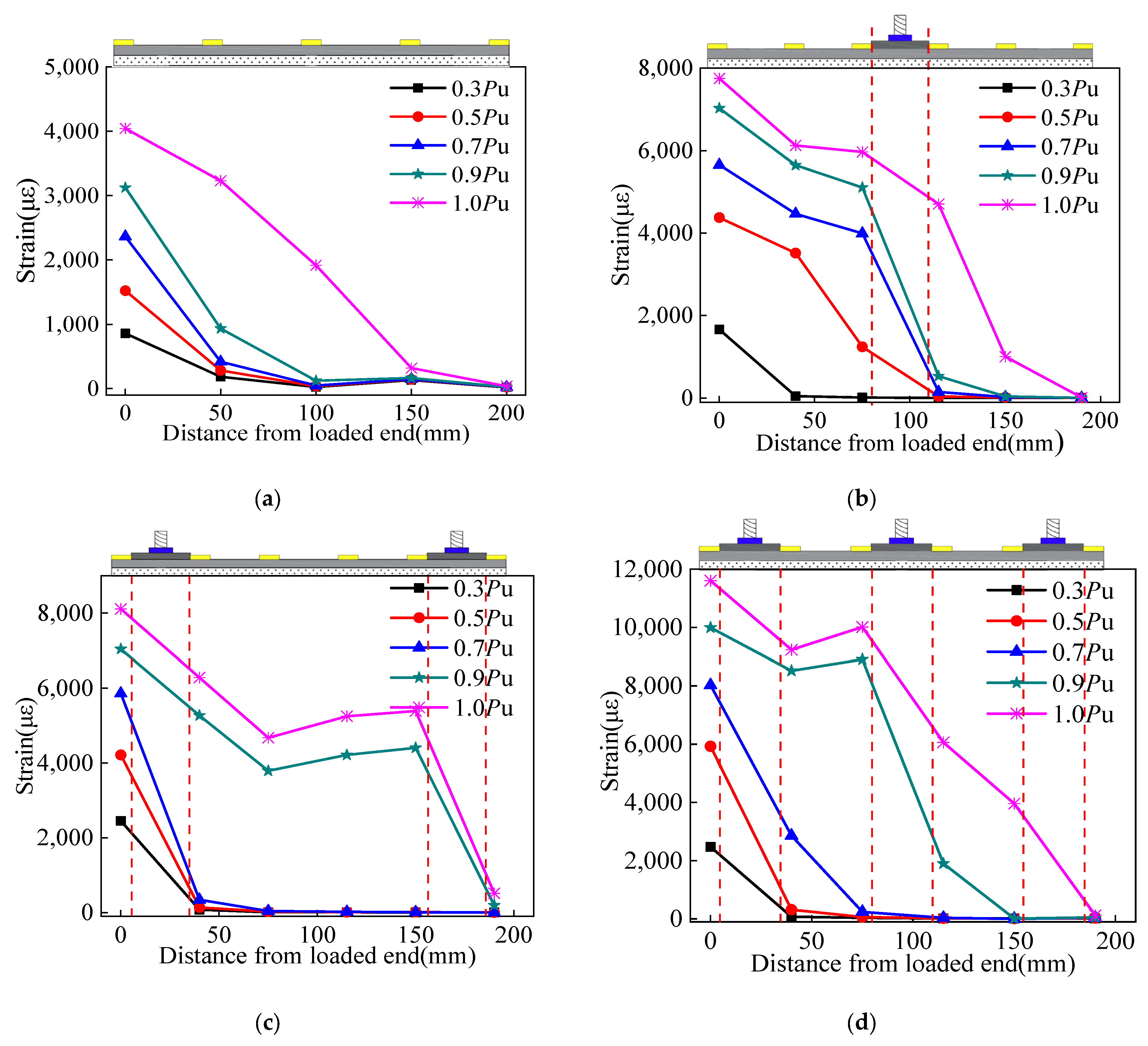
The distributions of CFRP strain along the bonded length at load levels of 30%, 50%, 70%, 90%, and 100% of the failure are illustrated in Figure 5.
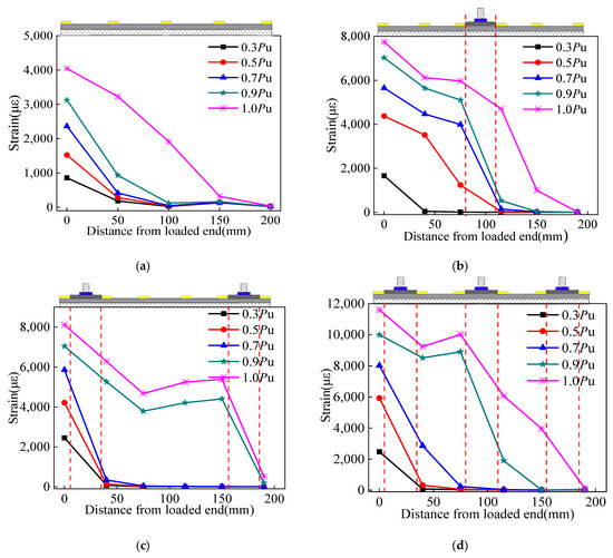
Figure 5.
Strain distributions in CFRP for the following: (a) EB-T4C2, (b) HB-TAN1C1, (c) HB-T1N2C1, and (d) HB-TAN3C1.
As illustrated in Figure 5a, for EB joints, the CFRP strain was mainly concentrated within 50 mm of the loading end when the load was less than 0.9 Pu, resulting in a steep slope. When the load increased to Pu, the strain near the loading end increased sharply and the strain developed toward to the free load, indicating the occurring of the debonding of the CFRP sheet.
For the one-fastener joint (see Figure 5b), the CFRP strain mainly concentrated in the area between the fastener and the loaded end, and significantly increased with an increase in the loading levels. Obviously, there was a low gradient of the CFRP strain between the fastener and the loaded end when the load was higher than 0.7 Pu, indicating the occurring of the debonding of the CFRP sheet before the fastener. In contrast, the CFRP strain was constantly low in the area between the fastener and the free end when the load was less than 0.9 Pu. Hence, there was a large gradient of the CFRP strain before and after the fastener, indicating the fastener delayed the propagating debonding cracks. When the load increased to Pu, the CFRP strain in the rear region of the fastener increased obviously, indicating the complete debonding of the CFRP.
For the two-fasteners joints (see Figure 5c), there was a large strain gradient at the fastener closest to the loaded end at low loading levels. When the loads increased to 0.9 Pu, the CFRP strain between the two fasteners began to obviously increase and showed a gentle gradient, indicating the strain passed through the fastener closest to the loaded end to the free end. The joints anchored with three fasteners showed similar strain development trends, which passed through, in turn, the fastener closest to the loaded end, the middle fastener, and the fastener closet to the free end with the increase in loading levels (see Figure 5d).
The strain distribution described above demonstrates that the mechanical fasteners could effectively hinder the debonding of the CFRP sheet, and contributed to the increase in the CFRP utilization rate, as illustrated in Table 1. For example, the utilization rate of single-layer CFRP joints with unheated concrete increased by 57.9%, 139.5%, and 136.8% when the number of mechanical fasteners increased to one, two, and three.
3.3. Ultimate Load
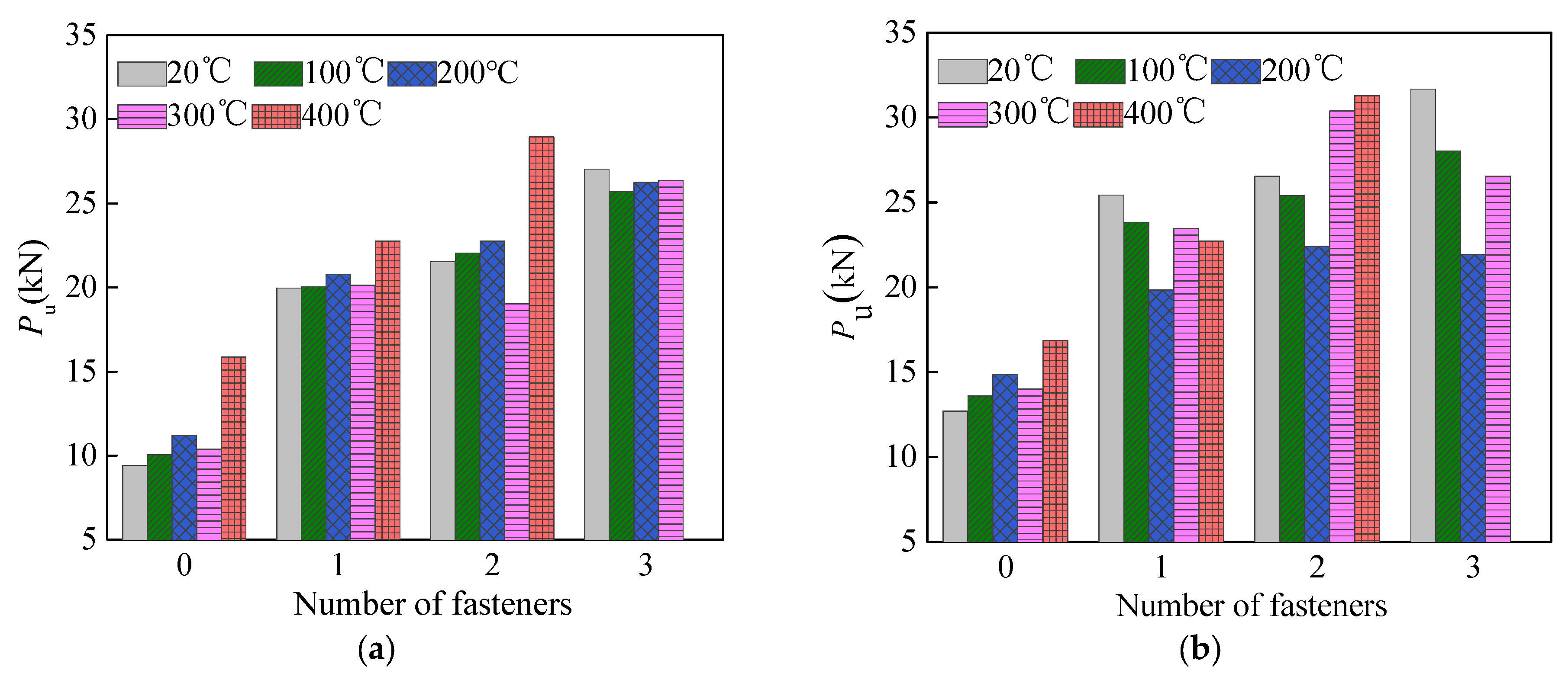
The ultimate load for the EB and HB joints is denoted as Pu and the values are listed in Table 1, as well as graphically illustrated in Figure 6.
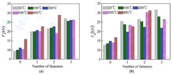
Figure 6.
Ultimate load of test specimens for the follwowing: (a) Single-layer CFRP and (b) Two-layers CFRP.
It shows that the ultimate load Pu of the joints increased with the number of the mechanical fasteners. Compared with single-layer EB-CFRP with unheated concrete (EB-TAC1), the ultimate load increased by 111.77%, 128.42%, and 186.74% for the HB-CFRP joints, respectively, anchored with one, two, and three mechanical fasteners. While the HB-CFRP joints with heat-damaged concrete showed lower increases in ultimate load with the increase in the numbers of the mechanical fastener. This is largely since the exposure to high temperature causes damage to the concrete, making the bond between the heat-damaged concrete and the fasteners worse.
The ultimate loads of the joints affected by exposure to high temperatures are summarized as follows. The EB-CFRP joints provide the ultimate load with a slight increase below the temperature of 200 °C, a slight decrease at the temperature of 300 °C, followed by a significant increase at a temperature of 400 °C. The single-layer HB-CFRP joints anchored with one or two fasteners present a similar trend (Figure 6a). This is probably due to two reasons. On the one hand, high temperatures over 100 °C cause pores and cracks in the concrete, through which the epoxy penetrates into the heat-damaged concrete, which results in an improvement in the bond performance of the CFRP to heated concrete. On the other hand, the compressive of the concrete decreases obviously after exposure to high temperatures over 300 °C, which results in the deterioration of their bond behavior. In the end, the ultimate loads of the joints neither monotonically decrease nor increase with the increase in the exposure temperature. Moreover, the ultimate loads of the single-layer EB- and HB-CFRP joints anchored with one or two fasteners with heat-damaged concrete were mostly higher than those of the joints with unheated concrete, while the ultimate loads of the HB-CFRP joints anchored with three fasteners decreased after exposure to high temperatures. This can be explained by the result that the high temperature leads to a decrease in concrete strength, making substrate concrete vulnerable to damage during the hole-drilling process.
4. Bond Strength Analytical Model
4.1. Strength Analytical Model
Based on the test results, the analytical model needs to predict three distinct possible failure mechanisms for HB-CFRP joints with heat-damaged concrete.
4.1.1. CFRP Bonding
Based on the mechanism proposed by Wu et al. [30], the load corresponding to FRP bonding consists of three parts: the interfacial adhesion (Pa) of FRP, the friction bond strength (Pf), and the dowel force of the anchor (Pd). However, the dowel force of the anchor Pd is very small, and generally not considered. Therefore, the FRP bonding load can be calculated as follows:
The friction force Pf comes from the normal pressure that is exerted on the FRP sheet by the mechanical fasteners, as shown in Equation (2).
where m is the total number of mechanical fasteners; μ is the friction coefficient between two rough concrete surfaces; and Na is the normal pressure exerted on the FRP strip by one mechanical fastener.
Although the friction coefficient between two rough concrete surfaces after high temperatures was a little higher than that at ambient temperature due to the heated cracks, it is still taken as 0.96, as measured by Wu et al., at ambient temperature [30].
Na can be calculated using Equation (3).
where T is the applied torque (N·m); D is the diameter of the screw bolt (mm); and k is the torque coefficient, which was determined to be 0.245 using the test.
The interfacial adhesion Pa has been well studied by many researchers under ambient temperatures. Among them, the model proposed by Chen and Teng [40], based on fracture mechanics, was proven to be valid by comparing the calculated bond strength with the measured values of a series of specimens tested by the authors and other researchers. However, the temperature of heat-damaged concrete was not considered in this model.
Liu et al. modified the model (Chen–Teng) to make it applicable to the bond strength of EB-CFRP joints with heat-damaged concrete, based on experimental data tested by the authors and other researchers [21]. The modified model to predict the bond strength of EB-FRP with heat-damaged concrete is as follows:
where is a regression coefficient; is a bond width factor; is a bond length factor; and is the cylinder compressive strength of concrete at elevated temperatures.
equals to 1 at ambient temperature, while it was determined by fitting the experimental results of the EB-CFRP joints with heat-damaged concrete, as given in Equation (5).
where T is the exposure temperature of the concrete.
where and are the width of CFRP sheets and concrete block, respectively.
where L is the CFRP bond length (mm); is the effective bond length; and Ep and tp are the modulus of elasticity and the thickness of FRP.
is given in Equation (9) [41].
where is the cylinder compressive strength of the concrete under an ambient temperature (MPa).
4.1.2. CFRP Bonding Combined with Bolt Fracture
As observed in this test, the bolt fracture was followed by CFRP bonding for some HB-CFRP joints. The fracture of the bolts leads to the release of the normal pressure exerted on the CFRP sheet, resulting in the loss of friction on the interface between the HB-CFRP and the concrete. As a result, the ultimate load corresponding to this combined failure consists of two parts: the interfacial adhesion (Pa) of the CFRP and the shear strength of the bolts, as shown in Equation (10):
where Pa is the interfacial adhesion that was calculated using Equation (4) and Ps is the shear strength of the bolt that was calculated using Equation (11):
in which is the allowable shear strength of the bolt (MPa) and Am is the cross-sectional area of a single bolt (mm2).
Bolt fracture failure is an undesirable failure when it comes to structural retrofitting, as this would mean that the mechanical fastener is insufficient. Taking this into consideration, treating the bolt fracture as a failure pattern should be avoided for design purposes, with a minimum cross-sectional area of a single bolt being sufficient to ensure the shear capacity of the bolts.
4.1.3. Fracture of CFRP
Based on the assumption of a linear relationship between the stress and strain of CFRP, the load corresponding to the fracture of the CFRP sheet can be given as follows:
where n is the number of CFRP layers; AFRP is the cross-sectional area of a single CFRP layer; and fFRP is the ultimate tensile strength of the CFRP.
For design purposes, the ultimate strength of the HB-CFRP with unheated and heat-damaged concrete is given using Equation (13).
4.2. Calibration of the Proposed Model
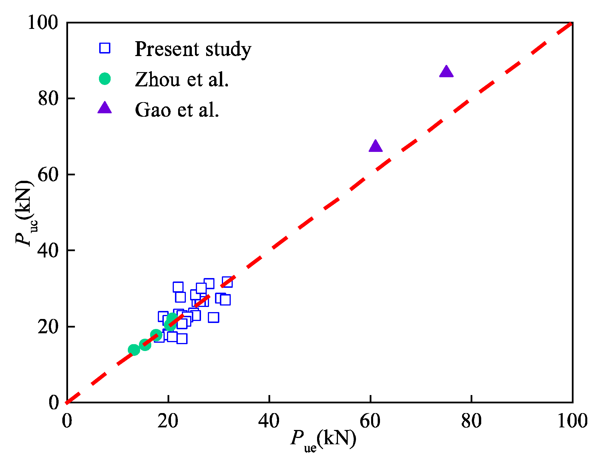
The calculated and experimental ultimate strength are denoted as Puc and Pue, illustrated in Figure 7, which shows that the modified ultimate load model of the HB-FRP joints with unheated and heat-damaged concrete has good accuracy. The average ratio of the calculated to experimental values for the HB-FRP joints is 0.991, with a variation coefficient of 0.038.

Figure 7.
Comparison of calculated with experimental ultimate strength [33,36].
5. Conclusions
In this paper, an experimental and analytical investigation was carried out to study the bond performance of the HB-CFRP joints with heat-damaged concrete. Based on the results, the following conclusions can be drawn:
- (1)
- The exposed temperature and number of mechanical fasteners have an obvious effect on the failure mode of the HB-CFRP joints. After exposure to 400 °C, the HB-CFRP joints were prone to fail due to the shear-tension failure of the concrete that lost the shear strength. The increase in the number of mechanical fasteners changed the failure patterns of the single-layer HB-CFRP joints with unheated concrete from the debonding to the fracture of the CFRP, due to the increase in normal pressure on the bonded CFRP.
- (2)
- In comparison with the reference joints without fasteners, the utilization rate of single-layer CFRP joints with unheated concrete increased by 57.9%, 139.5%, and 136.8% when the number of mechanical fasteners increased to one, two, and three. Accordingly, the ultimate strength increased by 111.77%, 128.42%, and 186.74%.
- (3)
- The ultimate load of most EB- and HB-CFRP joints anchored with no more than three fasteners is higher than that of the reference joints when the exposed temperature is no more than 400 °C. However, the ultimate load of the HB-CFRP joints anchored with three fasteners decreases after exposure to high temperatures due to the loss of strength of heat-damaged concrete.
- (4)
- A predictive model for the bond strength of the HB-FRP joints with unheated and heat-damaged concrete interface was proposed. Its validity was verified by comparing the calculated with the measured bond strengths of a series of specimens tested by the authors and other researchers.
Author Contributions
Methodology, G.L. and F.Q.; investigation and writing—original draft, Y.W., X.G., Y.L. and S.C.; writing—review, G.L. and F.Q.; funding acquisition, F.Q. and G.L. All authors have read and agreed to the published version of the manuscript.
Funding
This research was funded by the CSCEC Technology Research and Development Project, China (grant number CSCEC-2021-Z-24) and the Key Scientific Research Projects of Universities in Henan Province, China (grant number 23A570007).
Institutional Review Board Statement
Not applicable.
Informed Consent Statement
Not applicable.
Data Availability Statement
The data presented in this study are available on request from the corresponding author.
Conflicts of Interest
Author Y.W. and S.C. were employed by China Construction Seventh Engineering Bureau Co., Ltd. The remaining authors declare that the research was conducted in the absence of any commercial or financial relationships that could be construed as a potential conflict of interest.
References
- Thongchom, C.; Lenwari, A.; Aboutaha, R.S. Effect of sustained service loading on post-fire flexural response of reinforced concrete T-beams. ACI Struct. J. 2019, 116, 243–254. [Google Scholar] [CrossRef]
- Yu, Y.; Hang, Z.; Zhao, W.; Zhao, X. Fire-resistance mechanism and residual bearing capacity of prestressed concrete beams after fire exposure. J. Struct. Eng. 2021, 147, 4021109. [Google Scholar] [CrossRef]
- Xu, Y.Y.; Chen, Y.X.; Yan, B.; Zhen, R.L.; Luo, Y. Post-fire seismic behaviors of concrete stub columns in different fire exposure cases. J. Vib. Shock. 2020, 39, 11–19. (In Chinese) [Google Scholar]
- Demir, U.; Unal, G.; Goksu, C.; Goksu, C.; Saribas, I.; Ilki, A. Post-fire seismic behavior of RC columns built with sustainable concrete. J. Earthq. Eng. 2022, 26, 6869–6892. [Google Scholar] [CrossRef]
- Liu, G.R.; Song, Y.P.; Qu, F.L. Post-fire cyclic behavior of reinforced concrete shear walls. J. Cent. South. Univ. T. 2010, 17, 1103–1108. [Google Scholar] [CrossRef]
- Timilsina, S.; Yazdani, N.; Beneberu, E. Post-fire analysis and numerical modeling of a fire-damaged concrete bridge. Eng. Struct. 2021, 244, 112764. [Google Scholar] [CrossRef]
- Liu, X.; Yu, C.; Quan, W.; Chen, L. Inspection, materials testing and field testing of a prestressed concrete box bridge after fire exposure. Fire. Safety. J. 2019, 108, 102852. [Google Scholar] [CrossRef]
- Zaman, A.; Gutub, S.A.; Wafa, M.A. A review on FRP composites applications and durability concerns in the construction sector. J. Reinf. Plast. Comp. 2013, 32, 1966–1988. [Google Scholar] [CrossRef]
- Mugahed Amran, Y.H.; Alyousef, R.; Rashid, R.S.M.; Alabduljabbar, H.; Hung, C.C. Properties and applications of FRP in strengthening RC structures: A review. Structures 2018, 16, 208–238. [Google Scholar] [CrossRef]
- Naser, M.Z.; Hawileh, R.A.; Abdalla, J.A. Fiber-reinforced polymer composites in strengthening reinforced concrete structures: A critical review. Eng. Struct. 2019, 198, 109542. [Google Scholar] [CrossRef]
- Wu, J.Y.; Zhu, Y.Q.; Li, C.G. Experimental investigation of fatigue capacity of bending-anchored CFRP cables. Polymers 2023, 15, 2483. [Google Scholar] [CrossRef]
- Xian, G.J.; Guo, R.; Li, C.G. Combined effects of sustained bending loading, water immersion and fiber hybrid mode on the mechanical properties of carbon/glass fiber reinforced polymer composite. Comp. Struct. 2022, 281, 115060. [Google Scholar] [CrossRef]
- Al-Nimry, H.S.; Haddad, R.H.; Afram, S.K.; Abdel-Halim, M.A. Effectiveness of advanced composites in repairing heat-damaged RC columns. Mater. Struct. 2013, 46, 1843–1860. [Google Scholar] [CrossRef]
- Al-Kamaki, Y.S.S.; Al-Mahaidi, R.; Bennetts, I. Experimental and numerical study of the behaviour of heat-damaged RC circular columns confined with CFRP fabric. Compos. Struct. 2015, 133, 679–690. [Google Scholar] [CrossRef]
- Kumar, H.; Maheswaran, C.; Agarwal, A.; Shanmugam, S.P. Effectiveness of hybrid fibre-reinforced polymer retrofitting on behaviour of fire damaged RC columns under axial compression. Eng. Struct. 2020, 211, 110458. [Google Scholar]
- Yu, J.T.; Yuan, L.; Lu, Z.D.; Kai, X. Flexural performance of fire damaged and rehabilitated two span reinforced concrete slabs and beams. Struct. Eng. Mech. 2012, 42, 799–813. [Google Scholar] [CrossRef]
- Xu, Q.; Chen, L.; Han, C.; Harries, K.A.; Xu, Z. Experimental research on fire-damaged RC continuous T-beams subsequently strengthened with CFRP sheets. Eng. Struct. 2019, 183, 135–149. [Google Scholar] [CrossRef]
- Abdulrahman, A.S.; Kadir, M.R.A. Behavior and flexural strength of fire-damaged high-strength reinforced rectangular concrete beams with tension or compression zones exposed to fire repaired with CFRP sheets. Case. Stud. Constr. Mat. 2021, 15, e00779. [Google Scholar] [CrossRef]
- Haddad, R.H.; Al-Rousan, R.; Almasry, A. Bond-slip behavior between carbon fiber reinforced polymer sheets and heat-damaged concrete. Compos. Part B-Eng. 2013, 45B, 1049–1060. [Google Scholar] [CrossRef]
- Xu, Y.; Lin, Y.; Dong, Y.; Zhang, D.; Shen, X. Experimental study on interface bond performance between CFRP and concrete after elevated temperature. J. Build. Struct. 2015, 36, 133–141. (In Chinese) [Google Scholar]
- Liu, G.R.; Qu, F.L.; Zhao, S.B.; Zhang, H.Y. Bond-slip behavior between CFRP sheets and heat-damaged concrete. J. Build. Struct. 2019, 40, 156–162. (In Chinese) [Google Scholar]
- Smith, S.; Teng, J. FRP-strengthened RC beams. I: Review of debonding strength models. Eng. Struct. 2002, 24, 385–395. [Google Scholar] [CrossRef]
- Teng, J.; Smith, S.; Yao, J.; Chen, J. Intermediate crack-induced debonding in RC beams and slabs. Constr. Build. Mater. 2003, 17, 447–462. [Google Scholar] [CrossRef]
- Fu, B.; Chen, G.; Teng, J. Mitigation of intermediate crack debonding in FRP-plated RC beams using FRP U-jackets. Compos. Struct. 2017, 176, 883–897. [Google Scholar] [CrossRef]
- Zhang, P.; Lei, D.; Ren, Q.; He, J.; Yang, Z. Experimental and numerical investigation of debonding process of the FRP plate-concrete interface. Constr. Build. Mater. 2019, 235, 117457. [Google Scholar] [CrossRef]
- Lamanna, A.J.; Bank, L.C.; Scott, D.W. Flexural strengthening of reinforced concrete beams using fasteners and fiber-reinforced polymer strips. ACI Struct. J. 2001, 98, 368–376. [Google Scholar]
- Bank, L.C.; Arora, D. Analysis of RC beams strengthened with mechanically fastened FRP (MF-FRP) strips. Compos. Struc. 2007, 79, 180–191. [Google Scholar] [CrossRef]
- Elsayed, W.E.; Ebead, U.A.; Neale, K.W. Studies on mechanically fastened fiber-reinforced polymer strengthening systems. ACI Struct. J. 2009, 106, 49–59. [Google Scholar]
- Wu, Y.F.; Huang, Y. Hybrid bonding of FRP to reinforced concrete structures. J. Compos. Constr. 2008, 12, 266–273. [Google Scholar] [CrossRef]
- Wu, Y.F.; Van, J.H.; Zhou, Y.W.; Xiao, V. Ultimate strength of reinforced concrete beams retrofitted with hybrid bonded fiber-reinforced polymer. ACI Struct. J. 2010, 107, 451–460. [Google Scholar]
- Wu, Y.F.; Wang, Z.; Kang, L.; Wei, H. Numerical analyses of hybrid-bonded FRP strengthened concrete beams. Comput-aided. Civ. Inf. 2010, 24, 371–384. [Google Scholar] [CrossRef]
- Guan, Y.H.; Jiang, B.S.; Song, X.G. Experimental study and numerical simulation on bonding behavior of the new HB-FRP strengthening technology. J. Perform. Constr. Fac. 2012, 26, 220–227. [Google Scholar] [CrossRef]
- Zhou, Y.W.; Wang, X.; Sui, L.; Xing, F.; Huang, Z.; Chen, C.; Li, P.; Mei, L. Effect of mechanical fastening pressure on the bond behaviors of hybrid-bonded FRP to concrete interface. Compos. Struct. 2018, 204, 731–744. [Google Scholar] [CrossRef]
- Wu, Y.F.; Liu, K. Characterization of mechanically enhanced FRP bonding system. J. Compos. Constr. 2013, 17, 34–49. [Google Scholar] [CrossRef]
- Chen, C.; Sui, L.; Xing, F.; Li, D.; Zhou, Y.; Li, P. Predicting bond behavior of HB FRP strengthened concrete structures subjected to different confining effects. Compos. Struct. 2018, 187, 212–225. [Google Scholar] [CrossRef]
- Gao, L.; Zhang, F.; Liu, J.; Lu, X.; Gao, H. Experimental and numerical study on the interfacial bonding characteristics of FRP-to-concrete joints with mechanical fastening. Constr. Build. Mater. 2018, 199, 456–470. [Google Scholar] [CrossRef]
- Xue, C.C.; Yu, M.; Xu, H.M.; Xu, L.H.; Saafi, M.; Ye, J.Q. Compressive performance and deterioration mechanism of ultra-high performance concrete with coarse aggregates under and after heating. J. Build. Eng. 2023, 64, 105502. [Google Scholar] [CrossRef]
- Kim, W.; Choi, H.; Lee, T. Residual compressive strength prediction model for concrete subject to high temperatures using ultrasonic pulse velocity. Materials. 2023, 16, 515. [Google Scholar] [CrossRef]
- Wu, Z.M.; Hu, C.H.; Wu, Y.F.; Zheng, J.J. Application of improved hybrid bonded FRP technique to FRP debonding prevention. Constr. Build. Mater. 2011, 25, 2898–2905. [Google Scholar] [CrossRef]
- Chen, J.F.; Teng, J.G. Anchorage strength models for FRP and steel plates bonded to concrete. J. Struct. Eng. 2001, 127, 784–791. [Google Scholar] [CrossRef]
- Chang, Y.F.; Chen, Y.H.; Sheu, M.S.; Yao, G.C. Residual stress-strain relationship for concrete after exposure to high temperatures. Cement. Concrete. Res. 2006, 36, 1999–2005. [Google Scholar] [CrossRef]


Disclaimer/Publisher’s Note: The statements, opinions and data contained in all publications are solely those of the individual author(s) and contributor(s) and not of MDPI and/or the editor(s). MDPI and/or the editor(s) disclaim responsibility for any injury to people or property resulting from any ideas, methods, instructions or products referred to in the content. |
© 2023 by the authors. Licensee MDPI, Basel, Switzerland. This article is an open access article distributed under the terms and conditions of the Creative Commons Attribution (CC BY) license (https://creativecommons.org/licenses/by/4.0/).