Article

Numerical Simulation Study of Basement Water Discharge Pressure Relief Method under Rainstorm Conditions

1
School of Resources and Safety Engineering, Central South University, Changsha 410083, China
2
Hunan Huda Civil Engineering Testing Co., Ltd., Changsha 410083, China
*
Author to whom correspondence should be addressed.
Buildings 2023, 13(11), 2772; https://doi.org/10.3390/buildings13112772
Submission received: 24 September 2023 / Revised: 27 October 2023 / Accepted: 30 October 2023 / Published: 3 November 2023
(This article belongs to the Section Building Structures)

Abstract

:
The development and expansion of underground space has led to a continuous increase in both the occupied area and the burial depth of underground basements. Meanwhile, due to the inaccurate estimation of groundwater buoyancy, more and more anti-floating problems of underground basement caused by rainstorm have emerged. Combined with the principles of unsaturated seepage theory, this article uses Flac3d 6.0 software to conduct simulations on the influence of various significant factors on the effect of the water discharge pressure relief method, a novel approach to reduce buoyancy. The numerical results show that the water discharge pressure relief method can ensure the stability of the basement under rainstorm conditions compared with the basement without drainage holes. In order to improve the anti-floating efficiency of the water discharge pressure relief method in preventing floating, it is recommended to initially decrease the height and spacing of the drainage holes and follow by increasing the aperture of the drainage holes. The recommended spacing of the drainage holes is between 2 m and 3 m. The height of the drainage holes should be between 1 m and 1.5 m, and the aperture of the drainage holes should be no smaller than 100 mm. Furthermore, the water head of the basement floor is proportional to the permeability of the lower backfill and cushion, and it is not significantly influenced by the upper backfill soil when its permeability is within a low range. Finally, in order to achieve a satisfactory anti-floating effect, it can be attempted to reduce the longitudinal width of the lower backfill soil or moderately increase the thickness of the cushion.

1. Introduction

The expansion of underground space in urban areas has led to an increase in both the floor area and the buried depth of underground basements. At the same time, the issue of basement anti-floating problems caused by rainstorms has become increasingly prevalent in recent years [1,2,3,4,5,6]. For instance, the basement of China Travel Service Hotel in Baoan District, Shenzhen experienced significant uplift of the floor, reaching a maximum of 160 mm, as a result of continuous rainstorms that occurred after its completion [2]. Similarly, in a southern Jiangxi underground garage, continuous rainstorms caused rainwater to flow into the foundation pit, resulting in a maximum uplift of the floor reaching 292 mm [3]. Furthermore, in 2021, heavy rainstorms in Zhengzhou caused the loss of backfill soil around a two-level basement, leading to shearing and damage of the basement floor, with a maximum uplift of 270 mm [4]. Hence, it is evident that conducting research on the prevention of basement floating under rainstorms holds significant practical importance in terms of ensuring basement safety and minimizing economic losses [7,8,9,10].
At present, the anti-floating design methods of basements mainly include “passive” [11,12,13] and “active” [14,15,16,17,18,19,20,21] anti-floating methods. The “passive” anti-floating measures pertain to conventional anti-floating technologies, including the self-weight anti-floating method, the anti-floating anchor rod, and the anti-floating pile. These methods enhance the anti-floating force of underground structures by increasing their weight and installing anti-floating anchor rods and anti-floating piles. This approach ensures the stability of the basement by resisting the forces that cause floating. The utilization duration of “passive” anti-floating measures is longer, and the technology has reached a higher level of maturity [22,23,24]. However, the construction period is prolonged, and the associated costs are elevated. When there are frequent fluctuations in the groundwater level, the implementation of “passive” anti-floating measures becomes significantly challenging and lacks proper guidance [25].
Compared to the “passive” anti-floating measures, the “active” anti-floating measures such as the water discharge pressure relief method effectively reduce the groundwater level by strategically placing drainage holes on the side wall or floor of the basement. This approach ensures the structural integrity and safety of the basement. The water discharge anti-floating method, characterized by its simplicity, short construction period, and low cost, holds significant practical value for underground engineering construction. Zhang et al. [26] employed the water discharge pressure relief method to implement the anti-floating design for the two-level underground garage. Compared to the previous anti-floating anchor scheme, a cost reduction of CNY 11.94 million was achieved, and the construction period was shortened by approximately 2 months. Consequently, it is evident that the water discharge anti-floating method yields significant economic advantages.
For the water discharge and pressure relief method, Xu et al. [27] conducted numerical simulation research on the swimming pool using the two-dimensional seepage finite element program SEEP/W. The findings indicate that increasing the thickness of the cushion at the pool’s bottom and incorporating a large number of drainage holes with a small diameter are helpful to achieve good anti-floating effect. Gan et al. [28] conducted a comparative study to investigate the influence of drainage hole spacing and the consolidation degree of surface backfill soil on the discharge effect. Yang et al. [29] employed an orthogonal test to analyze the influence of backfill consolidation, backfill width, spacing of drainage hole, and basement floor disturbance on the anti-floating effect. However, some scholars ignored the significance of rainfall infiltration in relation to groundwater levels. They neglected to investigate the patterns and principles governing the water discharge pressure relief method under rainstorm conditions. Furthermore, it is of utmost importance to guarantee the safety of the basement during adverse weather conditions, such as heavy rainstorms, in the field of practical engineering. Accordingly, this article uses Flac3d 6.0 numerical simulation software [30,31,32,33] to simulate and analyze the various influencing factors of the water discharge anti-floating method individually, specifically under rainstorm conditions. And on this basis, this article observes the influence of a single factor on the anti-floating effect and provides an analysis of the seepage and stability of the basement under specific working conditions.

2. Materials and Methods

2.1. Water Discharge Pressure Relief Method

The water discharge pressure relief method, as proposed by Yuan [34], is specifically designed for basements located in low-permeability soil layers. The underlying working principle of this method is illustrated in Figure 1. The groundwater level exhibits a rapid increase during rainstorm conditions. When the groundwater level exceeds the elevation of the drainage hole located on the side wall of the basement, the pore water within the soil layer surrounding the basement is directed into the indoor drainage system via the drainage hole. And the anti-filter layer wrapped by a geotextile outside the drainage hole can filter sediment and particles. It is efficient to reduce the amount of water flowing into the basement cushion so as to control the water buoyancy of the basement floor and ensure the safety and stability of the basement [35,36] under rainstorm conditions. When the water in the water-collecting well reaches a specific level, the pumping system is automatically activated to transfer the water into the urban pipe network system so as to achieve the purpose of anti-floating in the basement.
According to the schematic diagram of the water discharge pressure relief method shown in Figure 1, several key factors influence the effectiveness of preventing flotation. These factors include the parameters (such as height, spacing, and aperture) of the drainage holes located on the side wall, the permeability of the upper backfill soil, the longitudinal width and permeability of the lower backfill, as well as the thickness and permeability of the cushion. Thus, it is necessary for this article to conduct numerical simulation tests to examine the various influencing factors and analyze their impact on the effectiveness of the water discharge pressure relief method in preventing floating under rainstorm conditions. This analysis aims to establish a scientific foundation for the design of anti-floating measures in basements.

2.2. Unsaturated Seepage Theory

Rainfall infiltration is a seepage process that occurs in unsaturated conditions. The Van Genuchten (VG) model, as proposed by Van Genuchten [37], is widely applicable in the field of unsaturated seepage calculation, particularly for most soil types. The expression is as follows:
S e = S r + 1 S r 1 + p a n m ,
k r S e = S e 1 2 1 1 S e 1 m m 2 ,
k = k r · k s .
In the expression, Se (−) is the volume moisture content; Sr (−) is the residual volume moisture content; p (kPa) is negative pore water pressure; a, m, n (−) are the fitting parameters, where m = 1 − 1/n and n = 2, for soil, a = 100; k (cm/s) is the permeability coefficient; ks (cm/s) is the saturating permeability coefficient; kr (−) is the relative permeability coefficient.
According to the relationship between saturation, negative pore water pressure and permeability coefficient of the soil in the VG model, the unsaturated seepage module is achieved in Flac3d by the Fish language. The calculation of the unsaturated permeability coefficient involves determining the negative pore water pressure value of the unit. And the permeability coefficient of the unit is corrected in every calculation step with the help of the cyclic function so as to achieve the unsaturated seepage calculation for the water discharge pressure relief method. The calculation of permeability for the unsaturated unit in Flac3d is shown in Figure 2.

2.3. Project Overview and Numerical Simulation Calculation Model

This article uses the three-dimensional finite element software Flac3d 6.0 to carry out the numerical simulation by taking a 1-level basement as the project example. The qualitative study examines the relationship between the influencing factors and the anti-floating effect under rainstorm conditions.
According to the Code for Design of Building Foundation (GB50007-2011) [38], the anti-floating stability of a basement is determined by the ratio of its self-weight to water buoyancy. The self-weight of the basement includes the weight of the basement structure and the upper covering soil. In the design of the basement, it is imperative to ensure safety by maintaining a ratio of the self-weight of the basement to the buoyancy of water that is not less than 1.05. In the Fluid Mechanics, the concept of water buoyancy can be quantified using the term “water head.” The expression of the aforementioned statement is as follows:
p = ρ · g · h .
In the expression, p (kPa) is the water buoyancy; ρ (kg/m3) is the water density; g (N/kg) is the gravitational acceleration; h (m) is the water head. Therefore, the primary criterion for evaluating the anti-floating effect could be the maximum water head of the basement floor.
The elevation of the basement surface is 62.50 m above sea level (m a.s.l.). The elevation of the basement floor is 56.50 m above sea level (m a.s.l.). The sidewall thickness of the structure is 30 cm, while the floor thickness measures 50 cm. At present, the elevation of the stable water table is approximately 56.50 m above sea level (m a.s.l.). However, the site is subject to the influence of climate and environmental factors, resulting in significant fluctuations in the groundwater level. According to the calculation, the theoretical anti-floating water head of the basement is determined to be 3.73 m. This indicates that the basement has the capacity to withstand water pressure of 36.52 kPa, taking into account the self-weight of the structure and the weight of the upper covering soil. And the size of the design anti-floating water head of the basement is 3.55 m, which means that we should control the maximum water pressure of basement floor below 34.75 kPa in the basement design for safety reasons. In practical engineering applications, the design of the anti-floating water head is commonly employed as the crucial water head for ensuring the safety of basements.
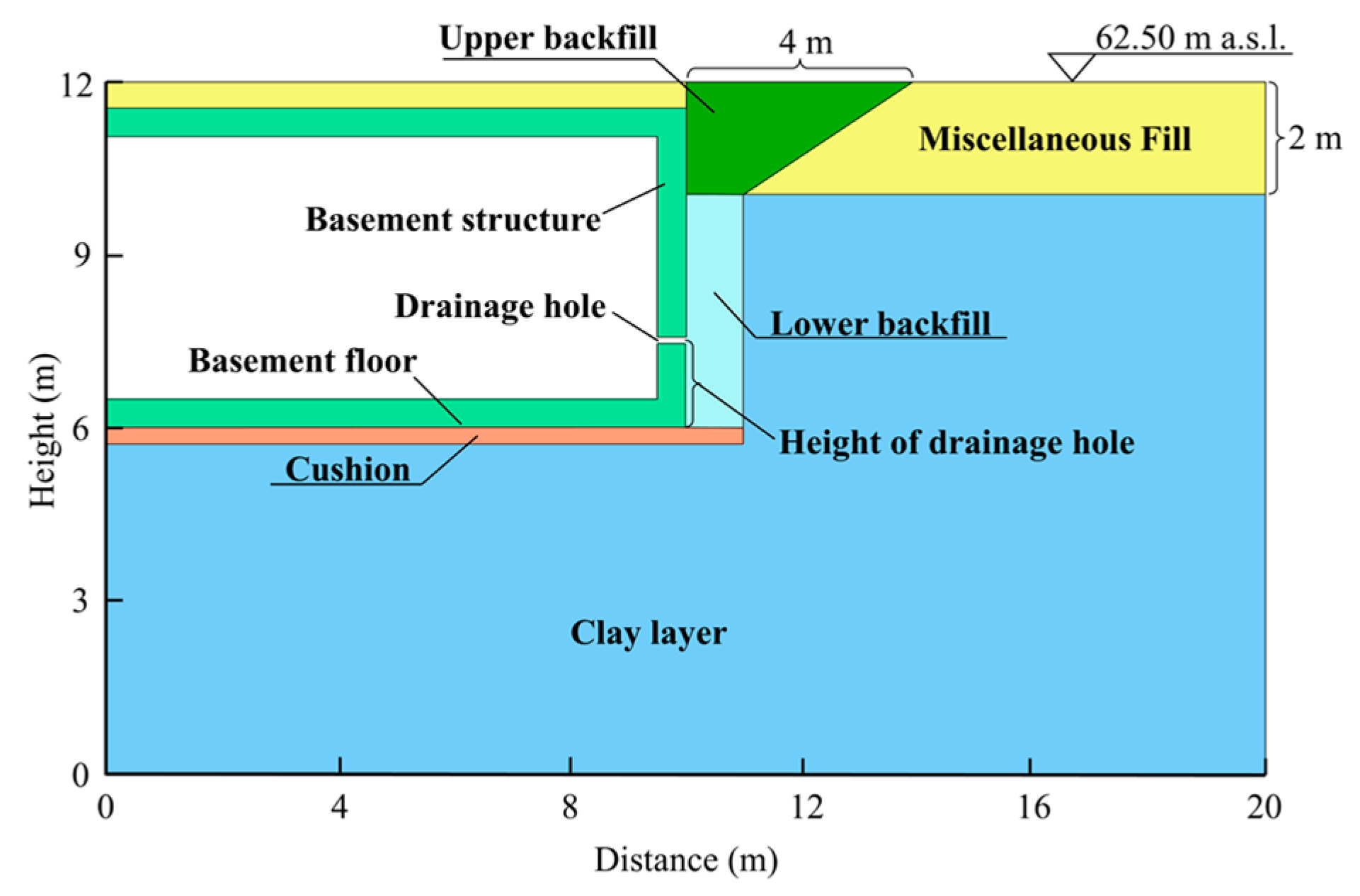
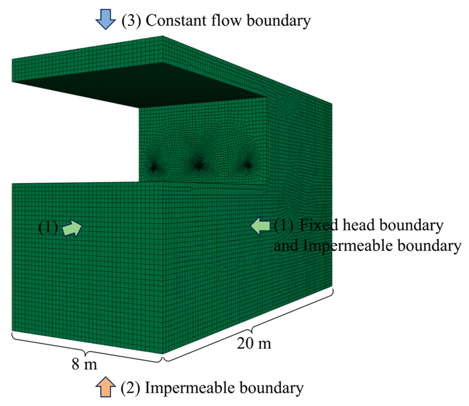
The southern side of the basement measures 180 m in length, making it the largest area for pressure relief. The diameter of the drainage hole ranges from 80 mm to 120 mm; however, the size difference between the two extremes is significant. The generated units exceed 20 million when the entire basement is modeled, posing a challenge in terms of calculation. Thus, the pressure relief surface is 8 m long in the calculation model. The longitudinal width of the basement measures 10 m, while the longitudinal width of the soil layer behind the pressure relief surface also measures 10 m. The local grid surrounding the drainage holes is densified to ensure accurate calculations. The cross-sectional view of the model is shown in Figure 3.
As shown in Figure 3, once the main structure of the basement is completed, the basement roof and foundation pit are covered and backfilled in the construction period. The soil covering the structure of the basement roof and the surface soil on the site is relatively loose and has high permeability. It is classified as miscellaneous fill with a thickness of 2 m. The backfill soil at the lower part of the foundation pit around the basement is compacted in layers during the backfilling process. The soil structure is denser, and the permeability is lower. The lower backfill thickness is 4 m and the longitudinal width is 1 m in this model. The backfill soil surrounding the basement in the upper section of the foundation pit achieves its highest density through repeated compaction treatments. The upper backfill exhibits the lowest permeability, with a thickness of 2 m. Additionally, a cushion layer with a thickness of 30 cm is placed beneath the basement floor. The basic parameters of each soil layer around the basement are shown in Table 1.

2.4. Rainfall Intensity and Boundary Conditions

According to the daily rainfall data of nearly 50 years near the basement and occasionality of maximum rainfall [39], this article simulates the extreme situation of a 48 h rainstorm in the basement, and the rainfall intensity is 100 mm/d. Considering the high density of buildings surrounding the basement, surface runoff diminishes the infiltration of rainfall into the soil. According to the Outdoor Drainage Design Standard (GB50014-2021) [40], the comprehensive runoff coefficient is 0.6, and as a result, the actual rainfall intensity is reduced accordingly. When the rainfall intensity is less than the maximum infiltration rate of the surface soil, the infiltration amount is determined by rainfall intensity. Conversely, when the rainfall intensity exceeds the maximum infiltration rate of the surface soil, the infiltration amount is determined by the maximum infiltration rate. Considering that the rainfall infiltration condition is actually a dynamic boundary condition [41], the flow boundary is applied to the surface of the backfill and the miscellaneous fill before surface runoff in Flac3d during the rainfall infiltration process. When surface runoff occurs, the surface soil becomes saturated. At this time, a pressure boundary with low water pressure or a fixed surface pressure of 0 is applied on the surface saturated soil unit, indicating that water can overflow from the surface.
The model under consideration is a three-dimensional model that consists of six boundaries. (1) The model is enclosed by four sides, namely front, back, left, and right. The fixed head boundary is established below the original groundwater level, while the impermeable boundary is positioned above the original groundwater level. (2) The bottom of the model is designated as an impermeable boundary. (3) The top of the model is designated as the constant flow boundary, and its amount is min (rainfall intensity, saturated permeability coefficient). The three-dimensional calculation model and the boundary conditions are shown in Figure 4.

3. Numerical Simulation Results and Analysis

In order to effectively demonstrate the influence of individual factors on the anti-floating effect, this study systematically varies one factor at a time in each working condition and uses Flac3d software to conduct a total of 17 numerical simulation experiments. The maximum head of the basement floor after 48 h is taken as the basis for judging the anti-floating effect of the water discharge pressure relief method.

3.1. Influence of Drainage Hole Parameters

The simulations of Working conditions 1–7 are used to investigate the influence of the height, spacing, and aperture of the drainage hole on the anti-floating effect of the water discharge pressure relief method under rainstorm conditions. The layout parameters and simulation results of the drainage holes under each working condition are summarized in Table 2. The soil parameters not described in Table 2 are shown in Table 1.
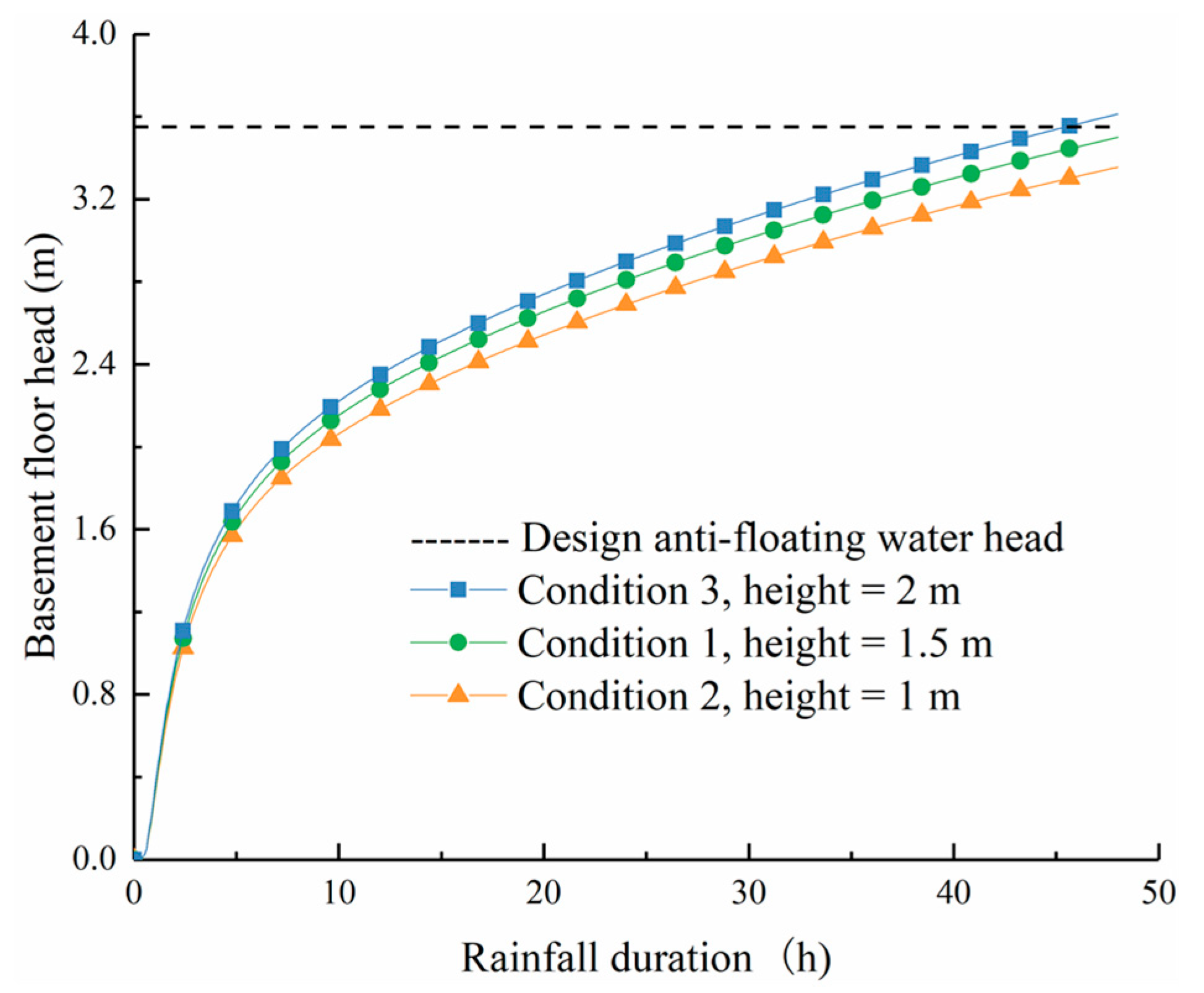
Working conditions 1–3 aim to simulate the influence of the height of the drainage hole layout position from the floor on the anti-floating effect. The relationship between the maximum head of the basement floor and the rainfall duration is shown in Figure 5. The simulation results indicate that during a rainstorm, the buoyancy of the basement floor increases in direct proportion to the height of the drainage hole under the same duration of rainfall. As the duration of rainfall increases, there is a gradual increase in the head difference for each working condition. Specifically, the floor head decreases by 0.15 m (Working conditions 1 and 2) and increases by 0.11 m (Working conditions 1 and 3), respectively, after 48 h.
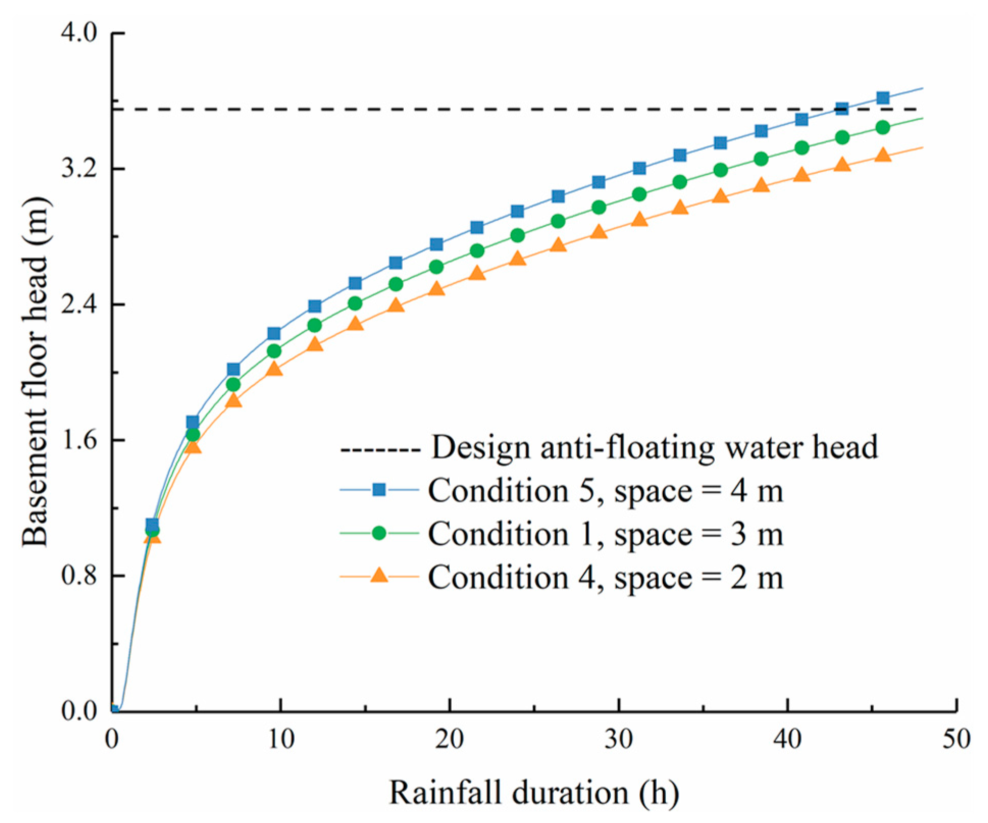
Working conditions 4–5 and Condition 1 are designed to simulate the influence of the spacing of the drainage holes on the anti-floating effect. The relationship between the maximum water head of the basement floor and rainfall duration is shown in Figure 6. The simulation results indicate that, under rainstorm conditions and at the same duration of rainfall, the buoyancy of the basement floor increases in direct proportion to the spacing of drainage holes. As the duration of rainfall increases, there is a gradual increase in the head difference for each working condition. Specifically, the floor head decreases by 0.18 m (Working conditions 1 and 4) and increases by 0.17 m (Working conditions 1 and 5), respectively, after 48 h.
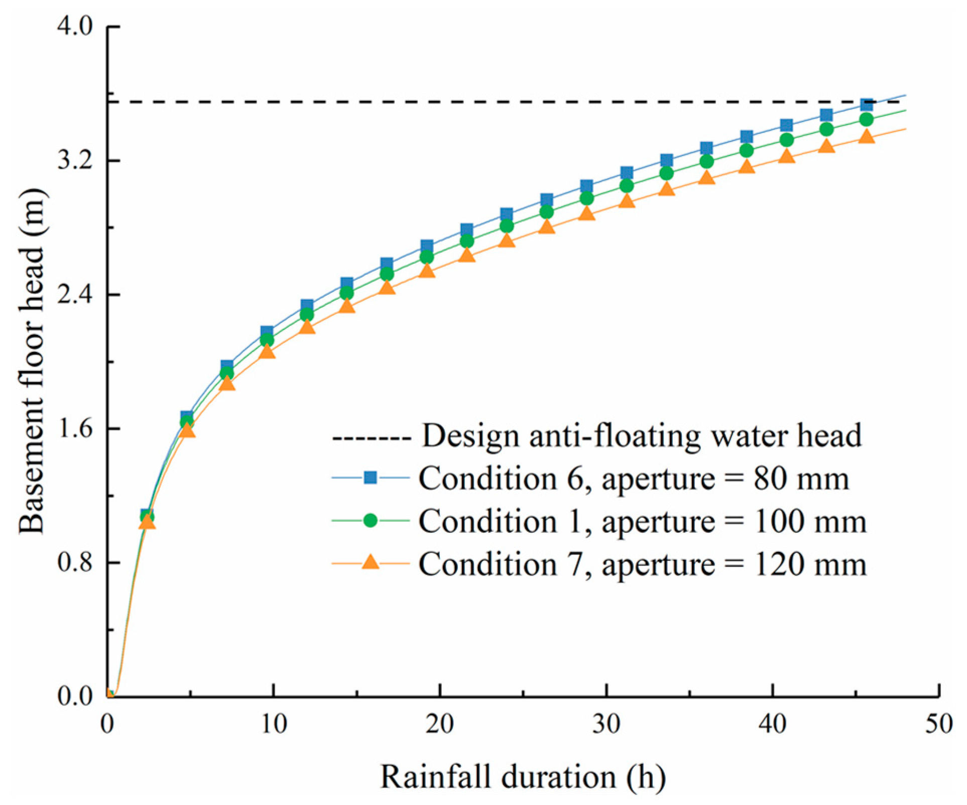
Working conditions 6–7 and Condition 1 are designed to simulate the influence of the aperture of the drainage hole on the anti-floating effect. The relationship between the maximum head of the basement floor and rainfall duration is shown in Figure 7. Under rainstorm conditions and with the same rainfall duration, the buoyancy of the basement floor decreases as the diameter of the drainage hole increases, and the relationship between the two variables is inversely proportional. With the increase in rainfall duration, the floor head difference for each working condition gradually increases, and the floor head increases by 0.09 m (Working conditions 1 and 6) and decreases by 0.11 m (Working conditions 1 and 7), respectively, at 48 h.
According to the seepage law of groundwater, it has been observed that as the height of the drainage hole decreases, there is an increase in the head difference at the same groundwater level, resulting in a higher flow rate of the drainage hole. Hence, the water discharge pressure relief method exhibits a more effective anti-floating effect when the drainage hole is positioned at a lower height. The water passing area of a drainage hole is influenced by its spacing and aperture. By decreasing the spacing or enlarging the aperture of the drainage hole, the water passing area can be increased, thereby enhancing the flow of the drainage hole and improving its anti-floating effect.
It can be seen from Figure 5, Figure 6 and Figure 7 that under rainstorm conditions, the water head of the basement floor increases with the increase in the height and spacing of the drainage holes and decreases with the increase in the aperture of the drainage holes. Among these factors, the height and spacing of the drainage holes are the primary determinants that influence the anti-floating effect. Consequently, in order to ensure the safety and stability of the basement under extreme conditions such as rainstorms, it is essential to prioritize the reduction in the height and spacing of the drainage holes. This measure is beneficial in enhancing the effectiveness of the water discharge pressure relief method in preventing floating.

3.2. Influence of Soil Parameters

Based on Working condition 1, the study primarily focuses on investigating the impact of soil parameters on the effectiveness of the water discharge pressure relief method in preventing floating under rainstorm conditions in Working conditions 8–17. The permeability coefficient of the upper backfill soil, as well as the longitudinal width and permeability coefficient of the lower backfill soil, along with the thickness and permeability coefficient of the cushion, are shown in Table 3. The parameters of drainage hole under each working condition are consistent with those of Condition 1.
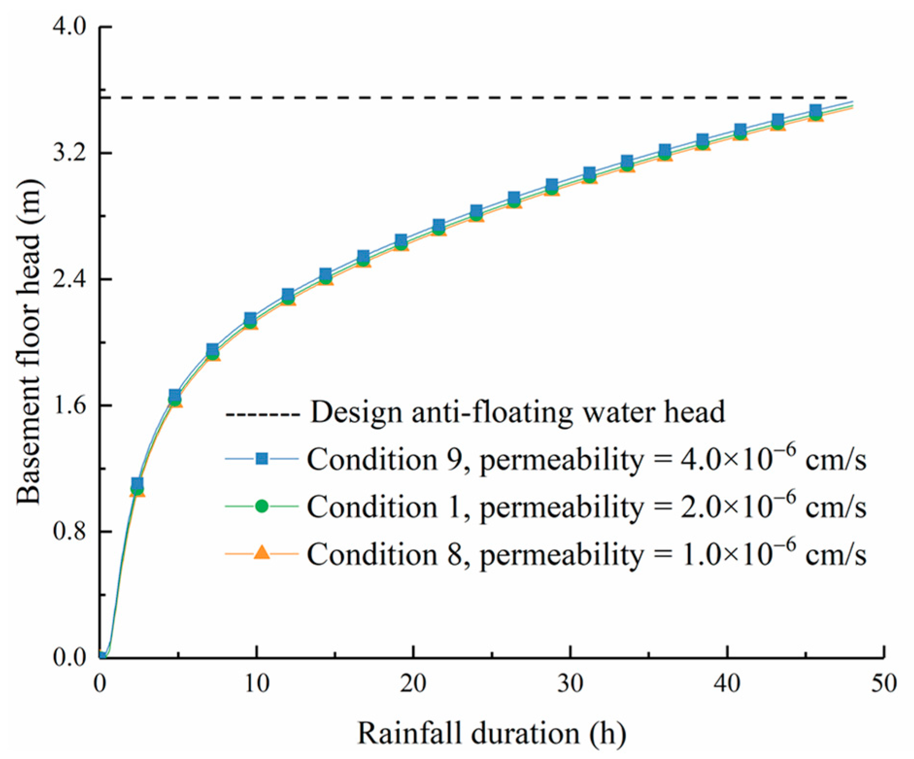
Working conditions 8–9 and Condition 1 are used to simulate the impact of the permeability coefficient of the upper backfill soil on the anti-floating effect. The relationship between the maximum water head of the basement floor and the rainfall duration is shown in Figure 8. Under rainstorm conditions, the water buoyancy of the basement floor is minimally influenced by the permeability coefficient of the upper backfill soil. With the increase in rainfall duration, the floor head difference of each working condition basically does not change. At 48 h, the water head of the basement floor is only reduced by 0.02 m (Conditions 1 and 8) and increased by 0.02 m (Conditions 1 and 9).
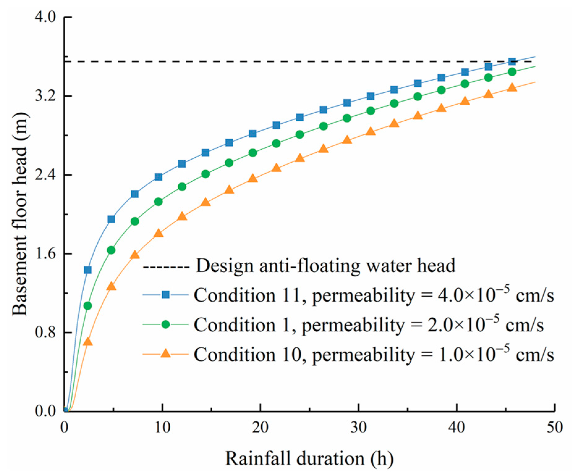
Working conditions 10–11 and Condition 1 simulate the influence of the permeability coefficient of the lower backfill soil on the anti-floating effect. The relationship between the maximum water head of the basement floor and the rainfall duration is shown in Figure 9. It is evident that the water buoyancy of the basement floor increases as the permeability coefficient of the lower backfill soil increases under the same rainfall duration, and the two variables are directly proportional to each other. When the rainfall time is 5 h, the water head difference of the floor under each working condition reaches the maximum. This is because the velocity of the drainage hole increases with the increase in the permeability coefficient of the lower backfill soil, and the head difference gradually decreases with the increase in rainfall duration. At 48 h, the floor head decreases by 0.11 m (Conditions 1 and 10) and increases by 0.09 m (Conditions 1 and 11).
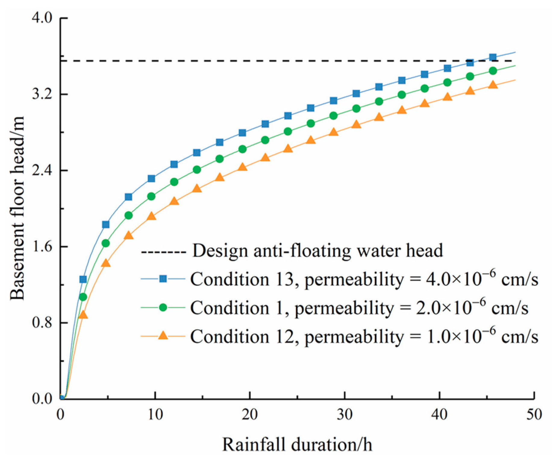
Working conditions 12–13 and Condition 1 are designed to simulate the influence of the permeability coefficient of the cushion on the anti-floating effect. The relationship between the maximum water head of the basement floor and rainfall duration is shown in Figure 10. It can be seen that under rainstorm conditions, the water buoyancy of the basement floor increases in direct proportion to the permeability coefficient of the cushion under the same duration of rainfall. At 48 h, the water head of the floor decreased by 0.16 m (Conditions 1 and 12) and increased by 0.13 m (Conditions 1 and 13), respectively.
Due to the compaction process during backfilling, the permeability of the surface miscellaneous fill is significantly higher than that of the upper backfill. Therefore, the rainwater can easily penetrate the lower backfill and clay through the surface miscellaneous fill. The permeability coefficient of the upper backfill has minimal impact on the floor water head when it is present in a lower interval. Compared to clay with low permeability, the transmission of water buoyancy to the basement floor is facilitated through the lower backfill and the cushion, resulting in a smaller loss of water pressure head during transmission. Consequently, based on the relationship curves between the water head of the basement floor and the rainfall duration under various working conditions shown in Figure 7, Figure 8 and Figure 9, it can be seen that the water head of the floor rises as the permeability coefficient of the lower backfill and cushion increases. However, the permeability coefficient of the upper backfill has minimal impact on the water head. Thus, it can be seen that during the process of backfilling a foundation pit, the addition of admixtures such as curing agents can be considered to decrease the permeability of the backfill soil and cushion. This, in turn, enhances the safety and stability of the basement, particularly in extreme weather conditions like rainstorms.
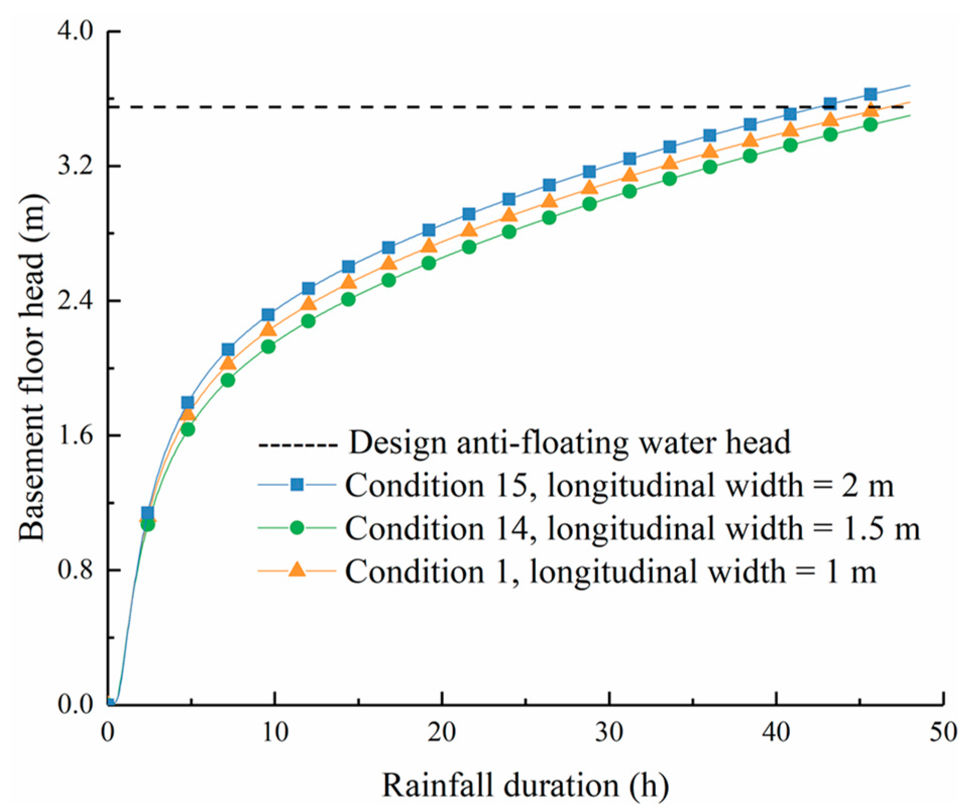
Working conditions 14, 15 and 1 are designed to simulate the influence of the longitudinal width of the lower backfill on the anti-floating effect. The relationship between the maximum water head of the basement floor and the rainfall duration is shown in Figure 11. Under rainstorm conditions, when the rainfall duration is constant, the water buoyancy of the basement floor increases in direct proportion to the longitudinal width of the lower backfill soil. At 48 h, the water head of the basement floor increases by 0.08 m (Conditions 1 and 14) and 0.18 m (Conditions 1 and 15), respectively.
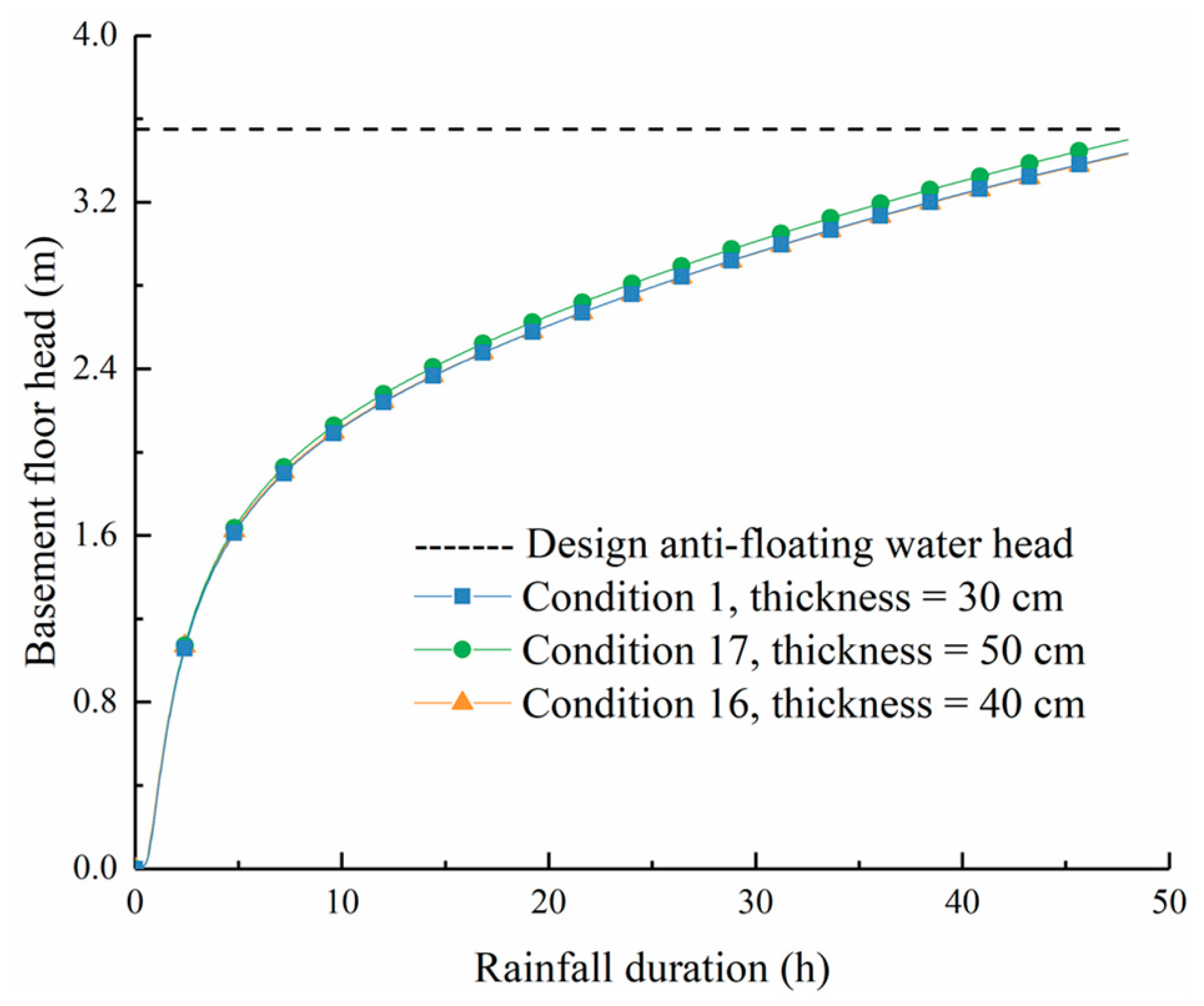
Working conditions 16, 17 and 1 are designed to simulate the impact of cushion thickness on the anti-floating effect. The relationship between the maximum head of the basement floor and rainfall duration is shown in Figure 12. Under rainstorm conditions and the same rainfall duration, the water buoyancy of the basement floor decreases with the increase in the thickness of the cushion, and the two are inversely proportional. At 48 h, the floor head is reduced by 0.07 m (Conditions 1 and 16) and 0.08 m (Conditions 1 and 17), respectively.
Because the permeability of the lower backfill soil is higher than that of the clay, the rainwater is more easily transmitted to the basement floor through the lower backfill soil. Hence, as the longitudinal width of the lower backfill soil increases, there is an increase in the high permeability area, facilitating the transmission of water buoyancy to the basement floor. The thickness of the cushion affects the area of the horizontal transmission of water buoyancy. When the thickness of the cushion is increased, the horizontal transmission of water buoyancy to the center of the basement floor occurs. It is helpful to reduce the concentrated distribution of the water head at the edge of the basement floor. However, as the thickness of the cushion increases, its influence on the anti-floating effect gradually diminishes. In order to ensure the safety and stability of the basement during rainstorms, it is necessary to reduce the longitudinal width of the lower backfill soil and increase the thickness of the cushion layer during the process of foundation pit backfilling.

3.3. Analysis of Seepage and Basement Stability

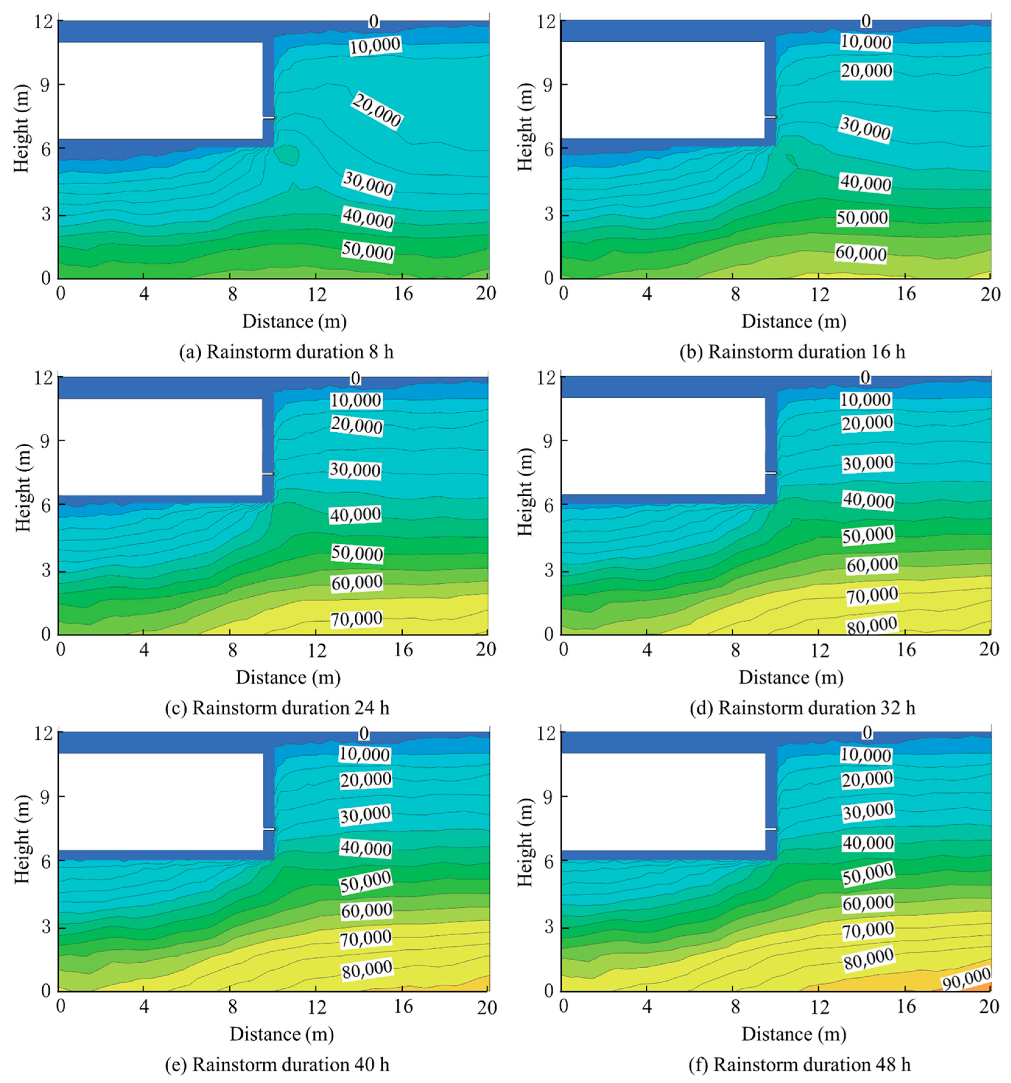
Drainage holes are strategically positioned based on the specific parameters of Working condition 1, and, subsequently, a 48 h rainfall infiltration simulation is conducted for the basement. The numerical simulation results obtained from Flac3d are imported into Tecplot 2021 software for the purpose of generating a contour diagram illustrating the distribution of pore water pressure. The change in pore water pressure around the basement with time is shown in Figure 13.
As shown in Figure 13, due to the impact of rainfall intensity, the runoff is formed on the surface in the early stage of rainfall. The surface soil of the basement exhibits rapid saturation, with negative pore water pressure being observed only in select monitoring areas. The groundwater level experiences a rapid increase due to the continuous rainstorm. The upper layer of soil reaches saturation at 8 h, resulting in the elimination of the negative pore water pressure zone. The groundwater level in the vicinity of the drainage hole exhibits a funnel-shaped pattern, with the bottom water buoyancy reaching 19.64 kPa. Afterward, the increasing rate of floor water buoyancy gradually decelerates, resulting in an increase in maximum water pressure to 34.33 kPa after 48 h.
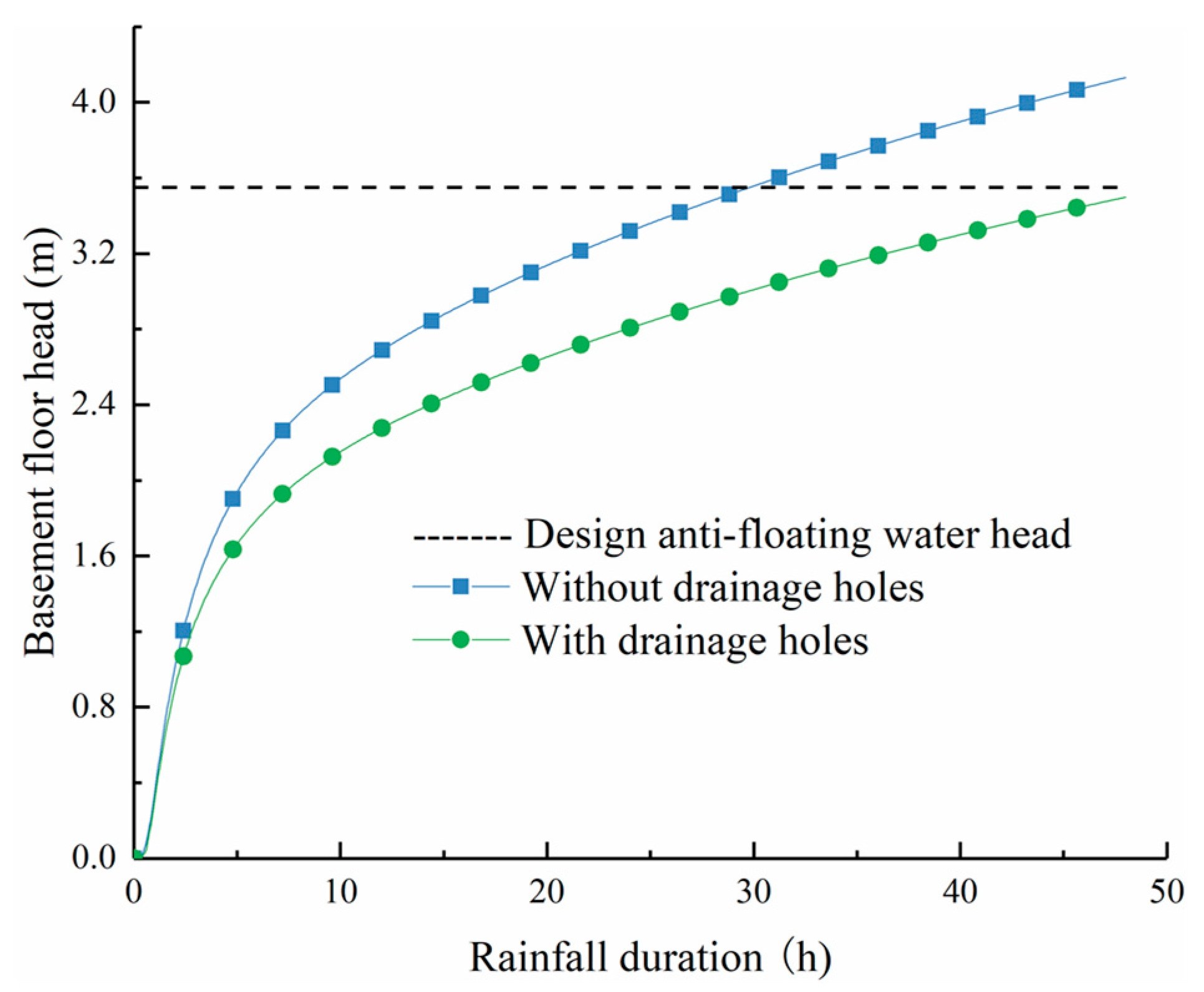
As shown in Figure 14, this paper set the condition that the basement is without drainage holes. The soil parameters of this condition are the same as those in Condition 1. The bottom water head of the basement without drainage holes reaches 4.09 m after 48 h, which exceeds the design anti-floating water head and cannot meet the requirements of the anti-floating stability of the basement. The water head of the basement floor with drainage holes is 3.50 m after 48 h, which can meet the requirements of basement anti-floating stability. It is evident that the utilization of the water discharge pressure relief method can ensure the stability of the basement under rainstorm conditions.

4. Conclusions

  • In this article, Flac3d 6.0 software is used to conduct a numerical simulation study on the basement under rainstorm conditions based on the water discharge pressure relief method. It has been observed that the arrangement of drainage holes can impede the rapid rise of water buoyancy in the basement floor, thereby ensuring the structural stability of the basement under rainstorm conditions.
  • The anti-floating effect of the water discharge pressure relief method under rainstorm conditions is enhanced as the height and spacing of the drainage holes decrease, while it is diminished as the aperture of the drainage hole decreases. The height and spacing of the drainage holes are the main factors affecting the anti-floating effect. Therefore, in order to ensure the safety and stability of the basement during adverse weather conditions like rainstorms, it is crucial to prioritize the reduction in the height and spacing of the drainage holes when designing the basement’s anti-floating system. The recommended spacing for the drainage holes is between 2 m and 3 m. The height of the drainage holes should range from 1 m to 1.5 m. Additionally, the aperture of the drainage holes should not be smaller than 100 mm.
  • Under rainstorm conditions, the water head of the basement floor decreases as the permeability coefficient of the lower backfill and cushion decreases. When the permeability coefficient of the cushion is lower than that of the surrounding clay, it leads to the inflow of groundwater into the bottom of the cushion, resulting in an excessive water head at the bottom of the cushion. When the permeability coefficient of the upper backfill is within a low range, the water head of the basement floor is minimally influenced by the permeability coefficient of the upper backfill. Consequently, it is feasible to compact the backfill soil multiple times during the process of backfilling the foundation pit. In order to reduce the permeability of the backfill soil and the cushion and prevent the use of highly permeable materials, the employment of additives such as soil curing agents can be considered. However, it is important to note that the permeability of the cushion should not be excessively low.
  • The longitudinal width of the lower backfill soil and the thickness of the cushion layer have an impact on the rate of groundwater transmission. In the design of the basement, it is important to control the longitudinal width of the lower backfill soil. The reduction in excavation in the surrounding low-permeability soil layer and the appropriate increase in the thickness of the cushion layer are recommended. The former method has the capability to decelerate the rate at which the water head of the basement floor rises, while the latter approach can enhance the uniformity of the water head distribution across the basement floor.
  • As the rainfall continues, the water head of the basement floor shows a monotonically increasing trend, and the increasing speed is first fast and then slow. The shape of the saturation line near the drainage hole resembles that of a funnel. The basement with drainage holes can remain stable after 48 h of rainstorm. This demonstrates that the water discharge pressure relief method, as proposed, effectively addresses the issue of basement anti-floating and offers valuable guidance for the design of anti-floating measures in basements.

Author Contributions

Conceptualization, L.C. and W.W.; methodology, L.C. and W.W.; software, L.C.; validation, L.C., W.W. and A.B.; formal analysis, L.C. and W.W.; investigation, L.C.; resources, L.C.; data curation, L.C. and W.W.; writing—original draft preparation, L.C.; writing—review and editing, L.C., W.W. and A.B.; visualization, L.C. and W.W.; supervision, L.C., W.W. and A.B.; project administration, L.C. and W.W.; funding acquisition, L.C. and W.W. All authors have read and agreed to the published version of the manuscript.

Funding

This research was funded by National Key R&D Program of China (No. 2022YFC2903901) and The National Key Research and Development Program of China–2023 Key Special Project (No. 2023YFC2907400). The support is gratefully acknowledged. Any opinions, findings, conclusions or recommendations expressed in this study are those of the authors and do not necessarily reflect the views of the sponsoring agencies.

Data Availability Statement

All data, models or codes that support the findings of this study are available from the corresponding author upon reasonable request.

Conflicts of Interest

The authors declare no conflict of interest. The funders had no role in the design of the study; in the collection, analyses or interpretation of data; in the writing of the manuscript; or in the decision to publish the results.

References

  1. Jiang, W.Z.; Tan, Y. Overview on failures of urban underground infrastructures in complex geological conditions due to heavy rainfall in China during 1994–2018. Sustain. Cities Soc. 2022, 76, 103509. [Google Scholar] [CrossRef]
  2. Jiang, C.H.; Lai, Y.X. An example of using well point precipitation and ground loading to treat basement uplift. Geotech. Found. 1999, 1, 49–51. [Google Scholar]
  3. Jia, Y.G.; Fei, Y.; Wu, G.Y. Analysis and treatment of a floating arch project accident in a large basement structure. Constr. Tech. 2016, 45, 48–52. [Google Scholar]
  4. Zhang, X.P.; Li, X.; Cai, Y.H. Discussion on the impact of the “7.20” rainstorm in zhengzhou on foundation pit construction. In Proceedings of the 2021 National Engineering Construction Industry Construction Technology Exchange Conference, Bhimavaram, India, 16–17 October 2021; Volume 1, pp. 287–289. [Google Scholar]
  5. Song, L.J.; Pei, J.J. Treatment and analysis on floating accident of an underground civil air defence project. Eng. Constr. 2022, 54, 74–78. [Google Scholar]
  6. Wang, H.; Ying, X.L.; Luo, Y.; Wu, J.L.; Liu, Y.H. Investigation and cause analysis of local floating accident on the second floor of a multi-functional building. Build. Struct. 2022, 52, 2273–2277. [Google Scholar]
  7. Maulik, R.A.; Upadhyaya, D.S.; Panchal, S.L. Preventation of hydrostatic uplift pressure underneath of basement floor slab in high water table area. Int. J. Futur. Trends Eng. Technol. 2014, 1, 72–75. [Google Scholar]
  8. Bikçe, M.; Örnek, M.; Cansız, Ö.F. The effect of buoyancy force on structural damage: A case study. Eng. Fail. Anal. 2018, 92, 553–565. [Google Scholar] [CrossRef]
  9. Zhang, X.W.; Tang, X.W.; Shao, Q.; Bai, X. The uplift behavior of large underground structures in liquefied field. Appl. Mech. Mater. 2011, 90, 2112–2118. [Google Scholar] [CrossRef]
  10. He, L.; He, Z. Analysis of floating effect of groundwater on built underground structure. IOP Conf. Ser. Earth Environ. Sci. 2021, 784, 012030. [Google Scholar] [CrossRef]
  11. Jiang, K.W. Anti-floating design of single-story underground garage. Build. Struct. 2011, 41, 677–679. [Google Scholar]
  12. Li, G.S. Discussion on water buoyancy in basement design. Build. Struct. 2018, 48, 117–123. [Google Scholar]
  13. Srivastava, A.; Babu, G.L.S. Uplift capacity and performance assessment of anchor piles installed to basement raft. Electron. J. Geotech. Eng. 2012, 17, 1173–1187. [Google Scholar]
  14. Kong, D.Z.; Guan, Y.A.; Yuan, H. Study on the anti-floating water level of the underground structure’s comprehensive anti-floating. Structures 2023, 56, 104921. [Google Scholar] [CrossRef]
  15. Wong, I.H. Methods of resisting hydrostatic uplift in substructures. Tunn. Undergr. Space Technol. 2001, 16, 77–86. [Google Scholar] [CrossRef]
  16. Ni, P.P.; Mei, G.X.; Zhao, Y.L. Antiflotation design for water tank using pressure relief technique. Mar. Georesour Geotechnol. 2018, 36, 471–483. [Google Scholar] [CrossRef]
  17. El-Razek, M.A.; Elelai, M.M.A. Effect of drainage gallery dimensions on the uplift force of a gravity dam. Lowl. Technol. Int. J. 2002, 4, 43–50. [Google Scholar]
  18. Li, P.; Liu, H.; Zhao, Y. A bottom-to-up drainage and water pressure reduction system for railway tunnels. Tunn. Undergr. Space Technol. 2018, 81, 296–305. [Google Scholar] [CrossRef]
  19. Kolymbas, D.; Wagner, P. Groundwater ingress to tunnels—The exact analytical solution. Tunn. Undergr. Space Technol. 2007, 22, 23–27. [Google Scholar] [CrossRef]
  20. Luo, G.Y.; Ming, J. A new anti-float method for riverside underground structures: Drainage corridor combined with uplift piles or uplift anchors. Rock Soil Mech. 2020, 41, 3730–3739. [Google Scholar]
  21. Zhang, X.Y.; Liang, Q.L. Application of Hydrostatic Pressure Release Technology in Deep Underground Engineering. Constr. Technol. 2022, 51, 85–88. [Google Scholar]
  22. Wang, M.J.; He, S.-M. Application of partial bonding prestressed anti-floating pile and leakage treatment. Archit. Technol. 2014, 45, 623–625. [Google Scholar]
  23. Mao, Z.; Guo, H.; Wu, Y.; Wang, E.; Li, X. Development of a New Uplift Pile with Prestressed Semi-Bonded Composite Anchor. Buildings 2022, 12, 1478. [Google Scholar] [CrossRef]
  24. Liu, H.; Song, E. Working mechanism of cutoff walls in reducing uplift of large underground structures induced by soil liquefaction. Comput. Geotech. 2006, 33, 209–221. [Google Scholar] [CrossRef]
  25. Zhu, D.F. Research on key issues of underground structure drainage, decompression, and anti-floatation method for seepage control. Ph.D. Thesis, South China Technology University, Guangzhou, China, 2019. [Google Scholar]
  26. Zhang, J.X. The application of water release and decompression scheme in the anti-floating design of underground reservoirs —Taking the Wuhan New City Puyue Mendi Project as an Example. Eng. Technol. Res. 2020, 5, 19–20. [Google Scholar]
  27. Xu, Z.; Lai, Y.; Mei, G.X. Numerical simulation of water-discharging pressure-relief technology on anti-floating of swimming pools. Chin. J. Geotech. Eng. 2013, 35, 451–455. [Google Scholar]
  28. Gan, Q.; Yang, B.J.; Liu, W. Discussion and application of the water-discharging pressure relief technology in the anti-floating design of basement. Build. Struct. 2016, 46, 86–90. [Google Scholar]
  29. Yang, B.J.; Li, Y.P.; Gan, Q. Orthogonal analysis of influencing factors of anti-floating effect of water discharge and decompression method. J. Yangtze River Sci. Res. Inst. 2016, 33, 121–127. [Google Scholar]
  30. Chen, Y.M. FLAC/FLAC3D Basics and Engineering Examples; Water Conservancy and Hydropower Press: Beijing, China, 2009. [Google Scholar]
  31. Chen, Y.F.; Zhou, C.B.; Zheng, H. A numerical solution to seepage problems with complex drainage systems. Comput. Geotech. 2008, 35, 383–393. [Google Scholar] [CrossRef]
  32. Yu, J.; Li, D.K. Analytical study on the seepage field of different drainage and pressure relief options for tunnels in high water-rich areas. Tunn. Undergr. Space Technol. 2023, 134, 10518. [Google Scholar] [CrossRef]
  33. Ahmed, A.A.; Bazaraa, A.S. Three-dimensional analysis of seepage below and around hydraulic structures. J. Hydrol. Eng. 2009, 14, 243–247. [Google Scholar] [CrossRef]
  34. Yuan, Y. A Method for Anti-Floating of Underground Buildings: China. ZL200710052439.9, 10 October 2010. [Google Scholar]
  35. Veiskarami, M.; Zanj, A. Stability of sheet-pile walls subjected to seepage flow by slip lines and finite elements. Géotechnique 2014, 64, 759–775. [Google Scholar] [CrossRef]
  36. Song, L.H.; Kang, X.; Mei, G.X. Buoyancy force on shallow foundations in clayey soil: An experimental investigation based on the “Half Interval Search”. Ocean. Eng. 2017, 129, 637–641. [Google Scholar] [CrossRef]
  37. Van Genuchten, M.T. A closed-form equation for predicting the hydraulic conductivity of unsaturated Soils. Soil. Sci. Am. J. 1980, 44, 892–898. [Google Scholar] [CrossRef]
  38. GB50007-2011; Code for Design of Building Foundation. Architecture & Building Press: Beijing, China, 2021.
  39. Yang, F.; Yang, P. Research on characteristics of rainfall at Zhuzhou hydrological station in Xiangjiang river in recent 60 Years. Pap. River 2020, 41, 92–97. [Google Scholar]
  40. GB50014-2021; Outdoor drainage design standards. Architecture & Building Press: Beijing, China, 2021.
  41. Jiang, Z.M.; Xiong, X.H.; Zeng, L. Analysis of unsaturated rainfall infiltration in slope based on FLAC~(3D) platform. Soil Mech. 2014, 35, 855–861. [Google Scholar]
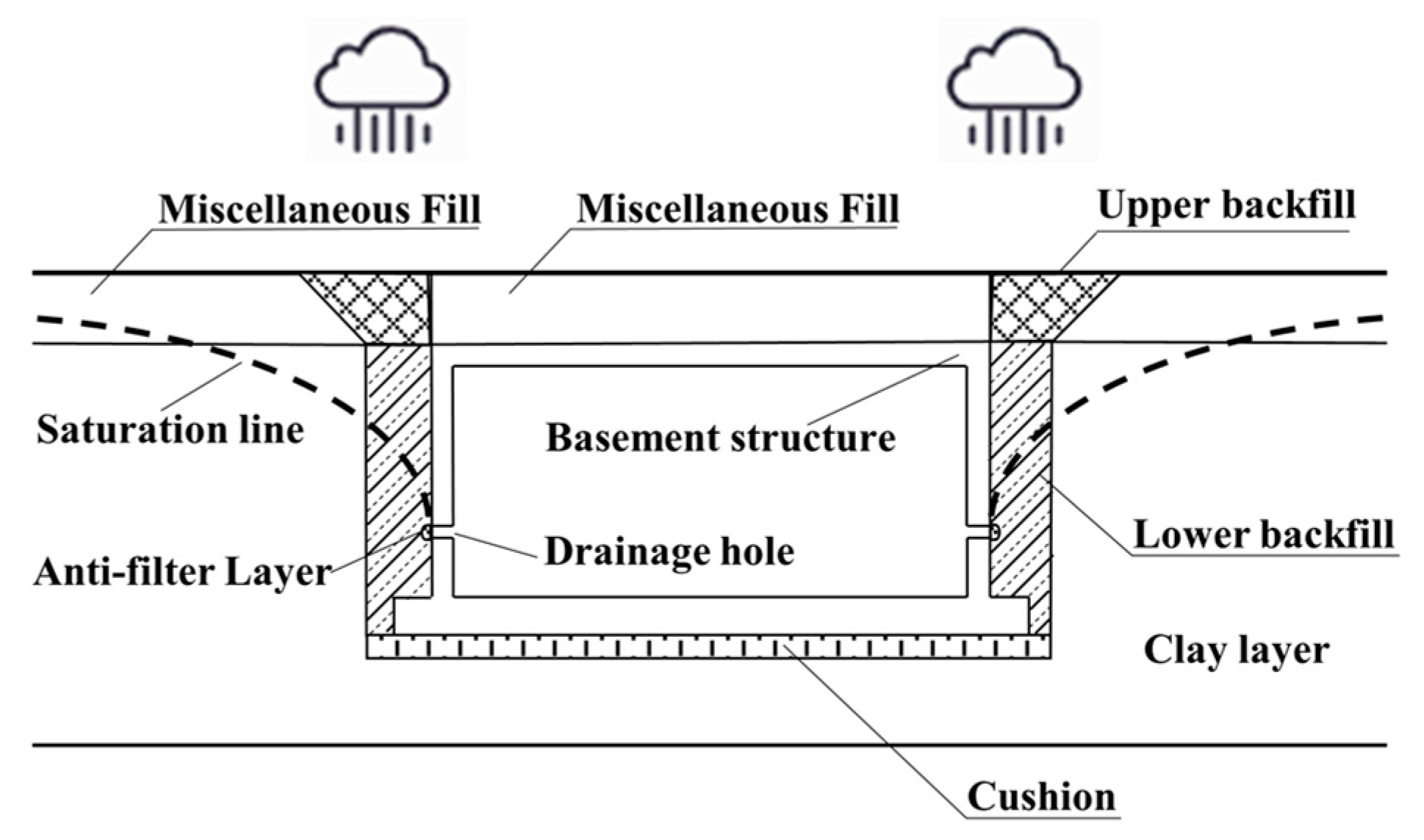
Figure 1. Schematic diagram of the water discharge pressure relief method.
Buildings 13 02772 g001
Figure 2. Chart for calculation of unsaturated coefficient of permeability.
Buildings 13 02772 g002
Figure 3. Cross-sectional view of the model.
Buildings 13 02772 g003
Figure 4. Three-dimensional calculation model.
Buildings 13 02772 g004
Figure 5. Relationship between the basement floor head and rainfall duration with different drainage hole heights (Working conditions 1 to 3).
Buildings 13 02772 g005
Figure 6. Relationship between the basement floor head and rainfall duration with different drainage hole space (Working conditions 1, 4 and 5).
Buildings 13 02772 g006
Figure 7. Relationship between the basement floor head and rainfall duration with different drainage hole apertures (Working conditions 1, 6 and 7).
Buildings 13 02772 g007
Figure 8. Relationship between the basement floor head and rainfall duration under different permeability coefficient of upper backfill (Working conditions 1, 8 and 9).
Buildings 13 02772 g008
Figure 9. Relationship between the basement floor head and rainfall duration under different permeability coefficients of lower backfill (Working conditions 1, 10 and 11).
Buildings 13 02772 g009
Figure 10. Relationship between the basement floor head and rainfall duration under different permeability coefficients of cushion (Working conditions 1, 12 and 13).
Buildings 13 02772 g010
Figure 11. Relationship between the basement floor head and rainfall duration under different longitudinal widths of the lower backfill (Working conditions 1, 14 and 15).
Buildings 13 02772 g011
Figure 12. Relationship between the basement floor head and rainfall duration under different cushion thicknesses (Working conditions 1, 16 and 17).
Buildings 13 02772 g012
Figure 13. Changes in pore water pressure around the basement during the continuous 48 h rainstorm.
Buildings 13 02772 g013
Figure 14. Relationship between the basement floor head and rainfall duration.
Buildings 13 02772 g014
Table 1. Basic parameters of soil strata.
Soil Layer Soil TypeSoil
Thickness (m)
Unit Weight
(kN/m3)
Elastic Modulus (MPa)Internal Friction
Angle (°)
Cohesion (kPa)Saturated Permeability Coefficient (cm/s)Poisson’s Ratio
Miscellaneous FillSandy soil218.45.2882.0 × 10−40.2
Upper backfillclay218.56.388.52.0 × 10−60.21
Lower backfillSandy soil and clay418.56.588.52.0 × 10−50.21
CushionClay0.318.68.01692.0 × 10−60.25
Clay layerClay1018.326.016251.0 × 10−60.25
Table 2. Parameter values and simulated results under Working conditions 1 to 7.
Condition NumberInfluence Factor
Height of Drainage Hole (m)Spacing of Drainage Hole (m)Aperture of Drainage Hole (mm)Maximum Head of Basement Floor after 48 h (m)
11.531003.50
2131003.35
3231003.61
41.521003.32
51.541003.67
61.53803.59
71.531203.39
Table 3. Parameter values of soils and simulating results under Working conditions 8 to 17.
Condition NumberPermeability Coefficient of Upper Backfill (cm/s)Permeability Coefficient of Lower Backfill (cm/s)Permeability Coefficient of Cushion (cm/s)Permeability Coefficient of Clay Layer (cm/s)Longitudinal Width of Lower Backfill (m)Cushion Thickness (cm)Maximum Head of Basement Floor after 48 h (m)
12.0 × 10−62.0 × 10−52.0 × 10−61.0 × 10−61.0303.50
81.0 × 10−62.0 × 10−52.0 × 10−61.0 × 10−61.0303.48
94.0 × 10−62.0 × 10−52.0 × 10−61.0 × 10−61.0303.52
102.0 × 10−61.0 × 10−52.0 × 10−61.0 × 10−61.0303.39
112.0 × 10−64.0 × 10−52.0 × 10−61.0 × 10−61.0303.59
122.0 × 10−62.0 × 10−51.0 × 10−61.0 × 10−61.0303.34
132.0 × 10−62.0 × 10−54.0 × 10−61.0 × 10−61.0303.63
142.0 × 10−62.0 × 10−52.0 × 10−61.0 × 10−61.5303.58
152.0 × 10−62.0 × 10−52.0 × 10−61.0 × 10−62.0303.68
162.0 × 10−62.0 × 10−52.0 × 10−61.0 × 10−61.0403.43
172.0 × 10−62.0 × 10−52.0 × 10−61.0 × 10−61.0503.42
Disclaimer/Publisher’s Note: The statements, opinions and data contained in all publications are solely those of the individual author(s) and contributor(s) and not of MDPI and/or the editor(s). MDPI and/or the editor(s) disclaim responsibility for any injury to people or property resulting from any ideas, methods, instructions or products referred to in the content.