Article

Investigation of Passive Pile Groups’ Responses Induced by Combined Surcharge-Induced and Excavation-Induced Horizontal Soil Loading

College of Civil Engineering, Tongji University, Shanghai 200092, China
*
Author to whom correspondence should be addressed.
Buildings 2023, 13(11), 2775; https://doi.org/10.3390/buildings13112775
Submission received: 17 September 2023 / Revised: 23 October 2023 / Accepted: 2 November 2023 / Published: 3 November 2023
(This article belongs to the Section Building Structures)

Abstract

:
Excessive lateral forces and the deformation of pile groups caused by adjacent surcharge loading and excavation can potentially lead to the failure or collapse of nearby pile foundations. This paper presents a simplified analytical method to investigate the lateral displacement of passive pile groups caused by combined surcharge-induced and excavation-induced horizontal soil loading and validates it by utilizing two published centrifuge tests and numerical modeling. Firstly, the passive load resulting from surcharge-induced horizontal soil loading is determined using the improved formula of Boussinesq and the theory of local plastic deformation. The additional horizontal force exerted on the pile axis subjected to excavation-induced horizontal soil loading is also taken into account using the Mindlin solution. Furthermore, the shielding effect between pile groups is also proposed to analyze the response of a laterally loaded pile group due to excavation unloading. Secondly, according to the Pasternak foundation model of soil–pile interaction, the equilibrium differential equations are solved by the finite difference method. Finally, parametric analyses are undertaken to evaluate the behavior of different constraints on the pile head and surcharge procedure. The results demonstrate that the capped-head pile groups can provide greater restraint compared to the free-head groups for the lateral displacement of pile groups. The front pile experiences greater forces than the rear one in passive pile groups as a result of the smaller soil pressure on the rear pile. Additionally, increasing the horizontal stiffness of the capped head with fully fixed ends can significantly decrease the horizontal deformation of the pile groups.

1. Introduction

With the rapid expansion of the transportation network, an increasing number of pile foundations are induced by passive load. The primary cause of the collapse of the Baosteel warehouse in Shanghai has been revealed as long-term repetitive loading and unloading, which resulted in excessive lateral displacement and the accumulated displacement of both the soil and pile foundations. And the collapse of a 13-story residential building south of Dingpu River in Shanghai has indicated that the horizontal movement of the soil induced by external factors indirectly affects the lateral loading on the pile, which caused a severe impact on adjacent pile foundations [1,2,3]. Therefore, it is crucial to fully comprehend the interaction between passive piles and the surrounding soil. In areas of soft soil, it is common to excavate on one side of an existing pile foundation while simultaneously applying surcharge loading on the other side. At present, there is a limited amount of research that examines the characteristics and mechanisms of the interaction between passive pile groups and surrounding soil induced by surcharge loading and excavation. Additionally, there is also a lack of comprehensive analysis methods, specific design theory, and standard guidelines for reference, which poses a significant challenge to the safe design, economic protection, and development of the coastal urban infrastructure engineering of pile foundations in soft soil areas, particularly when dealing with combined surcharge-induced and excavation-induced horizontal soil loading. Therefore, investigating the horizontal deformation of passive pile groups caused by combined surcharge-induced and excavation-induced horizontal soil loading is of some practical significance.
The effect of surcharge or excavation unloading on neighboring pile groups has been widely discussed in recent decades [4]. Poulos et al. [5] adopted a two-stage method for the single pile caused by typical soil movement and used the Mindlin solution for lateral displacement and forces of the pile. Liang et al. [6,7] presented an analytical method for the response of the single pile and pile groups caused by horizontal soil loading, and the shielding effect of pile groups based on the soil movement moderation factor was proposed for the pile foundations. Yang et al. [8] carried out numerical modeling with the finite element method to investigate the influence of soil parameters for the response of a single pile and without piles subjected to surcharge loading, respectively. Feng et al. [9] proposed a research method to study the vertical and horizontal loading characteristics of bridge pile foundations under surcharge loading, taking into account the Boussinesq solution and the Mindlin displacement solution. Zhu et al. [10] obtained passive pile loading based on the improved solution of Boussinesq and the Ito theory of local plastic deformation, and established a series of differential equations for the passive piles caused by surcharge loading. Zheng et al. [11] and Li and Zheng [12] investigated the influence of excavation on nearby pile foundation deformations using the PLAXIS 3D finite element software and the hardening soil with small-strain stiffness constitutive model (HSS), and analyzed various deformation forms of support structures, deformations of pile foundations, taking into account the initial settlement caused by foundations self-weight, corner effects of excavations, and the influence of foundations with different stiffness. Finno et al. [13] measured and analyzed the displacement and bending moment of the pile groups beneath the frame structure during the excavation process, and also conducted a numerical simulation using the plane finite element method. Based on the three-parameter foundation model and the finite difference method, Yang et al. [14] presented the lateral displacement of a single passive pile under combined surcharge-induced and excavation-induced horizontal soil loading.
This paper proposes a simplified analytical method to investigate the lateral displacement of passive pile groups caused by combined surcharge-induced and excavation-induced horizontal soil loading, and validates it by utilizing two published centrifuge tests and numerical modeling. Firstly, the passive load resulting from surcharge-induced horizontal soil loading is determined using the improved formula of Boussinesq and the theory of local plastic deformation, taking into account the critical earth pressure with time. Furthermore, the shielding effect between pile groups is also proposed to analyze the response of a laterally loaded pile group due to excavation unloading. Secondly, based on the Pasternak foundation model of soil–pile interaction, the equilibrium differential equations are solved using the finite difference method. Finally, parametric analyses are undertaken to evaluate the behavior of different constraints on the pile head and surcharge procedure. The results demonstrate that the capped-head pile groups can provide greater restraint compared to the free-head groups for the lateral displacement of pile groups. The front pile experiences greater forces than the rear one in the passive pile groups as a result of the smaller soil pressure on the rear pile. Additionally, increasing the horizontal stiffness of the capped-head pile groups with fully fixed ends can significantly decrease the horizontal deformation of the pile groups.

2. Analysis Method

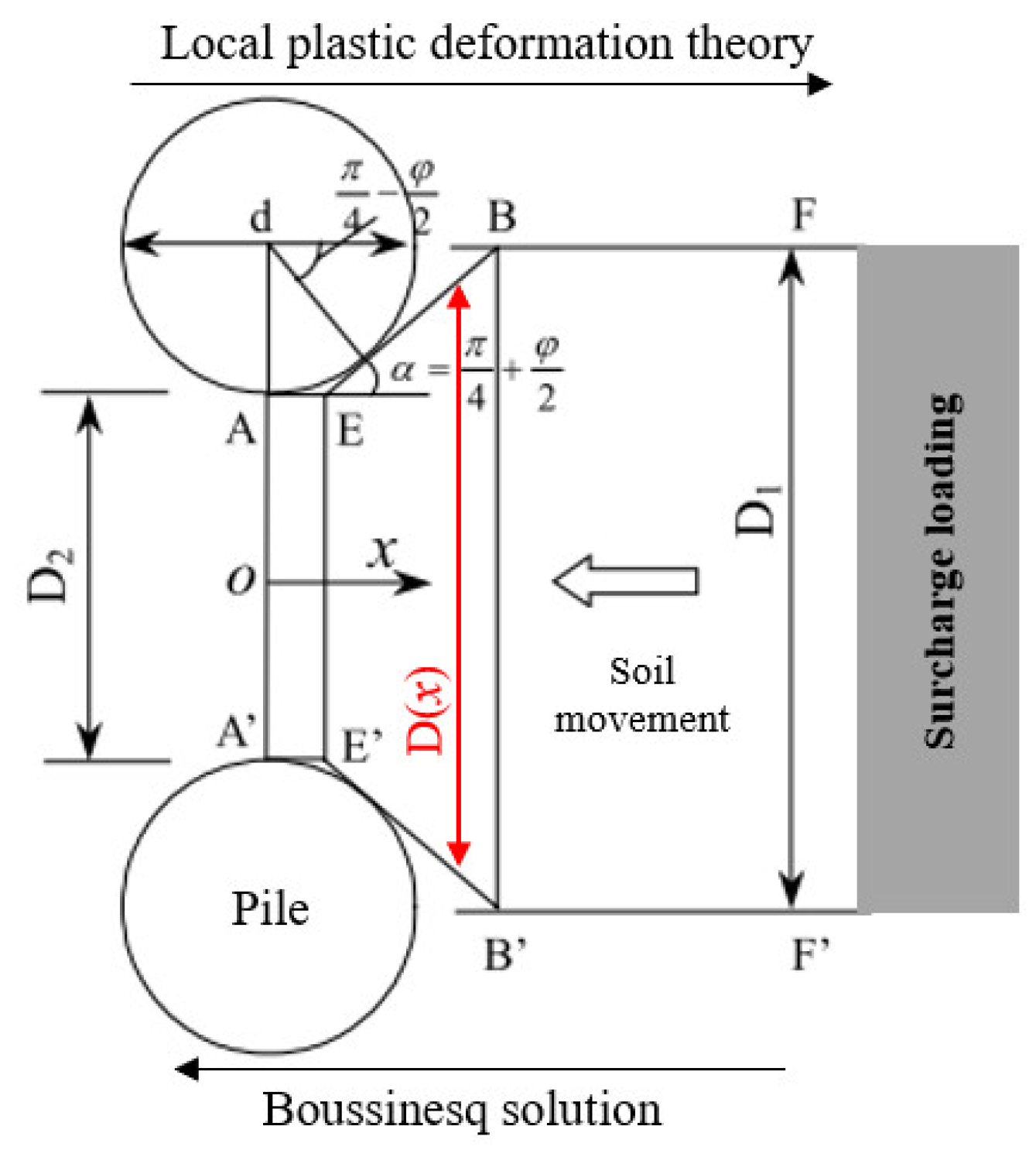
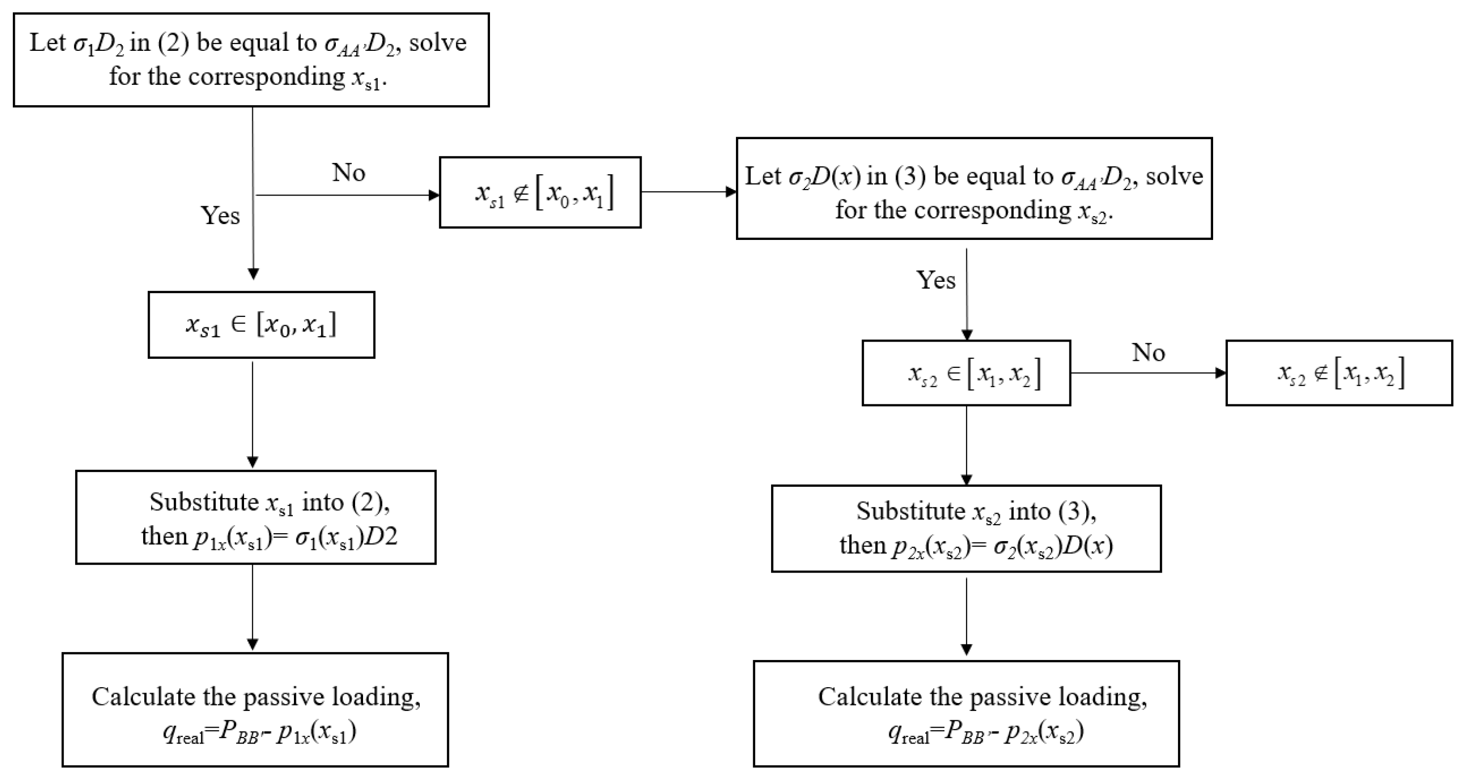
2.1. The Passive Load of Pile Groups Due to Surcharge-Induced Horizontal Soil Loading

According to the improved formula of Boussinesq and the theory of local plastic deformation (Figure 1), taking into account the critical earth pressure with time t, the horizontal stresses at the AA’ face, AEEA’ and BEEB’ place per unit area are proposed, respectively:
σ h A A = σ x , z = 0 = { σ h a = γ z K a 2 c K a σ h , t = σ h 0 + e a t ( σ h a σ h 0 ) σ h 0 = γ z K 0 Active   earth   pressure   state Critical   earth   pressure   at   any   moment Static   earth   pressure   state
where Ka and σha denote the active earth pressure coefficient and active pressure, respectively. K0 and σh0 denote the static earth pressure coefficient and static pressure, respectively.
σ x , A E E A = σ 1 = { N φ tan φ ( N φ + N φ 1 / 2 tan φ 1 ) exp ( N φ tan φ D 1 D 2 D 2 tan ( π 8 + φ 4 ) ) { ( D D 1 ) N φ + N φ 1 / 2 tan φ 1 [ p sd ( N φ + N φ 1 / 2 tan φ 1 ) + c ( 2 tan φ + 2 N φ 1 / 2 + N φ 1 / 2 ) ] c ( 2 tan φ + 2 N φ 1 / 2 + N φ 1 / 2 ) } + c ( 1 + 2 N φ 1 / 2 tan φ ) exp ( N φ tan φ D 1 D 2 D 2 tan ( π 8 + φ 4 ) ) } exp ( 2 N φ tan φ D 2 x ) N φ tan φ c ( 1 + 2 N φ 1 / 2 tan φ ) N φ tan φ
σ x , B E E B = σ 2 = 1 N φ + N φ 1 / 2 tan φ 1 { ( D D 1 ) N φ + N φ 1 / 2 tan φ 1 [ p sd ( N φ + N φ 1 / 2 tan φ 1 ) + c ( 2 tan φ + 2 N φ 1 / 2 + N φ 1 / 2 ) ] c ( 2 tan φ + 2 N φ 1 / 2 + N φ 1 / 2 ) }
where c and φ denote the parameters of the degree of consolidation at any moment; psd = ps + σhAA, psd denotes the lateral stress on the BB’ face, and ps calculates the improved formula of Boussinesq theory of elasticity.
In order to calculate the passive load on passive pile groups, the position of equilibrium is determined by the horizontal thrust loading from both the lateral stress on the AA’ side and the lateral stress on the BB’ side, which act as controlled boundary conditions in the plastic zone AEBBEA’ due to the soil arching effect. Therefore, the procedure for the passive load of passive pile groups is demonstrated as follows (Figure 2):

2.2. The Total Additional Lateral Forces of Pile Groups Caused by Excavation-Induced Horizontal Soil Loading

According to the Mindlin solutions [15], the integral expression of vertical stress at the bottom and three horizontal stresses at the sidewalls on the single pile caused by excavation-induced horizontal soil loading referred to the derivation process in the literature [16].
The shielding effect was the most important method to deal with the pile–pile interaction in the pile groups. Liang et al. [7], Huang et al. [17], and Ong et al. [18] adopted the shielding effect using the Mindlin solution for pile groups. Due to the complexity of the interaction, the additional horizontal force equation derived from the shielding effect refers to Li et al. [19].
Therefore, the total additional lateral forces of a single pile in pile groups caused by excavation-induced horizontal soil loading could be estimated through adding the additional lateral forces of a single pile and the additional lateral force equation derived from the shielding effect.

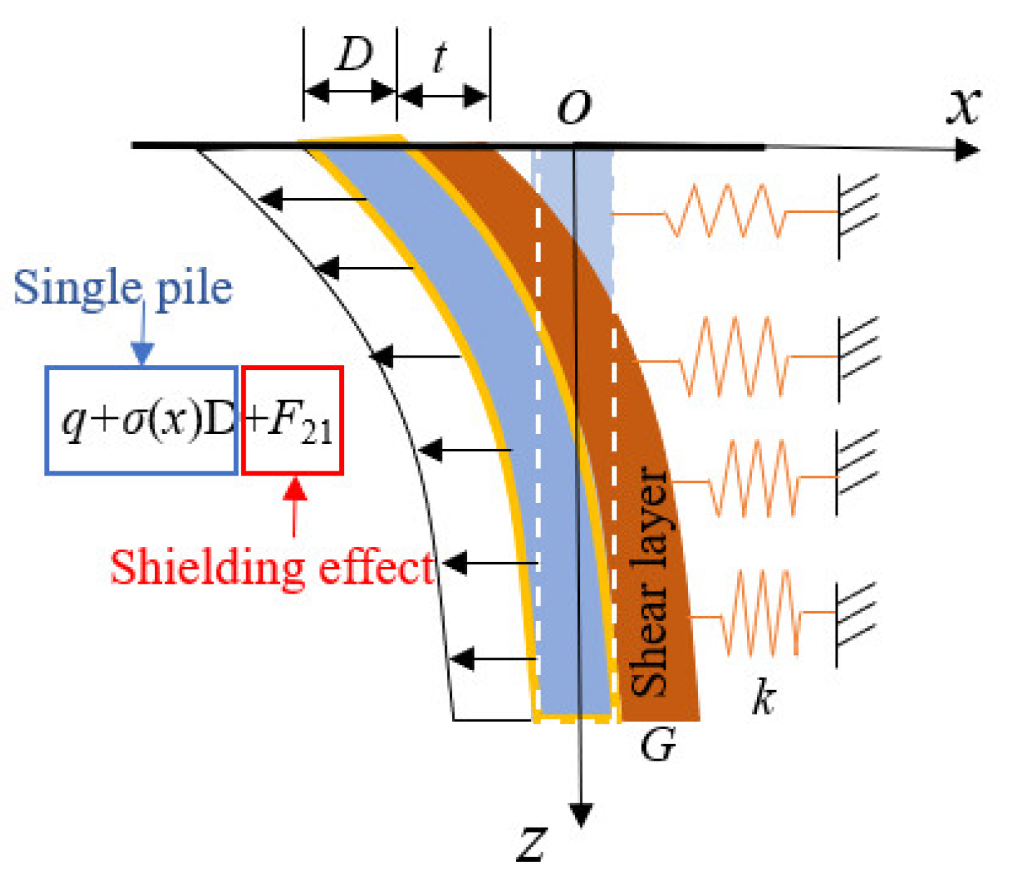
2.3. Two-Parameter Foundation Model
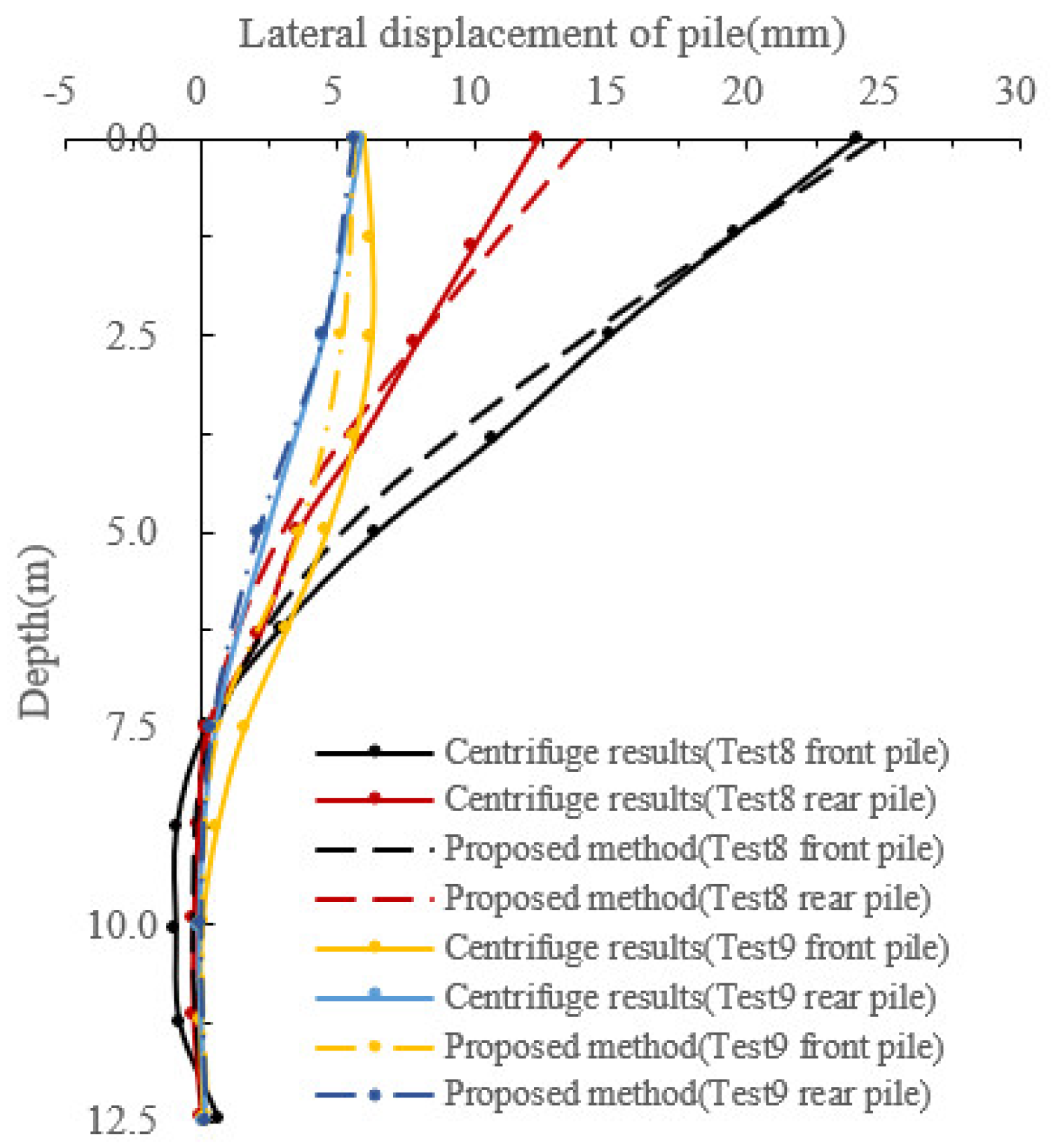
In the theory of elastic foundation beams, the most commonly used is the Winkler foundation model. The model assumes that the foundation consists of a series of independent springs; however, it does not take into account the shear stiffness of the soil. To address this issue, some researchers have introduced a second parameter to reflect the shear interaction between the springs, and the two-parameter Pasternak foundation model [20] is widely used for this purpose (Figure 3).
p = k y G d 2 y d x 2
where k is suggested by Vesic [21], and used by Huang et al. [17], Ong et al. [18] and Goh et al. [22]; G denotes the shear stiffness, suggested by Tanahashi et al. [23] and Shi et al. [24]. In the plastic phase of soft clay, the ultimate pressure is pu = 9 CuD, and Cu represents the undrained shear strength in soft clay and D denotes the diameter of the pile.
Taking into account the pile groups under the combined surcharge-induced and excavation-induced horizontal soil loading, the governing equilibrium differential equation is provided as follows:
E I d 4 y d x 4 + Q d 2 y d x 2 G D d 2 y d x 2 + k D y = q + σ x D + F 21
where Q denotes the axial loading; q represents the passive load of pile groups induced by surcharge-induced horizontal soil loading; σxD denotes the additional lateral forces of a single pile; and F21 represents the additional lateral force equation derived from the shielding effect.
The finite difference approach for solving the above Equation (5) is also presented:
α y i 2 + β y i 1 + λ y i + β y i + 1 + α y i + 2 = σ x i + q i + F 21 D
[ α β λ ] = [ 1 0 0 4 1 0 6 2 1 ] { E I D h 4 Q G D D h 2 k }
Furthermore, according to the finite difference method, the equations are shown as follows:
M i = E I h 2 ( y i + 1 2 y i + y i 1 )
( q + σ x D + F 21 p D ) i = E I h 4 ( y i + 2 4 y i + 1 + 6 y i 4 y i 1 + y i 2 ) + Q G D h 2 ( y i + 1 2 y i + y i 1 )
Under the condition of the constraints on pile groups, such as free head, free head with a free-fixed end, free head with a translation-fixed head, capped head with fully fixed ends, etc., the total horizontal deformation of passive pile groups caused by combined loading-induced and unloading-induced horizontal soil loading can be calculated.

3. Validation

3.1. The Centrifuge Model Test of Ellis et al.

Ellis et al. [25] proposed a series of centrifuge experiments to predict the horizontal deformation on pile groups caused by surcharge loading in kaolin clay. In the centrifuge tests, the upper layer consisted of 10 m in soft clay, while the lower layer consisted of 10 m in sandy soil. The rectangular loading had dimensions of 19.6 m × 30 m × 8 m (length × width × height). The adjacent pile groups comprised six piles with a diameter of 1.27 m and 19 m length, the spacing between piles was 6.7 m and 5 m, and the flexural stiffness of pile EI of 5.11 × 10⁶ kN·m2 was calibrated. The embankment loading was applied in four rapid stages over a period of 21 days, and the height of the embankment for each stage was 2.3 m, 4.6 m, 6.3 m, and 8 m, respectively. It can be approximated that each stage applied constant loading.
Figure 4 illustrates how the axial load affects the horizontal deformation of the front pile in passive pile groups. From the figure, it can be observed that, in contrast with the proposed method without axial load, taking into account the axial load at the pile top results in a lateral displacement of the front pile that is almost consistent with the centrifuge test results under both the short-term and long-term loading conditions. A slight discrepancy was observed in the lateral displacement at the pile top, which may be attributed to the difficulty in controlling the constraints at the pile top during the test. Additionally, it is also important to note that the lateral displacement of the front pile without axial load exhibited a greater difference compared to the measured values from the centrifuge test. Based on this, it can be deduced that taking into account the axial load at the pile top has a significant influence on the lateral displacement of the passive pile groups. Therefore, taking into account the influence of axial load at the pile top of the passive pile groups in the design of engineering projects is significant.

3.2. The Pile Group Centrifuge Model Test of Ong et al.

Ong et al. [18] conducted a series of centrifuge model tests on pile groups in soft clay to estimate the lateral displacement of pile groups due to excavation-induced horizontal soil loading, and obtained the most parameters of soils, retaining wall, and pile groups in the literature. Good examples to take into account were Test 8 (free-head pile groups) and Test 9 (capped-head pile groups).
Figure 5 demonstrates the comparison between the centrifuge results and the proposed method at the free-head (Test 8) and capped-head (Test 9) on the horizontal deformation of the front (nearest to retaining wall) and rear piles. The results of the proposed method matched the centrifuge tests reasonably well. From the figure, it also can be illustrated that the front pile exhibited a more significant response than the rear pile within the pile groups due to its proximity to the retaining wall. Furthermore, it can also be observed that the capped-head pile groups can provide greater restraint compared to the free-head for the lateral displacement of the pile groups.

3.3. Numerical Modelling

In order to verify the proposed method for the response of pile groups due to combined surcharge-induced and excavation-induced horizontal soil loading, the finite element software PLAXIS 3D [26] was analyzed and simulated. The dimensions of the calculated model are shown in Figure 6. The upper clay layer was 6.5 m, and the bottom sandy layer was 6 m. The pile groups (2 × 2) had a free head of 12.5 m length, 0.6 m diameter, and 2.2 × 10⁵ kNm2 of bending rigidity. The dimensions of excavation unloading were 10 m (length), 10 m (width), and 1.2 m (depth), the dimensions of surcharge loading were 5 m (length), 5 m (width), and 10 kPa (loading magnitudes), and the depth of the retaining wall was 10 m, and was built on the left side of the front pile. Numerical modeling was carried out by adopting direct surcharge loading and excavation, with the Mohr–Coulomb model for soils and the elastic model for pile groups and the retaining wall. The soils and structure parameters are shown in Table 1.
Figure 7 demonstrates the horizontal deformation of pile groups caused by combined loading-induced and unloading-induced horizontal soil loading using the proposed method. The results of the proposed method for the lateral displacement of the front pile and the rear pile in the pile groups indicate a significant similarity with the numerical modeling, although there are differences between them due to variations in model size and the boundary effect.
Consequently, the proposed approach was validated by two reported centrifuge tests due to surcharge-induced and excavation-induced horizontal soil loading, respectively. Numerical modeling was additionally conducted to validate the approach under the combined loading-induced and unloading-induced horizontal soil loading. The results demonstrate that the proposed approach provides an effective prediction for the horizontal deformation of pile groups subjected to combined loading-induced and unloading-induced horizontal soil loading.

4. Parametric Analysis and Discussion

A series of parametric analyses for the lateral displacement of pile groups resulting from combined surcharge-induced and excavation-induced horizontal soil loading was conducted, including the surcharge procedure and different constraints on the pile head. In general, the parametric analysis employed the aforementioned numerical modeling as an example.

4.1. Influence of Free-Head Pile Groups under Combined Excavation and Staged Surcharge Loading

The lateral displacement of the passive pile groups (with free-head) was calculated in combination with excavation and different loading periods (30 days, 90 days, 180 days, and 360 days), as shown in Figure 8. To facilitate the analysis, a comparison was made between the lateral displacement and the maximum lateral displacement for the passive pile groups (with free-head) under the combined excavation and different loading periods (30 days, 90 days, 180 days, and 360 days) and is plotted in Figure 9.
From Figure 9, it can be seen that different loading periods have different effects on the lateral displacement of pile groups caused by combined excavation and staged loading conditions. Furthermore, there is also a difference between the staged loading and direct loading on passive pile groups. Under the staged loading conditions, the influence of the loading period on the piles is relatively small, which can result in a quite stable maximum horizontal deformation of the pile. Under combined loading-induced and unloading-induced horizontal soil loading, the increase in the rear of the passive pile groups (0.9~3.6%) was smaller than that of the front piles (2.1~5.8%) as the surcharge loading period increased, which was due to the smaller soil pressure exerted on the rear piles of the passive pile groups.
Regardless of the rate of surcharge loading, whether it is rapid or slow, the maximum horizontal deformation of passive pile groups gradually increased during the long-term consolidation process until consolidation was complete. Taking into account the surcharge loading of 10 kPa as an example, after the combined excavation unloading and the application of different staged loading periods, the maximum lateral displacement of the passive pile groups relative to the immediate pile displacement increased by 9.1%, 11.4%, 12.9%, and 17.4% for the front piles and by 5.9%, 6.8%, 8.3%, and 11.2% for the rear piles as the surcharge loading period increased. Under the long-term direct loading, the maximum lateral displacement of the pile groups relative to the different surcharge loading periods increased by 11.1%, 9.3%, 8%, and 4.3% for the front piles and 7.7%, 6.8%, 5.5%, and 3% for the rear piles, which confirmed the reason why the rear piles are subjected to less loading in the passive pile groups.

4.2. Influence of Capped-Head Pile Group Constraints

The above analyses of different pile loading conditions were carried out for the case of free-head pile groups, and this section continues to investigate the lateral displacement of pile groups caused by capped-head pile groups with free-fixed ends and capped-head pile groups with fully fixed ends due to the combined excavation unloading and 10 kPa direct surcharge loading as an example.
Figure 10 shows the horizontal deformation of passive pile groups under capped-head pile groups with free-fixed ends induced by combined excavation unloading and direct loading. After the application of the combined excavation and direct loading, the foundation of the soil had not yet fully consolidated. During the subsequent long-term consolidation under the combined excavation and direct loading, the lateral displacement of passive pile groups increased by 22.4% under the capped-head with the free-fixed end. Compared to the free-head pile groups case (Figure 7), the maximum horizontal displacement of the pile still occurred at the pile head. However, under the short-term loading and excavation, the rear and front piles in the pile groups reduced by 6.5 mm and 13.8 mm, respectively, with reduction rates of 49.2% and 67.3%. Under the long-term loading and excavation, the rear and front piles in the pile groups reduced by 8 mm and 15.3 mm, respectively, with reduction rates of 49.4% and 65.1%. Therefore, it can be concluded that adding the capped-head pile groups or improving the horizontal stiffness of the capped heads can effectively reduce the lateral displacement of the passive pile groups.
Figure 11 shows the horizontal deformation of front and rear piles under the combined excavation unloading and direct loading with the capped-head pile groups with fully fixed ends. In contrast to the free-head pile groups and the capped-head pile groups with free-fixed ends, the maximum horizontal deformation under the capped head with fully fixed ends was located at the middle depth of the pile groups, with zero horizontal displacement at the pile head. The horizontal displacement of the pile exhibited a tendency to increase at first and then to decrease. After the combined excavation and direct loading, the foundation of soil was also not fully consolidated. During the subsequent long-term consolidation under the combined excavation and direct loading, the horizontal deformation of the rear pile increased by 10%, while the horizontal deformation of the front increased by 18.2%. It can be observed that the lateral displacement of the front pile was greater than that of the rear pile. This was mainly due to the greater soil pressure on the front pile in the passive pile groups under the capped-head with fully fixed ends, which was identical to the case of free-head ones.
Compared to the capped-head pile groups with free-fixed ends (Figure 10), the horizontal displacement under the capped head with fully fixed ends was reduced by 5.7 mm and 5.6 mm for the front pile and rear pile, respectively, with reduction rates of 85.1% and 83.6% under the short-term loading of the pile groups. Under the long-term loading of the pile groups, the front pile and rear pile were reduced by 7.1 mm and 6.9 mm, with reduction rates of 86.6% and 84.1%, respectively. Therefore, the results show that increasing the horizontal stiffness of the capped-head pile groups with fully fixed ends can significantly decrease the horizontal displacement of the pile groups.

5. Conclusions

This paper proposes the investigation of pile group responses induced by combined surcharge-induced and excavation-induced horizontal soil loading, by presenting the simplified calculation method for evaluating the horizontal deformation of pile groups. The main conclusions can be presented as follows.
(1)
The proposal of a two-stage method for the response of passive pile groups caused by combined surcharge-induced and excavation-induced horizontal soil loading. Firstly, the passive load of pile foundations resulting from surcharge-induced horizontal soil loading was determined using the improved formula of Boussinesq and the theory of local plastic deformation. The additional horizontal force exerted on the pile axis subjected to excavation-induced horizontal soil loading was also taken into account using the Mindlin solution. Furthermore, the shielding effect between pile groups was also proposed to analyze the response of a laterally loaded pile group due to excavation unloading. Secondly, according to the Pasternak foundation model of soil–pile interaction, the equilibrium differential equations were solved using the finite difference method.
(2)
The rationality of the proposed method for the response of passive pile groups was verified by two published centrifuge tests under the surcharge-induced and excavation-induced horizontal soil loading, respectively, and also validated by numerical modeling subjected to combined loading-induced and unloading-induced horizontal soil loading.
(3)
A series of parametric analyses for responses of pile groups subjected to combined loading-induced and unloading-induced horizontal soil loading was conducted, including the surcharge procedure (direct or staged) and different constraints on the pile head (free-head pile groups, capped-head pile groups with free-fixed end, and capped-head pile groups with fully fixed ends).
(4)
The results demonstrate that the capped-head pile groups can provide greater restraint compared to the free-head for the lateral displacement of pile groups. The front pile experienced greater forces than the rear due to the smaller soil pressure on the rear pile. Additionally, increasing the horizontal stiffness of the capped-head pile groups with fully fixed ends can significantly decrease the lateral displacement of the pile groups.
(5)
For further research, the response of passive pile groups under the combined action of pile loading and the excavation of foundation pits, the time-dependent aspects of passive pile groups, and environmental factors will require future research.

Author Contributions

Conceptualization, T.L. and M.Y.; methodology, T.L.; validation, T.L. and M.Y.; writing—original draft preparation, T.L.; writing—review and editing, T.L. and M.Y. All authors have read and agreed to the published version of the manuscript.

Funding

This research received no external funding.

Data Availability Statement

Not applicable.

Conflicts of Interest

The authors declare no conflict of interest.

References

  1. Yang, M.; Shangguan, S.; Li, W.; Zhu, B. Numerical Study of Consolidation Effect on the Response of Passive Piles Adjacent to Surcharge Load. Int. J. Geomech. 2017, 17, 04017093. [Google Scholar] [CrossRef]
  2. Wang, W.D.; Ng, C.W.; Hong, Y.; Hu, Y.; Li, Q. Forensic study on the collapse of a high-rise building in Shanghai: 3D centrifuge and numerical modelling. J. Géotechnique 2019, 69, 847–862. [Google Scholar] [CrossRef]
  3. Tan, Y.; Jiang, W.Z.; Rui, H.S.; Lu, Y.; Wang, D.L. Forensic Geotechnical Analyses on the 2009 Building-Overturning Accident in Shanghai, China: Beyond Common Recognitions. J. Geotech. Geoenviron. Eng. 2020, 146, 05020005. [Google Scholar] [CrossRef]
  4. Li, Z.C.; Liang, Z.R. Calculation model and numerical analysis of passive piles subjected to adjacent surcharge loads. Chin. J. Geotech. Eng. 2010, 32, 128–134. [Google Scholar]
  5. Poulos, H.G.; Chen, L.T. Pile Response Due to Excavation-Induced Horizontal soil loading. J. Geotech. Geoenviron. Eng. 1997, 123, 94–99. [Google Scholar] [CrossRef]
  6. Liang, F.Y.; Yu, F.; Li, J.P. Analysis of bearing capacity of a single pile under adjacent building subjected to horizontal soil loadings. J. Rock Soil Mech. 2010, 31, 449–454. [Google Scholar]
  7. Liang, F.; Yu, F.; Han, J. A simplified analytical method for response of an axially loaded pile group subjected to horizontal soil loading. KSCE J. Civ. Eng. 2013, 17, 368–376. [Google Scholar] [CrossRef]
  8. Yang, M.; Zhu, B.T. Finite Element Method Used in Modeling Horizontal soil loading due to Surcharge Loads and Its Effect on Adjacent Piles. J. Tongji Univ. 2003, 7, 772–777. [Google Scholar]
  9. Feng, C.M.; Mu, L.L.; Sun, Z.W.; Wang, Y.Z. Two-stage analysis of responses of bridge pile foundations to adjacent surcharge. J. Rock Soil Mech. 2014, 35, 528–534. [Google Scholar]
  10. Zhu, M.X. Research on Bearing Mechanism of Passive Pile under Combined Loads. Ph.D. Thesis, Southeast University, Nanjing, China, 2016. [Google Scholar]
  11. Zheng, G.; Yan, Z.X.; Lei, H.Y.; Lei, Y. Field observation and finite element numerical simulation analysis of effect on adjacent piles due to excavation. Chin. J. Geotech. Eng. 2007, 29, 638–643. [Google Scholar]
  12. Li, Z.W.; Zheng, G. Finite element analysis of response of building with different stiffnesses adjacent to excavation. J. Rock Soil Mech. 2013, 34, 1807–1814. [Google Scholar]
  13. Finno, R.J.; Lawrence, S.A.; Allawh, N.F.; Harahap, I.S. Analysis of Performance of Pile Groups Adjacent to Deep Excavation. J. Geotech. Eng. 1991, 117, 934–955. [Google Scholar] [CrossRef]
  14. Yang, T.; Tong, L.Y.; Pan, H.S. Lateral force and displacement of passive pile under surcharge loading and excavation of foundation pit. J. Southeast Univ. (Nat. Sci. Ed.) 2021, 51, 449–455. [Google Scholar]
  15. Mindlin, R.D. Force at a Point in the Interior of a Semi-Infinite Solid. Physics 1936, 7, 195–202. [Google Scholar] [CrossRef]
  16. Wei, G.; Zhao, C.L. Calculation method of additional load of adjacent metro tunnels due to foundation pit excavation. J. Chin. J. Rock Mech. Eng. 2016, 35, 3408–3417. [Google Scholar]
  17. Huang, M.S.; Zhang, C.R.; Li, Z. A simplified analysis method for the influence of tunnelling on grouped piles. J. Tunn. Undergr. Space Technol. 2009, 24, 410–422. [Google Scholar] [CrossRef]
  18. Ong, D.E.L.; Leung, C.E.; Chow, Y.K. Behavior of Pile Groups Subject to Excavation-Induced Soil Movement in Very Soft Clay. J. Geotech. Geoenviron. Eng. 2009, 135, 1462–1474. [Google Scholar] [CrossRef]
  19. Li, T.; Yang, M.; Chen, X. A Simplified Analytical Method for the Deformation of Pile Foundations Induced by Adjacent Excavation in Soft Clay. Buildings 2023, 13, 1919. [Google Scholar] [CrossRef]
  20. Pasternak, P.L. On a New Method of an Elastic Foundation by Means of Two Foundation Constants; Gosudarstvennoe Izdatelstvo Literaturi Po Stroitelstuve I Arkhitekture: Moscow, Russia, 1954. [Google Scholar]
  21. Vesic, A.B. Bending of beams resting on isotropic elastic solid. J. Eng. Mech. Div. 1961, 87, 35–53. [Google Scholar] [CrossRef]
  22. Goh, A.T.C.; Teh, C.I.; Wong, K.S. Analysis of piles subjected to embankment induced lateral soil movements. J. Geotech. Geoenviron. Eng. 1997, 123, 792–801. [Google Scholar] [CrossRef]
  23. Tanahashi, H. Formulas for an Infinitely Long Bernoulli-Euler Beam on the Pasternak Model. Soils Found. 2004, 44, 109–118. [Google Scholar] [CrossRef]
  24. Shi, J.; Ng, C.W.W.; Chen, Y. Three-dimensional numerical parametric study of the influence of basement excavation on existing tunnel. Comput. Geotech. 2015, 63, 146–158. [Google Scholar] [CrossRef]
  25. Ellis, E.A.; Springman, S.M. Full-height piled bridge abutments constructed on soft clay. J. Géotechnique 2001, 51, 3–14. [Google Scholar] [CrossRef]
  26. PLAXIS. PLAXIS Material Models Manual; PLAXIS: Delft, The Netherlands, 2016. [Google Scholar]
Figure 1. Skeletal diagram of soil pressure.
Buildings 13 02775 g001
Figure 2. The procedure for passive load of passive pile groups.
Buildings 13 02775 g002
Figure 3. The Pasternak foundation model in pile groups under the combined surcharge-induced and excavation-induced horizontal soil loading.
Buildings 13 02775 g003
Figure 4. Comparison between the centrifuge results and those of the proposed method with and without axial load.
Buildings 13 02775 g004
Figure 5. Comparison between the centrifuge results and those of the proposed method at Test 8 and Test 9.
Buildings 13 02775 g005
Figure 6. Numerical model and model dimensions caused by combined loading-induced and unloading-induced horizontal soil loading.
Buildings 13 02775 g006
Figure 7. Comparison of the results of numerical modeling with the results predicted by the proposed method.
Buildings 13 02775 g007
Figure 8. The lateral displacement of the front pile and rear pile subjected to the combined excavation and different staged loading periods under the free-head pile groups: (a) T = 30 days; (b) T = 90 days; (c) T = 180 days; (d) T = 360 days.
Buildings 13 02775 g008
Figure 9. The maximum horizontal deformation of the front and rear pile induced by combined excavation and surcharge loading under the free-head pile groups.
Buildings 13 02775 g009
Figure 10. The horizontal deformation of front and rear piles due to combined excavation and direct loading under the capped-head pile groups with free-fixed end.
Buildings 13 02775 g010
Figure 11. The horizontal deformation of front and rear piles due to combined excavation and direct loading under capped-head pile groups with fully fixed ends.
Buildings 13 02775 g011
Table 1. Soils and structure parameters.
Structure TypeYoung’s Modulus/MPaPoisson’s RatioUnit Weight/kN·m3c/kPaφ/(°)
Upper clay150 Cu *0.3816.6223
Sandy6 z0.3120143
Retaining wall20,4000.2827--
Pile40,0000.2827--
* Cu represents the undrained shear strength.
Disclaimer/Publisher’s Note: The statements, opinions and data contained in all publications are solely those of the individual author(s) and contributor(s) and not of MDPI and/or the editor(s). MDPI and/or the editor(s) disclaim responsibility for any injury to people or property resulting from any ideas, methods, instructions or products referred to in the content.

